JP4676769B2 - Document crimping plate opening and closing device and office equipment - Google Patents
Document crimping plate opening and closing device and office equipment Download PDFInfo
- Publication number
- JP4676769B2 JP4676769B2 JP2005010760A JP2005010760A JP4676769B2 JP 4676769 B2 JP4676769 B2 JP 4676769B2 JP 2005010760 A JP2005010760 A JP 2005010760A JP 2005010760 A JP2005010760 A JP 2005010760A JP 4676769 B2 JP4676769 B2 JP 4676769B2
- Authority
- JP
- Japan
- Prior art keywords
- plate
- main body
- side plates
- document
- apparatus main
- Prior art date
- Legal status (The legal status is an assumption and is not a legal conclusion. Google has not performed a legal analysis and makes no representation as to the accuracy of the status listed.)
- Expired - Fee Related
Links
- 238000002788 crimping Methods 0.000 title claims description 68
- 239000011521 glass Substances 0.000 description 22
- 230000006835 compression Effects 0.000 description 14
- 238000007906 compression Methods 0.000 description 14
- 238000003780 insertion Methods 0.000 description 14
- 230000037431 insertion Effects 0.000 description 14
- 238000013459 approach Methods 0.000 description 3
- 230000005540 biological transmission Effects 0.000 description 3
- 238000010586 diagram Methods 0.000 description 3
- 239000003921 oil Substances 0.000 description 3
- XUIMIQQOPSSXEZ-UHFFFAOYSA-N Silicon Chemical compound [Si] XUIMIQQOPSSXEZ-UHFFFAOYSA-N 0.000 description 1
- 238000005452 bending Methods 0.000 description 1
- 230000002093 peripheral effect Effects 0.000 description 1
- 229910052710 silicon Inorganic materials 0.000 description 1
- 239000010703 silicon Substances 0.000 description 1
- 238000005549 size reduction Methods 0.000 description 1
Images


Classifications
-
- H—ELECTRICITY
- H04—ELECTRIC COMMUNICATION TECHNIQUE
- H04N—PICTORIAL COMMUNICATION, e.g. TELEVISION
- H04N1/00—Scanning, transmission or reproduction of documents or the like, e.g. facsimile transmission; Details thereof
- H04N1/00519—Constructional details not otherwise provided for, e.g. housings, covers
- H04N1/00551—Top covers or the like
- H04N1/00554—Latches or hinges therefor
-
- G—PHYSICS
- G03—PHOTOGRAPHY; CINEMATOGRAPHY; ANALOGOUS TECHNIQUES USING WAVES OTHER THAN OPTICAL WAVES; ELECTROGRAPHY; HOLOGRAPHY
- G03G—ELECTROGRAPHY; ELECTROPHOTOGRAPHY; MAGNETOGRAPHY
- G03G15/00—Apparatus for electrographic processes using a charge pattern
-
- B—PERFORMING OPERATIONS; TRANSPORTING
- B41—PRINTING; LINING MACHINES; TYPEWRITERS; STAMPS
- B41J—TYPEWRITERS; SELECTIVE PRINTING MECHANISMS, i.e. MECHANISMS PRINTING OTHERWISE THAN FROM A FORME; CORRECTION OF TYPOGRAPHICAL ERRORS
- B41J29/00—Details of, or accessories for, typewriters or selective printing mechanisms not otherwise provided for
- B41J29/12—Guards, shields or dust excluders
- B41J29/13—Cases or covers
-
- G—PHYSICS
- G03—PHOTOGRAPHY; CINEMATOGRAPHY; ANALOGOUS TECHNIQUES USING WAVES OTHER THAN OPTICAL WAVES; ELECTROGRAPHY; HOLOGRAPHY
- G03G—ELECTROGRAPHY; ELECTROPHOTOGRAPHY; MAGNETOGRAPHY
- G03G15/00—Apparatus for electrographic processes using a charge pattern
- G03G15/60—Apparatus which relate to the handling of originals
- G03G15/605—Holders for originals or exposure platens
-
- G—PHYSICS
- G03—PHOTOGRAPHY; CINEMATOGRAPHY; ANALOGOUS TECHNIQUES USING WAVES OTHER THAN OPTICAL WAVES; ELECTROGRAPHY; HOLOGRAPHY
- G03G—ELECTROGRAPHY; ELECTROPHOTOGRAPHY; MAGNETOGRAPHY
- G03G21/00—Arrangements not provided for by groups G03G13/00 - G03G19/00, e.g. cleaning, elimination of residual charge
- G03G21/16—Mechanical means for facilitating the maintenance of the apparatus, e.g. modular arrangements
- G03G21/1604—Arrangement or disposition of the entire apparatus
- G03G21/1623—Means to access the interior of the apparatus
- G03G21/1633—Means to access the interior of the apparatus using doors or covers
-
- H—ELECTRICITY
- H04—ELECTRIC COMMUNICATION TECHNIQUE
- H04N—PICTORIAL COMMUNICATION, e.g. TELEVISION
- H04N1/00—Scanning, transmission or reproduction of documents or the like, e.g. facsimile transmission; Details thereof
- H04N1/00519—Constructional details not otherwise provided for, e.g. housings, covers
-
- G—PHYSICS
- G03—PHOTOGRAPHY; CINEMATOGRAPHY; ANALOGOUS TECHNIQUES USING WAVES OTHER THAN OPTICAL WAVES; ELECTROGRAPHY; HOLOGRAPHY
- G03G—ELECTROGRAPHY; ELECTROPHOTOGRAPHY; MAGNETOGRAPHY
- G03G2221/00—Processes not provided for by group G03G2215/00, e.g. cleaning or residual charge elimination
- G03G2221/16—Mechanical means for facilitating the maintenance of the apparatus, e.g. modular arrangements and complete machine concepts
- G03G2221/1678—Frame structures
- G03G2221/169—Structural door designs
-
- H—ELECTRICITY
- H04—ELECTRIC COMMUNICATION TECHNIQUE
- H04N—PICTORIAL COMMUNICATION, e.g. TELEVISION
- H04N2201/00—Indexing scheme relating to scanning, transmission or reproduction of documents or the like, and to details thereof
- H04N2201/0077—Types of the still picture apparatus
- H04N2201/0091—Digital copier; digital 'photocopier'
Description
本発明は、複写機、印刷機、ファクシミリ、スキャナー等の事務機器に用いて好適な原稿圧着板開閉装置及びその原稿圧着板を備えた事務機器に関するものである。 The present invention relates to a manuscript crimping plate opening / closing device suitable for office machines such as a copying machine, a printing machine, a facsimile machine, and a scanner, and an office device provided with the manuscript crimping plate.
複写機、印刷機、ファクシミリ、スキャナー等の事務機器の機器本体には、その機器本体の上面後部に原稿圧着板が原稿圧着板開閉装置を介して開閉可能に取り付けられている。このような原稿圧着板開閉装置は、通常、機器本体側のコンタクトガラス上へ載置した原稿を該コンタクトガラスに圧着する機能を営むが、複数枚の原稿を効率よく複写したり印刷したり送信したりするために、原稿自動送り装置を装備したものが知られている。この原稿自動送り装置は、原稿圧着板の上部の一側に設けた原稿送り部へ原稿をセットすると、自動的に機器本体の原稿読取部へ原稿を送って複写や印刷、或いは送信ができることから、特に複数枚の原稿を複写したり、印刷したり、或いは送信したりするのに便利である。しかるに、原稿が原稿送り部より原稿読取部に対して平行に送出されないと、原稿の読み取りが曲がって行われ、正確な複写や印刷、さらに送信ができないことになる。 A document crimping plate is attached to an apparatus main body of an office machine such as a copying machine, a printing machine, a facsimile machine, a scanner, or the like via a document crimping plate opening / closing device at the rear upper surface of the device body. Such a document crimping plate opening / closing device usually has a function of crimping a document placed on the contact glass on the apparatus main body side to the contact glass, but efficiently copies, prints and transmits a plurality of documents. In order to do this, a device equipped with an automatic document feeder is known. In this automatic document feeder, when a document is set on the document feeder provided on the upper side of the document crimping plate, the document can be automatically sent to the document reading unit of the apparatus body for copying, printing, or transmission. In particular, it is convenient for copying, printing, or transmitting a plurality of originals. However, if the document is not sent in parallel to the document reading unit from the document feeding unit, the document is read in a bent state, and accurate copying, printing, and transmission cannot be performed.
そこで、このような原稿自動送り装置付きの原稿圧着板開閉装置の中には、原稿圧着板を開閉可能に支持すると共に、原稿圧着板の平行位置を調整することができる原稿圧着板開閉装置が知られている(例えば、特許文献1参照。)。この原稿圧着板開閉装置は、機器本体の上面の後部に原稿圧着板を開閉可能に支持する軸支手段と、原稿圧着板の位置を調整する位置調整手段と、を備えている。この位置調整手段は、操作部を操作することによって原稿圧着板の平行位置の調整を行えるようになっている。
ところで、前述した公知の原稿圧着板開閉装置では、位置調整手段の操作部が軸支手段の前側に配置されているために、軸支手段の後ろ側に操作する人が行かなくても操作部を操作することができるので、原稿圧着板の平行位置の調整を簡単に行うことができる。しかし、位置調整手段の操作部が軸支手段の前側に突出しているために、原稿を機器本体の上面のコンタクトガラス面上に載置するときに、その操作部が邪魔になることもある。また、軸支手段の前側に操作部が突出しているので、コンパクト化の妨げにもなる。 By the way, in the known document crimping plate opening and closing device described above, the operation portion of the position adjusting means is arranged on the front side of the shaft support means, so that the operation portion can be operated even if there is no person operating behind the shaft support means. Therefore, the parallel position of the original cover can be easily adjusted. However, since the operation portion of the position adjusting means protrudes to the front side of the shaft support means, the operation portion may become an obstacle when the document is placed on the contact glass surface on the upper surface of the apparatus main body. Moreover, since the operation part protrudes in the front side of the shaft support means, it also prevents compactness.
本発明は、前記課題を解決するためになされたものであって、その目的は、原稿圧着板の位置調整と位置決めを簡単に行うことができると共に、コンパクト化を図れる原稿圧着板開閉装置及び事務機器を提供することにある。 The present invention has been made to solve the above-described problems, and an object of the present invention is to easily adjust the position and position of a document crimping plate and to reduce the size of the document crimping plate opening / closing device and office work. To provide equipment.
前記の目的を達成するために本発明に係る原稿圧着板開閉装置は、事務機器の機器本体に対して原稿圧着板を開閉可能に支持する原稿圧着板開閉装置であって、当該原稿圧着板開閉装置の装置本体を、前記機器本体に移動可能に取り付けられ、両側板を有する取付部材と、この取付部材の両側板に回動可能に軸支され、前記原稿圧着板が取り付けられる支持部材とを備えたものとすると共に、前記機器本体に対する前記原稿圧着板の平行位置を調節する位置調節手段を設け、この位置調節手段を、前記機器本体に取り付けられる調節板と、前記取付部材の両側板に支持され、前記調節板と係合手段を介して係合して前記機器本体に対する前記取付部材の位置を前後方向のいずれか一方に可変させる作動部材と、前記取付部材の両側板に取り付けられ前記作動部材を動作させる螺合部材と、で構成し、前記螺合部材の一部を前記取付部材の両側板の一方に露出させることにより、前記取付部材の前後方向の位置を前記装置本体の側部側から調節できるように構成したことを特徴とする。 In order to achieve the above object, a document crimping plate opening / closing device according to the present invention is a document crimping plate opening / closing device that supports a document crimping plate to be openable / closable with respect to an apparatus body of an office device, and An apparatus main body of the apparatus is movably attached to the apparatus main body , and has an attachment member having both side plates, and a support member pivotally supported on both side plates of the attachment member and to which the original pressure plate is attached. And a position adjusting means for adjusting a parallel position of the original pressure plate with respect to the apparatus main body. The position adjusting means is provided on an adjustment plate attached to the apparatus main body and on both side plates of the attachment member. An operation member that is supported and engages with the adjustment plate via an engagement means to change the position of the attachment member relative to the device body in one of the front and rear directions, and is attached to both side plates of the attachment member And a position of the mounting member in the front-rear direction by exposing a part of the screwing member to one of both side plates of the mounting member. It is characterized by being configured so that it can be adjusted from the side part side .
この発明によれば、位置調節手段の螺合部材の一部を前記取付部材の両側板の一方に露出させ、この螺合部材の一部を操作部として前記装置本体の側部側から操作することができるように構成したことにより、操作する人が装置本体の後ろ側に行かなくても螺合部材を操作することができるので、原稿圧着板の位置調整と位置決めを簡単に行うことができる。また、螺合部材の一部を前記取付部材の両側板の一方に露出させ、この螺合部材の一部である操作部を側部側から操作することができるように構成したので、原稿を機器本体の上面上に載置するときには、操作部が邪魔になることもない。従って、原稿圧着板の位置調整と位置決めを簡単に行うことができると共に、コンパクト化を図れることになる。 According to the present invention, a part of the screwing member of the position adjusting means is exposed to one of the both side plates of the mounting member, and the part of the screwing member is operated from the side of the apparatus main body as the operation part. With this configuration, the screwing member can be operated even if the operator does not go to the rear side of the apparatus main body, so that the position adjustment and positioning of the original cover can be easily performed. . In addition, since a part of the screwing member is exposed to one of the both side plates of the mounting member, and the operation unit which is a part of the screwing member can be operated from the side part side, The operation unit does not get in the way when placed on the upper surface of the device body. Therefore, it is possible to easily adjust the position and position of the original cover and to make it compact.
本発明に係る原稿圧着板開閉装置において、前記位置調節手段の螺合部材は、前記作動部材を貫通して前記取付部材の両側板間に軸架させたネジで構成することが好ましい。また、本発明に係る原稿圧着板開閉装置において、前記作動部材が、前記両側板間に移動可能に設けられ、該作動部材及び前記調節板の一方に係合凸部が設けられ、前記作動部材及び前記調節板の他方に前記係合凸部と係合する係合凹部が設けられて、前記ネジの操作により前記作動部材が前記両側板間を移動して前記取付部材が前記機器本体に対して移動するように構成されていることが好ましい。また、本発明に係る原稿圧着板開閉装置において、前記支持部材と前記原稿圧着板との間に、前記支持部材に重なり合うと共に該支持部材の自由端部に回動可能に軸支され、かつ、前記原稿圧着板に取り付けられるリフト部材が設けられ、前記取付部材と前記支持部材との間に、前記原稿圧着板を開成方向に回動付勢すると共に、前記リフト部材を前記支持部材と重なり合う方向へ付勢する弾性手段を設けることが好ましい。 In the document pressing plate opening / closing apparatus according to the present invention, it is preferable that the screwing member of the position adjusting means is constituted by a screw that passes through the operating member and is pivoted between both side plates of the mounting member . Further, in the document crimping plate opening and closing device according to the present invention, the operating member is movably provided between the both side plates, and an engaging convex portion is provided on one of the operating member and the adjusting plate, and the operating member And an engaging recess that engages with the engaging protrusion is provided on the other of the adjustment plate, and the operating member moves between the side plates by the operation of the screw , so that the mounting member moves relative to the device main body. It is preferable that it is comprised so that it may move. Further, in the document crimping plate opening and closing device according to the present invention, between the support member and the document crimping plate, the support member overlaps with the support member and is pivotally supported at the free end of the support member, and A lift member attached to the original pressure plate is provided, and the original pressure plate is urged to rotate in the opening direction between the attachment member and the support member, and the lift member overlaps the support member. It is preferable to provide elastic means for urging the spring.
また、前記の目的を達成するために本発明に係る事務機器は、前記の本発明に係る原稿圧着板開閉装置を備えたことを特徴とする。この発明によれば、前述と同様に、操作する人が装置本体の後ろ側に行かなくても前記螺合部材の一部である操作部を操作することができるので、原稿圧着板の位置調整と位置決めを簡単に行うことができると共に、原稿を機器本体の上面上に載置するときには、操作部が邪魔になるがないので、コンパクト化を図れることになる。 In order to achieve the above object, an office machine according to the present invention is characterized by including the document crimping plate opening / closing device according to the present invention. According to the present invention, as described above, the manipulator can operate the operation unit that is a part of the screwing member without going to the back side of the apparatus main body, so that the position of the original cover is adjusted. Positioning can be easily performed, and when placing the document on the upper surface of the apparatus main body, the operation unit does not get in the way, so that compactness can be achieved.
以上説明したように本発明に係る原稿圧着板開閉装置及び事務機器によれば、位置調節手段の螺合部材の一部である操作部を装置本体の側部側から操作することができるように構成したので、操作する人が装置本体の後ろ側に行かなくても操作部を操作することができ、原稿圧着板の位置調整と位置決めを簡単に行うことができると共に、原稿を機器本体のコンタクトガラス上面上に載置するときには、操作部が邪魔になることがなくコンパクト化を図れる。 As described above, according to the document crimping plate opening / closing device and the office equipment according to the present invention , the operation unit which is a part of the screwing member of the position adjusting means can be operated from the side of the apparatus main body. Since it is configured, the operation unit can be operated even if the operator does not go to the back side of the main body, the position of the original crimping plate can be easily adjusted and positioned, and the original can be contacted to the main body of the equipment. When placed on the upper surface of the glass, the operation unit does not get in the way and can be made compact.
以下、本発明に係る原稿圧着板開閉装置及び事務機器を添付図面に基づいて詳述する。 Hereinafter, a manuscript pressure plate opening and closing device and office equipment according to the present invention will be described in detail with reference to the accompanying drawings.
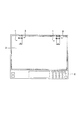
図1及び図2は本発明に係る事務機器の一例を示す図である。図3は機器本体に対する原稿圧着板の平行位置の関係を示す図である。なお、図3において、本発明に係る原稿圧着板開閉装置の位置関係が分かるように原稿圧着板開閉装置を実線で示した。図4〜図8は本発明に係る原稿圧着板開閉装置の一例を示す図である。本発明に係る原稿圧着板開閉装置は、図1〜図8に示すように、事務機器の機器本体2の後端部に取り付けられ、原稿圧着板3を開閉可能に支持するものである。事務機器としては、特に限定されず、例えば、複写機、印刷機、ファクシミリ、スキャナー等が挙げられ、複写機が好ましく、特にファクシミリ付複写機が好ましいものとして挙げられる。
1 and 2 are diagrams showing an example of office equipment according to the present invention. FIG. 3 is a diagram showing the relationship of the parallel position of the original cover on the device body. In FIG. 3, the original pressure plate opening / closing device is shown by a solid line so that the positional relationship of the original pressure plate opening / closing device according to the present invention can be understood. 4 to 8 are views showing an example of a document crimping plate opening / closing device according to the present invention. As shown in FIGS. 1 to 8, the document crimping plate opening / closing device according to the present invention is attached to the rear end portion of the apparatus
原稿圧着板3の上部には、原稿自動送り装置31が設けられている。原稿自動送り装置31は、複数枚の原稿を効率よく複写したり印刷したり送信したりするためのものである。この原稿自動送り装置31は、原稿圧着板3の上部の一側に設けた原稿送り部32を備え、この原稿送り部32へ原稿をセットすると、自動的に機器本体2の原稿読取部23(原稿読取部がコンタクトガラス20である場合もある。)へ複数枚の原稿が順次送られて複写や印刷、或いは送信が行えるように構成されている。
An
本発明に係る原稿圧着板開閉装置1は、事務機器の機器本体2に対して原稿圧着板3を開閉可能に支持する原稿圧着板開閉装置であって、当該原稿圧着板開閉装置1の装置本体4を、前記機器本体2に移動可能に取り付けられ、両側板を有する取付部材6と、この取付部材6の両側板62に回動可能に軸支され、前記原稿圧着板3が取り付けられる支持部材7とを備えたものとすると共に、前記機器本体2に対する前記原稿圧着板3の平行位置を調節する位置調節手段5を設け、この位置調節手段5を、前記機器本体2に取り付けられる調節板52と、前記取付部材6の両側板62に支持され、前記調節板52と係合手段54を介して係合して前記機器本体2に対する前記取付部材6の位置を前後方向のいずれか一方に可変させる作動部材53と、前記取付部材6の両側板62に取り付けられ前記作動部材53を動作させる螺合部材55と、で構成し、前記螺合部材55の一部を前記取付部材6の両側板62の一方に露出させることにより、前記取付部材6の前後方向の位置を前記装置本体4の側部側から調節できるように構成したことに特徴がある。原稿圧着板3を開閉可能に支持する開閉装置は、機器本体2の後端部に2つ取り付けられており、2つの開閉装置のうち一方が本発明に係る原稿圧着板開閉装置1であればよい。すなわち、2つの開閉装置のうち一方が本発明に係る原稿圧着板開閉装置1であってもよいし、両方とも本発明に係る原稿圧着板開閉装置1であってもよく、図示例は両方が本発明に係る原稿圧着板開閉装置1である場合である。
The document crimping plate opening /
装置本体4は、機器本体2に移動可能に取り付けられ、両側板62、62を有する取付部材6と、この取付部材6の両側板62、62に回動可能に軸支され、原稿圧着板3が取り付けられる支持部材7とを備え、さらに支持部材7と原稿圧着板3との間に、支持部材7に重なり合うと共に支持部材7の自由端部に回動可能に軸支され、かつ、原稿圧着板3に取り付けられるリフト部材8が設けられ、取付部材6と支持部材7との間に、原稿圧着板3を開成方向に回動付勢すると共に、リフト部材8を支持部材7と重なり合う方向へ付勢する弾性手段(図示せず)が設けられていることが好ましい。
The apparatus main body 4 is movably attached to the apparatus
取付部材6は、機器本体2に移動可能に取り付けられる底板61と、底板61の両側端部からそれぞれ底板61に対して直交する方向(略直交する方向も含む。)に延びる両側板62、62と、底板61の一端部(後端部)から底板61に対して直交する方向(略直交する方向も含む。)に延びる略矩形状の後板63と、からなる。
The
底板61は、略矩形状に形成されている。この底板61には、例えばネジやボルト等の2つの締結部材25、26によって取付部材6を機器本体2に移動可能に取り付けるための取付孔65が設けられている。2つの締結部材は、機器本体2の前方側の第1取付孔21に螺合される第1締結部材25と、機器本体2の後方側の第2取付孔22に螺合される第2締結部材26とからなる。第1締結部材25は、第1取付孔21に螺合される螺合部25aと、螺合部25aより径が大きな寸法で形成されている頭部25bとからなる。第2締結部材26は、第2取付孔22に螺合される螺合部26aと、螺合部26aより径が大きな寸法で形成されている頭部26bと、螺合部26aと頭部26bとの間に設けられるスライド部26cとからなる。第2締結部材26のスライド部26cは、螺合部26aより径が大きく頭部26bより径が小さく、かつ、底板61の厚さより軸方向の長さが長い円柱状に形成されている。
The
取付孔65は、底板61の幅方向の中央部にその長手方向に延びる略長円状に形成されている。この取付孔65の中央部は、第1締結部材25の頭部25b及び第2締結部材26の頭部26bより径が大きな寸法の円形状に形成されている。取付孔65の前方側の前方部65aが第1取付孔21と孔合わせする箇所である。この前方部65aの幅は、第1締結部材25の螺合部25aより径が大きくその頭部25bより径が小さな寸法で形成されている。取付孔65の後方側の後方部65bが第2取付孔22と孔合わせする箇所である。この後方部65bの幅は、第2締結部材26のスライド部26cより若干大きな寸法で形成されている。これにより、取付孔65の前方部65aが第1取付孔21と、後方部65bが第2取付孔22とそれぞれ孔合わせした状態でその第1取付孔21に第1締結部材25の螺合部25aを螺合させると共に、その第2取付孔22に第2締結部材26の螺合部26aを螺合させてスライド部26cの端部を機器本体2の上面に当接又は近接させることで、機器本体2の前後方向にスライド可能に取付部材6すなわち装置本体4が機器本体2に取り付けられることになる。
The
取付部材6の側板62は、略L字状に形成され、底板61に対して直交する方向(略直交する方向も含む。)に延び、この先端部(上部)に、第1ヒンジピン11が挿通されるシャフト孔(図示せず)が設けられている。側板62のシャフト孔より底板61側(下方)で、かつ、内側(前方)に偏した位置には、受圧ピン13が挿通される受圧ピン孔(図示せず)が設けられている。受圧ピン13は、カムスライダー92の底部の外表面が当接する受圧部材であり、この受圧部材は、受圧ピン13等のピンに限定されず、ローラ例えば受圧ローラでもよい。
The
支持部材7は、天板である上板71と、上板71の両側端部からそれぞれ上板71に対して直交する方向(略直交する方向も含む。)に延びる両側板72、72と、側板72、72の先端部を互いに対向する側に90°折り曲げてなる拘持板73と、からなる。これらの上板71、両側板72、72、拘持板73で収容部78が構成されている。
The
両側板72、72の一端部(後端部)には、第2ヒンジピン12が挿通される第2ヒンジピン孔(図示せず)が設けられていると共に、作動ピン14が入り込む切欠部74が設けられている。両側板72、72の他端部(前端部)には、シャフト挿通孔(図示せず)が設けられている。両側板72、72のシャフト挿通孔と取付部材6のシャフト孔とが孔合わせされてこれら各孔に第1ヒンジピン11が挿通されることによって、支持部材7が取付部材6に第1ヒンジピン11を軸に回動可能に連結されている。
A second hinge pin hole (not shown) through which the
リフト部材8は、厚さが厚い原稿も機器本体2の上面に安定して圧着させるためのものである。リフト部材8は、原稿圧着板3の後端側にビス等で取り付けられる上板81と、この上板81の両端部からそれぞれ上板81に対して直交する方向(略直交する方向も含む。)に延びる両側板82とから略コ字状であって支持部材7を覆うように形成されている。リフト部材8の一端部(後端部)の中央より上板81側の箇所には第2ヒンジピン挿通孔(図示せず)が設けられていると共に、第2ヒンジピン挿通孔より他端部側で、かつ、中央より上板81側とは反対側の箇所には作動ピン14が挿通される作動ピン孔(図示せず)が設けられている。両側板82、82の作動ピン孔に作動ピン14が挿通されて固定されている。リフト部材8の両側板82、82の第2ヒンジピン挿通孔と支持部材7の両側板72、72の第2ヒンジピン孔とが孔合わせされてこれら各孔に第2ヒンジピン12が挿通されることによって、リフト部材8と支持部材7とが第2ヒンジピン12を軸に互いに回動可能に連結されている。
The
弾性手段は、原稿圧着板3を開成方向に回動付勢すると共に、リフト部材8を支持部材7と重なり合う方向へ付勢し、かつ、原稿圧着板3が所定の開成角度以下のとき、原稿圧着板3を付勢する弾力が原稿圧着板3のモーメントより小さいものである。なお、本発明において開成方向とは、原稿圧着板3を回動させる際に原稿圧着板3がコンタクトガラス20から離間する方向をいう。本発明における開成角度とは、機器本体2の上面であるコンタクトガラス20面に対する原稿圧着板3の角度である。本発明における所定の開成角度とは、例えば、弾性手段による原稿圧着板3を付勢する付勢力が原稿圧着板3のモーメントより小さくなる角度である。
The elastic means urges the
弾性手段は、例えば、圧縮コイルスプリング(図示せず)である。圧縮コイルスプリングは、支持部材7内に挿入されて作動ピン14と受圧ピン13との間に弾設されている。圧縮コイルスプリングの作動ピン14との間には、バネ受け部材91が設けられていると共に、圧縮コイルスプリングの受圧ピン13との間には、カムスライダー92が設けられている。
The elastic means is, for example, a compression coil spring (not shown). The compression coil spring is inserted into the
圧縮コイルスプリングは、その個数は特に限定されず、1個でも2個以上でもよく、バネ受け部材91及びカムスライダー92をそれぞれ互いに離間する方向に付勢するものである。圧縮コイルスプリングは、原稿圧着板3を開成方向に回動付勢すると共に、原稿圧着板3が所定の開成角度(例えば、20°(20°前後も含む。))以下のとき、原稿圧着板3を付勢する弾力が原稿圧着板3のモーメントより小さくなるものである。
The number of compression coil springs is not particularly limited, and may be one or more, and biases the
バネ受け部材91及びカムスライダー92は、断面矩形の有底筒体状に形成されている。これらのバネ受け部材91及びカムスライダー92は、互いの開口部が向き合うと共にこれらの間に圧縮コイルスプリングが収容された状態で支持部材7の収容部78にそれぞれ個別に摺動可能に嵌合された状態で挿入されている。バネ受け部材91及びカムスライダー92は、取付部材6の底板61と支持部材7(上板71)が略平行になっているとき(例えば機器本体2の上面のコンタクトガラス20上に原稿圧着板3を密着させたとき(原稿圧着板が閉成位置にあるとき))、支持部材7の収容部78内に嵌合される長さで形成されている。
The
カムスライダー92の底部(閉塞部ということがある。)の外表面の略中央部には、突部92aが設けられている。この突部92aは、支持部材7の上板71に略平行に延びて形成されている。突部92aより拘持板73側のカムスライダー92の底部外表面は漸次傾斜された傾斜部92bとして形成されている。このカムスライダー92の底部の外表面の突部92a及び傾斜部92bが1種のカムとして形成されている。
A
すなわち、原稿圧着板3をコンタクトガラス20から離間する方向(上方)に第1ヒンジピン11を軸に回動させると、受圧ピン13に当接する箇所が突部92aから傾斜部92bへと徐々に摺動すると共に、カムスライダー92が圧縮コイルスプリングによって支持部材7内を後端部側へと押圧されて摺動し、圧縮コイルスプリングが徐々に伸びる。そして、原稿圧着板3が最大使用開放角度(例えば、60°(60°前後を含む。)〜70°(70°前後を含む。))になると、その開閉が原稿圧着板開閉規制機構(図示せず)によって規制される。
That is, when the
圧縮コイルスプリング内には、ダンパー装置(図示せず)が設けられている場合がある。このダンパー装置は、原稿圧着板3が閉成方向に回動したとき、原稿圧着板3の所定の回動角度である開成角度以下の特定の角度以下(例えば10°前後以下)においてのみその原稿圧着板3の回動速度を低減させるように動作するものである。なお、本発明において閉成方向とは、原稿圧着板3を回動させる際に原稿圧着板3がコンタクトガラス20に近づく方向をいう。本発明における特定の角度以下とは、前記の所定の開成角度以下の角度であれば特に限定されない。
A damper device (not shown) may be provided in the compression coil spring. When the
ダンパー装置は、例えば、オイルダンパ装置等である。ダンパー装置は、原稿圧着板3の特定の角度以下(例えば10°前後以下)においてのみその原稿圧着板3の回動速度を低減させることができれば、特に限定されない。ダンパー装置は、例えば、シリコンオイル等のオイルが充填されているシリンダと、シリンダ内に移動可能に設けられ、ピストンロッドが連結されていると共に、ピストンロッドのシリンダから露出している露出長が長くなるように付勢されるピストン(図示せず)とから主に構成されている。
The damper device is, for example, an oil damper device. The damper device is not particularly limited as long as the rotation speed of the
位置調節手段5は、取付部材6を介して機器本体2に対する装置本体4の平行位置、すなわち、原稿圧着板3の平行位置を調節するものである。この位置調節手段5は、例えば、機器本体2に取り付けられる調節板52と、取付部材6の両側板62、62に支持され、係合手段54を介して調節板52と係合して機器本体2に対する取付部材6の位置を可変させる作動部材53と、取付部材6の両側板62、62の一方に設けられ、作動部材53を動作させる操作部51とを備えている。
The position adjusting means 5 adjusts the parallel position of the apparatus main body 4 with respect to the apparatus
調節板52は、図7〜図9に示すように、取付部材6の底板61より若干小さな略矩形板状に形成されている。調節板52の幅は、取付部材6の側板62、62間の長さより若干短い寸法で形成されている。この調節板52は、底板61上に重ね合わされるように取り付けられている。調節板52の一方の端部(前方側となる端部)近傍には、第1締結部材25の螺合部25aが挿入される挿入孔52aが設けられ、この挿入孔52aを第1取付孔21及び取付孔65の前方部65aと孔合わせして、第1締結部材25の螺合部25aを挿入孔52a及び前方部65aを貫通させてから第1取付孔21に螺合させることによって、調節板52が機器本体2に取り付けられている。また、調節板52には、取付孔65の中央部及び後方部65bを露出させる長円状の貫通孔52bが設けられており、取付部材6すなわち装置本体4の機器本体2の前後方向へのスライドが可能になっている。
As shown in FIGS. 7 to 9, the
作動部材53は、図7、図8及び図10に示すように、係合手段54を介して調節板52と係合して機器本体2に対する取付部材6の位置を可変できればどのように形成してもよく、例えば、矩形筒体状に形成されている。すなわち、作動部材53の外形は、矩形状に形成されていると共に、内形が円形であって内面にネジ溝53aが螺設されている。作動部材53の長さ(軸方向の長さ)は、取付部材6の側板62、62間の長さより短い寸法で形成されている。この作動部材53のネジ溝53aに螺合部材55が螺合されている。
As shown in FIGS. 7, 8 and 10, the
螺合部材55は、作動部材53のネジ溝53aに螺合して作動部材53を移動させるものであり、作動部材53を移動できれば、特に限定されず、例えば、ネジ56等が用いられる。このネジ56は、取付部材6の両側板62、62を貫通して設けられている。すなわち、側板62、62には、ネジ56が挿入されるネジ挿入孔(図示せず)がそれぞれ互いに対向して設けられている。ネジ挿入孔は、ネジ56の螺合部56aより径が大きく、その頭部56bより径が小さな例えば円形状に形成されている。ネジ挿入孔の位置は、取付孔65より後方側であって側板62、62間の作動部材53にネジ56が螺合されたとき、その作動部材53の一面(下面ということがある。)が底板61と低摩擦力で接触又は近接するような箇所であることが好ましい。
The screwing
ネジ56の螺合部56aの長さは、両側板62、62間の長さより長い寸法で両側板62、62のネジ挿入孔を貫通させたとき、先端部が側板62から突出し、この突出した先端部に例えばナット57を2つ螺合させ得る寸法で形成されていることが好ましい。これにより、ネジ56は、側板62、62に回転可能に取り付けられることになる。すなわち、ネジ56の螺合部56aを両側板62、62のネジ挿入孔に挿入してそれぞれ貫通させて、側板62から突出した螺合部56aに1つ目のナット57をネジ56が回転し得るように螺合させる。例えば、ネジ56の頭部56bを一方の側板62の外表面に接触又は近接させた状態で、他方の側板62の外表面から突出した螺合部56aに1つ目のナット57をナット57が他方の側板62の外表面に近接するように螺合させる。螺合後、2つ目のナット57を螺合部56aに螺合させて1つ目のナット57に接触させる。これにより、ネジ56は、側板62、62に回転可能で、かつ、ダブルナットで緩むことなく取り付けられることになる。このネジ56の頭部56bが操作部51であり、この操作部51を、例えば、ドライバー等の工具を用いて回転させる(操作する)ことによって、作動部材53が側板62、62間を往復移動するようになっている。
The length of the threaded
係合手段54は、調節板52と作動部材53を係合させて機器本体2に対する取付部材6すなわち装置本体4の位置を可変させるものであり、取付部材6の位置を可変できればどのように形成してもよく、例えば、調節板52及び作動部材53の一方に係合凸部58を設け、調節板52及び作動部材53の他方に係合凸部58と係合する係合凹部59を設けるようにしてもよい。
The engaging means 54 engages the adjusting
係合凸部58は、例えば、作動部材53の下面に設けられている。この係合凸部58は、どのように形成してもよく、例えば、作動部材53の下面から突出すると共に、作動部材53の長手方向に対して45°(45°前後を含む。)傾斜して下面の幅全体に延びている直線状に形成してもよいし、また、例えば、図11に示すように、円柱状の丸ボス等の凸部68を2つ以上例えば2つ下面から突出させると共に、これら2つの凸部68、68を作動部材53の長手方向に対して45°(45°前後を含む。)傾斜した直線上に配置して形成してもよい。
For example, the engaging
係合凹部59は、例えば、図7〜図9に示すように、調節板52に設けられている。この係合凹部59は、例えば、調節板52の取付孔65より後方側に係合凸部58と対向するように、すなわち調節板52の長手方向に対して45°(45°前後を含む。)傾斜して調節板52の両側部近傍までの間に設けられている。この係合凹部59の幅が係合凸部58の幅より若干大きな寸法で形成されている。この係合凹部59に係合凸部58が係合することによって、操作部51を操作すると、作動部材53が側板62、62間を移動して係合凸部58が係合凹部59に案内されながら、取付部材6すなわち装置本体4が機器本体2に対して前後方向のいずれか一方にスライド移動するようになっている。
For example, as shown in FIGS. 7 to 9, the
次に、本発明に係る原稿圧着板開閉装置の作用を説明する。 Next, the operation of the document crimping plate opening / closing device according to the present invention will be described.
原稿圧着板3は、機器本体2が使用されていない状態では、図2及び図4に示すように、機器本体2のコンタクトガラス20に密着されている。コンタクトガラス20上に原稿を載置するには、まず、原稿圧着板3のリフト部材8が取り付けられている箇所とは反対側の端部又はその近傍等に設けられている把持部を持って、図1に示すように、原稿圧着板3を上方に持ち上げる。すなわち、原稿圧着板3を第1ヒンジピン11を軸にのみ回動させてコンタクトガラス20面を外部に露出させる。このように原稿圧着板3を回動させるとき、原稿圧着板3は、圧縮コイルスプリングの弾力によって開成方向に回動付勢されているので、重量を感じさせることなく開成方向に回動することができる。
The
露出したコンタクトガラス20面上に原稿を載置した後、持ち上げた原稿圧着板3を降ろす。すなわち、原稿圧着板3をコンタクトガラス20と接触する方向に第1ヒンジピン11を軸に回動する(下方に移動する)。このように原稿圧着板3を回動させる場合、最初は圧縮コイルスプリングの付勢力に抗するために多少の力が必要になるが、例えば、原稿圧着板3の開成角度が20°(20°前後を含む。)以下になると、原稿圧着板3の重量が圧縮コイルスプリングの付勢力より強くなるので、原稿圧着板3は落下するように回動する。原稿圧着板3の開成角度が特定の角度例えば10°(10°前後を含む。)になると、ダンパー装置のピストンロッドの先端がカムスライダー92の底部の内面に当接して、ピストンロッドがシリンダ内に移動してピストンロッドの露出長が短くなり、原稿圧着板3の回動速度が低減される。その結果、原稿圧着板3の回動速度がダンパー装置によって制御されるので、原稿圧着板3が勢いよくコンタクトガラス20に衝突することがない。
After placing the document on the exposed
また、原稿が本のように厚さが厚い場合、原稿圧着板3を回動させる(下方に移動させる)と、原稿の支持部材7側の端部又はその近傍に原稿圧着板3の支持部材7の近傍の一部が接触し、原稿の支持部材7側の端部とは反対側の端部と原稿圧着板3との間に空間が形成される。すなわち、把持部側の端部の原稿圧着板3は浮いた状態となる。その浮いている原稿圧着板3の例えば把持部側の端部近傍をコンタクトガラス20側に押圧すると、作動ピン14がバネ受け部材91をカムスライダー92側に押圧して圧縮コイルスプリングの付勢力に抗してバネ受け部材91がカムスライダー92側に移動すると共に、原稿圧着板3(リフト部材8)が第2ヒンジピン12を軸に回動する。すなわち、原稿の上部を覆うように原稿圧着板3が移動する。例えば、その原稿の上部が平坦面である場合には、この上部に原稿圧着板3が面接触する。よって、厚さが厚い原稿が安定してコンタクトガラス20の面上に密着することになる。
When the original is thick like a book, when the original
このように原稿圧着板3は、回動可能に支持されているので、原稿の厚さに関係なく原稿を安定してコンタクトガラス20面上に密着することができる。
As described above, since the
複数枚の原稿を例えば複写するには、図2及び図4に示すように、機器本体2のコンタクトガラス20に原稿圧着板3が密着されている状態のまま、原稿圧着板3の上部の原稿送り部32に複数枚の原稿をセットする。セット後、スタートボタンを押し込み操作することにより、複数枚の原稿が、自動的に順次原稿送り部32から原稿読取部23へと送られて1枚ずつ連続的に複写される。
To copy a plurality of originals, for example, as shown in FIGS. 2 and 4, the original on the upper part of the
原稿が原稿送り部32から原稿読取部23へと送られるとき、原稿読取部23に対して原稿が平行に送られないと、原稿の読み取りが曲がって行われ、正確な複写等ができない。この場合、例えば、本発明に係る原稿圧着板開閉装置1には、位置調節手段5が設けられているので、機器本体2に対する原稿圧着板3の位置を調節することができる。すなわち、例えば、原稿圧着板3が機器本体2のコンタクトガラス20に密着されている場合には、前述と同様に原稿圧着板3を上方に持ち上げて第1ヒンジピン11を軸に回動させ、2つの原稿圧着板開閉装置1の第1締結部材25の頭部25bをそれぞれ露出させる。
When the document is sent from the
そして、例えば、右側(原稿自動送り装置31が設けられている側とは反対側)の原稿圧着板開閉装置1の第1締結部材25を回転させて第1締結部材25による締付けを緩めて取付部材6を前後方向にスライド可能にする。この状態のまま、操作部51であるネジ56の頭部56bを、例えば、ドライバー等の工具を用いて回転させる(操作する)と、作動部材53が側板62、62間を移動して係合凸部58が係合凹部59に案内されながら、取付部材6すなわち原稿圧着板3が機器本体2に対して前後方向のいずれか一方にスライド移動し、図3に2点鎖線で示したように原稿圧着板3が移動する。
Then, for example, the
具体的には、例えば、図8(a)に示すように、作動部材53が側板62、62間の中央に位置されている場合、ネジ56を一方向に回転させると、図8(b)に示すように、作動部材53が一方の側板62に当接又は近接すると共に、取付部材6すなわち装置本体4が前方にスライド移動する。また、ネジ56を逆方向に回転させると、図8(c)に示すように、作動部材53が他方の側板62に当接又は近接すると共に、取付部材6すなわち装置本体4が後方にスライド移動する。このように、操作部51を操作することにより、取付部材6がスライド移動して機器本体2に対する原稿圧着板3の平行位置を微調節することができる。その結果、原稿が原稿送り部32から原稿読取部23へと平行に送られるように機器本体2に対する原稿圧着板3の平行位置を微調節することができる。
Specifically, for example, as shown in FIG. 8A, when the operating
この場合、操作部51が取付部材6の側板62に設けられているので、操作する人が機器本体2の後ろ側に行かなくても操作部51を操作することができ、原稿圧着板3の位置調整と位置決めを簡単に行うことができる。また、取付部材6の底板61上であって調節板52の前方側の端部が移動する箇所に目盛35を設けることにより、装置本体4の機器本体2に対する位置調節の調節量を視認でき、装置本体4の調節を一層簡単に行うことができる。また、操作部51が側板62に設けられているために、原稿を機器本体2の上面上に載置するときには、操作部51が邪魔になることがないので、コンパクト化を図れる。
In this case, since the
したがって、本発明に係る原稿圧着板開閉装置1は、位置調節手段5の螺合部材55の一部を前記取付部材6の両側板62の一方に露出させ、この螺合部材55の一部を操作部51としたので、操作する人が装置本体4の後ろ側に行かなくても操作部51を操作することができ、原稿圧着板3の位置調整と位置決めを簡単に行うことができると共に、原稿を機器本体2の上面上に載置するときには、操作部51が邪魔になるがなくコンパクト化を図れる。
Therefore, the document crimping plate opening /
なお、以上の本発明の形態ではダンパー装置を用いたものを示したが、このダンパー装置を用いない構成の原稿圧着板開閉装置にそのまま適用することができる。 In the above embodiment of the present invention, the damper device is used. However, the present invention can be applied as it is to a document pressure plate opening / closing device having no damper device.
また、前記のネジ56の頭部56bは、球面状に形成されると共に略十字状の溝が形成されて、ドライバー等の工具を用いて回転させる(操作する)ものであるが、これに限定されず、例えば、図12に示すように、頭部101を円柱状に形成すると共にその周面に多数の溝を設けて、すなわち、頭部101を飾りビスにして、指で直接頭部を回転できるようにしてもよい。また、螺合部材55は、側板62、62間の周囲が作動部材53と螺合するネジ溝が設けられているものであればよいと共に、ナットを用いることなく側板62、62に回転可能に取り付けるようにしてもよい。例えば、図12に示すように、頭部101が飾りビスに形成されている螺合部材55を側板62、62のネジ挿入孔に挿入して、頭部101とは反対側の側板62から突出している先端部102にE型の止め輪103を取り付けて、側板62、62に回転可能に螺合部材55を取り付けるようにしてもよい。
The
以上説明したように本発明に係る原稿圧着板開閉装置は、操作する人が装置本体の後ろ側に行かなくても操作部を操作することができ、原稿圧着板の位置調整と位置決めを簡単に行うことができると共に、原稿を機器本体のコンタクトガラス上面上に載置するときには、操作部が邪魔になることがなくコンパクト化を図れるので、特に複写機、印刷機、ファクシミリ、スキャナー等の事務機器の原稿圧着板開閉装置として好適に用いられるものである。 As described above, the manuscript crimping plate opening / closing device according to the present invention can operate the operation unit even if the operator does not go to the back side of the device body, and can easily adjust the position and positioning of the manuscript crimping plate. In addition, when placing a document on the upper surface of the contact glass of the device body, the operation unit does not get in the way and it can be made compact, so office equipment such as copiers, printers, facsimiles, scanners, etc. It is suitably used as a document pressure plate opening / closing device.
1 原稿圧着板開閉装置
2 機器本体
3 原稿圧着板
4 装置本体
5 位置調節手段
6 取付部材
7 支持部材
8 リフト部材
51 操作部
52 調節板
53 作動部材
54 係合手段
55 螺合部材
56 ネジ
57 ナット
58 係合凸部
59 係合凹部
DESCRIPTION OF
Claims (5)
当該原稿圧着板開閉装置の装置本体を、前記機器本体に移動可能に取り付けられ、両側板を有する取付部材と、この取付部材の両側板に回動可能に軸支され、前記原稿圧着板が取り付けられる支持部材とを備えたものとすると共に、前記機器本体に対する前記原稿圧着板の平行位置を調節する位置調節手段を設け、この位置調節手段を、前記機器本体に取り付けられる調節板と、前記取付部材の両側板に支持され、前記調節板と係合手段を介して係合して前記機器本体に対する前記取付部材の位置を前後方向のいずれか一方に可変させる作動部材と、前記取付部材の両側板に取り付けられ前記作動部材を動作させる螺合部材と、で構成し、前記螺合部材の一部を前記取付部材の両側板の一方に露出させることにより、前記取付部材の前後方向の位置を前記装置本体の側部側から調節できるように構成したことを特徴とする、原稿圧着板開閉置。 A document crimping plate opening and closing device that supports the document crimping plate to be openable and closable with respect to the device body of the office equipment
The apparatus main body of the original pressure plate opening / closing device is movably attached to the apparatus main body, and has an attachment member having both side plates, and pivotally supported on both side plates of the attachment member, and the original pressure plate is attached. And a position adjusting means for adjusting the parallel position of the original pressure plate with respect to the apparatus main body, the position adjusting means being provided with an adjustment plate attached to the apparatus main body, and the attachment An actuating member supported by both side plates of the member and engaged with the adjusting plate via an engaging means to change the position of the mounting member with respect to the device main body in one of the front and rear directions; and both sides of the mounting member A screwing member that is attached to a plate and operates the operating member, and by exposing a part of the screwing member to one of both side plates of the mounting member, the front-rear direction of the mounting member Wherein the position and configured to be adjusted from side portion of the apparatus main body, the original cover closer location.
Priority Applications (4)
| Application Number | Priority Date | Filing Date | Title |
|---|---|---|---|
| JP2005010760A JP4676769B2 (en) | 2005-01-18 | 2005-01-18 | Document crimping plate opening and closing device and office equipment |
| US11/328,368 US7724405B2 (en) | 2005-01-18 | 2005-12-29 | Original cover closer and office equipment |
| KR1020060000831A KR100754413B1 (en) | 2005-01-18 | 2006-01-04 | opening and closing device for manuscript pressing plate and office apparatus |
| CNB2006100021944A CN100464254C (en) | 2005-01-18 | 2006-01-18 | Original cover closer and office equipment |
Applications Claiming Priority (1)
| Application Number | Priority Date | Filing Date | Title |
|---|---|---|---|
| JP2005010760A JP4676769B2 (en) | 2005-01-18 | 2005-01-18 | Document crimping plate opening and closing device and office equipment |
Publications (3)
| Publication Number | Publication Date |
|---|---|
| JP2006201293A JP2006201293A (en) | 2006-08-03 |
| JP2006201293A5 JP2006201293A5 (en) | 2008-02-28 |
| JP4676769B2 true JP4676769B2 (en) | 2011-04-27 |
Family
ID=36683556
Family Applications (1)
| Application Number | Title | Priority Date | Filing Date |
|---|---|---|---|
| JP2005010760A Expired - Fee Related JP4676769B2 (en) | 2005-01-18 | 2005-01-18 | Document crimping plate opening and closing device and office equipment |
Country Status (4)
| Country | Link |
|---|---|
| US (1) | US7724405B2 (en) |
| JP (1) | JP4676769B2 (en) |
| KR (1) | KR100754413B1 (en) |
| CN (1) | CN100464254C (en) |
Families Citing this family (20)
| Publication number | Priority date | Publication date | Assignee | Title |
|---|---|---|---|---|
| JP4306686B2 (en) * | 2006-02-27 | 2009-08-05 | ブラザー工業株式会社 | Image reading device |
| JP4673766B2 (en) * | 2006-02-27 | 2011-04-20 | ブラザー工業株式会社 | Image reading device |
| JP4577295B2 (en) * | 2006-10-25 | 2010-11-10 | 村田機械株式会社 | Image reading device |
| TWI405028B (en) * | 2007-04-19 | 2013-08-11 | Kem Hongkong Ltd | The original press plate opening and closing device and the original platen with the office equipment |
| JP5382760B2 (en) * | 2007-11-02 | 2014-01-08 | 株式会社ナチュラレーザ・ワン | Document crimping plate opening and closing device and office equipment equipped with document crimping plate |
| US20090154974A1 (en) * | 2007-12-13 | 2009-06-18 | Simotec Inc. | Original cover closer with quickly adjustable energy absorption capability |
| CN101534618B (en) * | 2008-03-10 | 2014-05-28 | 下西技研工业株式会社 | Starting and stopping device |
| US8224228B2 (en) * | 2008-10-20 | 2012-07-17 | Simotec Inc. | Cover closer |
| JP4883122B2 (en) * | 2009-03-30 | 2012-02-22 | ブラザー工業株式会社 | Image processing device |
| JP2011017391A (en) * | 2009-07-09 | 2011-01-27 | Shimonishi Giken Kogyo Kk | Mechanism for adjusting mounting position of opening and closing device |
| JP5541592B2 (en) * | 2009-12-14 | 2014-07-09 | 下西技研工業株式会社 | Attaching and fixing structure of the open / close device for the original cover |
| JP5881137B2 (en) * | 2011-01-25 | 2016-03-09 | 株式会社ナチュラレーザ・ワン | Document crimping plate opening and closing device and office equipment provided with the same |
| JP5995046B2 (en) * | 2012-02-10 | 2016-09-21 | 株式会社ナチュラレーザ・ワン | Document crimping plate opening and closing device and OA equipment |
| CN103471636B (en) * | 2012-06-06 | 2016-01-27 | 维嘉数控科技(苏州)有限公司 | A kind of flat device of optical detection apparatus |
| CN103900627B (en) * | 2012-12-26 | 2016-12-28 | 维嘉数控科技(苏州)有限公司 | Workbench glass cover-plate device for opening |
| JP6210480B2 (en) * | 2013-01-18 | 2017-10-11 | 株式会社ナチュラレーザ・ワン | Document crimping plate opening and closing device |
| US9100521B2 (en) * | 2013-06-13 | 2015-08-04 | Canon Kabushiki Kaisha | Image reading apparatus and image forming apparatus |
| JP6484889B2 (en) * | 2015-03-30 | 2019-03-20 | 下西技研工業株式会社 | Hinge |
| JP6975439B2 (en) * | 2017-01-10 | 2021-12-01 | 株式会社ナチュラレーザ・ワン | Original crimping plate switchgear and office equipment |
| JP2019176338A (en) * | 2018-03-28 | 2019-10-10 | キヤノン株式会社 | Image reading apparatus and image forming apparatus |
Citations (5)
| Publication number | Priority date | Publication date | Assignee | Title |
|---|---|---|---|---|
| JPH03155659A (en) * | 1989-11-14 | 1991-07-03 | Matsushita Electron Corp | Semiconductor device |
| JPH071446U (en) * | 1993-05-28 | 1995-01-10 | 加藤電機株式会社 | Document pressure plate opening / closing device |
| JPH0831679A (en) * | 1994-07-14 | 1996-02-02 | Mitsubishi Electric Corp | Coil former |
| JPH1195339A (en) * | 1997-09-24 | 1999-04-09 | Kato Electrical Mach Co Ltd | Original cover opening/closing device |
| JP2003004027A (en) * | 2001-06-18 | 2003-01-08 | Nisca Corp | Hinge device and original reader with hinge device |
Family Cites Families (8)
| Publication number | Priority date | Publication date | Assignee | Title |
|---|---|---|---|---|
| JP3155659B2 (en) * | 1994-02-08 | 2001-04-16 | ニスカ株式会社 | Document processing apparatus and image forming apparatus having the same |
| JPH10197971A (en) * | 1997-01-10 | 1998-07-31 | Canon Inc | Image reader |
| KR200249563Y1 (en) | 1997-06-11 | 2001-12-17 | 엄인자 | Assembly of fenders with folding structure |
| JP3798921B2 (en) * | 1999-04-14 | 2006-07-19 | 加藤電機株式会社 | Opening / closing device for document crimping device |
| JP2001223962A (en) * | 2000-02-09 | 2001-08-17 | Alpine Electronics Inc | Rotary electronic equipment |
| TW534547U (en) * | 2001-02-23 | 2003-05-21 | Avision Inc | Adjustable document cover height for scanner |
| JP2003315939A (en) * | 2002-04-22 | 2003-11-06 | Sharp Corp | Original cover opening/closing mechanism for original reader |
| JP3971276B2 (en) * | 2002-09-05 | 2007-09-05 | 加藤電機株式会社 | Hinge device |
-
2005
- 2005-01-18 JP JP2005010760A patent/JP4676769B2/en not_active Expired - Fee Related
- 2005-12-29 US US11/328,368 patent/US7724405B2/en not_active Expired - Fee Related
-
2006
- 2006-01-04 KR KR1020060000831A patent/KR100754413B1/en not_active IP Right Cessation
- 2006-01-18 CN CNB2006100021944A patent/CN100464254C/en not_active Expired - Fee Related
Patent Citations (5)
| Publication number | Priority date | Publication date | Assignee | Title |
|---|---|---|---|---|
| JPH03155659A (en) * | 1989-11-14 | 1991-07-03 | Matsushita Electron Corp | Semiconductor device |
| JPH071446U (en) * | 1993-05-28 | 1995-01-10 | 加藤電機株式会社 | Document pressure plate opening / closing device |
| JPH0831679A (en) * | 1994-07-14 | 1996-02-02 | Mitsubishi Electric Corp | Coil former |
| JPH1195339A (en) * | 1997-09-24 | 1999-04-09 | Kato Electrical Mach Co Ltd | Original cover opening/closing device |
| JP2003004027A (en) * | 2001-06-18 | 2003-01-08 | Nisca Corp | Hinge device and original reader with hinge device |
Also Published As
| Publication number | Publication date |
|---|---|
| CN100464254C (en) | 2009-02-25 |
| KR20060083861A (en) | 2006-07-21 |
| CN1808295A (en) | 2006-07-26 |
| JP2006201293A (en) | 2006-08-03 |
| KR100754413B1 (en) | 2007-08-31 |
| US20060158702A1 (en) | 2006-07-20 |
| US7724405B2 (en) | 2010-05-25 |
Similar Documents
| Publication | Publication Date | Title |
|---|---|---|
| JP4676769B2 (en) | Document crimping plate opening and closing device and office equipment | |
| TWI476140B (en) | Feeding unit for normal paper document and thicker media and medium processing apparatus having the same | |
| TWI412876B (en) | Original press plate opening and closing device (four) and the original platen of the office equipment | |
| JP4898215B2 (en) | Document crimping plate opening and closing device and office equipment | |
| JP5312832B2 (en) | Hinge | |
| JP5486333B2 (en) | Hinge | |
| JP2008224821A (en) | Image forming apparatus | |
| JP2018205370A (en) | Hinge device and business equipment using the same | |
| JP2007251934A (en) | Image reading apparatus | |
| JP5807943B2 (en) | Document crimping plate opening and closing device and office equipment | |
| JP2011227370A5 (en) | ||
| JP2008257167A (en) | Original pressing plate opening/closing device and office equipment equipped with original pressing plate | |
| JP4794144B2 (en) | Document crimping plate opening and closing device | |
| CN104243748A (en) | Image reading apparatus and image forming apparatus | |
| JP4898216B2 (en) | Document crimping plate opening and closing device and office equipment | |
| JP2007286630A (en) | Original pressing plate opening/closing device | |
| JP4563309B2 (en) | Paper cassette | |
| US7594649B2 (en) | Paper grabbing assembly | |
| JP2011104823A (en) | Image recorder | |
| JP4074993B2 (en) | Image reading device | |
| JPS5842478A (en) | Paper pushing mechanism for printer | |
| JP2019011807A (en) | Hinge | |
| JP2706206B2 (en) | Paper cassette | |
| JP3955444B2 (en) | Paper feeding device and image forming apparatus | |
| JPH0812526B2 (en) | Roller pressure contact mechanism of image forming device |
Legal Events
| Date | Code | Title | Description |
|---|---|---|---|
| A521 | Request for written amendment filed |
Free format text: JAPANESE INTERMEDIATE CODE: A523 Effective date: 20080110 |
|
| A621 | Written request for application examination |
Free format text: JAPANESE INTERMEDIATE CODE: A621 Effective date: 20080110 |
|
| A977 | Report on retrieval |
Free format text: JAPANESE INTERMEDIATE CODE: A971007 Effective date: 20100917 |
|
| A131 | Notification of reasons for refusal |
Free format text: JAPANESE INTERMEDIATE CODE: A131 Effective date: 20100928 |
|
| A521 | Request for written amendment filed |
Free format text: JAPANESE INTERMEDIATE CODE: A523 Effective date: 20101126 |
|
| TRDD | Decision of grant or rejection written | ||
| A01 | Written decision to grant a patent or to grant a registration (utility model) |
Free format text: JAPANESE INTERMEDIATE CODE: A01 Effective date: 20110118 |
|
| A01 | Written decision to grant a patent or to grant a registration (utility model) |
Free format text: JAPANESE INTERMEDIATE CODE: A01 |
|
| A61 | First payment of annual fees (during grant procedure) |
Free format text: JAPANESE INTERMEDIATE CODE: A61 Effective date: 20110128 |
|
| FPAY | Renewal fee payment (event date is renewal date of database) |
Free format text: PAYMENT UNTIL: 20140204 Year of fee payment: 3 |
|
| R150 | Certificate of patent or registration of utility model |
Ref document number: 4676769 Country of ref document: JP Free format text: JAPANESE INTERMEDIATE CODE: R150 Free format text: JAPANESE INTERMEDIATE CODE: R150 |
|
| FPAY | Renewal fee payment (event date is renewal date of database) |
Free format text: PAYMENT UNTIL: 20140204 Year of fee payment: 3 |
|
| S111 | Request for change of ownership or part of ownership |
Free format text: JAPANESE INTERMEDIATE CODE: R313113 |
|
| FPAY | Renewal fee payment (event date is renewal date of database) |
Free format text: PAYMENT UNTIL: 20140204 Year of fee payment: 3 |
|
| R350 | Written notification of registration of transfer |
Free format text: JAPANESE INTERMEDIATE CODE: R350 |
|
| R250 | Receipt of annual fees |
Free format text: JAPANESE INTERMEDIATE CODE: R250 |
|
| R250 | Receipt of annual fees |
Free format text: JAPANESE INTERMEDIATE CODE: R250 |
|
| R250 | Receipt of annual fees |
Free format text: JAPANESE INTERMEDIATE CODE: R250 |
|
| R250 | Receipt of annual fees |
Free format text: JAPANESE INTERMEDIATE CODE: R250 |
|
| R250 | Receipt of annual fees |
Free format text: JAPANESE INTERMEDIATE CODE: R250 |
|
| LAPS | Cancellation because of no payment of annual fees |