JP6210480B2 - Document crimping plate opening and closing device - Google Patents
Document crimping plate opening and closing device Download PDFInfo
- Publication number
- JP6210480B2 JP6210480B2 JP2013007332A JP2013007332A JP6210480B2 JP 6210480 B2 JP6210480 B2 JP 6210480B2 JP 2013007332 A JP2013007332 A JP 2013007332A JP 2013007332 A JP2013007332 A JP 2013007332A JP 6210480 B2 JP6210480 B2 JP 6210480B2
- Authority
- JP
- Japan
- Prior art keywords
- slider
- cover
- side plates
- attached
- hinge pin
- Prior art date
- Legal status (The legal status is an assumption and is not a legal conclusion. Google has not performed a legal analysis and makes no representation as to the accuracy of the status listed.)
- Active
Links
Images


Classifications
-
- E—FIXED CONSTRUCTIONS
- E05—LOCKS; KEYS; WINDOW OR DOOR FITTINGS; SAFES
- E05F—DEVICES FOR MOVING WINGS INTO OPEN OR CLOSED POSITION; CHECKS FOR WINGS; WING FITTINGS NOT OTHERWISE PROVIDED FOR, CONCERNED WITH THE FUNCTIONING OF THE WING
- E05F1/00—Closers or openers for wings, not otherwise provided for in this subclass
- E05F1/08—Closers or openers for wings, not otherwise provided for in this subclass spring-actuated, e.g. for horizontally sliding wings
- E05F1/10—Closers or openers for wings, not otherwise provided for in this subclass spring-actuated, e.g. for horizontally sliding wings for swinging wings, e.g. counterbalance
- E05F1/12—Mechanisms in the shape of hinges or pivots, operated by springs
- E05F1/1246—Mechanisms in the shape of hinges or pivots, operated by springs with a coil spring perpendicular to the pivot axis
- E05F1/1253—Mechanisms in the shape of hinges or pivots, operated by springs with a coil spring perpendicular to the pivot axis with a compression spring
- E05F1/1261—Mechanisms in the shape of hinges or pivots, operated by springs with a coil spring perpendicular to the pivot axis with a compression spring for counterbalancing
-
- E—FIXED CONSTRUCTIONS
- E05—LOCKS; KEYS; WINDOW OR DOOR FITTINGS; SAFES
- E05D—HINGES OR SUSPENSION DEVICES FOR DOORS, WINDOWS OR WINGS
- E05D3/00—Hinges with pins
- E05D3/06—Hinges with pins with two or more pins
- E05D3/12—Hinges with pins with two or more pins with two parallel pins and one arm
-
- E—FIXED CONSTRUCTIONS
- E05—LOCKS; KEYS; WINDOW OR DOOR FITTINGS; SAFES
- E05Y—INDEXING SCHEME RELATING TO HINGES OR OTHER SUSPENSION DEVICES FOR DOORS, WINDOWS OR WINGS AND DEVICES FOR MOVING WINGS INTO OPEN OR CLOSED POSITION, CHECKS FOR WINGS AND WING FITTINGS NOT OTHERWISE PROVIDED FOR, CONCERNED WITH THE FUNCTIONING OF THE WING
- E05Y2201/00—Constructional elements; Accessories therefore
- E05Y2201/60—Suspension or transmission members; Accessories therefore
- E05Y2201/622—Suspension or transmission members elements
- E05Y2201/638—Cams; Ramps
-
- E—FIXED CONSTRUCTIONS
- E05—LOCKS; KEYS; WINDOW OR DOOR FITTINGS; SAFES
- E05Y—INDEXING SCHEME RELATING TO HINGES OR OTHER SUSPENSION DEVICES FOR DOORS, WINDOWS OR WINGS AND DEVICES FOR MOVING WINGS INTO OPEN OR CLOSED POSITION, CHECKS FOR WINGS AND WING FITTINGS NOT OTHERWISE PROVIDED FOR, CONCERNED WITH THE FUNCTIONING OF THE WING
- E05Y2800/00—Details, accessories and auxiliary operations not otherwise provided for
- E05Y2800/73—Single use of elements
-
- E—FIXED CONSTRUCTIONS
- E05—LOCKS; KEYS; WINDOW OR DOOR FITTINGS; SAFES
- E05Y—INDEXING SCHEME RELATING TO HINGES OR OTHER SUSPENSION DEVICES FOR DOORS, WINDOWS OR WINGS AND DEVICES FOR MOVING WINGS INTO OPEN OR CLOSED POSITION, CHECKS FOR WINGS AND WING FITTINGS NOT OTHERWISE PROVIDED FOR, CONCERNED WITH THE FUNCTIONING OF THE WING
- E05Y2900/00—Application of doors, windows, wings or fittings thereof
- E05Y2900/60—Application of doors, windows, wings or fittings thereof for other use
- E05Y2900/608—Application of doors, windows, wings or fittings thereof for other use for machines
Description
本発明は、複写機、印刷機、ファクシミリ、スキャナー等の事務機器に用いて好適な原稿圧着板開閉装置並びにこの原稿圧着板開閉装置を用いた事務機器に関するものである。 The present invention relates to a manuscript crimping plate opening / closing device suitable for office equipment such as a copying machine, a printing machine, a facsimile machine, and a scanner, and to an office device using the manuscript crimping plate opening / closing device.
複写機、印刷機、ファクシミリ、スキャナー等の事務機器の装置本体には、その装置本体に原稿圧着板が原稿圧着板開閉装置を介して開閉可能に取り付けられている。この原稿圧着板開閉装置は、一種のヒンジ機構であり、下記特許文献1に記載されているように、事務機器の装置本体へ取り付けられる底板とこの底板の両側より立設させた両側板を有する取付部材と、上板とこの上板の両側より垂設された両側板を有し、この両側板を前記取付部材の両側板へ第1ヒンジピンを介して回動可能に連結して成る支持部材と、原稿圧着板を取り付ける上板と、この上板の両側より垂設した両側板を有し、この両側板を前記支持部材の自由端側へ第2ヒンジピンを介して前記支持部材の回動方向とは逆方向へ回動可能に連結したリフト部材と、このリフト部材の両側板の間に取り付けられた作動部材と、この作動部材に当接して前記支持部材の前記両側板の間に摺動可能に収装された第1スライダーと、前記取付部材の前記両側板の間に設けられた受圧部材と、この受圧部材に接して前記支持部材の前記両側板の間に摺動可能に収装された第2スライダーと、前記第1スライダーと前記第2スライダーの間に弾設された圧縮コイルスプリングとで構成されている。
A document crimping plate is attached to an apparatus main body of an office machine such as a copying machine, a printing machine, a facsimile machine, and a scanner through a document crimping plate opening / closing device. This document crimping plate opening / closing device is a kind of hinge mechanism, and has a bottom plate attached to an apparatus main body of office equipment and both side plates erected from both sides of the bottom plate as described in
この従来公知の原稿圧着板を開くと、当該原稿圧着板を装置本体へ開閉可能に取り付けている原稿圧着板開閉装置の内部構造、とくに作動部材、第1スライダー、第2スライダー、受圧部材、圧縮コイルスプリングといった部分が外部へ露出することになって、操作者の目に入ることから、外観上好ましい印象を与えないことになる上に、作動部材、第1スライダー及び第2スライダーと支持部材との間の摺接面、さらには圧縮コイルスプリングの部分には、潤滑用のグリスやオイルが塗布されていることから、このグリスやオイルがコンタクトガラス上へ載置した原稿でコンタクトガラスよりはみ出した部分の端部を汚してしまったり、さらには、装置本体に対して原稿圧着板を取り付けたり、或は装置本体の修理の際に原稿圧着板を着脱するときなどに、原稿圧着板開閉装置に手を触れたり、つかんだりすることも多く、その際にグリスやオイルで手を汚してしまうといった問題もあった。 When this conventionally known document crimping plate is opened, the internal structure of the document crimping plate opening / closing device, which is attached to the apparatus main body so as to be opened and closed, particularly the operating member, the first slider, the second slider, the pressure receiving member, and the compression Since a part such as a coil spring is exposed to the outside and enters the eyes of the operator, it does not give a favorable impression in appearance, and the operating member, the first slider, the second slider, and the support member Since the grease and oil for lubrication are applied to the sliding contact surface between them and the portion of the compression coil spring, the grease and oil protruded from the contact glass on the original placed on the contact glass. The end of the part is soiled, and the original cover is attached to the main body of the device, or the original cover is attached or detached when the main body of the apparatus is repaired. Etc. Rutoki, or touch the original cover closer, it is also often the grasping, there is a problem such soiling their hands with grease or oil at that time.
本発明は上述した問題点を解決するためになされたものであり、その目的とするところは、原稿圧着板を開いた時に、内部構造が極力外部へ露出せず、かつ、コンタクトガラス上へ載置した原稿の端部がグリスで汚れたり、原稿圧着板を開閉したり、原稿圧着板を装置本体に対して着脱させる操作者や作業員の手がグリスやオイルなどで汚れないように工夫した、原稿圧着板開閉装置を提供せんとするにある。 The present invention has been made to solve the above-described problems. The object of the present invention is to prevent the internal structure from being exposed to the outside as much as possible when the original cover is opened, and to be mounted on the contact glass. The edge of the placed document is soiled with grease, the document crimping plate is opened and closed, and the operator's and worker's hands that attach and detach the document crimping plate to and from the main unit are designed not to be stained with grease or oil. The document pressure plate opening and closing device is to be provided.
前記目的を達成するために本発明の原稿圧着板開閉装置は、装置本体へ取り付けられる底板とこの底板の両側より立設させた両側板を有する取付部材と、上板とこの上板の両側より垂設された両側板とこの両側板より内側に折り曲げて設けた抱持片とを有し、前記両側板を前記取付部材の両側板へ第1ヒンジピンを介して回動可能に連結して成る支持部材と、上板とこの上板の両側部から垂設させた両側板を有し、前記支持部材の両側板の自由端側に第2ヒンジピンを介して回動可能に取り付けられたところの前記原稿圧着板を取り付けるリフト部材と、前記取付部材の両側板間に設けられた受圧部材と、この受圧部材に当接して前記支持部材内部に前記抱持片に抱えられて摺動可能に収装された第2スライダーと、前記リフト部材の両側板が前記第2ヒンジピンを介して回動する側に取り付けられた作動部材と、この作動部材に当接して前記支持部材内に前記抱持片に抱えられて摺動可能に収納された第1スライダーと、前記第2スライダーと前記第1スライダーの間に前記支持部材内に収装されて弾設された圧縮コイルスプリングから成り、前記作動部材、前記第1スライダー、及び前記第2スライダーが外側に露出している部分の少なくとも一部と
、前記圧縮コイルスプリングが外部へ露出している部分を覆うカバー部材を設け、このカバー部材の両側に設けた取付片の縁部を前記支持部材の上板の下面へ当接させて当該取付片を前記第2ヒンジピンへ取り付けたことを特徴とする。
In order to achieve the above-mentioned object, a document pressure plate opening / closing device of the present invention comprises a bottom plate attached to the apparatus body, a mounting member having both side plates erected from both sides of the bottom plate, an upper plate, and both sides of the upper plate. It has both side plates that are suspended and a holding piece that is bent inward from the both side plates, and the both side plates are rotatably connected to both side plates of the mounting member via a first hinge pin. A support member, an upper plate, and both side plates suspended from both side portions of the upper plate, which are pivotally attached to the free ends of the both side plates of the support member via second hinge pins. A lift member for attaching the original pressure plate, a pressure receiving member provided between both side plates of the attachment member, and abutting on the pressure receiving member and being held by the holding piece inside the support member so as to be slidable. Mounted second slider and both side plates of the lift member An actuating member attached to the side pivoted via the second hinge pin; a first slider abutting on the actuating member and held by the holding piece in the support member so as to be slidable; A compression coil spring which is housed and elastically placed in the support member between the second slider and the first slider, and the actuating member, the first slider, and the second slider are exposed to the outside. A cover member is provided to cover at least a part of the exposed portion and the portion where the compression coil spring is exposed to the outside, and the edge portions of the mounting pieces provided on both sides of the cover member are provided on the upper plate of the support member. The attachment piece is attached to the second hinge pin in contact with the lower surface .
さらに本発明は、前記カバー部材を、前記支持部材の上板或は両側板へ溶接、取付ビス、或はリベットピンで取り付けるように構成することができる。 Furthermore, the present invention can be configured such that the cover member is attached to the upper plate or both side plates of the support member by welding, mounting screws, or rivet pins.
本発明はさらに、前記カバー部材を、前記第1スライダーの上部側の一部と第2ヒンジピンの上部側を覆う第1カバー部と、この第1カバー部から絞られつつ約45度の角度で折り曲げられて設けられた第2カバー部と、この第2カバー部から第1カバー部に対して90度となる角度で折り曲げられた第3カバー部と、前記第1カバー部の両側部より折り曲げて形成させたところの前記第2ヒンジピンへ取り付けられる取付片と、で構成することができる。 The present invention further includes a first cover portion covering a part of the upper side of the first slider and an upper side of the second hinge pin, and an angle of about 45 degrees while being squeezed from the first cover portion. A second cover part provided by being bent, a third cover part bent at an angle of 90 degrees from the second cover part to the first cover part, and bent from both side parts of the first cover part And an attachment piece attached to the second hinge pin.
本発明はさらに、前記カバー部材を、前記第1スライダーの上部側を覆う第1カバー部と、この第1カバー部に対して略直角に折り曲げられたところの、前記支持部材の抱持片の間と第1スライダーと第2スライダーの間から外部へ露出している圧縮コイルスプリングを覆う第2カバー部と、前記第1カバー部の両側部から折り曲げ形成させたところの前記第2ヒンジピンへ取り付けられる取付片と、で構成することもできる。 The present invention further includes a first cover portion that covers the upper side of the first slider and a holding piece of the support member that is bent at a substantially right angle with respect to the first cover portion. And a second cover portion covering the compression coil spring exposed to the outside from between the first slider and the second slider, and attached to the second hinge pin bent from both sides of the first cover portion It can also be comprised with the attached piece.
上述したように本発明によれば、カバー部材によって、原稿圧着板開閉装置を構成する第2ヒンジピン、作動部材、第1スライダー、及び第2スライダーが外部へ露出する部分の一部と、圧縮コイルスプリングが外部へ露出する部分を覆うことができるので、これらの露出部分に付着している潤滑用或は防錆用のグリスやオイルによって、原稿圧着板の開閉操作を行う操作者や、或は組立、修理の際に原稿圧着板自体を装置本体へ取り付けたり、取り外しを行なったりする作業者の手を汚したり、装置本体のコンタクトガラス上に載置する原稿の端部がグリスやオイルで汚れてしまったりするのを有効に防止できるものである。 As described above, according to the present invention, the cover member includes the second hinge pin, the actuating member, the first slider, and a part of the portion where the second slider is exposed to the outside, and the compression coil. Since the spring can cover the exposed part, the operator who opens and closes the original pressure plate with the lubricating or anti-rust grease or oil adhering to the exposed part, or When assembling and repairing, the hand of the operator who attaches or removes the original pressure plate itself to the main body of the machine is soiled, or the edge of the original placed on the contact glass of the main body of the equipment is soiled with grease or oil. It is possible to effectively prevent such a situation.
また、原稿圧着板を開いた際に、外部へ露出する第2ヒンジピン、作動部材、第1スライダー、第2スライダーの一部、及び圧縮コイルスプリングが外部へ露出するのを防止できることから、美観を高め、原稿圧着板開閉装置のグレードアップを図ることができるものである。 Further, since the second hinge pin, the actuating member, the first slider, a part of the second slider, and the compression coil spring that are exposed to the outside can be prevented from being exposed to the outside when the original cover is opened, the aesthetic appearance is improved. It is possible to improve and upgrade the original pressure plate opening / closing device.
以下、本発明に係る原稿圧着板開閉装置を事務機器の一種である複写機に用いた場合について説明するが、本発明に係る原稿圧着板開閉装置は、複写機以外の、印刷機、ファクシミリ、スキャナー、或いは複合機と称せられる事務機器等にも広くにも用いることができるものである。 Hereinafter, a description will be given of a case where the original pressure plate opening / closing apparatus according to the present invention is used in a copying machine which is a kind of office equipment. The original pressure plate opening / closing apparatus according to the present invention is a printing machine, facsimile, It can also be widely used in office equipment or the like called a scanner or a multifunction machine.
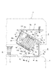
図1と図2は、本発明に係る原稿圧着板開閉装置3を用いた複写機Aを示す。その中で図1は本発明に係るカバー部材14と15を取り付けた状態を示し、図2はカバー部材14と15を取り付けてない状態を示している。この図2を見れば、原稿圧着板を開くと、後述する原稿圧着板開閉装置3の内部構造(作動部材9、第1スライダー10、第2スライダー12、及び圧縮コイルスプリング13或は13aなど)が外部へ露出していることが解る。左側の原稿圧着板開閉装置3aにおいても指示記号を付けてはいないが同様である。
FIG. 1 and FIG. 2 show a copying machine A using a document crimping plate opening /
図面によれば、事務機器の一種である複写機Aは、装置本体1と、この装置本体1の上面に設けたコンタクトガラス1a上を覆う原稿圧着板2とを備えており、本発明に係る原稿圧着板開閉装置3は、複写機Aの装置本体1に対し原稿圧着板2を開閉可能に取り付ける一種のヒンジ機構である。通常左右一対のものが用いられており、以下に右側の原稿圧着板開閉装置3について説明するが、左側の原稿圧着板開閉装置3aにも同じように実施できるものである。この左側の原稿圧着板開閉装置3aは、原稿圧着板2に取り付けられた原稿自動送り装置2aの側を支持するので、重量のあることから、後述する圧縮コイルスプリング13a、13aを2個並べて使用している。しかし、この左側のものも右側の原稿圧着板開閉装置3と同じ上記技術的課題を有していることから、この左側の原稿圧着板開閉装置3aにも本発明を実施することが必要である。
According to the drawings, a copying machine A, which is a kind of office equipment, includes an apparatus
図3〜図16は、図1と図2に示した原稿圧着板開閉装置3、3aのうち、右側の原稿圧着板開閉装置3のものを示している。左側の原稿圧着板開閉装置3aは、圧縮コイルスプリング13a、13aを2個使用している点を除いては、その構成は寸法が異なるのみで右側の原稿圧着板開閉装置3とその構造が同じである。
FIGS 16, of the original cover closer 3,3a shown in FIG. 1 and FIG. 2 shows that the right of the
図面に示したように、本発明に係る原稿圧着板開閉装置3は、複写機Aの装置本体1の後部上端へ取り付けられた取付部材4と、この取付部材4へ第1ヒンジピン5を介して回動可能に連結された支持部材6と、この支持部材6の自由端側へ第2ヒンジピン7を介して回動可能に連結されたところの原稿圧着板2を支持するリフト部材8と、このリフト部材8の第2ヒンジピン7側へ取り付けられた作動部材9と、この作動部材9に当接して前記支持部材6の両側板6b、6bの間に抱持片6c、6cに支えられて各摺動可能に収装された第1スライダー10と、前記取付部材4の両側板4b、4b間の前方に偏した位置に設けられた受圧部材11と、この受圧部材11に接して支持部材6の両側板6b、6bの間に抱持片6c、6cに抱えられて摺動可能に収装された第2スライダー12と、第1スライダー10と第2スライダー12の間にその一部を外部へ露出させて弾設された圧縮コイルスプリング13と、このとくに圧縮コイルスプリング13が外部へ露出する部分を覆う独立した部材のカバー部材14とで構成されている。
As shown in the drawings, the document pressing plate opening /
取付部材4は、装置本体1に取り付けられる底板4aと、この底板4aの両側端部からそれぞれ当該底板4aに対して直交する方向に折り曲げられた両側板4b、4bと、底板4aの一端部(とくに図7に示したように右端部)から当該底板4aに対して直交する方向(略直交する方向も含む)に延びる略矩形状の後板4cと、から構成されている。
The
取付部材4の底板4aは、略矩形状に形成され、取付釦部材4hと取付ネジ4j等で装置本体1へ取り付けるための取付孔4f、4gが設けられている。受圧部材11は、実施例のものは取付部材4の両側板4b、4b間に非回転に取り付けられているが、両側板4b、4b間に回転可能に取り付けられてもよい。さらに、受圧部材11はその形状についてとくに限定はないが、実施例のもののように断面円形状の軸体として、両側板4b、4b間に固定させ、その外周に回転可能に筒体を取り付けたものであってもよい。この受圧部材11は、後述するように、第2スライダー12のカム部12aと圧接しており、カム部12aと受圧部材11の外周には図示は省略するが潤滑用のグリスが塗布されている。
The
支持部材6は、上板6aと、この上板6aの両側端部からそれぞれ当該上板6aに対して直交する方向に折り曲げて垂設された両側板6b、6bと、両側板6b、6bの下端部側の一部を互いに対向する側に90°折り曲げて形成した抱持片6c、6cと、から構成され、両側板6b、6bの自由端側には後述する作動部材9のガイド溝6d、6dが設けられている。両側板6b、6bは取付部材4の両側板4b、4bの外側に位置し、この取付部材4の両側板4b、4bの後部側上端部へ、第1ヒンジピン5を介して両側板6b、6bを回転可能に連結させている。
The
リフト部材8は、原稿圧着板2の後端側をビス等で取り付ける上板8aと、この上板8aの両端部から下方へ折り曲げて垂設させた両側板8b、8bと、この両側板8b、8bの下端部側から外側へ折り曲げて形成させた取付板8c、8cから成る正面から見て略凸字状のものである。このリフト部材8は、支持部材6の両側板6b、6bの外側に位置して、その先端側に第2ヒンジピン7を介してその両側板8b、8bを支持部材6の両側板6b、6bへ当該支持部材6の取付部材4に対する回動方向とは逆方向へ回動するように連結されている。
The
リフト部材8の両側板8b、8bにはさらに、第2ヒンジピン7を支点とする旋回位置に作動部材9が取り付けられており、この作動部材9は、後述する第1スライダー10に圧接している。そして、作動部材9自身と第1スライダー10のカム部10aには図示してないが潤滑用のグリスが塗布されている。この作動部材9は、実施例では丸いピン状のものであり、リフト部材8の両側板8b、8b間に固定されているが、その形状に限定されない。さらにまた、それ自身が回転可能にリフト部材8の両側板8b、8bの間に取り付けられてもよく、上板8a、或は両側板8b、8bから折り曲げて形成させてもよい。
Further, an operating
支持部材6の両側板6b、6bの内側には、一対の第1スライダー10と第2スライダー12がその各スライド部10d、10d・12d、12dを抱持片6c、6cに抱えられて摺動可能に収装されている。この一対の第1スライダー10と第2スライダー12は、圧縮コイルスプリング13の各端部を収容させるスプリング収容部10c、12cが設けられた有底筒体状のもので、抱持片6c、6cの間から、湾曲部10b、12bが突出して設けられることにより、各スライダー全体の厚みを減少させることにより、材料の節約を図っている。
Inside the both
そして、この一対の第1スライダー10と第2スライダー12との間に圧縮コイルスプリング13が、その両端部をそれぞれのスプリング収容部10c、12cに収容させて弾設されており、その中間部は第1スライダー10と第2スライダー12、及び抱持片6c、6cとの間から外部へ露出しており、その表面には防錆用のオイル或はグリスが塗布されている。このように圧縮コイルスプリング13は、一対の第1スライダー10と第2スライダー12をそれぞれ互いに離間する方向に付勢することにより、それぞれの端部に設けたカム部10a、12aを作動部材9と受圧部材11に圧接させて、作動部材9を介してリフト部材8が支持部材6と重なり合うように付勢させ、同時に支持部材6とリフト部材8を原稿圧着板2の開成方向へ付勢させている。
A
第2スライダー12のカム部12aは、上昇傾斜部12eと、この上昇傾斜部12eに続いて設けられた下降傾斜部12fと、この下降傾斜部12fに続いて少し落ち込んだ位置に設けられた落ち込み平坦部12gから成り、その両側部には第1ヒンジピン5を内側両側部を逃がすための逃がし凹部12h、12hが設けられている。
The
第1スライダー10のカム部10aは、頂部側に隆起させた平坦部で構成されている。第2スライダー12の上昇傾斜部12eの始端部からは、さらに取付部材4側に受圧部材11の表面を覆うガード部材12jが突設して設けられている。
The
そして、カバー部材14は、主として圧縮コイルスプリング13の露出している部分を覆うもので合成樹脂製のものが原稿圧着板開閉装置3(或は原稿圧着板開閉装置3a)自体の美観を高め、グレードアップを図る意味で好ましい。しかし、合成樹脂製のものに限定されない。このカバー部材14は、第1スライダー10の上部側の一部と第2ヒンジピン7の上部側を覆う第1カバー部14aと、この第1カバー部14aから絞られつつ約45度の角度で折り曲げられて設けられた第2カバー部14bと、この第2カバー部14bから第1カバー部14aに対して90度となる角度で折り曲げられた第3カバー部14cと、で構成されており、この第3カバー部14cで支持部材6の抱持片6c、6cの間と第1スライダー10と第2スライダー12の間から外部へ露出している圧縮コイルスプリング13を覆っている。また、このカバー部材14は、第1カバー部14aの両側部から折り曲げた取付片14d、14dに設けた取付孔14f、14fへ第2ヒンジピン7を挿通させることにより当該第2ヒンジピン7へ取り付けられている。
The
即ち、このカバー部材14は、とくに図5に示したように、第2ヒンジピン7で支持部材6の両側板6b、6bとリフト部材8の両側板8b、8bを、それぞれ設けた挿通孔6e、6e・8d、8dへ挿通させて連結させる際に、第2ヒンジピン7へ取り付けられるもので、取り付けられると、とくに図7、9、10、11などに示したように、取付片14d、14dの縁部が支持部材6の上板6aの裏側へ当接することになる。このことにより、カバー部材14は、取付状態がグラグラすることなく安定した状態で、第2ヒンジピン7へ取り付けられている。
That is, as shown in FIG. 5, the
したがって、第3カバー部14cを支持部材6の抱持片6c、6cに固定する必要はなく、そのための固定手段である、取付ネジなどを用いなくとも良いので、第1スライダー10と第2スライダー12の円滑なスライドを阻害することはない。カバー部材14はこのように工夫されている。第3カバー部14cは、さらに、第1スライダー10と第2スライダー12の各湾曲部10b、12bと圧縮コイルスプリング13の外周を覆う湾曲覆部14gとこの湾曲覆部14gの両端側から延出されて抱持片6c、6cを覆う覆片14h、14hとを有している。
Therefore, it is not necessary to fix the
したがって、図6と図7に示したように、装置本体1の上面のコンタクトガラス1a面上に原稿圧着板2が閉じられて密着している状態において、カバー部材14は、その第1カバー部14aで第1スライダー10の頂部と作動部材9のいずれもグリスやオイルが付着している部分を覆うと共に、第2カバー部14bと第3カバー部14cで第1スライダー10と、圧縮コイルスプリング13と、第2スライダー12の一部のいずれも外部へ露出している部分を覆っている。
Therefore, as shown in FIGS. 6 and 7, the
したがって、コンタクトガラス1a上に載置させた原稿が薄いものであっても厚いものであっても、作動部材9や、第1スライダー10、第2スライダー12、及び圧縮コイルスプリング13などに付着しているグリスやオイルによって汚れてしまうことがないものである。また、ガード部材12jは原稿圧着板2の閉成時において、受圧部材11の回りの、とくにコンタクトガラス1a側を覆っている。
Therefore, regardless of whether the original placed on the
以上の閉成状態から原稿圧着板2の手前側を手に持って、装置本体1の上面から離間する方向(即ち開成方向)に第1ヒンジピン5を支点にして開くと、第2スライダー12の受圧部材11に当接する箇所が上昇傾斜部12eの下降方向へと徐々に摺動すると共に、第2スライダー12が圧縮コイルスプリング13によって受圧部材11の側へ支持部材6の中を摺動し、圧縮コイルスプリング13が徐々に伸び、図12と図13に示した最大開成角度(約90°)においては、落ち込み平坦部12gが第1ヒンジピン5に接して第2スライダーのストッパーとなり、さらに支持部材6の上板6aが取付部材4のストッパー部4d、4dに当接して、それ以上原稿圧着板2が開かないようになっている。
When the front side of the
図8〜図13に示したように、原稿圧着板2の全開閉角度範囲において、カバー部材14は、原稿圧着板開閉装置3の外部へ露出する、第2ヒンジピン7、作動部材9、第1スライダー10.圧縮コイルスプリング13、及び第2スライダー12の一部などの各表面側を覆うので、コンタクトガラス1a上へ原稿を載置する際に当該原稿が、第2ヒンジピン7、作動部材9、第1スライダー10.圧縮コイルスプリング13、及び第2スライダー12の一部などに当たって、グリスやオイルなどで汚されてしまう心配のないものである。また、原稿圧着板2の装置本体1への取り付け時や、装置本体1の修理、保守、点検時において装置本体1に対して原稿圧着板2の着脱を行う際には、原稿圧着板開閉装置3の部分を手で持って作業することがあるが、この際にも手にグリスやオイルが付着して汚してしまう虞のないものである。
As shown in FIGS. 8 to 13, the
また、本発明の原稿圧着板開閉装置3は、厚さに関係なく原稿を装置本体1のコンタクトガラス1a上に安定して載置させ、コンタクトガラス1aの上面を水平に覆うことができるものである。即ち、原稿が図10に示すように本のように厚い厚物原稿16の場合、原稿圧着板2を開き、厚物原稿16をコンタクトガラス1a上に載置させて原稿圧着板2を閉じると、厚物原稿16の端部が支持部材6の下面に当たるので、さらに、原稿圧着板2を閉じ方向へ押圧させてやると、リフト部材8が作動部材9を介して圧縮コイルスプリング13の弾力に抗して反転し、原稿圧着板2が厚物原稿16の上面を水平状態で覆うことができるものである。この際に、第2ヒンジピン7を支点に旋回する作動部材9は、支持部材6の両側板6b、6bに設けたガイド溝6d、6dの中へ嵌入して、リフト部材8の反転を可能にしている。また、以上のようにリフト部材8を介して原稿圧着板2が反転することで、厚物原稿16の複写面がコンタクトガラス1a上に平行に圧着することができると共に、外光がコンタクトガラス1aを介して装置本体内部へ侵入するのを防止して、不鮮明は複写とならないようにすることができるものである。
Further, the document pressing plate opening /
図17と図18は、カバー部材の他の実施例を示す。図面によれば、この実施例2に係るカバー部材20は、第1スライダー10の上部側を覆う第1カバー部20aと、この第1カバー部材20aに対して略直角に折り曲げられたところの、支持部材6の抱持片6c、6cの間と第1スライダー10と第2スライダー12の間から外部へ露出している圧縮コイルスプリング13を覆う第2カバー部20bから成り、第1カバー部20aの両側部から折り曲げたところの取付孔20d、20dを設けた取付片20c、20cを第2ヒンジピン7へ取り付けて構成されている。 その他の湾曲覆部20fや覆片20g、20gなどは実施例1のものと同じである。このカバー部材20は、取付片20c、20cの縁部を実施例1の図7、9、10、11、13に示したように、支持部材6の上板6aの下面へ当接させて第2ヒンジピン7へ取り付けられることにより、カバー部材20は、この取付片20c、20cによりグラグラすることなく、第2ヒンジピン7へ取り付けられている。
17 and 18 show another embodiment of the cover member. According to the drawing, the
この実施例2に係るカバー部材20は、実施例1のカバー部材14の第1カバー部14aのくびれた部分の幅を広くしたことから、より広く作動部材9と第1カムスライダー10等の外部露出部分を覆うことができることから、より一層グリスによる原稿の汚れを防止し、外観上の美観を高めることができるものである。
In the
尚、この実施例2に係る原稿圧着板開閉装置3の構成は、実施例1のものと同じであるので、その他の部材の説明を省略する。また、以上の実施例1或は2のものは、カバー部材14或は20を支持部材6へ固定するに当たり、当該カバー部材14、或は20を支持部材6の上板6a或は両側板6b、6bへ溶接、取付ビス、或はリベットピン等で固定する方法もある。
Since the configuration of the document pressing plate opening /
本発明に係るカバー部材は、例えば特開2008−224704号公報に記載されているように、公知構成の下記原稿圧着板開閉装置へも取り付けて用いることができる。即ち、底板とこの底板より垂設させたところの前記装置本体に設けた取付孔へ着脱可能に取り付けることのできる脚部と前記底板の両側部より立設させた両側板とを有する取付部材と、上板とこの上板の一端部側に設けた頂板と前記上板の両側部より垂設された両側板とこの両側板より内側に折り曲げて設けた抱持片とを有し、前記両側板を前記取付部材の両側板へヒンジピンを介して回動可能に連結して成る支持部材と、前記取付部材の両側板間に設けられた受圧部材と、この受圧部のカム部に当接して前記支持部材内部に摺動可能に収装されたスライダーと、このスライダーと前記頂板との間に前記支持部材内に収装されて弾設された圧縮コイルスプリングとから成る原稿圧着板開閉装置であって、カバー部材を前記スライダーが外側に露出している部分の少なくとも一部と、前記圧縮コイルスプリングが外部へ露出している部分を覆うように支持部材に固定して設けるものである。このように構成しても、本発明の目的を達成できるものである。 The cover member according to the present invention can be used by being attached to the following document crimping plate opening / closing device having a known configuration as described in, for example, Japanese Patent Application Laid-Open No. 2008-224704. That is, a mounting member having a bottom plate, legs that can be detachably attached to a mounting hole provided in the apparatus main body that is suspended from the bottom plate, and both side plates that are erected from both sides of the bottom plate; An upper plate, a top plate provided on one end side of the upper plate, both side plates suspended from both side portions of the upper plate, and a holding piece bent inward from the both side plates. A support member formed by rotatably connecting a plate to both side plates of the mounting member via a hinge pin, a pressure receiving member provided between the side plates of the mounting member, and a cam portion of the pressure receiving portion A document crimping plate opening / closing device comprising a slider slidably housed inside the support member, and a compression coil spring housed in the support member and elastically placed between the slider and the top plate. The cover member is on the outside At least part of the portion out, the compression coil spring is intended to provide fixed to the support member so as to cover the exposed portion to the outside. Even if comprised in this way, the objective of this invention can be achieved.
本発明は、原稿圧着板開閉装置を構成する、第1及び第2スライダーや作動部材、さらには受圧部材や圧縮コイルスプリングといった外部へ露出する部分を有し、グリスなどが付着している部分をカバー部材で覆うことができることから、コンタクトガラス上に載置させる原稿の端部が、グリスなどで汚れてしまうのを極めて有効に防止し、また、外観を損なうこれらの部材が外部へ露出することも防止することができることから、とくに複写機や複合機に代表される事務機器の原稿圧着板開閉装置に実施して好適である。 The present invention includes a first and second slider , an operating member, and a portion exposed to the outside, such as a pressure receiving member and a compression coil spring, which constitute the document pressing plate opening / closing device, and a portion to which grease or the like is attached. Since it can be covered with a cover member, the edge of the document placed on the contact glass is extremely effectively prevented from being stained with grease and the like, and those members that impair the appearance are exposed to the outside. Therefore, the present invention is particularly suitable for a document pressure plate opening / closing device of office equipment represented by a copying machine or a multifunction machine.
A 複写機
1 装置本体
2 原稿圧着板
3、3a 原稿圧着板開閉装置
4 取付部材
4a 底板
4b 両側板
4c 後板
4f 取付孔
4g 取付孔
5 第1ヒンジピン
6 支持部材
6a 上板
6b 両側板
6c 抱持片
6e 取付孔
7 第2ヒンジピン
8 リフト部材
8a 上板
8b 両側板
8d 取付孔
9 作動部材
10 第1スライダー
11 受圧部材
12 第2スライダー
13 圧縮コイルスプリング
13a 圧縮コイルスプリング
14 カバー部材
14a 第1カバー部
14b 第2カバー部
14c 第3カバー部
14d 取付片
14f 取付孔
15 カバー部材
20a 第1カバー部
20b 第2カバー部
20c 取付片
20d 取付孔
A Copying
Claims (4)
Priority Applications (5)
| Application Number | Priority Date | Filing Date | Title |
|---|---|---|---|
| JP2013007332A JP6210480B2 (en) | 2013-01-18 | 2013-01-18 | Document crimping plate opening and closing device |
| TW103101849A TWI529070B (en) | 2013-01-18 | 2014-01-17 | Opening-closing device of copy pressing plate and office machine using the same |
| CN201410022614.XA CN103945080B (en) | 2013-01-18 | 2014-01-17 | Opening-closing device of manuscript pressing plate and use its business machine |
| KR1020140006201A KR101569986B1 (en) | 2013-01-18 | 2014-01-17 | Original cover closer and office equipment having the same |
| US14/159,620 US8973218B2 (en) | 2013-01-18 | 2014-01-21 | Original cover closer and office equipment having the same |
Applications Claiming Priority (1)
| Application Number | Priority Date | Filing Date | Title |
|---|---|---|---|
| JP2013007332A JP6210480B2 (en) | 2013-01-18 | 2013-01-18 | Document crimping plate opening and closing device |
Publications (3)
| Publication Number | Publication Date |
|---|---|
| JP2014137543A JP2014137543A (en) | 2014-07-28 |
| JP2014137543A5 JP2014137543A5 (en) | 2016-03-10 |
| JP6210480B2 true JP6210480B2 (en) | 2017-10-11 |
Family
ID=51192551
Family Applications (1)
| Application Number | Title | Priority Date | Filing Date |
|---|---|---|---|
| JP2013007332A Active JP6210480B2 (en) | 2013-01-18 | 2013-01-18 | Document crimping plate opening and closing device |
Country Status (5)
| Country | Link |
|---|---|
| US (1) | US8973218B2 (en) |
| JP (1) | JP6210480B2 (en) |
| KR (1) | KR101569986B1 (en) |
| CN (1) | CN103945080B (en) |
| TW (1) | TWI529070B (en) |
Families Citing this family (12)
| Publication number | Priority date | Publication date | Assignee | Title |
|---|---|---|---|---|
| JP6440403B2 (en) * | 2014-08-11 | 2018-12-19 | キヤノン株式会社 | Image forming apparatus |
| JP6572471B2 (en) * | 2014-11-27 | 2019-09-11 | 下西技研工業株式会社 | Hinge |
| JP6436431B2 (en) * | 2015-06-18 | 2018-12-12 | 株式会社ナチュラレーザ・ワン | Video display device holding device and video display device using the holding device |
| JP6601905B2 (en) * | 2015-08-21 | 2019-11-06 | 株式会社ナチュラレーザ・ワン | Open / close support device and various devices using the open / close support device |
| JP6975439B2 (en) * | 2017-01-10 | 2021-12-01 | 株式会社ナチュラレーザ・ワン | Original crimping plate switchgear and office equipment |
| JP7090862B2 (en) * | 2017-05-30 | 2022-06-27 | 株式会社ナチュラレーザ・ワン | Hinge device and office equipment using this hinge device |
| JP6893688B2 (en) * | 2017-06-20 | 2021-06-23 | 株式会社ナチュラレーザ・ワン | Switchgear switchgear and various switchgear equipped with this switchgear switchgear |
| JP7133186B2 (en) * | 2017-12-13 | 2022-09-08 | 下西技研工業株式会社 | hinge |
| CN110313844A (en) * | 2019-08-21 | 2019-10-11 | 无锡市惠昌烧烤炉科技有限公司 | Oven damp hinge |
| CN110930801B (en) * | 2019-12-06 | 2021-07-02 | 宁波工程学院 | Project-based Internet of things system experiment box and experiment method |
| JP2022070476A (en) * | 2020-10-27 | 2022-05-13 | 株式会社ナチュラレーザ・ワン | Document crimp plate opening/closing device and office machine |
| JP2022085726A (en) * | 2020-11-27 | 2022-06-08 | 株式会社ナチュラレーザ・ワン | Hinge and office machine using this hinge |
Family Cites Families (15)
| Publication number | Priority date | Publication date | Assignee | Title |
|---|---|---|---|---|
| JPS63118036U (en) * | 1987-01-26 | 1988-07-30 | ||
| JP3641357B2 (en) | 1997-09-24 | 2005-04-20 | 加藤電機株式会社 | Document crimping plate opening and closing device |
| US5926917A (en) * | 1998-03-26 | 1999-07-27 | Dura Automotive Systems, Inc. | Door hinge assembly |
| US6353965B1 (en) * | 1999-08-23 | 2002-03-12 | Ching Lan Co., Ltd. | Guiding sheath assembly for a hinge of an eyeglass frame |
| KR100388989B1 (en) * | 2001-12-21 | 2003-06-25 | Samsung Electronics Co Ltd | Hinge device for opening/closing upper member of office machine |
| JP3971276B2 (en) * | 2002-09-05 | 2007-09-05 | 加藤電機株式会社 | Hinge device |
| JP4636826B2 (en) * | 2004-07-30 | 2011-02-23 | 下西技研工業株式会社 | Document crimping plate opening and closing device |
| JP4676769B2 (en) * | 2005-01-18 | 2011-04-27 | 加藤電機株式会社 | Document crimping plate opening and closing device and office equipment |
| JP4947570B2 (en) * | 2006-02-13 | 2012-06-06 | 下西技研工業株式会社 | Opening and closing device for original cover |
| JP5112718B2 (en) | 2007-03-08 | 2013-01-09 | 加藤電機株式会社 | Document crimping plate opening and closing device and office equipment equipped with document crimping plate |
| JP5223070B2 (en) * | 2007-05-24 | 2013-06-26 | 株式会社ナチュラレーザ・ワン | Document crimping plate opening and closing device |
| JP2011107485A (en) * | 2009-11-18 | 2011-06-02 | Katoh Electrical Machinery Co Ltd | Device for opening/closing original cover plate and business machine |
| JP5486333B2 (en) * | 2010-02-02 | 2014-05-07 | 下西技研工業株式会社 | Hinge |
| JP2012256029A (en) * | 2011-05-13 | 2012-12-27 | Tok Bearing Co Ltd | Hinge mechanism |
| TW201404996A (en) * | 2012-07-27 | 2014-02-01 | Hon Hai Prec Ind Co Ltd | Connection mechanism |
-
2013
- 2013-01-18 JP JP2013007332A patent/JP6210480B2/en active Active
-
2014
- 2014-01-17 KR KR1020140006201A patent/KR101569986B1/en not_active IP Right Cessation
- 2014-01-17 CN CN201410022614.XA patent/CN103945080B/en active Active
- 2014-01-17 TW TW103101849A patent/TWI529070B/en active
- 2014-01-21 US US14/159,620 patent/US8973218B2/en active Active
Also Published As
| Publication number | Publication date |
|---|---|
| KR101569986B1 (en) | 2015-11-17 |
| US8973218B2 (en) | 2015-03-10 |
| TW201429746A (en) | 2014-08-01 |
| CN103945080B (en) | 2017-06-13 |
| CN103945080A (en) | 2014-07-23 |
| US20140201946A1 (en) | 2014-07-24 |
| KR20140093640A (en) | 2014-07-28 |
| TWI529070B (en) | 2016-04-11 |
| JP2014137543A (en) | 2014-07-28 |
Similar Documents
| Publication | Publication Date | Title |
|---|---|---|
| JP6210480B2 (en) | Document crimping plate opening and closing device | |
| JP3899213B2 (en) | Document crimping plate opening and closing device | |
| JP2014137543A5 (en) | ||
| JP5966164B2 (en) | Document crimping plate opening and closing device and office equipment | |
| US20180347247A1 (en) | Hinge device and office equipment using the same | |
| JP2010282158A (en) | Device for opening and closing of original pressing plate | |
| JP2011107485A (en) | Device for opening/closing original cover plate and business machine | |
| JP2009058790A (en) | Original pressing plate opening/closing device and office equipment equipped with original pressing plate | |
| KR100896884B1 (en) | Hinge device and portable apparatus | |
| JP2013097363A5 (en) | ||
| JP5995046B2 (en) | Document crimping plate opening and closing device and OA equipment | |
| KR101285544B1 (en) | Device for comprising of apparatus for opening and closing and office machine with the device | |
| JP2008257167A (en) | Original pressing plate opening/closing device and office equipment equipped with original pressing plate | |
| KR101591159B1 (en) | Original cover closer and office equipment having the same | |
| JP5223070B2 (en) | Document crimping plate opening and closing device | |
| JP5811433B2 (en) | Document crimping plate opening and closing device and office equipment | |
| JP2013020191A5 (en) | ||
| JP2020106742A (en) | Document pressing plate opening/closing device and business machine with document pressing plate opening/closing device | |
| JP6810439B2 (en) | Open / close support device | |
| JP2019105775A (en) | Hinge | |
| JP2006023325A (en) | Original cover opening/closing device | |
| JP6870829B2 (en) | Switchgear and industrial equipment | |
| JP2023168078A (en) | Opening/closing support device | |
| JP2022190573A (en) | Hinge and office machine using the hinge | |
| JP2020201362A (en) | Manuscript crimp plate opening/closing device and business equipment having the same |
Legal Events
| Date | Code | Title | Description |
|---|---|---|---|
| A521 | Request for written amendment filed |
Free format text: JAPANESE INTERMEDIATE CODE: A523 Effective date: 20160113 |
|
| A621 | Written request for application examination |
Free format text: JAPANESE INTERMEDIATE CODE: A621 Effective date: 20160113 |
|
| A977 | Report on retrieval |
Free format text: JAPANESE INTERMEDIATE CODE: A971007 Effective date: 20161026 |
|
| A131 | Notification of reasons for refusal |
Free format text: JAPANESE INTERMEDIATE CODE: A131 Effective date: 20161108 |
|
| A521 | Request for written amendment filed |
Free format text: JAPANESE INTERMEDIATE CODE: A523 Effective date: 20170110 |
|
| A131 | Notification of reasons for refusal |
Free format text: JAPANESE INTERMEDIATE CODE: A131 Effective date: 20170411 |
|
| A521 | Request for written amendment filed |
Free format text: JAPANESE INTERMEDIATE CODE: A523 Effective date: 20170612 |
|
| TRDD | Decision of grant or rejection written | ||
| A01 | Written decision to grant a patent or to grant a registration (utility model) |
Free format text: JAPANESE INTERMEDIATE CODE: A01 Effective date: 20170808 |
|
| A61 | First payment of annual fees (during grant procedure) |
Free format text: JAPANESE INTERMEDIATE CODE: A61 Effective date: 20170905 |
|
| R150 | Certificate of patent or registration of utility model |
Ref document number: 6210480 Country of ref document: JP Free format text: JAPANESE INTERMEDIATE CODE: R150 |
|
| R250 | Receipt of annual fees |
Free format text: JAPANESE INTERMEDIATE CODE: R250 |
|
| R250 | Receipt of annual fees |
Free format text: JAPANESE INTERMEDIATE CODE: R250 |
|
| R250 | Receipt of annual fees |
Free format text: JAPANESE INTERMEDIATE CODE: R250 |
|
| R250 | Receipt of annual fees |
Free format text: JAPANESE INTERMEDIATE CODE: R250 |