JP5811433B2 - Document crimping plate opening and closing device and office equipment - Google Patents
Document crimping plate opening and closing device and office equipment Download PDFInfo
- Publication number
- JP5811433B2 JP5811433B2 JP2010160476A JP2010160476A JP5811433B2 JP 5811433 B2 JP5811433 B2 JP 5811433B2 JP 2010160476 A JP2010160476 A JP 2010160476A JP 2010160476 A JP2010160476 A JP 2010160476A JP 5811433 B2 JP5811433 B2 JP 5811433B2
- Authority
- JP
- Japan
- Prior art keywords
- document
- crimping plate
- arm member
- opening
- closing device
- Prior art date
- Legal status (The legal status is an assumption and is not a legal conclusion. Google has not performed a legal analysis and makes no representation as to the accuracy of the status listed.)
- Expired - Fee Related
Links
Images


Classifications
-
- G—PHYSICS
- G03—PHOTOGRAPHY; CINEMATOGRAPHY; ANALOGOUS TECHNIQUES USING WAVES OTHER THAN OPTICAL WAVES; ELECTROGRAPHY; HOLOGRAPHY
- G03B—APPARATUS OR ARRANGEMENTS FOR TAKING PHOTOGRAPHS OR FOR PROJECTING OR VIEWING THEM; APPARATUS OR ARRANGEMENTS EMPLOYING ANALOGOUS TECHNIQUES USING WAVES OTHER THAN OPTICAL WAVES; ACCESSORIES THEREFOR
- G03B27/00—Photographic printing apparatus
- G03B27/32—Projection printing apparatus, e.g. enlarger, copying camera
- G03B27/52—Details
- G03B27/62—Holders for the original
- G03B27/6207—Holders for the original in copying cameras
- G03B27/6221—Transparent copy platens
- G03B27/6228—Platen covers
-
- E—FIXED CONSTRUCTIONS
- E05—LOCKS; KEYS; WINDOW OR DOOR FITTINGS; SAFES
- E05F—DEVICES FOR MOVING WINGS INTO OPEN OR CLOSED POSITION; CHECKS FOR WINGS; WING FITTINGS NOT OTHERWISE PROVIDED FOR, CONCERNED WITH THE FUNCTIONING OF THE WING
- E05F1/00—Closers or openers for wings, not otherwise provided for in this subclass
- E05F1/08—Closers or openers for wings, not otherwise provided for in this subclass spring-actuated, e.g. for horizontally sliding wings
- E05F1/10—Closers or openers for wings, not otherwise provided for in this subclass spring-actuated, e.g. for horizontally sliding wings for swinging wings, e.g. counterbalance
- E05F1/12—Mechanisms in the shape of hinges or pivots, operated by springs
- E05F1/1246—Mechanisms in the shape of hinges or pivots, operated by springs with a coil spring perpendicular to the pivot axis
- E05F1/1253—Mechanisms in the shape of hinges or pivots, operated by springs with a coil spring perpendicular to the pivot axis with a compression spring
- E05F1/1261—Mechanisms in the shape of hinges or pivots, operated by springs with a coil spring perpendicular to the pivot axis with a compression spring for counterbalancing
-
- G—PHYSICS
- G03—PHOTOGRAPHY; CINEMATOGRAPHY; ANALOGOUS TECHNIQUES USING WAVES OTHER THAN OPTICAL WAVES; ELECTROGRAPHY; HOLOGRAPHY
- G03G—ELECTROGRAPHY; ELECTROPHOTOGRAPHY; MAGNETOGRAPHY
- G03G15/00—Apparatus for electrographic processes using a charge pattern
- G03G15/60—Apparatus which relate to the handling of originals
- G03G15/605—Holders for originals or exposure platens
-
- H—ELECTRICITY
- H04—ELECTRIC COMMUNICATION TECHNIQUE
- H04N—PICTORIAL COMMUNICATION, e.g. TELEVISION
- H04N1/00—Scanning, transmission or reproduction of documents or the like, e.g. facsimile transmission; Details thereof
- H04N1/00519—Constructional details not otherwise provided for, e.g. housings, covers
- H04N1/00551—Top covers or the like
- H04N1/00554—Latches or hinges therefor
Description
本発明は、複写機、印刷機、プリンター等の事務機器の原稿圧着板や、複写機能の他にプリンター、ファクシミリ、スキャナー等の各種機能を有する所謂複合機と称せられる事務機器の原稿圧着板若しくはADF装置(自動原稿送り装置)付の原稿圧着板(本願において、これらすべてを含めて原稿圧着板という。)を、機器本体に対して開閉可能に取り付けるのに用いて好適なリフト機能付の原稿圧着板開閉装置並びにこの原稿圧着板開閉装置を備えた事務機器に関する。 The present invention relates to a document pressure plate for office equipment such as a copying machine, a printing machine, and a printer, a document pressure plate for office equipment referred to as a so-called multifunction machine having various functions such as a printer, a facsimile, and a scanner in addition to a copying function. Documents with a lift function suitable for use in attaching a document crimping plate with an ADF device (automatic document feeder) (in this application, all of them are referred to as a document crimping plate) to the device main body so as to be opened and closed. The present invention relates to a pressure plate opening / closing device and office equipment provided with the original pressure plate opening / closing device.
現在、市販されている事務機器の原稿圧着板の多くは、下記特許文献1に記載されているように、その後端部が機器本体の後部上端に設けた原稿圧着板開閉装置へ取り付けられている。このような原稿圧着板開閉装置は、事務機器の機器本体に取り付けられる取付部材と、この取付部材に第1ヒンジシャフトを介して回転可能に軸支された支持部材と、この支持部材に重なり合うと共に当該支持部材の自由端部に前記支持部材の回転方向とは逆方向へ第2ヒンジシャフトを介して回転可能に軸支され、かつ、原稿圧着板に取り付けられるリフト部材と、前記取付部材と前記支持部材との間に設けられ、前記原稿圧着板を開成方向に回転付勢すると共に前記リフト部材を前記支持部材と重なり合う方向へ付勢する弾性手段とを有しており、原稿圧着板はその後端部を第1ヒンジシャフトを支点に上下方向へ開閉するように構成されている。
Currently, as described in
この特許文献1に記載の原稿圧着板開閉装置は、本のような厚物原稿の場合には、この厚物原稿をスキャナー部のコンタクトガラス面上に置き、原稿圧着板を閉じて行く際に、その厚物原稿の後部上面のエッジ部が原稿圧着板の下面に当たったときに、さらに弾性手段の弾力に抗して原稿圧着板を下押しすることによって、当該原稿のエッジ部を支点とする梃子の原理でリフト部材を介して原稿圧着板のリフト動作が行われ、厚物原稿の上面を水平状態で覆うことができるように構成されている。
In the document crimping plate opening / closing device described in
さらに、下記特許文献2に記載されているように、リフト部材に代えて取付部材に取付脚部を設け、この取付脚部を機器本体の後部上端に設けた挿通孔に上下方向へ摺動可能となるように構成した原稿圧着板開閉装置も公知である。
Furthermore, as described in the following
この特許文献2に記載の原稿圧着板開閉装置は、原稿が本のような厚物原稿の場合には、原稿圧着板を閉じると、当該原稿圧着板の下面が厚物原稿の下面に当たるので、さらに原稿圧着板を下押しすることにより、取付脚部が挿通孔内を上方へ摺動して原稿圧着板で厚物原稿の上面を水平方向に覆うことができる構成となっている。
In the document crimping plate opening / closing device described in
上記特許文献1と2に各記載の原稿圧着板開閉装置は、例えば1枚もののような薄物原稿をスキャナー部のコンタクトガラス上に載置して原稿圧着板を閉じると、風がコンタクトガラスの後方から前方へ斜めに流れることから、この風によって原稿の載置位置がずれ易いという問題があった。そのため、原稿の位置がずれないように原稿圧着板を静かに閉じたり、或は当該原稿の上から手で押えつつ原稿圧着板を閉じる必要のあることから、複写操作に時間がかかったり、手を挟んだりし易いという問題があった。
In the document crimping plate opening / closing device described in each of the above-mentioned
さらに、特許文献1に記載の従来の原稿圧着板開閉装置の構成では、原稿が本のような厚物原稿の場合、当該厚物原稿にかかる負荷が大きく、その負荷による印刷位置のズレ発生や厚物原稿の破損やスキャナー部のコンタクトガラスに対する過負荷が発生するという問題があった。
Further, in the configuration of the conventional document pressing plate opening / closing device described in
本発明は、従来技術の上記問題点を解決するためになされたものであって、その第1の目的は、原稿圧着板を閉じた状態から開くとき、及び原稿圧着板を所定の開成角度から閉じるとき、当該原稿圧着板が水平状態でコンタクトガラスの上面からスムーズに上昇し、或は下降するように構成した、原稿圧着板開閉装置を提供せんとするにある。 The present invention has been made to solve the above-described problems of the prior art, and the first object thereof is to open the original cover from a closed state, and to open the original cover from a predetermined opening angle. It is an object of the present invention to provide a document crimping plate opening / closing device configured so that the document crimping plate is smoothly raised or lowered from the upper surface of the contact glass in a horizontal state when closing.
上述した目的を達成するために、本発明は、事務機器の機器本体に取り付けられる取付部材に組み付けた原稿圧着板の開閉機構とリフト機構と前記開閉機構及び前記リフト機構の動作を選択する選択動作手段とから成り、前記開閉機構は、前記取付部材の両側板の後部側にメインシャフトを介して回転可能に取り付けられたアッパーアーム部材と、このアッパーアーム部材の両側板の自由端側に取り付けられたところの前記原稿圧着板の支持部材と、前記取付部材の前記両側板の前部側にスプリングローシャフトを介して揺動可能に取り付けられたスプリングケースと、このスプリングケースをスライド可能に収容し前記アッパーアーム部材の両側板の略中央部にスプリングアップシャフトを介して揺動可能に取り付けられたスライダーケースと、このスライダーケースと前記スプリングケースとの間に弾設された弾性手段と、で構成し、前記リフト機構は、その上端部側を前記支持部材へ回転可能に連結したロワーアーム部材と、このロワーアーム部材の下端部側と前記アッパーアーム部材の下端部側とを連結するリンクアームとから成るリンク機構で構成し、前記選択動作手段は、前記開閉機構の前記取付部材に設けた第1ガイド溝と第2ガイド溝からなるガイド溝と、これらの各ガイド溝に嵌入させたところの前記リフト機構を構成するリンクアームに取り付けられ、前記ガイド溝に嵌入されたローラシャフトに取り付けたローラとから成るガイド部材とで構成し、前記選択動作手段により、前記リフト機構による前記原稿圧着板の水平状態での上昇動作終了時より前記開閉機構が動作し、前記開閉機構の閉成動作終了時より前記リフト機構が水平状態で前記原稿圧着板を降下させるように構成したことを特徴とする。 In order to achieve the above-described object, the present invention provides a selection operation for selecting an opening / closing mechanism, a lift mechanism, an opening / closing mechanism, and an operation of the lift mechanism of a document crimping plate assembled to an attachment member attached to an apparatus main body of an office device. The opening / closing mechanism is attached to the rear side of the both side plates of the mounting member so as to be rotatable via a main shaft, and is attached to the free end side of the both side plates of the upper arm member. The original pressure plate supporting member, a spring case attached to the front side of the both side plates of the mounting member via a spring low shaft, and a spring case slidably received. A slider case attached to a substantially central portion of both side plates of the upper arm member via a spring-up shaft so as to be swingable. And an elastic means elastically provided between the slider case and the spring case, and the lift mechanism includes a lower arm member rotatably connected to the upper end side of the lift mechanism, and the lower arm. A link mechanism comprising a link arm connecting the lower end side of the member and the lower end side of the upper arm member, and the selection operation means includes a first guide groove provided in the attachment member of the opening / closing mechanism; A guide comprising a guide groove comprising a second guide groove and a roller attached to a roller shaft which is fitted in each of the guide grooves and which constitutes the lift mechanism and is fitted in the guide groove. And the opening and closing of the document crimping plate in the horizontal state by the lift mechanism from the end of the lifting operation in the horizontal state. Configuration operates, the lifting mechanism than at closing operation the end of the opening and closing mechanism is characterized by being configured so as to lower the original cover in a horizontal state.
その際に本発明は、前記リンク機構を、前記取付部材に回転可能に取り付けたアッパーアーム部材と、このアッパーアーム部材の下端部にリンクアームを介して取り付けたロワーアーム部材と、前記アッパーアーム部材と前記ロワーアーム部材の各自由端を連結した原稿圧着板の支持部材とで構成したことを特徴とする。 In this case, the present invention provides an upper arm member rotatably attached to the attachment member, a lower arm member attached to a lower end portion of the upper arm member via a link arm, and the upper arm member. The lower arm member is composed of a supporting member for the original pressure plate that connects the free ends of the lower arm member.
本発明はまた、前記ガイド部材が、ローラシャフトであることを特徴とする。 The present invention is also characterized in that the guide member is a roller shaft .
本発明はさらに、前記弾性手段を、圧縮コイルスプリングで構成することが好ましい。 In the present invention, it is preferable that the elastic means is constituted by a compression coil spring.
そして、本発明は、事務機器として、上記した構成の原稿圧着板開閉装置を用いたことを特徴とする。 The present invention is characterized in that the document crimping plate opening / closing device having the above-described configuration is used as office equipment.
本発明によれば、コンタクトガラス上に複写すべき薄物原稿がある時に原稿圧着板を閉じても、当該原稿圧着板が水平状態で閉じられるので、薄物原稿に斜めからの風が当たり位置ずれが生ずるのを防止することができるものである。また、原稿が本のように厚い厚物原稿の場合には、原稿圧着板が水平状態で持ち上がった状態で厚物原稿をコンタクトガラス上へ載置させ、原稿圧着板を閉じると、当該原稿圧着板は水平状態に閉じられるため、従来技術のものほど、原稿圧着板を強く押圧して弾性手段の弾力に抗して反転させる必要がないので、余分な力を必要としないことから操作性が向上し、かつ、コンタクトガラスに無理な押圧力が加わることがないという効果を奏し得る。 According to the present invention, even if the original cover is closed when there is a thin document to be copied on the contact glass, the original cover is closed in a horizontal state. It can be prevented from occurring. If the original is a thick original such as a book, place the thick original on the contact glass with the original pressure plate lifted up horizontally, and close the original pressure plate to close the original. Since the plate is closed in a horizontal state, it is not necessary to press the original pressure plate more strongly and reverse it against the elasticity of the elastic means as in the prior art. It is possible to achieve an effect that the pressing force is not applied to the contact glass.
以下、本発明に係る原稿圧着板開閉装置並びにこの原稿圧着板開閉装置を用いた事務機器の構成を添付図面に基づいて詳述する。事務機器としては、とくに限定されず、例えば、複写機、印刷機、プリンターなどの単体としての事務機器、複写機、ファクシミリ、スキャナーなどの各種機能を併せ持つ複合機等が挙げられ、以下に複写機を例としてあげるがこのものに限定されない。 DETAILED DESCRIPTION OF THE PREFERRED EMBODIMENTS Hereinafter, a configuration of a document crimping plate opening / closing device and office equipment using the document crimping plate opening / closing device according to the present invention will be described in detail with reference to the accompanying drawings. The office equipment is not particularly limited, and examples thereof include office equipment as a single unit such as a copying machine, a printing machine, and a printer, and a multifunction machine having various functions such as a copying machine, a facsimile machine, and a scanner. However, the present invention is not limited to this.
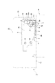
本発明に係る原稿圧着板開閉装置は、図1に示すように、事務機器(複写機以下同じ)1の機器本体1aの後端部に、原稿圧着板18を開閉可能に取り付けるものである。尚、原稿圧着板開閉装置は、通常一対設けられ、指示記号1Aと1Bとして示してある。実施例では指示記号1Bで示したものは、弾性手段が1本であるが、基本的な構成は1Aのものと同じである。しかしながら、同一構成のものであってもよいし、原稿圧着板開閉装置1Bは、原稿圧着板開閉装置1Aの動作を妨げなければ、弾性手段を有しない異なる構成のものであっても良い。以下の説明では指示記号1Aで示した原稿圧着板開閉装置のみについて説明する。
As shown in FIG. 1, a document crimping plate opening / closing apparatus according to the present invention is configured to attach a
原稿圧着板18の上部には、例えば、公知構成の原稿自動送り装置18aが設けられている。この原稿自動送り装置18aは、複数枚の原稿を効率よく複写したり送信したりするためのものである。この原稿自動送り装置18aは、原稿圧着板18の上部の一側に設けた図示してない原稿送り部を備え、この原稿送り部へ原稿をセットすると、自動的に原稿が順次送り出されて複写や送信が行えるように構成されている。
For example, an
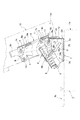
本発明に係る原稿圧着板開閉装置1Aは、図2以降に示したように、事務機器1の機器本体1a上に取り付けられた取付部材2に組み付けられた開閉機構Kとリフト機構Rとから構成されている。
The document pressing plate opening /
取付部材2は、例えばSPCCなどの金属板をプレス加工することにより構成したもので、機器本体1aに取り付けられる底板2aと、この底板2aの両側端部からそれぞれ当該底板2aに対して直交する方向(略直交する方向も含む。)に折り曲げた両側板2b、2bと、底板2aの一端部(後端部)から底板2aに対して直交する方向(略直交する方向も含む。)に折り曲げた略矩形状の後板2cとから成る。もちろん強度さえ出れば、合成樹脂の成形品であっても良い。
The
取付部材2は、とくに図7と図13に示したように、その底板2aに設けた平面ひょうたん形状の取付孔2eへ通した図示してない公知構成の取付釦を介して機器本体1a上へ着脱可能に取り付けられている。両側板2b、2bには、その後部上端に軸受孔10b、10bを有する軸受部材10c、10cを取り付ける第1取付孔2d、2dが設けられると共に、その前端部側には、後述するスプリングローシャフト9を介してスプリングケース3を取り付ける第2取付孔2f、2fが設けられている。この取付部材2の両側板2b、2bには、さらに、第1取付孔2d、2dと第2取付孔2f、2fの間に位置して半径は異なるが互いに連続している円弧状の第1ガイド溝2g、2gと第2ガイド溝2h、2hから成るガイド溝2i、2iが設けられており、さらに、後板2cには、ストッパー板19が取付ネジ19a、19aを介して取り付けられている。そして、第1ガイド溝2g、2gと第2ガイド溝2h、2hの連結部分には、交差部2j、2jが設けられている。
As shown in FIGS. 7 and 13, the mounting
まず、開閉機構Kの構成について説明する。この開閉機構Kは、取付部材2の両側板2b、2bの後部側に設けた第1取付孔2d、2dに取り付けた軸受部材10c、10cの軸受孔10b、10bに連結させたメインシャフト10を介して回転可能に取り付けられたアッパーアーム部材6と、このアッパーアーム部材6の自由端側に取り付けられたところの原稿圧着板18の支持部材8と、取付部材2の両側板2b、2bの前端部側にスプリングローシャフト9を介して揺動可能に取り付けられたスプリングケース3と、このスプリングケース3をスライド可能に収容し前記アッパーアーム部材6の両側板6b、6bの略中央部にスプリングアップシャフト11を介して揺動可能に取り付けられたスライダーケース4と、このスライダーケース4と前記スプリングケース3との間に弾設された弾性手段5とで構成されている。実施例1のものは、弾性手段5に大小の圧縮コイルスプリング5a、5a・5b、5bをそれぞれ重ねて用いている。
First, the configuration of the opening / closing mechanism K will be described. The opening / closing mechanism K includes a
スプリングケース3は、とくに図7と図14に示したように、例えばPOMなどの合成樹脂を成形することによって造った一端部開放の成形品であり、底部(以下先端部ともいう)側にスプリングローシャフト9へ揺動可能に連結する連結孔3aを有し、両側部にスリット3b、3bを有している。実施例のものは2連に並設した圧縮コイルスプリングからなる弾性手段を収容するために、スプリング収容部3cの形状は断面が略8の字形を呈しているが、1連の弾性手段を収容する形状にすることもできる。
As shown in FIGS. 7 and 14, the
スライダーケース4は、例えばSPCCなどの金属板をプレス加工して造ったもので、とくに図7と図15に示したように上板4aと、この上板4aの一端部側より下側に折り曲げた弾性手段5の当接プレート部4bと、上板4aの両側部より下側へ折り曲げた両側板4c、4cと、この両側板4c、4cの下端部より内側へ折り曲げて形成した拘持板4d、4d(とくに図15)とを有し、内部にスプリングケース3を摺動可能に収容させている。さらに、スライダーケース4の両側板4c、4cの先端部側には逃がし溝4e、4eが設けられていると共に、後端部側にはスプリングアップシャフト11を介してアッパーアーム部材6へ連結する連結孔4f、4fが設けられている。尚、このスライダーケース4は、例えば、POMその他の強度のある合成樹脂成型品とすることができる。
The
アッパーアーム部材6は、例えばSPCCなどの金属板をプレス加工して造ったもので、上板6aと、この上板6aの両側から下側へ折り曲げることによって形成した両側板6b、6bとを有し、とくに図7と図16に示したように、上板6aには、平面異形コの字形状の切欠部6dが設けられている。さらに、両側板6b、6bの下端部側には、メインシャフト10に連結する第1連結孔6e、6eと、後述するリフト機構Rのリンクアーム12、12のリンクシャフト15に連結する第2連結孔6f、6fが設けられ、略中央部にはスプリングアップシャフト11を連結する第3連結孔6g、6gが設けられ、上端部側には支持部材8に連結される第2リフトシャフト14に連結する第4連結孔6h、6hが設けられている。
The
支持部材8は、例えばSPCCなどの金属板をプレス加工して造ったもので、上板8aと、この上板8aの両側部より下側へ折り曲げられた両側板8b、8bと、この両側板8b、8bの下端部側より外側へ折り曲げられた原稿圧着板18の取付板8c、8cとを有しており、両側板8b、8bには、その上端部側に第2リフトシャフト14を連結する連結孔8d、8dと、後述する第1リフトシャフト13を連結する連結孔8e、8eが設けられている。
The
次に、リフト機構Rの構成について説明する。このリフト機構Rは、支持部材8と、この支持部材8へその上端部側を回転可能に連結したロワーアーム部材7と、このロワーアーム部材7の下端部側と前記アッパーアーム部材6の下端部側とを連結するリンクアーム12、12と、このリンクアーム12、12の前記アッパーアーム部材6の側に取り付けられ、前記取付部材2の両側板2b、2bに設けた第1ガイド溝2g、2gに嵌入されたガイド部材20を構成するところのローラシャフト16、16及びローラ17、17とで構成されている。尚、このガイド部材20は、ローラ17、17を省略してローラシャフト16、16のみとしても良い。
Next, the configuration of the lift mechanism R will be described. The lift mechanism R includes a
そして、アッパーアーム部材6と、ロワーアーム部材7と、アッパーアーム部材6とロワーアーム部材7の各下端部を連結するリンクアーム12、12と、アッパーアーム部材6とロワーアーム部材7の各先端自由端側に連結された支持部材8と、でリンク機構Lを構成している。即ち、リフト機構Rはリンク機構Lによって構成されていると言える。
The
ロワーアーム部材7は、例えばSPCCなどの金属板をプレス加工して造ったもので、上板7aにはとくに図15に示したように切欠部7cが設けられ、この上板7aの両側端より下方へ垂下させた両側板7b、7bには、その上端部側に第1リフトシャフト13を連結する連結孔7d、7dと、上述したように、ローラシャフト16を固定する固定孔7e、7eが前後方向へ位置をずらせて設けられている。尚、このロワーアーム部材7は、例えばPOMその他の強度のある合成樹脂製とすることができる。
The
リンクアーム12、12は、固定孔12a、12aと連結孔12b、12bを有し、固定孔12a、12aに取り付けたリンクシャフト15、15を介して、アッパーアーム部材6の第2連結孔6f、6fに固定されると共に、連結孔12b、12bに取り付けたローラシャフト16、16を介してロワーアーム部材7の固定孔7e、7eに連結されている。
The
選択動作手段Sは、リンクアーム12、12と、このリンクアーム12、12に取り付けたローラ17、17から成るガイド部材20と、このガイド部材20が嵌入している取付部材2の両側板2b、2bに設けた第1ガイド溝2g、2g及び第2ガイド溝2h、2hから成るガイド溝2i、2iとで構成されている。尚、ガイド部材20は、必ずしもローラ17、17としなくとも良いことは前述した。
The selection operation means S includes
次に、図面に指示記号16a、16aで示したものはローラシャフト16、16のワッシャーであり、指示記号16b、16bはスペーサーである。また、指示記号13a、13aと14a、14aで示されたものは、第1リフトシャフト13と第2リフトシャフト14のスペーサーである。さらに、指示記号11a、11aで示されたものはカラーである。また、スプリングローシャフト9は、一端部にフランジ部9aを有し、他端部を第2取付孔2f、2fの一方の側にかしめて固着される構成である。メインシャフト10も一端部にフランジ部10aを有し、軸受部材10c、10c内を貫通して他端部にワッシャー10dを嵌め込む構成である。このワッシャー10dは、Eリングであっても良い。さらに、スプリングアップシャフト11と、第1リフトシャフト13と第2リフトシャフト14にも一端部にフランジ部11b、13b、14bが設けられており、それぞれ他端部をかしめて連結孔4f、4f・8d、8d・8e、8eの一方の側にかしめて固定される構成である。勿論、かしめに代えてEリングその他の係止リングを用いても良い。
Next, what is indicated by
次に、上記原稿圧着板開閉装置1Aの作用効果について説明する。
Next, the function and effect of the
まず、図3と図8に示したように、複写機等の事務機器1の機器本体1aに対して原稿圧着板18を閉じた状態においては、当該原稿圧着板18はその重量でその下面をコンタクトガラス1b上に圧着しており、薄物原稿の場合には、当該薄物原稿をコンタクトガラス1b上へ圧着させる。また、この原稿圧着板開閉装置1Aの閉成時において、とくに図8に示したように、スライダーケース4、アッパーアーム部材6、ロワーアーム部材7、及び支持部材8は、取付部材2に対して互いに重なり合った状態にある。
First, as shown in FIGS. 3 and 8, when the
次に、この原稿圧着板18をその閉成状態から当該原稿圧着板18を開くべく、その手前側の取手部18b(図1に表示)に手を掛けて上方へ持ち上げると、まず、選択動作手段Sを介してリフト機構Rが動作して原稿圧着板18をコンタクトガラス1bに対して、図4と図9に示したように、水平に持ち上げることになる。
Next, in order to open the
つまり、原稿圧着板18の手前側の取手部18bに手を掛けて持ち上げると、リフト機構Rのリンク機構Lを構成する支持部材8とリンクアーム12、12により、アッパーアーム部材6とロワーアーム部材7が協動作用を行うため、支持部材8がコンタクトガラス1bに対して水平に持ち上がるので、この支持部材8に取り付けられている原稿圧着板18は同様に水平状態で持ち上がることになる。即ち、原稿圧着板18の手前側に手を掛けて持ち上げると、図8と図9に示したように、リンクアーム12、12が取付部材2のガイド溝2i、2iの第1ガイド溝2g、2gに嵌入しているローラ17、17を介して右方向へ旋回しつつ持ち上がり、アッパーアーム部材6とロワーアーム部材7を図中右方向へ回転させ、この回転により支持部材8が第1リフトシャフト13と第2リフトシャフト14を介して左方向へ旋回することにより、図4と図9に示したように、原稿圧着板18はコンタクトガラス1bに対して水平状態を維持した状態で持ち上がることになる。そして、所定の上昇位置で弾性手段5と原稿圧着板18の重量がバランスしたところで、原稿圧着板18は手を離しても自然落下することなく、水平開成状態を維持することができる。
That is, when the
原稿圧着板18が水平状態で所定の高さまで上昇すると、第1ガイド溝2g、2gに嵌入しているローラ17、17が当該第1ガイド溝2g、2gと第2ガイド溝2h、2hの交差部2j、2jに達するので、ここで原稿圧着板18の水平状態での上昇動作は終了する。
When the
この水平上昇状態から、さらに原稿圧着板18の手前側を上方へ持ち上げると、今度は選択動作手段Sを介して開閉機構Kが動作する。即ち、アッパーアーム部材6がメインシャフト10を支点に右方向へ回転する力を受け、ローラ17、17がガイド溝2i、2iの第2ガイド溝2h、2h内に嵌入し、アッパーアーム部材6の右方向の回転を許容される。すると、原稿圧着板18は水平上昇状態の高さを維持したまま支持部材8とともに回転することになり、図5と図10に示したように、原稿圧着板18は支持部材8と共にメインシャフト10を支点に回転して開かれることになる。そうすると、弾性手段5の弾力はスライダーケース4を介して支持部材8に作用していることから、原稿圧着板18はその重量を余り感じさせることなく開かれることになり、弾性手段5の弾力と原稿圧着板18の重量がバランスしたところで、原稿圧着板18より手を離しても自然に落下して閉じられてしまうことはない。
When the front side of the
したがって、原稿圧着板18の回転モーメントは、所定の開成角度範囲において弾性手段5の弾力とバランスするので、原稿圧着板18より手を離しても自然落下しない開成使用角度において、両手を用いてコンタクトガラス1b上へ原稿を載置したり、交換したりすることが可能となる。
Accordingly, the rotational moment of the
もとより、ここのところは、一方の手で原稿圧着板18を開いた状態で保持させていて、もう一方の手で原稿を交換するようにしても良い。
Of course, here, the
コンタクトガラス1b上へ原稿を載置するか、原稿を複写し終わって原稿をコンタクトガラス1b上より取り去って、原稿圧着板18の手前側の取手部18bを下方へ手で押すと、リンク機構Lによってリフト機構Rは動作せず、ローラ17、17が第2ガイド溝2h、2h内を先ほどとは逆方向へ転動して開閉機構Kにより原稿圧着板18は元の水平状態まで閉じられる。図4と図9に示した上昇時の水平状態に戻ったところで、今度はリフト機構Rが動作して原稿圧着板18はコンタクトガラス1bに対して水平状態で閉じられることになる。
When the original is placed on the
したがって、図4と図9に示したように、コンタクトガラス1b上に複写すべき薄物原稿がある時に原稿圧着板18を閉じても、当該原稿圧着板18が水平状態で閉じられるので、薄物原稿に斜めからの風が当たり位置ずれが生ずるのを防止することができるものである。
Therefore, as shown in FIGS. 4 and 9, even if the
他方、原稿が本のように厚い厚物原稿Gの場合には、原稿圧着板18が水平状態で持ち上がった状態で厚物原稿Gをコンタクトガラス1b上へ載置させ、原稿圧着板18を閉じると、当該原稿圧着板18は水平状態に閉じられるため、従来技術のもののように、原稿圧着板を弾性手段の弾力に抗して反転させる必要がないので、不必要な力を必要としないことから操作性が向上し、かつ、コンタクトガラスに無理な押圧力が加わることがないものである。
On the other hand, when the original is a thick original G such as a book, the thick original G is placed on the
図12は、原稿圧着板18をさらに開いた状態を示し、このように原稿圧着板18を開いても、当該原稿圧着板18の後部が不必要に事務機器1の後方へ突出することがないので、壁際へ事務機器1を設置する際の後部スペースを省略できる。
FIG. 12 shows a state in which the
以上説明したように、本発明に係る原稿圧着板開閉装置は、複写機、印刷機、プリンター等の事務機器の原稿圧着板や、複写機能の他にプリンター、ファクシミリ、スキャナー等の各種機能を有する所謂複合機と称せられる事務機器の原稿圧着板若しくはADF装置(自動原稿送り装置)付の原稿圧着板を開閉する開閉装置として好適に用いられ、また、本発明に係る原稿圧着板開閉装置を用いた事務機器としても有用性を持つものである。 As described above, the document crimping plate opening / closing device according to the present invention has various functions such as a document crimping plate for office equipment such as a copying machine, a printing machine, and a printer, a printer, a facsimile machine, a scanner, etc. in addition to a copying function. It is suitably used as an opening / closing device for opening / closing a document crimping plate of an office machine called a so-called multi-function machine or a document crimping plate with an ADF device (automatic document feeder), and the document crimping plate opening / closing device according to the present invention is used. It is also useful as office equipment.
1A、1B 原稿圧着板開閉装置
K 開閉機構
L リンク機構
R リフト機構
S 選択動作手段
1 事務機器
1a 機器本体
2 取付部材
2b、4c、6b、7b、8b 両側板
2g 第1ガイド溝
2h 第2ガイド溝
2i ガイド溝
3 スプリングケース
4 スライダーケース
5 弾性手段
5a、5b 圧縮コイルスプリング
6 アッパーアーム部材
7 ロワーアーム部材
8 支持部材
9 スプリングローシャフト
10 メインシャフト
11 スプリングアップシャフト
12 リンクアーム
17 ローラ
18 原稿圧着板
20 ガイド部材
1A, 1B Document Crimping Plate Opening / Closing Device K Opening / Closing Mechanism L Link Mechanism R Lift Mechanism S
Claims (5)
前記開閉機構は、前記取付部材の両側板の後部側にメインシャフトを介して回転可能に取り付けられたアッパーアーム部材と、このアッパーアーム部材の両側板の自由端側に取り付けられたところの前記原稿圧着板の支持部材と、前記取付部材の前記両側板の前部側にスプリングローシャフトを介して揺動可能に取り付けられたスプリングケースと、このスプリングケースをスライド可能に収容し前記アッパーアーム部材の両側板の略中央部にスプリングアップシャフトを介して揺動可能に取り付けられたスライダーケースと、このスライダーケースと前記スプリングケースとの間に弾設された弾性手段と、で構成し、
前記リフト機構は、その上端部側を前記支持部材へ回転可能に連結したロワーアーム部材と、このロワーアーム部材の下端部側と前記アッパーアーム部材の下端部側とを連結するリンクアームとから成るリンク機構で構成し、
前記選択動作手段は、前記開閉機構の前記取付部材に設けた第1ガイド溝と第2ガイド溝からなるガイド溝と、これらの各ガイド溝に嵌入させたところの前記リフト機構を構成するリンクアームに取り付けられ、前記ガイド溝に嵌入されたローラシャフトに取り付けたローラとから成るガイド部材とで構成し、
前記選択動作手段により、前記リフト機構による前記原稿圧着板の水平状態での上昇動作終了時より前記開閉機構が動作し、前記開閉機構の閉成動作終了時より前記リフト機構が水平状態で前記原稿圧着板を降下させるように構成したことを特徴とする、原稿圧着板開閉装置。 An open / close mechanism of a document crimping plate assembled to an attachment member attached to an apparatus main body of office equipment, a lift mechanism, a selection operation means for selecting an operation of the open / close mechanism and the lift mechanism,
The opening / closing mechanism includes an upper arm member rotatably attached to the rear side of both side plates of the attachment member via a main shaft, and the document attached to the free end side of the both side plates of the upper arm member A support member for the crimping plate, a spring case attached to the front side of the both side plates of the attachment member via a spring low shaft, and a slidably received spring member for accommodating the upper arm member. A slider case attached to a substantially central portion of both side plates via a spring-up shaft so as to be swingable, and an elastic means elastically provided between the slider case and the spring case.
The lift mechanism includes a lower arm member whose upper end portion is rotatably connected to the support member, and a link mechanism that connects a lower end portion side of the lower arm member and a lower end portion side of the upper arm member. Consisting of
The selection operation means includes a guide groove including a first guide groove and a second guide groove provided on the attachment member of the opening / closing mechanism, and a link arm constituting the lift mechanism when fitted in each of the guide grooves. And a guide member consisting of a roller attached to a roller shaft fitted in the guide groove,
The selection operation means operates the opening / closing mechanism from the end of the lifting operation of the document pressing plate in the horizontal state by the lift mechanism, and the document in the horizontal state from the end of the closing operation of the opening / closing mechanism. A document crimping plate opening and closing device, characterized in that the crimping plate is lowered .
Priority Applications (4)
| Application Number | Priority Date | Filing Date | Title |
|---|---|---|---|
| JP2010160476A JP5811433B2 (en) | 2010-07-15 | 2010-07-15 | Document crimping plate opening and closing device and office equipment |
| CN201110196759.8A CN102338997B (en) | 2010-07-15 | 2011-07-14 | Opening-closing device of manuscript pressing plate and office machine |
| TW100124941A TWI441988B (en) | 2010-07-15 | 2011-07-14 | Opening-closing device of copy pressing plate and office machine |
| KR1020110070360A KR101341690B1 (en) | 2010-07-15 | 2011-07-15 | Opening-closing device of manuscript pressing plate and office machine |
Applications Claiming Priority (1)
| Application Number | Priority Date | Filing Date | Title |
|---|---|---|---|
| JP2010160476A JP5811433B2 (en) | 2010-07-15 | 2010-07-15 | Document crimping plate opening and closing device and office equipment |
Publications (3)
| Publication Number | Publication Date |
|---|---|
| JP2012022175A JP2012022175A (en) | 2012-02-02 |
| JP2012022175A5 JP2012022175A5 (en) | 2013-08-29 |
| JP5811433B2 true JP5811433B2 (en) | 2015-11-11 |
Family
ID=45514795
Family Applications (1)
| Application Number | Title | Priority Date | Filing Date |
|---|---|---|---|
| JP2010160476A Expired - Fee Related JP5811433B2 (en) | 2010-07-15 | 2010-07-15 | Document crimping plate opening and closing device and office equipment |
Country Status (4)
| Country | Link |
|---|---|
| JP (1) | JP5811433B2 (en) |
| KR (1) | KR101341690B1 (en) |
| CN (1) | CN102338997B (en) |
| TW (1) | TWI441988B (en) |
Families Citing this family (5)
| Publication number | Priority date | Publication date | Assignee | Title |
|---|---|---|---|---|
| TWI527975B (en) | 2012-12-14 | 2016-04-01 | 緯創資通股份有限公司 | Rotary mechanism and related electronic device |
| JP6128585B2 (en) * | 2013-02-13 | 2017-05-17 | 株式会社ナチュラレーザ・ワン | Document crimping plate opening / closing device and office equipment provided with this document crimping plate opening / closing device |
| JP6492344B2 (en) * | 2015-01-26 | 2019-04-03 | 下西技研工業株式会社 | Hinge |
| JP6601905B2 (en) * | 2015-08-21 | 2019-11-06 | 株式会社ナチュラレーザ・ワン | Open / close support device and various devices using the open / close support device |
| JP6819998B2 (en) * | 2016-10-31 | 2021-01-27 | 株式会社ナチュラレーザ・ワン | Door body opening / closing device and various cabinets equipped with this door body opening / closing device |
Family Cites Families (10)
| Publication number | Priority date | Publication date | Assignee | Title |
|---|---|---|---|---|
| JPS6026331A (en) * | 1983-07-22 | 1985-02-09 | Fuji Xerox Co Ltd | Original pressing device of copying machine or the like |
| JPS6141242U (en) * | 1984-08-21 | 1986-03-15 | 富士ゼロックス株式会社 | Original holding device in the book handler of a copying machine |
| JPH11125056A (en) * | 1997-10-22 | 1999-05-11 | Nisca Corp | Hinge device |
| JP3899213B2 (en) * | 1999-11-30 | 2007-03-28 | 加藤電機株式会社 | Document crimping plate opening and closing device |
| JP3584242B2 (en) * | 2002-03-20 | 2004-11-04 | 下西技研工業株式会社 | Document pressure plate opening and closing device |
| JP4794144B2 (en) * | 2004-06-24 | 2011-10-19 | 加藤電機株式会社 | Document crimping plate opening and closing device |
| JP4636826B2 (en) * | 2004-07-30 | 2011-02-23 | 下西技研工業株式会社 | Document crimping plate opening and closing device |
| JP4351597B2 (en) * | 2004-08-02 | 2009-10-28 | 加藤電機株式会社 | Document crimping plate opening and closing device |
| JP2007150848A (en) * | 2005-11-29 | 2007-06-14 | Seiko Epson Corp | Scanner |
| JP5441097B2 (en) * | 2008-12-09 | 2014-03-12 | 株式会社ナチュラレーザ・ワン | Document crimping plate opening and closing device and office equipment |
-
2010
- 2010-07-15 JP JP2010160476A patent/JP5811433B2/en not_active Expired - Fee Related
-
2011
- 2011-07-14 TW TW100124941A patent/TWI441988B/en not_active IP Right Cessation
- 2011-07-14 CN CN201110196759.8A patent/CN102338997B/en not_active Expired - Fee Related
- 2011-07-15 KR KR1020110070360A patent/KR101341690B1/en not_active IP Right Cessation
Also Published As
| Publication number | Publication date |
|---|---|
| TW201209299A (en) | 2012-03-01 |
| CN102338997B (en) | 2014-12-31 |
| KR20120008000A (en) | 2012-01-25 |
| CN102338997A (en) | 2012-02-01 |
| TWI441988B (en) | 2014-06-21 |
| JP2012022175A (en) | 2012-02-02 |
| KR101341690B1 (en) | 2013-12-13 |
Similar Documents
| Publication | Publication Date | Title |
|---|---|---|
| JP5811433B2 (en) | Document crimping plate opening and closing device and office equipment | |
| JP5645210B2 (en) | Document crimping plate opening and closing device | |
| JP5966164B2 (en) | Document crimping plate opening and closing device and office equipment | |
| JP5429767B2 (en) | Document crimping plate opening and closing device and office equipment equipped with document crimping plate | |
| KR101241616B1 (en) | Opening-closing device of manuscript pressing plate and office machine | |
| JP5807943B2 (en) | Document crimping plate opening and closing device and office equipment | |
| JP2006139008A (en) | Original pressing plate opening/closing apparatus, and business machine with the same | |
| JP2011227370A5 (en) | ||
| JP5223070B2 (en) | Document crimping plate opening and closing device | |
| KR101435728B1 (en) | Opening-closing maintenance device of manuscript pressing plate and office machine using the device | |
| JP5995046B2 (en) | Document crimping plate opening and closing device and OA equipment | |
| CN106468871B (en) | Opening and closing support device and equipment with same | |
| JP6128585B2 (en) | Document crimping plate opening / closing device and office equipment provided with this document crimping plate opening / closing device | |
| JP2013020191A5 (en) | ||
| JP4898216B2 (en) | Document crimping plate opening and closing device and office equipment | |
| US20100125971A1 (en) | Hinge device for use in office machine | |
| JP2020106742A (en) | Document pressing plate opening/closing device and business machine with document pressing plate opening/closing device | |
| JP5217002B2 (en) | Document crimping plate opening and closing device | |
| KR0125530Y1 (en) | Opening and closing device of document pressing plate | |
| JP2006255979A (en) | Image forming device | |
| JP7025009B2 (en) | Elevating device for lid and various devices | |
| JP2022085726A (en) | Hinge and office machine using this hinge | |
| JP2023077954A (en) | Insertion hinge, and office machine using the same | |
| JP2022085726A5 (en) | ||
| JP3939920B2 (en) | Pressure plate opening / closing mechanism of scanner device and scanner device |
Legal Events
| Date | Code | Title | Description |
|---|---|---|---|
| A711 | Notification of change in applicant |
Free format text: JAPANESE INTERMEDIATE CODE: A711 Effective date: 20130207 |
|
| A521 | Written amendment |
Free format text: JAPANESE INTERMEDIATE CODE: A523 Effective date: 20130712 |
|
| A621 | Written request for application examination |
Free format text: JAPANESE INTERMEDIATE CODE: A621 Effective date: 20130712 |
|
| A977 | Report on retrieval |
Free format text: JAPANESE INTERMEDIATE CODE: A971007 Effective date: 20140421 |
|
| A131 | Notification of reasons for refusal |
Free format text: JAPANESE INTERMEDIATE CODE: A131 Effective date: 20140603 |
|
| A521 | Written amendment |
Free format text: JAPANESE INTERMEDIATE CODE: A523 Effective date: 20140804 |
|
| A131 | Notification of reasons for refusal |
Free format text: JAPANESE INTERMEDIATE CODE: A131 Effective date: 20150113 |
|
| A521 | Written amendment |
Free format text: JAPANESE INTERMEDIATE CODE: A523 Effective date: 20150316 |
|
| TRDD | Decision of grant or rejection written | ||
| A01 | Written decision to grant a patent or to grant a registration (utility model) |
Free format text: JAPANESE INTERMEDIATE CODE: A01 Effective date: 20150818 |
|
| A61 | First payment of annual fees (during grant procedure) |
Free format text: JAPANESE INTERMEDIATE CODE: A61 Effective date: 20150903 |
|
| R150 | Certificate of patent or registration of utility model |
Ref document number: 5811433 Country of ref document: JP Free format text: JAPANESE INTERMEDIATE CODE: R150 |
|
| LAPS | Cancellation because of no payment of annual fees |