JP2013155408A - Method for manufacturing water repellent film and water repellent film manufactured by the manufacturing method - Google Patents
Method for manufacturing water repellent film and water repellent film manufactured by the manufacturing method Download PDFInfo
- Publication number
- JP2013155408A JP2013155408A JP2012016924A JP2012016924A JP2013155408A JP 2013155408 A JP2013155408 A JP 2013155408A JP 2012016924 A JP2012016924 A JP 2012016924A JP 2012016924 A JP2012016924 A JP 2012016924A JP 2013155408 A JP2013155408 A JP 2013155408A
- Authority
- JP
- Japan
- Prior art keywords
- film
- water
- temperature
- repellent
- film formation
- Prior art date
- Legal status (The legal status is an assumption and is not a legal conclusion. Google has not performed a legal analysis and makes no representation as to the accuracy of the status listed.)
- Granted
Links
Images


Classifications
-
- B—PERFORMING OPERATIONS; TRANSPORTING
- B05—SPRAYING OR ATOMISING IN GENERAL; APPLYING FLUENT MATERIALS TO SURFACES, IN GENERAL
- B05D—PROCESSES FOR APPLYING FLUENT MATERIALS TO SURFACES, IN GENERAL
- B05D1/00—Processes for applying liquids or other fluent materials
- B05D1/60—Deposition of organic layers from vapour phase
-
- B—PERFORMING OPERATIONS; TRANSPORTING
- B05—SPRAYING OR ATOMISING IN GENERAL; APPLYING FLUENT MATERIALS TO SURFACES, IN GENERAL
- B05D—PROCESSES FOR APPLYING FLUENT MATERIALS TO SURFACES, IN GENERAL
- B05D5/00—Processes for applying liquids or other fluent materials to surfaces to obtain special surface effects, finishes or structures
- B05D5/08—Processes for applying liquids or other fluent materials to surfaces to obtain special surface effects, finishes or structures to obtain an anti-friction or anti-adhesive surface
-
- B—PERFORMING OPERATIONS; TRANSPORTING
- B41—PRINTING; LINING MACHINES; TYPEWRITERS; STAMPS
- B41J—TYPEWRITERS; SELECTIVE PRINTING MECHANISMS, i.e. MECHANISMS PRINTING OTHERWISE THAN FROM A FORME; CORRECTION OF TYPOGRAPHICAL ERRORS
- B41J2/00—Typewriters or selective printing mechanisms characterised by the printing or marking process for which they are designed
- B41J2/005—Typewriters or selective printing mechanisms characterised by the printing or marking process for which they are designed characterised by bringing liquid or particles selectively into contact with a printing material
- B41J2/01—Ink jet
- B41J2/135—Nozzles
- B41J2/14—Structure thereof only for on-demand ink jet heads
- B41J2/14201—Structure of print heads with piezoelectric elements
- B41J2/14233—Structure of print heads with piezoelectric elements of film type, deformed by bending and disposed on a diaphragm
-
- B—PERFORMING OPERATIONS; TRANSPORTING
- B41—PRINTING; LINING MACHINES; TYPEWRITERS; STAMPS
- B41J—TYPEWRITERS; SELECTIVE PRINTING MECHANISMS, i.e. MECHANISMS PRINTING OTHERWISE THAN FROM A FORME; CORRECTION OF TYPOGRAPHICAL ERRORS
- B41J2/00—Typewriters or selective printing mechanisms characterised by the printing or marking process for which they are designed
- B41J2/005—Typewriters or selective printing mechanisms characterised by the printing or marking process for which they are designed characterised by bringing liquid or particles selectively into contact with a printing material
- B41J2/01—Ink jet
- B41J2/135—Nozzles
- B41J2/16—Production of nozzles
- B41J2/1606—Coating the nozzle area or the ink chamber
-
- B—PERFORMING OPERATIONS; TRANSPORTING
- B05—SPRAYING OR ATOMISING IN GENERAL; APPLYING FLUENT MATERIALS TO SURFACES, IN GENERAL
- B05D—PROCESSES FOR APPLYING FLUENT MATERIALS TO SURFACES, IN GENERAL
- B05D1/00—Processes for applying liquids or other fluent materials
- B05D1/18—Processes for applying liquids or other fluent materials performed by dipping
- B05D1/185—Processes for applying liquids or other fluent materials performed by dipping applying monomolecular layers
-
- B—PERFORMING OPERATIONS; TRANSPORTING
- B41—PRINTING; LINING MACHINES; TYPEWRITERS; STAMPS
- B41J—TYPEWRITERS; SELECTIVE PRINTING MECHANISMS, i.e. MECHANISMS PRINTING OTHERWISE THAN FROM A FORME; CORRECTION OF TYPOGRAPHICAL ERRORS
- B41J2202/00—Embodiments of or processes related to ink-jet or thermal heads
- B41J2202/01—Embodiments of or processes related to ink-jet heads
- B41J2202/03—Specific materials used
Abstract
Description
本発明は、撥水膜の製造方法および該製造方法により製造された撥水膜に係り、特に、蒸着法を用いた撥水膜の製造方法および該製造方法により製造された撥水膜に関する。 The present invention relates to a water repellent film manufacturing method and a water repellent film manufactured by the manufacturing method, and more particularly to a water repellent film manufacturing method using a vapor deposition method and a water repellent film manufactured by the manufacturing method.
インクジェット記録装置で用いられるインクジェットヘッドでは、ノズルプレートの表面にインクが付着していると、ノズルから吐出されるインク液滴が影響を受けて、インク液滴の吐出方向にばらつきが生じることがある。インクが付着すると、記録媒体上の所定位置にインクを着弾させることが困難になり、画像品質が劣化する原因となる。 In an ink jet head used in an ink jet recording apparatus, if ink adheres to the surface of a nozzle plate, ink droplets ejected from the nozzles are affected, and the ink droplet ejection direction may vary. . When the ink adheres, it becomes difficult to land the ink at a predetermined position on the recording medium, which causes the image quality to deteriorate.
そこで、ノズルプレート表面にインクが付着することを防止し吐出性能を向上させるため、ノズルプレート表面に撥水膜を形成することが提案されている。 Therefore, in order to prevent ink from adhering to the surface of the nozzle plate and improve the discharge performance, it has been proposed to form a water repellent film on the surface of the nozzle plate.
高密着の撥水材料として、シランカップリング剤の撥水コートが知られている。シランカップリング剤の撥水膜の形成方法は、従来は、シランカップリング材料を、フッ素溶媒に溶解して0.1wt%程度の濃度に調整し、当該溶液に基板を浸漬して引き上げ、乾燥させるディップ法が一般的であった。 A water-repellent coat of a silane coupling agent is known as a highly adhesive water-repellent material. A method for forming a water-repellent film of a silane coupling agent has been conventionally achieved by dissolving a silane coupling material in a fluorine solvent to adjust the concentration to about 0.1 wt%, immersing the substrate in the solution, pulling it up, and drying. The dip method to make was common.
しかしながら、近年、撥水膜を成膜するにあたり、撥水膜の成膜を行いたい基板に耐溶剤性がないために、溶液に浸漬することができない場合が多くある。このような場合は、シランカップリング材料を気相法(蒸着法)により成膜することが一般的である。 However, in recent years, in forming a water-repellent film, the substrate on which the water-repellent film is to be formed is often not able to be immersed in a solution because of lack of solvent resistance. In such a case, the silane coupling material is generally formed by a vapor phase method (evaporation method).
例えば、下記の特許文献1〜4には、フッ素系撥水材料を気相成膜によって成膜する方法が開示されている。 For example, Patent Documents 1 to 4 below disclose a method of forming a fluorine-based water repellent material by vapor phase film formation.
また、インクジェットヘッドのノズル面は、吐出安定性を維持するため、ワイピングを行なう必要があるが、ワイピングなどでノズル面を擦ると余剰に撥水材料が付与されていると容易に撥水材料が取れてしまうため、ノズルを詰まらせるという問題があった。そのため、下記の特許文献4においては、ノズル面に凹部を設け、余分な撥水材料が凹部に溜まるような構成とし、ノズル内部が詰まることを防止していた。また、特許文献5では、結合の弱い撥水材料を予め粘着テープによって除去することが開示されている。 In addition, the nozzle surface of the inkjet head needs to be wiped in order to maintain ejection stability. However, when the nozzle surface is rubbed by wiping or the like, excessive water-repellent material is easily applied. As a result, the nozzle was clogged. Therefore, in the following Patent Document 4, a concave portion is provided on the nozzle surface so that excess water-repellent material is accumulated in the concave portion to prevent clogging inside the nozzle. Patent Document 5 discloses that a water-repellent material having a weak bond is previously removed with an adhesive tape.
しかしながら、特許文献1および2に記載されている成膜方法の成膜温度は100℃程度である。特許文献1および2で用いられているパーフルオロポリエーテルを有するフッ素化合物のような分子量の大きい撥水材料は、TG−DTA測定により、300〜600℃でゆっくりと揮発することが知られている。したがって、100℃程度では、温度が低いため撥水材料の蒸気圧が非常に低く、成膜時間が長くなり、特許文献1においては、成膜に2時間かかっていた。 However, the film formation temperature of the film formation methods described in Patent Documents 1 and 2 is about 100 ° C. It is known that a water repellent material having a large molecular weight such as a fluorine compound having a perfluoropolyether used in Patent Documents 1 and 2 slowly volatilizes at 300 to 600 ° C. by TG-DTA measurement. . Therefore, at about 100 ° C., since the temperature is low, the vapor pressure of the water repellent material is very low, and the film formation time becomes long. In Patent Document 1, the film formation takes 2 hours.
また、特許文献3は、加熱原の出力を調整して成膜(蒸着)しており、水晶振動子によって膜厚を制御しているが、単分子膜は10〜80Å程度であり、制御が極めて困難であった。さらに、撥水材料が突沸したとの記載もあり、このような高温の成膜では、成膜の制御が困難であった。特許文献4は、撥水材料であるオプツールDSXを400℃程度で成膜することが記載されているが、常温〜200℃で成膜することが可能であることも記載されており、撥水材料の適切な揮発温度は明確にされていなかった。 Patent Document 3 forms a film (evaporation) by adjusting the output of the heating source, and the film thickness is controlled by a crystal resonator. It was extremely difficult. Furthermore, there is a description that the water-repellent material has bumped, and it has been difficult to control the film formation in such a high temperature film formation. Patent Document 4 describes that the film of OPTOOL DSX, which is a water repellent material, is formed at about 400 ° C., but it is also described that the film can be formed at room temperature to 200 ° C. The proper volatilization temperature of the material has not been defined.
また、特許文献4においては、余分な撥水材料が溜まるように凹部を設けているが、凹部を形成するには、コストアップにつながり、また、凹部で防ぎきれなかった余分な撥水材料はノズルを詰まらせヘッドの寿命を短くさせるという問題があった。特許文献5においては、粘着テープにより結合の弱い撥水材料の除去を行なっているが、この方法では、本来結合している撥水膜まで剥がれてしまう可能性があり、また、粘着テープの粘着剤が撥水膜上に残り撥水性が低下する、条件によっては十分に撥水材料が取れないという問題があった。 Further, in Patent Document 4, a concave portion is provided so that excess water-repellent material is accumulated. However, forming the concave portion leads to an increase in cost, and the extra water-repellent material that could not be prevented by the concave portion is There is a problem that the nozzle is clogged and the life of the head is shortened. In Patent Document 5, the water-repellent material that is weakly bonded is removed by the adhesive tape. However, in this method, the water-repellent film that is originally bonded may be peeled off. There is a problem that the agent remains on the water-repellent film and the water repellency is lowered, and the water-repellent material cannot be sufficiently removed depending on the conditions.
さらに、特許文献3は、水晶振動子に付着した膜材料の重量を測定して膜厚の制御を行なっている。また、膜厚の測定としては、XRR(X線反射率)により測定することができる。しかしながら、撥水膜は、単分子構造の膜を基本としており、例えば、XRRにより測定した場合、余分な撥水材料が付着した膜、付着していない膜においても、同じ膜厚の膜として検出される。これは、余分に撥水材料が付着した膜は、XRR測定により検出される単分子膜と、X線の回折が得られない分子の向きが乱れた余分な撥水材料の付着という構造になっているからであると考えられる。特許文献3に記載されている方法で膜厚の制御を行なっても、単分子膜の形成、または、余剰の撥水材料の付着のいずれが生じているかわからず、余剰の撥水材料は、容易に剥がれ、ノズル詰まりの原因になると考えられる。 Further, Patent Document 3 controls the film thickness by measuring the weight of the film material attached to the crystal resonator. The film thickness can be measured by XRR (X-ray reflectivity). However, the water-repellent film is basically a film having a monomolecular structure. For example, when measured by XRR, a film with an excess water-repellent material attached and a film without an attached film are detected as the same film thickness. Is done. This is because the film with extra water-repellent material attached has a structure of a monomolecular film detected by XRR measurement and extra water-repellent material attached with disordered orientation of molecules for which X-ray diffraction cannot be obtained. It is thought that it is because. Even if the film thickness is controlled by the method described in Patent Document 3, it is not known whether the formation of a monomolecular film or the adhesion of an excessive water repellent material has occurred. It can be easily peeled off and cause nozzle clogging.
本発明はこのような事情に鑑みてなされたものであり、薬液耐性・ワイプ耐性に優れた撥水膜の製造方法および該製造方法により製造された撥水膜を提供することを目的とする。 This invention is made | formed in view of such a situation, and it aims at providing the manufacturing method of the water-repellent film excellent in chemical | medical solution resistance and wipe resistance, and the water-repellent film manufactured by this manufacturing method.
本発明は前記目的を達成するために、基板上に、シランカップリング剤により有機膜を蒸着法により被覆する有機膜被覆工程と、有機膜被覆工程における成膜条件を、前記基板と同じ材料を用いて、予め決定する成膜条件決定工程と、を有し、成膜条件決定工程は、シランカップリング剤が、蒸発する温度以上突沸が起こらない温度以下に決定する温度決定工程と、温度決定工程で決定した温度において、有機膜を被覆し、光学顕微鏡観察により玉状の余剰撥水材料が形成される時間を測定し、前記時間より短い時間を成膜時間と決定する成膜時間決定工程と、からなる撥水膜の製造方法を提供する。 In order to achieve the above object, the present invention provides an organic film coating step for coating an organic film on a substrate by a vapor deposition method with a silane coupling agent, and the film formation conditions in the organic film coating step are the same as those for the substrate. A film forming condition determining step that is determined in advance, and the film forming condition determining step includes a temperature determining step that determines a temperature at which the silane coupling agent evaporates to a temperature that does not cause bumping, and a temperature determining step. A film formation time determining step of covering the organic film at the temperature determined in the process, measuring the time during which the ball-shaped surplus water-repellent material is formed by optical microscope observation, and determining a time shorter than the time as the film formation time And a method for producing a water repellent film comprising:
本発明によれば、有機膜被覆工程における蒸着法の成膜条件を、同様の材料を用いて別途成膜を行い、最適な成膜温度、成膜時間を決定した後、有機膜の被覆を行っているので、ワイプ耐性、インク浸漬耐性に優れた密度の高い単分子膜を形成することができる。また、余分な撥水材料を蒸着させることがないので、高価な撥水材料の使用を低減することができ、また、単分子膜表面に余剰の撥水材料が形成されることがなく、余剰の撥水材料は剥離しやすいため、ノズル詰まりの原因を防止することができる。 According to the present invention, the film formation conditions of the vapor deposition method in the organic film coating step are separately formed using the same material, and after determining the optimum film formation temperature and film formation time, the organic film is coated. As a result, it is possible to form a high-density monomolecular film excellent in wipe resistance and ink immersion resistance. Further, since no extra water-repellent material is deposited, the use of expensive water-repellent material can be reduced, and no excessive water-repellent material is formed on the surface of the monomolecular film. Since the water repellent material is easy to peel off, the cause of nozzle clogging can be prevented.
本発明の他の態様に係る撥水膜の製造方法は、温度決定工程により決定される温度は、10℃/minの速度で昇温して得られたTG−DTA測定で、重量減少が10%以上90%以下であることが好ましい。 In the method for producing a water-repellent film according to another aspect of the present invention, the temperature determined by the temperature determination step is TG-DTA measurement obtained by increasing the temperature at a rate of 10 ° C./min, and the weight loss is 10 % Or more and 90% or less is preferable.
本発明の他の態様に係る撥水膜の製造方法によれば、TG−DTAで測定したデータの重量減少が10%以上90%以下の温度とすることで、シランカップリング剤の揮発する温度で成膜を行なうことができる。 According to the method for producing a water-repellent film according to another aspect of the present invention, the temperature at which the weight loss of data measured by TG-DTA is 10% or more and 90% or less, whereby the temperature at which the silane coupling agent volatilizes. The film can be formed by
本発明の他の態様に係る撥水膜の製造方法は、成膜時間決定工程は、成膜物の静的接触角を測定し、静的接触角が110°以上になる時間以上に決定することが好ましい。 In the method for producing a water-repellent film according to another aspect of the present invention, the film formation time determining step measures the static contact angle of the film-formed material and determines the static contact angle to be equal to or longer than 110 °. It is preferable.
本発明の他の態様に係る撥水膜の製造方法によれば、成膜時間決定工程により、静的接触角が110°以上になる時間まで成膜を行なっているので、十分な撥水性を付与することができる。 According to the method for producing a water-repellent film according to another aspect of the present invention, the film is formed until the static contact angle reaches 110 ° or more in the film formation time determination step. Can be granted.
本発明の他の態様に係る撥水膜の製造方法は、成膜時間決定工程は、玉状の余剰撥水材料が形成される時間の直前を成膜時間と決定することが好ましい。 In the method for producing a water-repellent film according to another aspect of the present invention, the film formation time determining step preferably determines the film formation time immediately before the time when the ball-shaped surplus water-repellent material is formed.
本発明の他の態様に係る撥水膜の製造方法によれば、余剰撥水材料が形成される直前の時間を成膜時間としているので、余剰撥水材料が形成されることがなく、また、余剰撥水材料が形成される直前まで成膜をすることで、単分子膜を高い密度で成膜することができるので、ワイプ耐性、インク浸漬耐性を向上させることができる。 According to the method for producing a water-repellent film according to another aspect of the present invention, since the time immediately before the formation of the excess water-repellent material is used as the film formation time, the excess water-repellent material is not formed, and Since the monomolecular film can be formed at a high density by performing the film formation until immediately before the excessive water repellent material is formed, the wipe resistance and the ink immersion resistance can be improved.
本発明の他の態様に係る撥水膜の製造方法は、温度決定工程により決定される温度は、TG−DTA測定による重量減少が20%以上80%以下であることが好ましい。 In the method for producing a water-repellent film according to another aspect of the present invention, it is preferable that the temperature determined by the temperature determining step is 20% or more and 80% or less by weight reduction by TG-DTA measurement.
本発明の他の態様に係る撥水膜の製造方法によれば、温度決定工程により決定する温度を、TG−DTA測定による重量減少が20%以上80%以下の温度としているので、シランカップリング剤が揮発しやすく、そして、基板に蒸着しやすい条件とすることができるので、形成される撥水膜の制御を行いやすくすることができる。 According to the method for producing a water-repellent film according to another aspect of the present invention, the temperature determined by the temperature determination step is a temperature at which weight loss by TG-DTA measurement is 20% or more and 80% or less. Since the agent can easily evaporate and can be easily deposited on the substrate, the formed water-repellent film can be easily controlled.
本発明の他の態様に係る撥水膜の製造方法は、有機膜を成膜した後、使用前に所定の時間、保管する保管工程と、を有することが好ましい。 The method for producing a water-repellent film according to another aspect of the present invention preferably includes a storage step of storing an organic film for a predetermined time before use after forming the organic film.
本発明の他の態様に係る撥水膜の製造方法によれば、有機膜を成膜した後、所定の時間保管を行なう保管工程を有することで、基板と有機膜の密着性を向上させることができる。 According to the method for producing a water-repellent film according to another aspect of the present invention, the adhesion between the substrate and the organic film is improved by having a storage step of storing the organic film for a predetermined time after forming the organic film. Can do.
本発明の他の態様に係る撥水膜の製造方法は、保管工程は、温度および湿度を制御して行なうことが好ましい。 In the method for producing a water-repellent film according to another aspect of the present invention, the storage step is preferably performed by controlling temperature and humidity.
本発明の他の態様に係る撥水膜の製造方法によれば、基板に形成された有機膜を保管する際に温度および湿度を制御しているので、有機膜と基板の密着性を向上させることができる。 According to the method for producing a water-repellent film according to another aspect of the present invention, since the temperature and humidity are controlled when storing the organic film formed on the substrate, the adhesion between the organic film and the substrate is improved. be able to.
本発明は前記目的を達成するために、上記記載の撥水膜の製造方法により製造された撥水膜を提供する。 In order to achieve the above object, the present invention provides a water repellent film produced by the method for producing a water repellent film described above.
本発明によれば、上記記載の撥水膜の製造方法で製造された撥水膜は、高密度に撥水膜を形成することができ、余剰撥水材料が表面に形成されていないので、十分な撥水性をえることができ、ノズル詰まりを防止することができる。 According to the present invention, the water-repellent film produced by the method for producing a water-repellent film described above can form a water-repellent film at a high density, and no excess water-repellent material is formed on the surface. Sufficient water repellency can be obtained and nozzle clogging can be prevented.
本発明の撥水膜の製造方法によれば、撥水膜を適切な温度条件、適切な時間により蒸着を行なうことで、撥水膜を高密度に形成することができ、かつ、余分な撥水膜の形成を防止することができる。該製造方法により製造された撥水膜は、撥水膜が隙間なく結合しているので、薬液耐性、ワイプ耐性を向上させることができる。また、余分な撥水膜が形成されていないので、動的撥水性(液滴の滑落性)を向上させることができ、かつ、ワイピングによるノズル詰まりを防止することができる。 According to the method for producing a water-repellent film of the present invention, the water-repellent film can be formed at a high density by depositing the water-repellent film under an appropriate temperature condition and an appropriate time, and an extra repellent film can be formed. Formation of a water film can be prevented. The water-repellent film manufactured by the manufacturing method can improve the chemical resistance and the wipe resistance because the water-repellent film is bonded without a gap. In addition, since no extra water-repellent film is formed, dynamic water repellency (droplet sliding property) can be improved, and nozzle clogging due to wiping can be prevented.
以下、添付図面に従って本発明の好ましい実施の形態について説明する。 Hereinafter, preferred embodiments of the present invention will be described with reference to the accompanying drawings.
本実施形態に係る撥水膜の製造方法は、基板上に、シランカップリング剤により撥水膜を、蒸着法で被覆する有機膜被覆工程と、有機膜形成工程の成膜条件を決定する成膜条件決定工程と、を有する。成膜条件決定工程により、成膜条件を事前に決定することで、良好な膜を成膜することができる。 The method for producing a water-repellent film according to the present embodiment includes an organic film coating process for coating a water-repellent film on a substrate with a silane coupling agent by vapor deposition, and a film forming condition for determining the organic film forming process. A film condition determining step. By determining the film formation conditions in advance by the film formation condition determination step, a good film can be formed.
[有機膜被覆工程]
有機膜被覆工程は、基板10上にシランカップリング剤を蒸着させ、有機膜を被膜する工程である。図1(a)は、シランカップリング剤31と基板10の結合前、図1(b)は結合後の化学構造の概略図である。
[Organic film coating process]
The organic film coating step is a step of depositing an organic film by depositing a silane coupling agent on the
シリカ膜を形成する基板10の材質は、シリコン、ガラス、金属、セラミック、高分子フィルムの何れかであることが好ましい。本発明では、シリコン、ガラス、金属、セラミック、高分子フィルムの何れであっても、強固な撥水膜を形成することができる。
The material of the
また、基板10としてはOH基を多く有する基板を使用することが好ましい。シランカップリング剤では、基板表面のOH基と、シランカップリング剤のOH基が脱水縮合して、化学的に結合するため、基板表面にOH基を多く有することで、シランカップリング剤31を基板10上に密に成膜することができる。
Further, it is preferable to use a substrate having many OH groups as the
例えば、Gelest社カタログ(Gelest Silane Coupling Agent)には、シランカップリング剤に効果がある好ましい基板が記載されており、SiO2を含有する物質(Silica、Quartz、Glass)などがSiOHを多く含有することが知られている。また、SiやCuなど、表面に自然酸化膜が生成しやすい膜についても自然酸化膜がOH基を含有しやすいため、本実施形態で好ましく使用することができる。 For example, the Gelest Company catalog (Gelest Silene Coupling Agent) describes a preferred substrate effective for a silane coupling agent, and a substance containing SiO 2 (Silica, Quartz, Glass) contains a lot of SiOH. It is known. Moreover, since a natural oxide film easily contains an OH group, a film such as Si or Cu that easily forms a natural oxide film on the surface can be preferably used in this embodiment.
また、基材表面を紫外線・電子線・酸素プラズマなどのエネルギーを照射することで、密着性を向上させることができる。例えばSiO2の場合、表面の有機コンタミ(コンタミネーション)などを除去すると同時に、≡Si−O−Si≡ +H2O → ≡Si−OH + OH−Si≡ により表面が活性化し、基板表面のOH基が増えるからであると考えられる。 Further, the adhesiveness can be improved by irradiating the surface of the substrate with energy such as ultraviolet rays, electron beams or oxygen plasma. For example, in the case of SiO 2 , organic contamination (contamination) on the surface is removed, and at the same time, the surface is activated by ≡Si—O—Si≡ + H 2 O → ≡Si—OH + OH—Si≡, and OH on the substrate surface This is probably because the number of groups increases.
シランカップリング剤31としては、塩素型、メトキシ型、エトキシ型、イソシアナト型などを用いることが好ましい。
As the
撥水膜30の製造方法としては、蒸着法などの物理的気相成長法で成膜することができる。蒸着法は、成膜基板を真空チャンバ内にセットし、真空チャンバ内で成膜したい材料を気化する条件(すなわち蒸気圧が十分となる条件)で気化し、成膜する方法である。シランカップリング剤の場合は、シランカップリング剤を加熱して気化する事により成膜する方法が一般的である。
As a manufacturing method of the
本実施形態においては、有機膜被覆工程の前に、有機膜被覆工程の成膜条件を決定する成膜条件決定工程を有する。成膜条件決定工程は、温度決定工程と、成膜時間決定工程と、からなる。 In this embodiment, it has the film-forming condition determination process which determines the film-forming conditions of an organic film coating process before an organic film coating process. The film forming condition determining step includes a temperature determining step and a film forming time determining step.
[成膜条件決定工程]
(温度決定工程)
温度決定工程による温度条件は、シランカップリング剤を昇温し、重量減少が開始する温度以上の温度であり、上限はシランカップリング剤の突沸が起こらない温度である。温度条件は、例えば、TG−DTA測定により決定することができる。室温にてシランカップリング撥水材料の希釈溶媒を揮発させ、重量減少が収まり、シランカップリング撥水材料のみになった状態において、10℃/minで昇温した際に、重量減少が10%以上90%未満となる温度とすることが好ましく、より好ましくは、20%以上80%未満である。
[Deposition condition determination process]
(Temperature determination process)
The temperature condition in the temperature determining step is a temperature that is equal to or higher than the temperature at which the silane coupling agent is heated to start weight reduction, and the upper limit is a temperature at which bumping of the silane coupling agent does not occur. The temperature condition can be determined by, for example, TG-DTA measurement. When the diluted solvent of the silane coupling water repellent material is volatilized at room temperature, the weight reduction is reduced, and when the temperature is increased at 10 ° C./min in the state where only the silane coupling water repellent material is present, the weight reduction is 10%. It is preferable to set the temperature to be 90% or less and more preferably 20% or more and less than 80%.
TG−DTA測定により重量減少が少ない温度では、シランカップリング剤の蒸発量が少ないため、成膜に時間がかかり好ましくない。また、重量減少が大きい温度では、蒸発量が多くなるため、成膜のコントロールが難しくなるため好ましくない。温度が高い状態で、成膜を行なうと、単分子膜による密度が小さい(被覆率が小さい)状態で、単分子膜表面に玉状の余剰撥水材料(シランカップリング剤)が形成される。この玉状の余剰撥水材料は、容易に剥離し易いため、ワイピングにより剥離し、ノズル詰まりの原因となる。 At a temperature at which the weight loss is small by TG-DTA measurement, the amount of evaporation of the silane coupling agent is small, which is not preferable because it takes time for film formation. Further, a temperature at which the weight loss is large is not preferable because the amount of evaporation increases, making it difficult to control film formation. When film formation is performed at a high temperature, a ball-shaped surplus water-repellent material (silane coupling agent) is formed on the surface of the monomolecular film in a state where the density of the monomolecular film is small (the coverage is small). . Since this ball-shaped surplus water-repellent material is easily peeled off, it is peeled off by wiping and causes nozzle clogging.
(成膜時間決定工程)
成膜時間については、撥水膜の静的接触角を測定し、静的接触角が110°以上となる時間を予め定めておき、その時間になるまで、少なくとも成膜を行なう。また、成膜された撥水膜を光学顕微鏡で観察し、玉状の余剰撥水材料(島)が形成される直前の時間を予め同一条件で見積もっておき(予測しておき)その時間より短い時間を成膜時間と決定する。また、その時間の直前を成膜時間と決定することが好ましい。上記の成膜時間とすることにより、接触角が110°以上の撥水性を有する撥水膜であり、余剰の撥水材料が無いため、ワイピングにより余剰の撥水材料が剥離し、ノズル詰まりを引き起こすことを防止することができる。また、余剰撥水材料が形成されない状態で成膜時間を長くすることにより、撥水膜の被覆率を高くすることができるので、成膜時間は、余剰撥水材料が形成される直前まで行うことが好ましい。
(Deposition time determination process)
Regarding the film formation time, the static contact angle of the water-repellent film is measured, and a time for the static contact angle to be 110 ° or more is determined in advance, and at least film formation is performed until that time is reached. Also, the formed water-repellent film is observed with an optical microscope, and the time immediately before the formation of the ball-shaped surplus water-repellent material (island) is estimated in advance under the same conditions (predicted) from that time. A short time is determined as the film formation time. Further, it is preferable to determine the film formation time immediately before that time. By setting the film formation time as described above, the water-repellent film has a water repellency with a contact angle of 110 ° or more, and there is no excess water-repellent material. It can be prevented from causing. Further, since the coverage of the water-repellent film can be increased by increasing the film formation time in a state where the excess water-repellent material is not formed, the film formation time is performed until just before the formation of the excess water-repellent material. It is preferable.
また、余剰の撥水材料をなくすことで、動的撥水性(液滴の滑落性)を向上させることができる。余剰の撥水材料を有することにより、この余剰の撥水材料が凹凸の効果を有し、摩擦力が向上する、あるいは、親水性の基が外に出ているため、トラップポイントになっていると考えられるため、余剰の撥水材料を無くすことにより、動的撥水性(液滴の滑落性)を向上させることができる。 Further, by eliminating the excess water repellent material, the dynamic water repellency (droplet sliding property) can be improved. By having an excess water-repellent material, this excess water-repellent material has the effect of unevenness, improving the frictional force, or being a trap point because the hydrophilic group is exposed outside Therefore, the dynamic water repellency (droplet sliding property) can be improved by eliminating the excess water repellent material.
成膜時間については、シランカップリング剤の量、成膜する基板の大きさにより異なるため、同様の製法で製造したSi−OH結合を有する基板を用い、時間以外の成膜条件を同じ条件とし、静的接触角、および、光学顕微鏡による表面観察により時間を決定しておく。決定した時間で成膜を行なうことにより、後処理を行なうことなく、余剰撥水材料が形成されず、耐薬品性、耐ワイプ性の良好な撥水膜を形成することができる。 Since the film formation time varies depending on the amount of the silane coupling agent and the size of the substrate on which the film is formed, a substrate having a Si-OH bond manufactured by the same manufacturing method is used, and the film formation conditions other than the time are the same. The time is determined by static contact angle and surface observation with an optical microscope. By performing the film formation for the determined time, a surplus water-repellent material is not formed without performing post-processing, and a water-repellent film having good chemical resistance and wipe resistance can be formed.
次に、本実施形態において使用できるシランカップリング剤について説明する。シランカップリング剤は、YnSiX4−n(n=1、2、3)で表されるケイ素化合物である。Yはアルキル基などの比較的不活性な基、または、ビニル基、アミノ基、あるいはエポキシ基などの反応性基を含むものである。Xは、ハロゲン、メトキシ基、エトキシ基、またはアセトキシ基などの基質表面の水酸基あるいは吸着水との縮合により結合可能な基からなる。シランカップリング剤は、ガラス繊維強化プラスチックなどの有機質と無機質からなる複合材料を製造する際に、これらの結合を仲介するものとして幅広く用いられており、Yがアルキル基などの不活性な基の場合は、改質表面上に、付着や摩擦の防止、つや保持、撥水、潤滑などの性質を付与する。また、反応性基を含む場合は、主として接着性の向上に用いられる。 Next, a silane coupling agent that can be used in this embodiment will be described. The silane coupling agent is a silicon compound represented by Y n SiX 4-n (n = 1, 2, 3). Y includes a relatively inactive group such as an alkyl group or a reactive group such as a vinyl group, an amino group, or an epoxy group. X is a group that can be bonded by condensation with a hydroxyl group on the substrate surface such as halogen, methoxy group, ethoxy group, or acetoxy group, or adsorbed water. Silane coupling agents are widely used as mediators of these bonds in the production of organic and inorganic composite materials such as glass fiber reinforced plastics, and Y is an inert group such as an alkyl group. In some cases, properties such as adhesion and friction prevention, gloss retention, water repellency, and lubrication are imparted on the modified surface. Moreover, when a reactive group is included, it is mainly used for the improvement of adhesiveness.
さらに、Yに直鎖状のフッ化炭素鎖を導入したフッ素系シランカップリング剤を用いて改質した表面は、PTFE(ポリテトラフルオロエチレン)表面のように低表面自由エネルギーを持ち、撥水、潤滑、離型などの性質が向上し、さらに撥油性も発現する。 Furthermore, the surface modified by using a fluorine-based silane coupling agent in which a linear fluorocarbon chain is introduced into Y has a low surface free energy like a PTFE (polytetrafluoroethylene) surface, and is water repellent. In addition, properties such as lubrication and mold release are improved, and oil repellency is also exhibited.
直鎖状のフルオロアルキルシランとして、例えば、Y=CF3CH2CH2,CF3(CF2)3CH2CH2,CF3(CF2)7CH2CH2などを挙げることができる。 Examples of the linear fluoroalkylsilane include Y═CF 3 CH 2 CH 2 , CF 3 (CF 2 ) 3 CH 2 CH 2 , CF 3 (CF 2 ) 7 CH 2 CH 2, and the like.
また、Yの部分は、パーフルオロエーテル(PFPE)基(−CF2−O−CF2−)を有する材料を用いることができる。 For the Y portion, a material having a perfluoroether (PFPE) group (—CF 2 —O—CF 2 —) can be used.
また、シランカップリング剤としては、片側のみでなく、両側にシランカップリング基が結合した材料X3SiYSiX3を用いることもできる。 As the silane coupling agent, a material X 3 SiYSiX 3 in which silane coupling groups are bonded to both sides can be used as well as one side.
また、ダイキン工業(株)製オプツール、(株)ハーベス製デュラサーフ、住友3M(株)製ノベックEGC1720、ソルベイソレクシス(株)製フルオロリンクS−10、(株)ティーアンドケイ製ナノス、信越化学工業(株)製サイフェルKY−100・AGC製サイトップMタイプなど、市販のシランカップリング撥水材料を用いることもできる。 Also, Daikin Industries, Ltd. OPTOOL, Harves Co., Ltd. Durasurf, Sumitomo 3M Co., Ltd. Novec EGC1720, Solvay Solexis Co., Ltd. Fluorolink S-10, T & K Co., Ltd. Nanoshin, Shin-Etsu Commercially available silane coupling water repellent materials such as Seifel KY-100 and AGC Cytop M type manufactured by Chemical Industry Co., Ltd. can also be used.
なお、図1(a)は、シランカップリング剤31が加水分解により、XがOH基に置換されている状態を示す。その後、基板10上のOH基、または、隣り合うシランカップリング剤31同士で脱水縮合が起こり、図1(b)に示すような構造の膜を形成することができる。
FIG. 1A shows a state where the
<保管工程>
撥水膜を成膜した後、撥水膜の使用前に、所定の時間空気中で保管することが好ましい。空気中で保管することにより、基材と撥水膜の密着をより強固にすることができる。保管時間は1週間以上、好ましくは2週間以上保管することが好ましい。また、撥水膜の保管は、温度と湿度を制御した状態で行なうことが好ましい。温度および湿度を上記範囲とし保管することで、基材と撥水膜の密着性をより高めることができる。
<Storage process>
After forming the water repellent film, it is preferable to store it in the air for a predetermined time before using the water repellent film. By storing in the air, the adhesion between the substrate and the water-repellent film can be further strengthened. The storage time is 1 week or longer, preferably 2 weeks or longer. Moreover, it is preferable to store the water repellent film in a state where the temperature and humidity are controlled. By storing the temperature and humidity within the above ranges, the adhesion between the substrate and the water-repellent film can be further enhanced.
<インクジェット記録装置の全体構成>
次に本発明の撥水膜の形成方法により形成された撥水膜を適用した例として、ノズルプレート、ノズルプレートを備えるインクジェットヘッド、および、インクジェット記録装置について説明する。本発明の撥水膜の形成方法は、ノズルプレートの製造方法、インクジェットヘッドの製造方法、インクジェット記録装置の製造方法に対して好ましく用いることができる。
<Overall configuration of inkjet recording apparatus>
Next, as an example to which the water repellent film formed by the method of forming a water repellent film of the present invention is applied, a nozzle plate, an ink jet head having a nozzle plate, and an ink jet recording apparatus will be described. The water repellent film forming method of the present invention can be preferably used for a nozzle plate manufacturing method, an inkjet head manufacturing method, and an inkjet recording apparatus manufacturing method.
図2は、インクジェット記録装置の構成図である。このインクジェット記録装置100は、描画部116の圧胴(描画ドラム170)に保持された記録媒体124(便宜上「用紙」と呼ぶ場合がある。)にインクジェットヘッド172M,172K,172C,172Yから複数色のインクを打滴して所望のカラー画像を形成する圧胴直描方式のインクジェット記録装置であり、インクの打滴前に記録媒体124上に処理液(ここでは凝集処理液)を付与し、処理液とインク液を反応させて記録媒体124上に画像形成を行う2液反応(凝集)方式が適用されたオンデマンドタイプの画像形成装置である。
FIG. 2 is a configuration diagram of the ink jet recording apparatus. In the
図示のように、インクジェット記録装置100は、主として、給紙部112、処理液付与部114、描画部116、乾燥部118、定着部120、及び排出部122を備えて構成される。
As shown in the figure, the ink
(給紙部)
給紙部112は、記録媒体124を処理液付与部114に供給する機構であり、当該給紙部112には、枚葉紙である記録媒体124が積層されている。給紙部112には、給紙トレイ150が設けられ、この給紙トレイ150から記録媒体124が一枚ずつ処理液付与部114に給紙される。
(Paper Feeder)
The
(処理液付与部)
処理液付与部114は、記録媒体124の記録面に処理液を付与する機構である。処理液は、描画部116で付与されるインク中の色材(本例では顔料)を凝集させる色材凝集剤を含んでおり、この処理液とインクとが接触することによって、インクは色材と溶媒との分離が促進される。
(Processing liquid application part)
The processing
図2に示すように、処理液付与部114は、給紙胴152、処理液ドラム154、及び処理液塗布装置156を備えている。処理液ドラム154は、記録媒体124を保持し、回転搬送させるドラムである。処理液ドラム154は、その外周面に爪形状の保持手段(グリッパー)155を備え、この保持手段155の爪と処理液ドラム154の周面の間に記録媒体124を挟み込むことによって記録媒体124の先端を保持できるようになっている。
As shown in FIG. 2, the treatment
処理液ドラム154の外側には、その周面に対向して処理液塗布装置156が設けられる。処理液塗布装置156は、処理液が貯留された処理液容器と、この処理液容器の処理液に一部が浸漬されたアニックスローラと、アニックスローラと処理液ドラム154上の記録媒体124に圧接されて計量後の処理液を記録媒体124に転移するゴムローラとで構成される。この処理液塗布装置156によれば、処理液を計量しながら記録媒体124に塗布することができる。
A processing
処理液付与部114で処理液が付与された記録媒体124は、処理液ドラム154から中間搬送部126を介して描画部116の描画ドラム170へ受け渡される。
The
(描画部)
描画部116は、描画ドラム(第2の搬送体)170、用紙抑えローラ174、及びインクジェットヘッド172M,172K,172C,172Yを備えている。描画ドラム170は、処理液ドラム154と同様に、その外周面に爪形状の保持手段(グリッパー)171を備える。描画ドラム170に固定された記録媒体124は、記録面が外側を向くようにして搬送され、この記録面にインクジェットヘッド172M,172K,172C,172Yからインクが付与される。
(Drawing part)
The
インクジェットヘッド172M,172K,172C,172Yはそれぞれ、記録媒体124における画像形成領域の最大幅に対応する長さを有するフルライン型のインクジェット方式の記録ヘッド(インクジェットヘッド)とすることが好ましい。インク吐出面には、画像形成領域の全幅にわたってインク吐出用のノズルが複数配列されたノズル列が形成されている。各インクジェットヘッド172M,172K,172C,172Yは、記録媒体124の搬送方向(描画ドラム170の回転方向)と直交する方向に延在するように設置される。
The inkjet heads 172M, 172K, 172C, and 172Y are preferably full-line inkjet recording heads (inkjet heads) each having a length corresponding to the maximum width of the image forming area on the
描画ドラム170上に密着保持された記録媒体124の記録面に向かって各インクジェットヘッド172M,172K,172C,172Yから、対応する色インクの液滴が吐出されることにより、処理液付与部114で予め記録面に付与された処理液にインクが接触し、インク中に分散する色材(顔料)が凝集され、色材凝集体が形成される。これにより、記録媒体124上での色材流れなどが防止され、記録媒体124の記録面に画像が形成される。
The droplets of the corresponding color ink are ejected from the inkjet heads 172M, 172K, 172C, and 172Y toward the recording surface of the
描画部116で画像が形成された記録媒体124は、描画ドラム170から中間搬送部128を介して乾燥部118の乾燥ドラム176へ受け渡される。
The
(乾燥部)
乾燥部118は、色材凝集作用により分離された溶媒に含まれる水分を乾燥させる機構であり、図2に示すように、乾燥ドラム176、及び溶媒乾燥装置178を備えている。
(Drying part)
The drying
乾燥ドラム176は、処理液ドラム154と同様に、その外周面に爪形状の保持手段(グリッパー)177を備え、この保持手段177によって記録媒体124の先端を保持できるようになっている。
Similar to the
溶媒乾燥装置178は、乾燥ドラム176の外周面に対向する位置に配置され、複数のハロゲンヒータ180と、各ハロゲンヒータ180の間にそれぞれ配置された温風噴出しノズル182とで構成される。
The
乾燥部118で乾燥処理が行われた記録媒体124は、乾燥ドラム176から中間搬送部130を介して定着部120の定着ドラム184へ受け渡される。
The
(定着部)
定着部120は、定着ドラム184、ハロゲンヒータ186、定着ローラ188、及びインラインセンサ190で構成される。定着ドラム184は、処理液ドラム154と同様に、その外周面に爪形状の保持手段(グリッパー)185を備え、この保持手段185によって記録媒体124の先端を保持できるようになっている。
(Fixing part)
The fixing
定着ドラム184の回転により、記録媒体124は記録面が外側を向くようにして搬送され、この記録面に対して、ハロゲンヒータ186による予備加熱と、定着ローラ188による定着処理と、インラインセンサ190による検査が行われる。
With the rotation of the fixing
定着部120によれば、乾燥部118で形成された薄層の画像層内の熱可塑性樹脂微粒子が定着ローラ188によって加熱加圧されて溶融されるので、記録媒体124に固定定着させることができる。また、定着ドラム184の表面温度を50℃以上に設定することで、定着ドラム184の外周面に保持された記録媒体124を裏面から加熱することによって乾燥が促進され、定着時における画像破壊を防止することができるとともに、画像温度の昇温効果によって画像強度を高めることができる。
According to the fixing
また、インク中にUV硬化性モノマーを含有させた場合は、乾燥部で水分を充分に揮発させた後に、UV照射ランプを備えた定着部で、画像にUVを照射することで、UV硬化性モノマーを硬化重合させ、画像強度を向上させることができる。 In addition, when a UV curable monomer is contained in the ink, after the water is sufficiently volatilized in the drying unit, the image is irradiated with UV at the fixing unit equipped with a UV irradiation lamp. The monomer can be cured and polymerized to improve the image strength.
(排出部)
図2に示すように、定着部120に続いて排出部122が設けられている。排出部122は、排出トレイ192を備えており、この排出トレイ192と定着部120の定着ドラム184との間に、これらに対接するように渡し胴194、搬送ベルト196、張架ローラ198が設けられている。記録媒体124は、渡し胴194により搬送ベルト196に送られ、排出トレイ192に排出される。
(Discharge part)
As shown in FIG. 2, a
また、図には示されていないが、本例のインクジェット記録装置100には、上記構成の他、各インクジェットヘッド172M,172K,172C,172Yにインクを供給するインク貯蔵/装填部、処理液付与部114に対して処理液を供給する手段を備えるとともに、各インクジェットヘッド172M,172K,172C,172Yのクリーニング(ノズル面のワイピング、パージ、ノズル吸引等)を行うヘッドメンテナンス部や、用紙搬送路上における記録媒体124の位置を検出する位置検出センサ、装置各部の温度を検出する温度センサなどを備えている。
Although not shown in the drawing, the ink
なお、図2においてはドラム搬送方式のインクジェット記録装置について説明したが、本発明はこれに限定されず、ベルト搬送方式のインクジェット記録装置などにおいても用いることができる。 Although the drum conveyance type inkjet recording apparatus has been described with reference to FIG. 2, the present invention is not limited to this, and the invention can also be used in a belt conveyance type inkjet recording apparatus.
〔インクジェットヘッドの構造〕
次に、インクジェットヘッド172M、172K、172C、172Yの構造について説明する。なお、各インクジェットヘッド172M、172K、172C、172Yの構造は共通しているので、以下では、これらを代表して符号250によってヘッドを示すものとする。
[Inkjet head structure]
Next, the structure of the inkjet heads 172M, 172K, 172C, 172Y will be described. In addition, since the structure of each
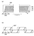
図3(a)は、インクジェットヘッド250の構造例を示す平面透視図であり、図3(b)は、インクジェットヘッド250の他の構造例を示す平面透視図である。図4は、インク室ユニットの立体的構成を示す断面図(図3(a)中、IV−IV線に沿う断面図)である。
FIG. 3A is a plan perspective view showing a structural example of the
記録紙面上に形成されるドットピッチを高密度化するためには、インクジェットヘッド250におけるノズルピッチを高密度化する必要がある。本例のインクジェットヘッド250は、図3(a)に示すように、インク滴の吐出孔であるノズル251と、各ノズル251に対応する圧力室252などからなる複数のインク室ユニット253を千鳥でマトリクス状に(2次元的に)配置させた構造を有し、これにより、ヘッド長手方向(紙搬送方向と直交する主走査方向)に沿って並ぶように投影される実質的なノズル間隔(投影ノズルピッチ)の高密度化を達成している。
In order to increase the dot pitch formed on the recording paper surface, it is necessary to increase the nozzle pitch in the
紙搬送方向と略直交する方向に記録媒体124の全幅に対応する長さにわたり1列以上のノズル列を構成する形態は本例に限定されない。例えば、図3(a)の構成に代えて、図3(b)に示すように、複数のノズル251が2次元に配列された短尺のヘッドブロック(ヘッドチップ)250’を千鳥状に配列して繋ぎ合わせることで記録媒体124の全幅に対応する長さのノズル列を有するラインヘッドを構成してもよい。また、図示は省略するが、短尺のヘッドを一列に並べてラインヘッドを構成してもよい。
The configuration in which one or more nozzle rows are configured over a length corresponding to the entire width of the
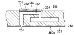
図4に示すように、各ノズル251は、インクジェットヘッド250のインク吐出面250aを構成するノズルプレート260に形成されている。ノズルプレート260は、例えば、Si、SiO2、SiN、石英ガラスのようなシリコン系材料、Al、Fe、Ni、Cuまたはこれらを含む合金のような金属系材料、アルミナ、酸化鉄のような酸化物材料、カーボンブラック、グラファイトのような炭素系材料、ポリイミドのような樹脂系材料で構成されている。
As shown in FIG. 4, each
ノズルプレート260の表面(インク吐出側の面)には、インクに対して撥液性を有する撥水膜262が形成されており、インクの付着防止が図られている。
A
各ノズル251に対応して設けられている圧力室252は、その平面形状が概略正方形となっており、対角線上の両隅部にノズル251と供給口254が設けられている。各圧力室252は供給口254を介して共通流路255と連通されている。共通流路255はインク供給源たるインク供給タンク(不図示)と連通しており、該インク供給タンクから供給されるインクは共通流路255を介して各圧力室252に分配供給される。
The
圧力室252の天面を構成し共通電極と兼用される振動板256には個別電極257を備えた圧電素子258が接合されており、個別電極257に駆動電圧を印加することによって圧電素子258が変形してノズル251からインクが吐出される。インクが吐出されると、共通流路255から供給口254を通って新しいインクが圧力室252に供給される。
A
なお、ノズルの配置構造は図示の例に限定されず、副走査方向に1列のノズル列を有する配置構造など、様々なノズル配置構造を適用できる。 The nozzle arrangement structure is not limited to the illustrated example, and various nozzle arrangement structures such as an arrangement structure having one nozzle row in the sub-scanning direction can be applied.
また、ライン型ヘッドによる印字方式に限定されず、用紙の幅方向(主走査方向)の長さに満たない短尺のヘッドを用紙の幅方向に走査させて当該幅方向の印字を行い、1回の幅方向の印字が終わると用紙を幅方向と直交する方向(副走査方向)に所定量だけ移動させて、次の印字領域の用紙の幅方向の印字を行い、この動作を繰り返して用紙の印字領域の全面にわたって印字を行うシリアル方式を適用してもよい。 Further, the printing method is not limited to a line type head, and printing is performed in the width direction by scanning a short head that is less than the length of the paper in the width direction (main scanning direction) in the width direction of the paper. When printing in the width direction is completed, the paper is moved by a predetermined amount in the direction perpendicular to the width direction (sub-scanning direction), printing is performed in the width direction of the paper in the next print area, and this operation is repeated to A serial method in which printing is performed over the entire printing area may be applied.
<成膜温度の決定>
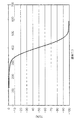
ダイキン製オプツールDSX(20wt%)をTG−DTAの測定部に滴下し、室温下で重量減少が止まるまで待機した。80wt%を占めるパーフルオロヘキサンが揮発し、撥水材料のみがTG−DTAの測定部に残った後、10℃/分の速度で測定部を加熱し、TGデータを得た。TGのデータを図5に示す。図5に示すように、重量減少が10%の温度は300℃、重量減少が90%の温度は470℃であった。
<Determination of deposition temperature>
Daikin OPTOOL DSX (20 wt%) was dropped onto the TG-DTA measurement section and waited at room temperature until the weight loss stopped. Perfluorohexane occupying 80 wt% was volatilized and only the water-repellent material remained in the TG-DTA measurement part, and then the measurement part was heated at a rate of 10 ° C./min to obtain TG data. The TG data is shown in FIG. As shown in FIG. 5, the temperature at which the weight reduction was 10% was 300 ° C., and the temperature at which the weight reduction was 90% was 470 ° C.
(比較例1)
SAMCO社製プラズマCVD装置を用いて、6インチシリコン基板にTEOS(テトラエトキシシラン)を熱気化により供給し、シリコン基板表面にSiO2膜を200nm成膜した。その後、セン特殊光源製低圧水銀灯を用い、大気下で30分間照射し表面を清浄化した。
(Comparative Example 1)
Using a plasma CVD apparatus manufactured by SAMCO, TEOS (tetraethoxysilane) was supplied to a 6-inch silicon substrate by thermal evaporation, and a 200 nm SiO 2 film was formed on the silicon substrate surface. Then, using a low pressure mercury lamp manufactured by Sen Special Light Source, the surface was cleaned by irradiation for 30 minutes in the atmosphere.
その後、上記で形成したSi/SiO2基板を蒸着装置の基板フォルダにセットした。また、オプツールDSX(20wt%)をエッペンドルフ社のピペッタにて50μlを計量し、蒸着加熱部に滴下した。加熱部を250℃に加熱したところ、2時間以上経過しても撥水膜は十分に成膜されていなかった。また、玉状の余分な撥水材料も形成されていなかった。温度が低い条件では、多くの時間を要しても撥水膜は十分に成膜されないことが確認できた。なお、玉状の余分な撥水材料は、光学顕微鏡により確認した。 Thereafter, the Si / SiO 2 substrate formed as described above was set in the substrate folder of the vapor deposition apparatus. Further, 50 μl of OPTOOL DSX (20 wt%) was weighed with an Eppendorf pipettor and dropped onto the vapor deposition heating section. When the heating part was heated to 250 ° C., the water-repellent film was not sufficiently formed even after 2 hours or more had elapsed. Also, no extra ball-like water repellent material was formed. It was confirmed that the water-repellent film was not sufficiently formed under a low temperature condition even if it took a long time. The extra ball-shaped water repellent material was confirmed with an optical microscope.
(比較例2、3)
Si/SiO2基板を比較例1と同様の方法で形成し、蒸着装置にセットした。蒸着源の温度は600℃とした。撥水材料は、比較例1と同等量としたが、突沸を防止するためにアルミナ沸騰石を蒸着加熱部に置き、アルミナ沸騰石を濡らすようにして撥水材料を滴下した。なお、沸騰石を使用しない場合は、突沸が生じ加熱部が汚染された。成膜時間を2分間(600℃に至るまでの時間を含む。以後同様。)(比較例2)としたところ、成膜後の静的接触角は105°であり、撥水膜は十分に被覆されていなかった。成膜時間が3分間(比較例3)では、静的接触角は113°となったが、玉状の余剰の撥水材料が生成された。
(Comparative Examples 2 and 3)
A Si / SiO 2 substrate was formed by the same method as in Comparative Example 1 and set in a vapor deposition apparatus. The temperature of the vapor deposition source was 600 ° C. The amount of water repellent material was the same as in Comparative Example 1, but in order to prevent bumping, the alumina boiling stone was placed in the vapor deposition heating section, and the water repellent material was dropped so as to wet the alumina boiling stone. In addition, when the boiling stone was not used, bumping occurred and the heating part was contaminated. When the film formation time was 2 minutes (including the time to reach 600 ° C., the same applies hereinafter) (Comparative Example 2), the static contact angle after film formation was 105 °, and the water-repellent film was sufficient. It was not coated. When the film formation time was 3 minutes (Comparative Example 3), the static contact angle was 113 °, but a ball-like excess water-repellent material was produced.
また、参考例として比較例2と比較例3の成膜時間の中間の2分30秒の成膜時間で、撥水膜の成膜を5回行なった。しかしながら、静的接触角が110°未満の被覆不十分な状態か、玉状の余剰撥水材料が生成するか、いずれかの状態で成膜は安定していなかった。
Further, as a reference example, the water-repellent film was formed five times with a film formation time of 2
比較例2、3において、インク浸漬試験、ワイプ試験、ノズル詰まり試験を行った。 In Comparative Examples 2 and 3, an ink immersion test, a wipe test, and a nozzle clogging test were performed.
[インク浸漬試験]
アルカリ性のインク中に、60℃の温度で、所定時間、浸漬を行なった。その後の水の静的接触角を測定した。なお、静的接触角が70°未満になるまでの時間が400時間以上かかる撥水膜を実際の使用に耐えられるレベルとし合格とした。
[Ink immersion test]
Immersion was performed in alkaline ink at a temperature of 60 ° C. for a predetermined time. The subsequent static contact angle of water was measured. A water-repellent film that takes 400 hours or more to reach a static contact angle of less than 70 ° was regarded as acceptable for actual use and was accepted.
[ワイプ試験]
東レ製トレシーを治具にセットし、一定圧力となるようにシリコン基板に当接させ、擦り試験を行い、擦り回数1000回おきに水で静的接触角を測定した。水の接触角が70°となる前後で直線を引き、70°となる回数をワイプ寿命とした(例えば、2000回ワイプで80°、3000回ワイプで60°の場合、2500回ワイプを寿命とした)。なお、ワイプ寿命が2000回以上の撥水膜を実際の使用に耐えられるレベルとし合格とした。
[Wipe test]
A Toray-made Toraysee was set on a jig, brought into contact with a silicon substrate so as to have a constant pressure, subjected to a rubbing test, and a static contact angle was measured with water every 1000 times. A straight line is drawn before and after the contact angle of water reaches 70 °, and the number of times it reaches 70 ° is defined as the wipe life (for example, 80 ° for 2000 wipes, 60 ° for 3000 wipes) did). In addition, the water-repellent film having a wipe life of 2000 times or more was regarded as acceptable for actual use and was accepted.
結果を表1に示す。 The results are shown in Table 1.

インク浸漬試験において、比較例2は、24時間で70°まで静的接触角が低下したが、比較例3においては、1000時間浸漬しても静的接触各の低下は見られなかった。また、ワイプ試験においても、比較例3は5200回と良好な結果を得ることができた。 In the ink immersion test, in Comparative Example 2, the static contact angle decreased to 70 ° in 24 hours, but in Comparative Example 3, no decrease in each static contact was observed even after immersion for 1000 hours. Also in the wipe test, Comparative Example 3 was able to obtain a good result of 5200 times.
[ノズル詰まり試験]
次に玉状余剰撥水材料のある膜、ない膜において、ノズル詰まり試験を行った。ノズル詰まり試験は、10回程度ノズル面のワイプを行ない、吐出試験により確認した。玉状余剰撥水材料のない膜は、正常に吐出を行なうことができたが、玉状余剰撥水材料のある膜は、不吐出となり、光学顕微鏡で異物の詰まりが確認された。比較例3においては、インク浸漬試験、ワイプ試験においては良好な結果を得ることができたが、玉状余剰撥水材料が形成されているため、ノズル詰まり試験によりノズル詰まりが発生していた。
[Nozzle clogging test]
Next, a nozzle clogging test was performed on a film with or without a ball-like excess water repellent material. In the nozzle clogging test, the nozzle surface was wiped about 10 times and confirmed by a discharge test. The film without the ball-shaped surplus water-repellent material could be discharged normally, but the film with the ball-shaped surplus water-repellent material was not ejected, and the clogging of foreign matters was confirmed with an optical microscope. In Comparative Example 3, good results could be obtained in the ink immersion test and the wipe test. However, since the excessive water-repellent material in the form of a ball was formed, nozzle clogging occurred in the nozzle clogging test.
また、成膜時間を2分半としたサンプルから、蒸着温度600℃では、同じ成膜時間で成膜を行なっても同一の撥水膜を成膜することができなかった。これは、高温の蒸着温度で成膜すると、単分子膜の形成と、単分子膜上の玉状の余剰撥水材料の形成が同時に進行するからであると考えられる。 Further, from the sample with a film formation time of 2 and a half minutes, the same water-repellent film could not be formed even when film formation was performed at the same film formation time at a deposition temperature of 600 ° C. This is considered to be because when a film is formed at a high deposition temperature, the formation of a monomolecular film and the formation of a ball-like surplus water-repellent material on the monomolecular film proceed simultaneously.
このように、蒸着温度600℃においては、インク浸漬試験およびワイプ試験に耐えられ、かつ、玉状の余剰撥水材料の存在しない撥水膜を成膜することはできなかった。 Thus, at a vapor deposition temperature of 600 ° C., a water-repellent film that can withstand the ink immersion test and the wipe test and does not have a ball-like surplus water-repellent material could not be formed.
(比較例4)
Si/SiO2基板を比較例1と同様の方法で形成し、蒸着装置にセットした。蒸着温度は500℃とし、突沸は見られなかったため、加熱部の汚染はなく、沸騰石は用いずに成膜した。
(Comparative Example 4)
A Si / SiO 2 substrate was formed by the same method as in Comparative Example 1 and set in a vapor deposition apparatus. Since the vapor deposition temperature was 500 ° C. and bumping was not observed, there was no contamination of the heating part, and the film was formed without using boiling stones.
しかしながら、比較例2、3と同様に、成膜時間3分では110°以上の静的接触角を得ることができず、成膜時間4分では玉状の余剰撥水材料が生成していた。また、成膜時間を3分30秒とした場合も、毎回同じ膜を形成することができなかった。
However, as in Comparative Examples 2 and 3, a static contact angle of 110 ° or more could not be obtained at the film formation time of 3 minutes, and a ball-shaped surplus water-repellent material was generated at the film formation time of 4 minutes. . Further, even when the film formation time was 3
(実施例1、比較例5、6)
Si/SiO2基板を比較例1と同様の方法で形成し、蒸着装置にセットした。蒸着温度は450℃とし、成膜時間を3分(比較例6)、4分(実施例1)、5分(比較例7)とし、成膜を行なった。結果を表2に示す。
(Example 1, Comparative Examples 5 and 6)
A Si / SiO 2 substrate was formed by the same method as in Comparative Example 1 and set in a vapor deposition apparatus. The deposition temperature was 450 ° C., and the film formation time was 3 minutes (Comparative Example 6), 4 minutes (Example 1), and 5 minutes (Comparative Example 7). The results are shown in Table 2.
成膜時間の短い比較例5においては、静的接触角が105°であり、十分な撥水性を有する膜を成膜することができなかった。また、成膜時間の長い比較例6においては、玉状余剰撥水材料が付着しており、ノズル詰まりが発生すると考えられる。成膜時間を4分とすることで、玉状余剰撥水材料が見られず、また、静的接触角が110°以上となる良質な膜を安定して得ることができた。 In Comparative Example 5 having a short film formation time, the static contact angle was 105 °, and a film having sufficient water repellency could not be formed. Further, in Comparative Example 6 having a long film formation time, it is considered that the ball-like surplus water-repellent material is adhered and nozzle clogging occurs. By setting the film formation time to 4 minutes, no ball-like surplus water-repellent material was observed, and a high-quality film having a static contact angle of 110 ° or more could be stably obtained.
(実施例2〜4、比較例7、8)
Si/SiO2基板を比較例1と同様の方法で形成し、蒸着装置にセットした。蒸着温度は400℃とし、成膜時間を5分(比較例7)、10分(実施例2)、20分(実施例3)、30分(実施例4)、40分(比較例8)とし、成膜を行なった。結果を表3に示す。
(Examples 2 to 4, Comparative Examples 7 and 8)
A Si / SiO 2 substrate was formed by the same method as in Comparative Example 1 and set in a vapor deposition apparatus. The deposition temperature is 400 ° C., and the film formation time is 5 minutes (Comparative Example 7), 10 minutes (Example 2), 20 minutes (Example 3), 30 minutes (Example 4), and 40 minutes (Comparative Example 8). The film was formed. The results are shown in Table 3.
蒸着温度を400℃とした場合、成膜時間を10分〜30分とした実施例2〜4においては、玉状余剰撥水材料がなく、また、静的接触角が110°以上の良質な膜が得られた。 When the deposition temperature is 400 ° C., in Examples 2 to 4 in which the film formation time is 10 minutes to 30 minutes, there is no excessive ball-shaped water repellent material, and the static contact angle is 110 ° or more. A membrane was obtained.
特に、実施例4においては、インク浸漬試験にもワイプ試験にも優れた膜を得ることができた。インク浸漬試験、ワイプ試験については、比較例3において良好な結果が得られているが、玉状余剰撥水材料があるため、ノズル詰まりが発生することが考えられる。実施例4においては、インク浸漬試験、ワイプ試験に関して同様の結果が得られており、玉状余剰物質がなく、かつ、単分子膜が密に成膜された撥水膜が形成されている。逆に、比較例6においては、玉状余剰撥水材料が存在しても、インク浸漬耐性、ワイプ耐性も良好ではなく、単分子膜で完全に被覆されないうちから、玉状の余剰撥水材料が付着しているといえる。 In particular, in Example 4, a film excellent in both the ink immersion test and the wipe test could be obtained. As for the ink immersion test and the wipe test, good results were obtained in Comparative Example 3, but it is considered that nozzle clogging occurs due to the presence of the ball-shaped excessive water repellent material. In Example 4, similar results were obtained with respect to the ink immersion test and the wipe test, and a water repellent film in which the monomolecular film was densely formed without any excessive ball-shaped substance was formed. On the contrary, in Comparative Example 6, even if a ball-like surplus water-repellent material is present, ink immersion resistance and wipe resistance are not good, and the ball-like surplus water-repellent material is not completely covered with a monomolecular film. It can be said that is attached.
以上より、成膜温度が低い場合は、十分な撥水性を有する撥水膜が形成されず、成膜温度が高い場合は、十分な撥水性を有する撥水膜が形成されるが、玉状余剰撥水材料が形成されやすいため、ノズル詰まりが発生しやすいことが確認できる。したがって、撥水膜の蒸着温度を所定の範囲内で行なうことで、良好な撥水膜を形成することができる。 From the above, when the film formation temperature is low, a water-repellent film having sufficient water repellency is not formed, and when the film formation temperature is high, a water-repellent film having sufficient water repellency is formed. It can be confirmed that nozzle clogging is likely to occur because an excessive water repellent material is easily formed. Therefore, a good water-repellent film can be formed by performing the water-repellent film deposition temperature within a predetermined range.
また、成膜時間が短い場合は、十分な撥水性を有する撥水膜が形成されず、成膜時間が長い場合は、形成された撥水膜の上に、玉状余剰撥水材料が形成され、ノズル詰まりの原因となるため、玉状余剰撥水材料が形成される前に撥水膜の成膜を止めることが好ましい。また、その成膜時間の中で、長い時間行なうことで、より密度の高い単分子膜を成膜することができる。 In addition, when the film formation time is short, a water-repellent film having sufficient water repellency is not formed, and when the film formation time is long, a ball-shaped surplus water-repellent material is formed on the formed water-repellent film. In order to cause clogging of the nozzle, it is preferable to stop the formation of the water-repellent film before the ball-shaped surplus water-repellent material is formed. Further, a monomolecular film having a higher density can be formed by performing a long time in the film formation time.
[滑落性試験]
滴サイズ10μlの純水を撥水膜上に滴下し、ステージを傾けて滑落を開始する角度を測定した。実施例、比較例の温度条件で複数の膜を作製し、玉状余剰撥水材料の有無で比較を行った。
[Sliding test]
Pure water having a droplet size of 10 μl was dropped on the water-repellent film, and the angle at which the slide was started by tilting the stage was measured. A plurality of films were produced under the temperature conditions of the example and the comparative example, and the comparison was made with or without the ball-shaped excess water repellent material.
静的接触角が110°未満の撥水膜では、ステージを80°まで傾けても水滴は滑落しなかった。撥水膜の被覆が不十分で、基板の親水基に水がトラップされるからであると推定される。 In the case of a water-repellent film having a static contact angle of less than 110 °, water drops did not slide down even when the stage was tilted up to 80 °. This is presumably because the water-repellent film is not sufficiently coated and water is trapped in the hydrophilic group of the substrate.
玉状余剰撥水材料がある膜は、いずれも30°以上の滑落角となり、特に、比較例3の膜では、水滴は80°まで傾けても滑落しなかった。 All of the films having the ball-like surplus water-repellent material had a sliding angle of 30 ° or more. In particular, in the film of Comparative Example 3, the water droplets did not slide down even when tilted to 80 °.
玉状余剰撥水材料が形成されない条件で撥水膜を成膜することにより、液滴の滑落性(動的撥水性)に対しても効果を有することが確認された。 It was confirmed that the formation of the water-repellent film under the condition that the ball-like surplus water-repellent material is not formed has an effect on the sliding property (dynamic water repellency) of the droplet.
図6に、高温、中温、低温での成膜温度に対して、横軸に成膜時間をとった場合の生成される膜の状態を示す。なお、図6は、各温度における成膜時間に対する膜の状態を示す概略図であり、成膜時間は、温度により異なっている。 FIG. 6 shows the state of the film produced when the film formation time is plotted on the horizontal axis with respect to the film formation temperature at high temperature, medium temperature, and low temperature. FIG. 6 is a schematic diagram showing the state of the film with respect to the film formation time at each temperature, and the film formation time varies depending on the temperature.
図6に示すように、温度が高温(600℃、500℃)の場合は、単分子膜が密に形成されず、ワイプ耐性が十分に得られない状態で、玉状余剰撥水材料が形成される。さらに、成膜を行うことで、ワイプ耐性は高いが、玉状余剰撥水材料が形成された膜が形成される。したがって、温度が高温である場合は、玉状余剰撥水材料が形成されず単分子膜が密に形成された膜を成膜することはできない。 As shown in FIG. 6, when the temperature is high (600 ° C., 500 ° C.), the monomolecular film is not densely formed and the ball-shaped surplus water-repellent material is formed in a state where sufficient wipe resistance is not obtained. Is done. Furthermore, by performing the film formation, a film on which a ball-shaped surplus water-repellent material is formed is formed although the wipe resistance is high. Therefore, when the temperature is high, a ball-like surplus water repellent material is not formed, and a film in which a monomolecular film is densely formed cannot be formed.
温度が中温(450℃)の場合については、成膜時間が短い場合は、撥水膜の密度の低い膜が生成し、成膜時間を長くすることで、玉状の余剰撥水材料が形成されず、ワイプ耐久性の良好な膜を成膜することができる。しかし、そのまま成膜を続けると撥水膜が完全に被覆する前に玉状の余剰撥水材料が形成される。 When the temperature is medium temperature (450 ° C.), when the film formation time is short, a film having a low density of the water repellent film is formed, and by increasing the film formation time, a ball-shaped excess water repellent material is formed. However, a film having good wipe durability can be formed. However, if the film formation is continued as it is, a ball-like surplus water-repellent material is formed before the water-repellent film is completely covered.
温度を低温(400℃)とした場合は、時間により単分子膜を密に成膜することができ、玉状余剰撥水材料が形成される前に撥水膜で完全に被覆することができる。しかしながら、そのまま成膜を続けることで、玉状の余剰撥水材料が形成されるため、所定の時間で成膜を止めることで、ワイプ耐久性、耐薬品性が高く、玉状の撥水材料の形成されていない撥水膜を製造することができる。 When the temperature is low (400 ° C.), the monomolecular film can be densely formed over time and can be completely covered with the water repellent film before the ball-shaped surplus water repellent material is formed. . However, by continuing the film formation as it is, a ball-shaped excess water-repellent material is formed. By stopping the film formation within a predetermined time, the wiped durability and chemical resistance are high, and the ball-shaped water-repellent material It is possible to produce a water-repellent film in which no is formed.
以上のように、成膜温度を突沸の生じない温度未満、好ましくは、10℃/分の速度で昇温した場合の重量減少が10%以上90%以内の温度を成膜温度とすることで、撥水性、耐薬品性、耐ワイプ性の良好な撥水膜を成膜することができる。ただし、成膜時間が長くなると撥水膜表面に玉状の余剰撥水材料が形成され、この余剰撥水材料がワイプにより剥離し、ノズル詰まりの原因となるため、余剰撥水材料が形成される前に成膜を停めることにより、良好な物性で、ノズル詰まりは発生しにくい成膜条件を決定することができる。 As described above, the film formation temperature is set to a temperature lower than the temperature at which bumping does not occur, preferably a temperature at which weight loss when heated at a rate of 10 ° C./min is 10% or more and 90% or less. A water-repellent film having good water repellency, chemical resistance, and wipe resistance can be formed. However, if the film formation time is lengthened, a ball-shaped excess water repellent material is formed on the surface of the water repellent film, and this excess water repellent material is peeled off by wiping and causes nozzle clogging. By stopping the film formation before the film formation, it is possible to determine the film formation conditions with good physical properties and in which nozzle clogging is unlikely to occur.
このようにして形成された撥水膜は、例えば、実施例2、3のような比較的インク浸漬耐性の低い撥水膜、ワイプ耐性の低い撥水膜については、成膜時間を短くすることができるので、生産効率が高く、使い捨ての材料として使用することができる。また、実施例4のようなインク浸漬耐性、ワイプ耐性の高い撥水膜については、耐久性のある材料として使用することができる。 For the water-repellent film formed in this way, for example, the water-repellent film having a relatively low ink immersion resistance and the water-repellent film having a low wipe resistance as in Examples 2 and 3, shorten the film formation time. Therefore, production efficiency is high and it can be used as a disposable material. Further, the water-repellent film having high ink immersion resistance and high wipe resistance as in Example 4 can be used as a durable material.
10…基板、30…撥水膜、31…シランカップリング剤、100…インクジェット記録装置、112…給紙部、114…処理液付与部、116…描画部、118…乾燥部、120…定着部、122…排出部、124…記録媒体、154…処理液ドラム、156…処理液塗布装置、170…描画ドラム、172M、172K、172C、172Y…インクジェットヘッド、176…乾燥ドラム、180…温風噴出しノズル、182…IRヒータ、184…定着ドラム、186…ハロゲンヒータ、188…定着ローラ、192…排出トレイ、196…搬送ベルト
DESCRIPTION OF
Claims (8)
前記有機膜被覆工程における成膜条件を、前記基板と同じ材料を用いて、予め決定する成膜条件決定工程と、を有し、
前記成膜条件決定工程は、前記シランカップリング剤が、蒸発する温度以上突沸が起こらない温度以下に決定する温度決定工程と、前記温度決定工程で決定した温度において、有機膜を被覆し、光学顕微鏡観察により玉状の余剰撥水材料が形成される時間を測定し、前記時間より短い時間を成膜時間と決定する成膜時間決定工程と、からなる撥水膜の製造方法。 An organic film coating step of coating an organic film with a silane coupling agent on the substrate by a vapor deposition method;
Using the same material as the substrate, the film formation conditions in the organic film coating step are determined in advance, and
The film forming condition determining step includes: a temperature determining step for determining a temperature at which the silane coupling agent evaporates to a temperature at which bumping does not occur; a temperature determined at the temperature determining step; A method for producing a water repellent film, comprising: a film formation time determining step of measuring a time for forming a ball-shaped surplus water repellent material by microscopic observation, and determining a time shorter than the time as a film formation time.
Priority Applications (2)
| Application Number | Priority Date | Filing Date | Title |
|---|---|---|---|
| JP2012016924A JP5497810B2 (en) | 2012-01-30 | 2012-01-30 | Method for producing water repellent film |
| US13/753,379 US9012670B2 (en) | 2012-01-30 | 2013-01-29 | Method of manufacturing water repellent film and thereby manufactured water repellent film |
Applications Claiming Priority (1)
| Application Number | Priority Date | Filing Date | Title |
|---|---|---|---|
| JP2012016924A JP5497810B2 (en) | 2012-01-30 | 2012-01-30 | Method for producing water repellent film |
Publications (2)
| Publication Number | Publication Date |
|---|---|
| JP2013155408A true JP2013155408A (en) | 2013-08-15 |
| JP5497810B2 JP5497810B2 (en) | 2014-05-21 |
Family
ID=48870785
Family Applications (1)
| Application Number | Title | Priority Date | Filing Date |
|---|---|---|---|
| JP2012016924A Expired - Fee Related JP5497810B2 (en) | 2012-01-30 | 2012-01-30 | Method for producing water repellent film |
Country Status (2)
| Country | Link |
|---|---|
| US (1) | US9012670B2 (en) |
| JP (1) | JP5497810B2 (en) |
Cited By (4)
| Publication number | Priority date | Publication date | Assignee | Title |
|---|---|---|---|---|
| JP2019051637A (en) * | 2017-09-14 | 2019-04-04 | 東芝テック株式会社 | Ink jet head and ink jet printer |
| JP2019051639A (en) * | 2017-09-14 | 2019-04-04 | 東芝テック株式会社 | Ink jet head and ink jet printer |
| JP2019077103A (en) * | 2017-10-25 | 2019-05-23 | 東芝テック株式会社 | Inkjet head and inkjet printer |
| JP7297959B2 (en) | 2017-10-25 | 2023-06-26 | 東芝テック株式会社 | Inkjet head and inkjet printer |
Citations (6)
| Publication number | Priority date | Publication date | Assignee | Title |
|---|---|---|---|---|
| JP2000328230A (en) * | 1999-05-20 | 2000-11-28 | Toray Ind Inc | Method for deposition of organic film |
| JP2003014904A (en) * | 2001-04-27 | 2003-01-15 | Hoya Corp | Method for manufacturing optical member having water- repellent thin film |
| JP2006348376A (en) * | 2005-06-20 | 2006-12-28 | Seiko Epson Corp | Vacuum deposition method, and vacuum deposition system |
| JP2007332433A (en) * | 2006-06-16 | 2007-12-27 | Seiko Epson Corp | Vacuum vapor-deposition apparatus |
| JP2009220396A (en) * | 2008-03-17 | 2009-10-01 | Ricoh Co Ltd | Nozzle plate, liquid droplet ejection head, liquid cartridge and inkjet recorder |
| JP2010076422A (en) * | 2008-08-27 | 2010-04-08 | Ricoh Co Ltd | Liquid ejection head, image forming apparatus, and method of manufacturing liquid ejection head |
Family Cites Families (4)
| Publication number | Priority date | Publication date | Assignee | Title |
|---|---|---|---|---|
| US6331329B1 (en) * | 1999-05-17 | 2001-12-18 | University Of Massachusetts | Surface modification using hydridosilanes to prepare monolayers |
| JP4496809B2 (en) | 2004-03-16 | 2010-07-07 | セイコーエプソン株式会社 | Droplet discharge head manufacturing method, droplet discharge head, and droplet discharge apparatus |
| US6991826B2 (en) | 2004-04-20 | 2006-01-31 | 3M Innovative Properties Company | Antisoiling coatings for antireflective substrates |
| JP2006291266A (en) | 2005-04-08 | 2006-10-26 | Daikin Ind Ltd | Method of vapor-phase surface treatment with fluorine compound |
-
2012
- 2012-01-30 JP JP2012016924A patent/JP5497810B2/en not_active Expired - Fee Related
-
2013
- 2013-01-29 US US13/753,379 patent/US9012670B2/en not_active Expired - Fee Related
Patent Citations (6)
| Publication number | Priority date | Publication date | Assignee | Title |
|---|---|---|---|---|
| JP2000328230A (en) * | 1999-05-20 | 2000-11-28 | Toray Ind Inc | Method for deposition of organic film |
| JP2003014904A (en) * | 2001-04-27 | 2003-01-15 | Hoya Corp | Method for manufacturing optical member having water- repellent thin film |
| JP2006348376A (en) * | 2005-06-20 | 2006-12-28 | Seiko Epson Corp | Vacuum deposition method, and vacuum deposition system |
| JP2007332433A (en) * | 2006-06-16 | 2007-12-27 | Seiko Epson Corp | Vacuum vapor-deposition apparatus |
| JP2009220396A (en) * | 2008-03-17 | 2009-10-01 | Ricoh Co Ltd | Nozzle plate, liquid droplet ejection head, liquid cartridge and inkjet recorder |
| JP2010076422A (en) * | 2008-08-27 | 2010-04-08 | Ricoh Co Ltd | Liquid ejection head, image forming apparatus, and method of manufacturing liquid ejection head |
Cited By (6)
| Publication number | Priority date | Publication date | Assignee | Title |
|---|---|---|---|---|
| JP2019051637A (en) * | 2017-09-14 | 2019-04-04 | 東芝テック株式会社 | Ink jet head and ink jet printer |
| JP2019051639A (en) * | 2017-09-14 | 2019-04-04 | 東芝テック株式会社 | Ink jet head and ink jet printer |
| JP6991806B2 (en) | 2017-09-14 | 2022-01-13 | 東芝テック株式会社 | Inkjet heads and inkjet printers |
| JP6995540B2 (en) | 2017-09-14 | 2022-02-04 | 東芝テック株式会社 | Inkjet heads and inkjet printers |
| JP2019077103A (en) * | 2017-10-25 | 2019-05-23 | 東芝テック株式会社 | Inkjet head and inkjet printer |
| JP7297959B2 (en) | 2017-10-25 | 2023-06-26 | 東芝テック株式会社 | Inkjet head and inkjet printer |
Also Published As
| Publication number | Publication date |
|---|---|
| US9012670B2 (en) | 2015-04-21 |
| JP5497810B2 (en) | 2014-05-21 |
| US20130197255A1 (en) | 2013-08-01 |
Similar Documents
| Publication | Publication Date | Title |
|---|---|---|
| US8596760B2 (en) | Droplet ejection head and method of manufacturing droplet ejection head | |
| JP5818340B2 (en) | Method for forming water repellent film | |
| JP2013052546A (en) | Structure having liquid-repellent surface, nozzle plate of inkjet head, and method for cleaning structure and nozzle plate | |
| JP5666417B2 (en) | Method for manufacturing droplet discharge head | |
| JP5497810B2 (en) | Method for producing water repellent film | |
| US20110074871A1 (en) | Method of Forming Organic Film, and Organic Film, Nozzle Plate and Inkjet Recording Apparatus | |
| JP5752816B2 (en) | Water repellent film manufacturing method, nozzle plate, ink jet head, and ink jet recording apparatus | |
| JP2013188874A (en) | Method for manufacturing liquid ejection head | |
| WO2015033911A1 (en) | Water-repellent film, film formation method, nozzle plate, ink-jet head, and ink-jet recording device | |
| JP5764312B2 (en) | Ink jet recording apparatus and nozzle plate cleaning method | |
| JP6017319B2 (en) | Method for producing water repellent film | |
| JP2011194668A (en) | Method for forming water repellent film, nozzle plate and ink jet head equipped with the same, and electronic device | |
| JP6112990B2 (en) | Liquid discharge head maintenance method, liquid discharge head | |
| US8475885B2 (en) | Method of forming organic film, and organic film, nozzle plate, inkjet head and electronic device | |
| US8367158B2 (en) | Liquid-repellent film forming method, inkjet head and inkjet recording apparatus | |
| JP2012000784A (en) | Liquid ejection head and liquid ejector | |
| JP2012213873A (en) | Method of forming water-repellent film, nozzle plate, ink jet head and ink jet recording device | |
| US8628829B2 (en) | Method of forming organic film, and nozzle plate, inkjet head and electronic device | |
| JP2012213872A (en) | Method of forming water-repellent film, nozzle plate, ink jet head and ink jet recording device | |
| JP5550143B2 (en) | Method for producing hydrophilic thin film | |
| JP5903359B2 (en) | Method for producing water repellent film and method for producing nozzle plate | |
| JP5657328B2 (en) | Inkjet head manufacturing method and inkjet head | |
| JP2012218289A (en) | Method for manufacturing nozzle plate, nozzle plate, and droplet discharge head | |
| JP2003127384A (en) | Method for manufacturing ink jet head and ink jet printer having the head | |
| JP2012056122A (en) | Manufacturing method of nozzle plate, nozzle plate, ink jet head and electronic device |
Legal Events
| Date | Code | Title | Description |
|---|---|---|---|
| A621 | Written request for application examination |
Free format text: JAPANESE INTERMEDIATE CODE: A621 Effective date: 20130826 |
|
| A977 | Report on retrieval |
Free format text: JAPANESE INTERMEDIATE CODE: A971007 Effective date: 20131209 |
|
| A131 | Notification of reasons for refusal |
Free format text: JAPANESE INTERMEDIATE CODE: A131 Effective date: 20131213 |
|
| A521 | Request for written amendment filed |
Free format text: JAPANESE INTERMEDIATE CODE: A523 Effective date: 20140129 |
|
| TRDD | Decision of grant or rejection written | ||
| A01 | Written decision to grant a patent or to grant a registration (utility model) |
Free format text: JAPANESE INTERMEDIATE CODE: A01 Effective date: 20140304 |
|
| A61 | First payment of annual fees (during grant procedure) |
Free format text: JAPANESE INTERMEDIATE CODE: A61 Effective date: 20140306 |
|
| R150 | Certificate of patent or registration of utility model |
Ref document number: 5497810 Country of ref document: JP Free format text: JAPANESE INTERMEDIATE CODE: R150 |
|
| R250 | Receipt of annual fees |
Free format text: JAPANESE INTERMEDIATE CODE: R250 |
|
| R250 | Receipt of annual fees |
Free format text: JAPANESE INTERMEDIATE CODE: R250 |
|
| R250 | Receipt of annual fees |
Free format text: JAPANESE INTERMEDIATE CODE: R250 |
|
| R250 | Receipt of annual fees |
Free format text: JAPANESE INTERMEDIATE CODE: R250 |
|
| R250 | Receipt of annual fees |
Free format text: JAPANESE INTERMEDIATE CODE: R250 |
|
| LAPS | Cancellation because of no payment of annual fees |