JP2013115366A - Support device and support method of long body - Google Patents
Support device and support method of long body Download PDFInfo
- Publication number
- JP2013115366A JP2013115366A JP2011262601A JP2011262601A JP2013115366A JP 2013115366 A JP2013115366 A JP 2013115366A JP 2011262601 A JP2011262601 A JP 2011262601A JP 2011262601 A JP2011262601 A JP 2011262601A JP 2013115366 A JP2013115366 A JP 2013115366A
- Authority
- JP
- Japan
- Prior art keywords
- core member
- shaft core
- data carrier
- support
- data
- Prior art date
- Legal status (The legal status is an assumption and is not a legal conclusion. Google has not performed a legal analysis and makes no representation as to the accuracy of the status listed.)
- Granted
Links
- 238000000034 method Methods 0.000 title claims abstract description 10
- 238000004891 communication Methods 0.000 claims description 42
- 230000008569 process Effects 0.000 claims description 2
- 239000000853 adhesive Substances 0.000 description 36
- 230000001070 adhesive effect Effects 0.000 description 36
- 235000012431 wafers Nutrition 0.000 description 16
- 239000004744 fabric Substances 0.000 description 15
- 239000000463 material Substances 0.000 description 7
- 230000005540 biological transmission Effects 0.000 description 6
- 238000003780 insertion Methods 0.000 description 5
- 230000037431 insertion Effects 0.000 description 5
- 239000011347 resin Substances 0.000 description 5
- 229920005989 resin Polymers 0.000 description 5
- 239000004065 semiconductor Substances 0.000 description 5
- 239000000969 carrier Substances 0.000 description 4
- 239000010410 layer Substances 0.000 description 4
- 230000033001 locomotion Effects 0.000 description 4
- 239000012790 adhesive layer Substances 0.000 description 3
- 230000001681 protective effect Effects 0.000 description 3
- 229910000831 Steel Inorganic materials 0.000 description 2
- 230000006870 function Effects 0.000 description 2
- 230000003287 optical effect Effects 0.000 description 2
- 239000002994 raw material Substances 0.000 description 2
- 239000005060 rubber Substances 0.000 description 2
- 239000010959 steel Substances 0.000 description 2
- XUIMIQQOPSSXEZ-UHFFFAOYSA-N Silicon Chemical compound [Si] XUIMIQQOPSSXEZ-UHFFFAOYSA-N 0.000 description 1
- 230000008859 change Effects 0.000 description 1
- 150000001875 compounds Chemical class 0.000 description 1
- 239000004020 conductor Substances 0.000 description 1
- 230000006837 decompression Effects 0.000 description 1
- 238000001514 detection method Methods 0.000 description 1
- 230000005611 electricity Effects 0.000 description 1
- 230000004907 flux Effects 0.000 description 1
- 239000011521 glass Substances 0.000 description 1
- 230000002452 interceptive effect Effects 0.000 description 1
- 239000000696 magnetic material Substances 0.000 description 1
- 238000012986 modification Methods 0.000 description 1
- 230000004048 modification Effects 0.000 description 1
- 239000000123 paper Substances 0.000 description 1
- 230000002093 peripheral effect Effects 0.000 description 1
- 238000000275 quality assurance Methods 0.000 description 1
- 229910052710 silicon Inorganic materials 0.000 description 1
- 239000010703 silicon Substances 0.000 description 1
- 239000007921 spray Substances 0.000 description 1
- 230000003068 static effect Effects 0.000 description 1
- 239000000758 substrate Substances 0.000 description 1
- 239000002023 wood Substances 0.000 description 1
Images
Abstract
Description
本発明は、長尺体の支持装置および支持方法に関する。 The present invention relates to a long body support device and a support method.
従来、帯状の接着シートを繰り出して半導体ウェハ(以下「ウェハ」と称す場合がある)に貼付する貼付装置において、接着シートが巻回された軸芯部材にデータキャリアを設け、当該データキャリアに書き込まれたデータを読み取って、貼付条件を適切に設定する構成が知られている(例えば、特許文献1参照)。
この特許文献1に記載の構成では、軸芯部材の内面にデータキャリアを設けるとともに、軸芯部材が装着される巻き出し軸にテープデータ読み書き装置を設けている。
2. Description of the Related Art Conventionally, in a pasting apparatus that feeds a strip-shaped adhesive sheet and pastes it on a semiconductor wafer (hereinafter sometimes referred to as “wafer”), a data carrier is provided on a shaft core member around which the adhesive sheet is wound, and the data carrier is written. A configuration is known in which the data is read to appropriately set the pasting conditions (see, for example, Patent Document 1).
In the configuration described in Patent Document 1, a data carrier is provided on the inner surface of the shaft member, and a tape data read / write device is provided on the unwinding shaft on which the shaft member is mounted.
しかしながら、特許文献1に記載の構成では、データキャリアが巻き出し軸周りに位置ずれを起こしてしまうと、データの読み取りや書き取り(データの通信)を行うことができなくなるため、データキャリアとテープデータ読み書き装置との位置合わせを正確に行わなければならず、軸芯部材の装着作業が煩わしいという問題がある。 However, in the configuration described in Patent Document 1, if the data carrier is displaced around the unwinding axis, data cannot be read or written (data communication). There is a problem that the positioning with the reading / writing device must be performed accurately, and the mounting work of the shaft core member is troublesome.
本発明の目的は、長尺体が巻回されかつデータキャリアが設けられた軸芯部材を支持軸で支持する際に、データキャリアに対するデータの通信を適切に行うための正確な位置合わせが不要な長尺体の支持装置および支持方法を提供することにある。 The object of the present invention is to eliminate the need for accurate alignment for appropriately communicating data to the data carrier when the shaft member on which the long body is wound and the data carrier is supported by the support shaft. An object of the present invention is to provide a support device and a support method for a long body.
前記目的を達成するために、本発明の長尺体の支持装置は、中空筒状の軸芯部材に巻回された長尺体を繰出可能に支持、または、中空筒状の軸芯部材に長尺体を巻取可能に支持する長尺体の支持装置において、基端部と先端部とを有し、前記軸芯部材における中空部の一端側を当該先端部側から挿入することで当該軸芯部材を支持する支持軸と、前記支持軸を前記基端部側から支えるフレームと、前記支持軸の先端部に着脱可能に設けられ、当該先端部に取り付けることにより前記軸芯部材の位置決めが可能なガイド手段とを備え、前記軸芯部材には、中空部の他端側であって当該軸芯部材の軸線に交差する面内に、所定のデータの記憶および送信の少なくとも一方が可能なデータキャリアが設けられ、前記ガイド手段には、前記支持軸の先端部に固定されたときに、前記データキャリアと対向して配置され、当該データキャリアと通信可能な通信部が設けられている、という構成を採用している。 In order to achieve the above object, the long body support device of the present invention supports the long body wound around the hollow cylindrical shaft core member so that the long body can be fed, or the hollow cylindrical shaft core member In a long body support device that supports a long body in a rollable manner, the long body has a proximal end portion and a distal end portion, and is inserted by inserting one end side of the hollow portion of the shaft core member from the distal end portion side. A support shaft for supporting the shaft core member, a frame for supporting the support shaft from the base end side, and a detachably provided at the distal end portion of the support shaft, and positioning the shaft core member by attaching to the distal end portion The shaft core member is capable of at least one of storing and transmitting predetermined data in a plane on the other end side of the hollow portion and intersecting the axis of the shaft core member. A data carrier is provided, and the guide means includes a tip of the support shaft. When secured to section, the disposed data carrier and opposite to, available communication section with the data carrier adopts the configuration that is provided.
この際、前記ガイド手段は、前記データキャリアに記憶させるデータ、および、前記データキャリアから前記通信部が受信または読み取ったデータを無線通信可能な無線通信手段を備えていることが好ましい。 In this case, it is preferable that the guide unit includes a wireless communication unit capable of wirelessly communicating data stored in the data carrier and data received or read by the communication unit from the data carrier.
一方、本発明の長尺体の支持方法は、中空筒状の軸芯部材に巻回された長尺体を繰出可能に支持、または、中空筒状の軸芯部材に長尺体を巻取可能に支持する長尺体の支持方法において、前記軸芯部材における中空部の他端側であって当該軸芯部材の軸線に交差する面内に、所定のデータの記憶および送信の少なくとも一方が可能なデータキャリアが設けられた軸芯部材を用意する工程と、前記軸芯部材における中空部の一端側を支持軸の先端部側から挿入して当該軸芯部材を支持する工程と、前記支持軸の先端部に前記軸芯部材の位置決めが可能なガイド手段を取り付けることで、当該ガイド手段に設けられた通信部と前記データキャリアとを対向させて支持する工程と、前記通信部とデータキャリアとで通信を行う工程とを有する、という構成を採用している。 On the other hand, the long body support method of the present invention supports the long body wound around the hollow cylindrical shaft core member so that the long body can be fed, or winds the long body around the hollow cylindrical shaft core member. In the method of supporting an elongated body to be supported, at least one of storage and transmission of predetermined data is performed on the other end side of the hollow portion of the shaft core member and in a plane intersecting the axis of the shaft core member. A step of preparing a shaft member provided with a possible data carrier, a step of inserting one end side of the hollow portion of the shaft core member from the tip end side of the support shaft, and supporting the shaft member, and the support Attaching the guide means capable of positioning the shaft core member to the tip portion of the shaft, and supporting the communication section provided on the guide means and the data carrier opposite to each other; and the communication section and the data carrier And having a process of communicating with It has adopted the configuration.
以上のような本発明によれば、軸芯部材が支持軸に挿入され、先端部にガイド手段が固定されさえすれば、データキャリアと、例えばアンテナなどの通信部とが確実に対向することとなり、従来のようにデータキャリアとループアンテナとの通信を適切に行うための正確な位置合わせが不要となる。 According to the present invention as described above, as long as the shaft core member is inserted into the support shaft and the guide means is fixed to the tip portion, the data carrier and the communication unit such as an antenna are reliably opposed to each other. As in the prior art, accurate alignment for appropriately performing communication between the data carrier and the loop antenna becomes unnecessary.
この際、ガイド手段が、無線通信手段を備えていれば、データキャリアに記憶されたデータを読み取ったり、データキャリアにデータを書き込んだりすることのできるリーダライタなどの装置を通信部に配線する必要がなくなり、配線の手間が省けるとともに、当該装置を無線通信手段と通信可能な範囲の任意の場所に設置できる。 At this time, if the guide means includes wireless communication means, it is necessary to wire a communication unit such as a reader / writer that can read data stored in the data carrier and write data to the data carrier. This eliminates the need for wiring, and allows the device to be installed in any location within the range where it can communicate with the wireless communication means.
以下、本発明の一実施形態を図面に基づいて説明する。なお、各図においては、本発明の内容を理解しやすくするために各構成の形状や配置状態を誇張して示している。また、本実施形態において基準となる図を挙げることなく、例えば、上、下、左、右、または、手前、奥といった方向を示した場合は、全て図1を基準としている。
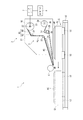
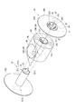
図1において、貼付装置1は、ウェハWFに接着シートASを貼付するものである。ここで、接着シートASは、基材シートBSの一方の面に接着剤層ADが積層されるとともに、当該接着剤層ADを介して剥離シートRLに仮着された長尺体としての原反RSとし、中空円筒状の軸芯部材23の外周に巻回されて予め準備されている。なお、軸芯部材23の両端には、それぞれデータキャリア29が設けられている。
各データキャリア29は、軸芯部材23の端面231における開口の一部を覆うとともに、当該軸芯部材23の軸線CFに直交する面内に設けられている。これらデータキャリア29は、端面231の外周縁の一部に沿う被着体類似縁291と、逃げ縁292とに囲まれた平面視でD字状に形成されている。
データキャリア29は、電磁波を通信媒体としてデータを読み取って記憶したり、データを送信したりすることができるものである。このようなデータキャリア29としては、例えば、ICチップと、このICチップに接続された送受信用の導電性コイルとから構成されるいわゆるRFメモリやRFIDタグ等を用いることができる。
Hereinafter, an embodiment of the present invention will be described with reference to the drawings. In each of the drawings, the shape and arrangement of each component are exaggerated for easy understanding of the contents of the present invention. Further, for example, when directions such as up, down, left, right, front, and back are shown without giving a reference figure in the present embodiment, all are based on FIG.
In FIG. 1, a sticking device 1 sticks an adhesive sheet AS to a wafer WF. Here, the adhesive sheet AS has an adhesive layer AD laminated on one surface of the base sheet BS, and a raw material as a long body temporarily attached to the release sheet RL via the adhesive layer AD. RS is prepared by being wound around the outer periphery of a hollow cylindrical
Each
The
貼付装置1は、接着シートASを繰出可能に支持する支持装置2と、接着シートASを繰り出す繰出手段3と、繰り出された接着シートASをウェハWFに押圧して貼付する押圧手段4と、ウェハWFと押圧手段4とを相対移動させる移動手段5とを備え、パーソナルコンピュータやシーケンサ等の制御手段6によってその全体的な動作が制御されるように構成されている。
The sticking device 1 includes a support device 2 that supports the adhesive sheet AS so that the adhesive sheet AS can be fed, a feeding unit 3 that feeds the adhesive sheet AS, a
支持装置2は、フレーム21と、このフレーム21に設けられた支持部22とを備えている。
繰出手段3は、その全体がフレーム21に支持され、原反RSを案内するガイドローラ32,33と、原反RSの剥離シートRLを折り返すことで当該剥離シートRLから接着シートASを剥離する剥離板34と、駆動機器としての回動モータ35によって駆動する駆動ローラ36と、駆動ローラ36との間に剥離シートRLを挟み込むピンチローラ37と、駆動機器としての回動モータ39によって剥離シートRLを回収する回収ローラ38とを備えている。
押圧手段4は、ゴムや樹脂等の弾性変形可能な部材で構成され、図示しない支持部材により回転自在に支持されている。
移動手段5は、ウェハWFが載置され、減圧ポンプや真空エジェクタ等の図示しない吸着保持手段によって当該ウェハWFを吸着保持可能なテーブル51と、テーブル51の下面にスライダ52が固定された駆動機器としての単軸ロボット53とを備え、スライダ52をスライド駆動することで、テーブル51を左右方向に移動可能に構成されている。
The support device 2 includes a
The feeding means 3 is entirely supported by the
The pressing
The moving
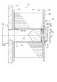
支持部22は、図2および図3に示すように、基端部221Eと先端部221Tとを有し、軸芯部材23における中空部の一端側(図3中左側)を先端部221T側から挿入することで、当該軸芯部材23を支持する円柱状の支持軸221と、当該支持軸221に挿入された軸芯部材23の図3中左方向への移動を規制する内ガイド板222とを備えている。支持軸221は、基端部221E側がフレーム21に形成された貫通孔21Aを貫通し、フレーム21の他方の面(図3中左面)に設けられた回転軸受BCにより、回転可能に支持されている。
As shown in FIGS. 2 and 3, the
支持軸221の先端部221Tには、支持軸221の軸線CE方向に突出して形成された破断手段24と、細軸部25とが備えられている。
The
破断手段24は、先端部221Tにおける先端面221Cの外縁に沿った形状に設けられ、軸芯部材23の一端側に設けられたデータキャリア29を破断可能な形状に形成されている。
The
細軸部25は、支持軸221に比べて細い円柱状であり、その軸線が、支持軸221の軸線CEと一致するよう設けられ、ガイド手段26を着脱可能に支持するようになっている。ガイド手段26は、細軸部25を挿通可能な挿入孔261を備えたボス263と、ボス263にねじ係合され、締め付けによってボス263の移動を規制する固定手段としてのクランパ262と、ボス263に取り付けられた外ガイド板264とを備えている。
外ガイド板264は、ボス263の挿入孔261の軸心CGに直交する面内に設けられ、軸芯部材23に対向する内ガイド面265(図3中左面)と、内ガイド面265の反対側の面である外ガイド面266(図3中右面)とを備え、導電体をループ状に巻回形成したループアンテナ27が、ボス263を囲うように外ガイド面266に設けられている。
The
The
また、ボス263には、ループアンテナ27に導電体281で接続された無線通信手段28が設けられている。この無線通信手段28は、制御手段6による制御に基づき、データキャリア29に記憶されたデータを読み取ったり、データキャリア29にデータを書き込んだりすることのできるリーダライタ7と赤外線、電波、磁力等により無線通信可能に設けられ、データキャリア29からループアンテナ27が受信もしくは読み取ったデータをリーダライタ7に無線送信する機能と、リーダライタ7から無線受信した信号をループアンテナ27に送信する機能とを備えている。
The
なお、データキャリア29とループアンテナ27とで通信するデータとしては、接着シートASの種類、材質、品名、コード、厚さ、長さ、幅、直径などの規格寸法、さらには、原反RSのロットナンバー、原反RSを使用した長さ、原反RSの残りの長さ、接着シートASの品質保証期限、繰出開始前後の接着シートASの残数、繰り出された接着シートASの枚数、接着シートASを最適に繰り出すことのできる推奨繰出速度、接着シートASを最適に貼付することができる推奨貼付張力や推奨押圧力などの接着シートASの貼付条件、接着シートASや原反RSについての相談窓口の連絡先などが例示できる。そして、貼付装置1に設けられた図示しないモニタにデータキャリア29から読み取ったデータを表示させたり、読み取ったデータを基に当該貼付装置1の貼付条件を設定したりすることができる。なお、ループアンテナ27を覆うように、ループアンテナ27を保護する保護部材を設けてもよい。
The data communicated between the
以上の貼付装置1において、ウェハWFに接着シートASを貼付する際には、まず、軸芯部材23に巻回された原反RSを支持軸221に支持させる。このとき、支持軸221が破断手段24を備えているので、データキャリア29のうち、軸芯部材23の一端側に設けられたデータキャリア29Aを破断することができる。そして、軸芯部材23が支持軸221に挿入されると、当該軸芯部材23の軸線CFが支持軸221の軸線CEと平行となる。
In the pasting device 1 described above, when the adhesive sheet AS is pasted on the wafer WF, first, the original fabric RS wound around the
次に、ボス263の挿入孔261に細軸部25を挿入して、クランパ262で締め付けて取り付けると、挿入孔261の軸心CGが支持軸221の軸線CEと平行となり、延いては軸芯部材23の軸線CFと挿入孔261の軸心CGとが平行となる。よって、それら軸線CF、CGに対して直交する面内に設けられたデータキャリア29Bとループアンテナ27とが対向することとなる。これにより、データキャリア29Bが支持軸221の軸線CE周りのどのような位置に取り付けられていても、データキャリア29Bとループアンテナ27とが対向した位置関係を維持可能となる。また、データキャリア29Bがループアンテナ27に対して軸線CE方向に位置ずれを起こし、それらが通信できなくなるような間隔となることを防止し、確実にそれらの通信距離を維持することができる。
なお、破断手段24により破断されたデータキャリア29Aは、軸芯部材23の内壁と支持軸221との隙間に折り曲げられるように入り込み、ループアンテナ27と対向することがないので、ループアンテナ27が2つのデータキャリア29A,29Bと通信(混信)することはない。
Next, when the
Note that the
この後、移動手段5が単軸ロボット53を駆動してテーブル51左方向に搬送させ、ウェハWFが所定の位置に達したことを図示しない光センサ等の検知手段が検知した時点で、繰出手段3が回動モータ35、39を駆動して接着シートASを繰り出し、押圧手段4が当該接着シートASを搬送されるウェハWFに押圧して貼付する。
Thereafter, the moving means 5 drives the single-
ここで、制御手段6は、貼付開始前にリーダライタ7を制御し、無線通信手段28に信号を送信する。信号を受信した無線通信手段28は、当該信号に基づき、ループアンテナ27に電流を流すことで磁束、静電気、マイクロ波等の伝送手段を発生させ、データキャリア29の導電性コイルを介して起電力を発生させ、データキャリア29Bに書きこまれたデータを読み取り、このデータを無線通信によりリーダライタ7に送信する。制御手段6は、リーダライタ7が受信した当該データに基づいて、貼付装置1全体を制御する。この制御は、例えば、データキャリア29Bに書き込まれたデータのうち、接着シートASの推奨繰出速度を基にして、回動モータ35、39の回転速度や、単軸ロボット53でテーブル51を移動させる移動速度を決定したり、推奨押圧力を基にして、押圧手段4を昇降させる図示しない直動モータの昇降量やその出力軸に加えるトルクなどを決定し、押圧力を設定したりすることができる。
このとき、ループアンテナ27とデータキャリア29Bの導電性コイルとが対向していることで、ループアンテナ27で発生する伝送手段の通過位置に導電性コイルを常時存在させることができるため、リーダライタ7は、ループアンテナ27を介して導電性コイルに効率よく起電力を発生させ、データキャリア29BのICチップに書き込まれたデータを確実に読み取ることができる。
Here, the control means 6 controls the reader / writer 7 before starting the pasting and transmits a signal to the wireless communication means 28. The wireless communication means 28 that has received the signal generates a transmission means such as magnetic flux, static electricity, or microwave by causing a current to flow through the
At this time, since the
また、制御手段6は、貼付開始後の軸芯部材23の回転中に、リーダライタ7を制御して、無線通信手段28を介してループアンテナ27に伝送手段を発生させ、上記同様に起電力を発生させてデータキャリア29Bにデータを書き込むこともできる。このように軸芯部材23が回転している場合であっても、データキャリア29Bの導電性コイルがループアンテナ27の伝送手段の通過位置に常時存在することとなり、リーダライタ7は、ループアンテナ27を介して導電性コイルに効率よく起電力を発生させ、データキャリア29Bのチップにデータを確実に書き込むことができる。このときに書き込むデータとしては、例えば、接着シートASを使用した枚数や、原反RSを使用した長さ等が例示できる。
Further, the control means 6 controls the reader / writer 7 during rotation of the
また、リーダライタ7は無線通信手段28を介してループアンテナ27と通信できるので、ループアンテナ27の回転に配慮した配線を行う必要がなく、配線の手間が省ける上、リーダライタ7を無線通信手段28と無線通信が可能な場所であれば任意の場所に設置できる。
そして、所定枚数のウェハWFに接着シートASが貼付し終わると、リーダライタ7を制御してデータキャリア29Bにデータを書き込むこともできる。このときに書き込むデータとしては、例えば、繰出開始前の接着シートASの残数から接着シートASを使用した枚数を差し引いた繰出開始後の接着シートASの残数や、原反RSの残りの長さ等が例示できる。なお、使用した接着シートASの数は、回動モータ35の起動回数や、ウェハWFが所定の位置に達したことを検知する図示しない検知手段が検知した回数等によって算出することができ、原反RSを使用した長さは、回動モータ35の回転数やパルス等によって算出することができる。このように、例えば、1の原反RSにおける接着シートASを全て使用してしまう前に、他の原反RSに型換えをする場合、1の原反RSのデータキャリア29Bにデータを書き込んでおくことによって、当該1の原反RSを再度使用するときに、上述と同様にしてデータを読み取ることで、即対応することができる。また、データキャリア29Bに記憶させた接着シートASの残数を、図示しない外部コンピュータに送信することで、原反RSの在庫を管理することもできる。
Further, since the reader / writer 7 can communicate with the
When the adhesive sheet AS is pasted on the predetermined number of wafers WF, the reader / writer 7 can be controlled to write data to the
以上のような本実施形態によれば、軸芯部材23が支持軸221に挿入され、細軸部25に外ガイド板264が固定されさえすれば、データキャリア29Bとループアンテナ27とを確実に対向させることができるので、従来のようにデータキャリア29Bとループアンテナ27との通信を適切に行うための正確な位置合わせを行う必要がなくなる。
According to the present embodiment as described above, as long as the
以上のように、本発明を実施するための最良の構成、方法等は、前記記載で開示されているが、本発明は、これに限定されるものではない。すなわち、本発明は、主に特定の実施形態に関して特に図示され、かつ説明されているが、本発明の技術的思想および目的の範囲から逸脱することなく、以上述べた実施形態に対し、形状、材質、数量、その他の詳細な構成において、当業者が様々な変形を加えることができるものである。また、上記に開示した形状、材質などを限定した記載は、本発明の理解を容易にするために例示的に記載したものであり、本発明を限定するものではないから、それらの形状、材質などの限定の一部もしくは全部の限定を外した部材の名称での記載は、本発明に含まれるものである。 As described above, the best configuration, method and the like for carrying out the present invention have been disclosed in the above description, but the present invention is not limited to this. That is, the invention has been illustrated and described with particular reference to certain specific embodiments, but without departing from the spirit and scope of the invention, Various modifications can be made by those skilled in the art in terms of material, quantity, and other detailed configurations. In addition, the description of the shape, material, and the like disclosed above is exemplary for ease of understanding of the present invention, and does not limit the present invention. The description by the name of the member which remove | excluded the limitation of one part or all of such restrictions is included in this invention.
例えば、ループアンテナ27をボス263と外ガイド板264との間に設けてもよい。
さらに、ループアンテナ27は、細軸部25を囲うことのない位置に形成してもよい。
また、外ガイド板264を無線通信手段28とリーダライタ7との通信に利用される電波帯や電磁波およびループアンテナ27とデータキャリア29Bとの通信に利用される電磁波を遮蔽可能な素材で構成すれば、当該通信が互いに妨げられることなく、より適切に通信を行うことができる。
For example, the
Further, the
Further, the
また、支持軸221をフレーム21に対して回転不可能に設け、軸芯部材23が支持軸221に対して回転するようにしてもよい。
Further, the
また、破断手段24の形状は、データキャリア29を破断可能な形状であれば、特に制限はなく、図2、図3で図示した形状以外のものを用いることができる。
さらに、支持軸221の基端部221Eに駆動機器としての回動モータを接続し、支持軸221自らが回転駆動するようにしてもよい。
また、前記実施形態では、支持装置2として軸芯部材23に巻回された原反RSを繰出可能に支持する場合を例示したが、支持装置2としては、軸芯部材27に各種長尺体を巻取可能に支持するものであってもよく、例えば、前記実施形態の回収ローラ38に軸芯部材23を固定して剥離シートRLを巻き取る構成のものが例示できる。
さらに、データキャリア29は、軸芯部材23の他端側にだけ配置されていてもよいし、各端面231に一個または複数個配置されていてもよい。
また、データキャリア29は、データの記憶のみができるものであってもよいし、データの送信のみができるものであってもよく、例えば、バーコードやQRコード(登録商標)や磁気シートとしてもよい。この際、通信部として、ループアンテナ27の代わりに、バーコードやQRコードを読み取り可能なリーダを設ければよいし、磁気シートの場合、磁界を発生させて磁性体を磁化してデータを書き込んだり、磁界の変化を検知してデータを読み出したりするいわゆる磁気ヘッドを使用すればよい。なお、バーコードやQRコードのように記憶する情報量が少ないものの場合は、これらコードに上位のコンピュータ等の上位の制御手段にアクセスできるコードを記憶させておき、当該上位の制御手段から上記同様のデータを受信するようにしてもよい。
さらに、データキャリア29は、D形状以外に丸形状、三角形状、四角形状、等の形状であってよいし、端面231における開口を全て覆うような形状のものであって、ガイド手段を取り付けることができる孔を有するようなものであってもよい。
The shape of the breaking means 24 is not particularly limited as long as the
Furthermore, a rotation motor as a driving device may be connected to the
Moreover, in the said embodiment, although the case where the raw fabric RS wound by the
Furthermore, the
The
Further, the
また、ループアンテナ27やデータキャリア29は、少々湾曲した面内や折れ曲がった面内に設けるようにしてもよい。要は、ループアンテナ27とデータキャリア29とが対向し、データキャリア29が支持軸221の軸心CE周りに位置ずれを起こしても、それらの対向した位置関係を維持可能であればよい。
前記実施形態では、軸芯部材23の軸線CFに直交する面内にデータキャリア29を設けた例を挙げたが、データキャリア29を当該軸線CFに対して60度傾けた状態で軸芯部材23に設けた場合にでも、支持軸221の軸線CEに直交する先端面221Cに設けたループアンテナ27と通信できることが実証できた。
さらに、バーコードを軸線CFに対して30度傾けた状態で軸芯部材23に設けた場合(ピッチ角30度)にでも、支持軸221の軸線CEに直交する先端面221Cに読取面を設けたバーコードリーダと通信できることが実証できた。なお、QRコードの場合、同角度は65度(ピッチ角65度)で通信できることが実証できた。
Further, the
In the above-described embodiment, the example in which the
Further, even when the barcode is provided on the
また、前記実施形態では、支持軸221の軸線CEに直交する先端面221Cにループアンテナ27を設けた例を挙げたが、ループアンテナ27を当該軸線CEに対して60度傾けた状態で支持軸221に設けた場合にでも、軸芯部材23の軸線CFに直交する面内に設けたデータキャリア29と通信できることが実証できた。
さらに、バーコードリーダの読取面を軸線CEに対して30度傾けた状態で支持軸221に設けた場合にでも、軸芯部材23の軸線CFに直交する面内に設けたバーコードと通信できることが実証できた(ピッチ角30度)。なお、QRコードの場合、同角度は65度で通信できることが実証できた(ピッチ角65度)。
In the embodiment, the example in which the
Further, even when the reading surface of the barcode reader is provided on the
また、長尺体としては、原反RSに限定されず、帯状の接着シート、紙、布、鋼板、ベルト、樹脂、木板などであってもよく、長尺の糸、紐、針金、コード、チューブ、ホースなどであってもよい。 Further, the long body is not limited to the raw fabric RS, and may be a belt-like adhesive sheet, paper, cloth, steel plate, belt, resin, wood board, etc., and a long thread, string, wire, cord, A tube, a hose, etc. may be sufficient.
さらに、本発明における接着シートASの種別や材質などは、特に限定されず、例えば、基材シートBSと接着剤層ADとの間に中間層を有するものや、他の層を有する等3層以上のものでもよい。また、接着シートASは、保護シート、ダイシングテープ、ダイアタッチフィルムなどであってもよい。半導体ウェハは、シリコン半導体ウェハや化合物半導体ウェハ等が例示でき、このような半導体ウェハに貼付する接着シートは、保護シート、ダイシングテープ、ダイアタッチフィルムに限らず、その他の任意のシート、フィルム、テープ等、任意の用途、形状の接着シート等が適用できる。さらに、板状部材が光ディスクの基板であって、接着シートが記録層を構成する樹脂層を有したものであってもよい。以上のように、板状部材としては、ガラス板、鋼板、樹脂板等や、その他の部材のみならず、任意の形態の部材や物品なども対象とすることができる。
また、押圧手段4は、前記実施形態で示したもの以外のもので構成してもよく、押圧手段4は板状部材に接着シートが貼付できる限りにおいて何ら限定されるものではなく、例えば、ブレード材、エア噴き付け、ゴム、樹脂、スポンジ等による押圧部材を採用することができる。
Furthermore, the type and material of the adhesive sheet AS in the present invention are not particularly limited. For example, the adhesive sheet AS has an intermediate layer between the base sheet BS and the adhesive layer AD, or has three other layers. The above may be used. The adhesive sheet AS may be a protective sheet, a dicing tape, a die attach film, or the like. Examples of the semiconductor wafer include a silicon semiconductor wafer and a compound semiconductor wafer. The adhesive sheet to be attached to such a semiconductor wafer is not limited to a protective sheet, a dicing tape, and a die attach film, but any other sheet, film, or tape. An adhesive sheet having an arbitrary use and shape can be applied. Further, the plate member may be an optical disk substrate, and the adhesive sheet may have a resin layer constituting the recording layer. As described above, as a plate-like member, not only a glass plate, a steel plate, a resin plate, and other members, but also members and articles of any form can be targeted.
Further, the
また、前記実施形態における駆動機器は、回動モータ、直動モータ、リニアモータ、単軸ロボット、多関節ロボット等の電動機器、エアシリンダ、油圧シリンダ、ロッドレスシリンダおよびロータリシリンダ等のアクチュエータ等を採用することができる上、それらを直接的又は間接的に組み合せたものを採用することもできる(実施形態で例示したものと重複するものもある)。 The drive device in the embodiment includes an electric device such as a rotation motor, a linear motion motor, a linear motor, a single axis robot, an articulated robot, an actuator such as an air cylinder, a hydraulic cylinder, a rodless cylinder, and a rotary cylinder. In addition to these, a combination of them directly or indirectly may be employed (some of them overlap with those exemplified in the embodiment).
2…支持装置
21…フレーム
24…破断手段
26…ガイド手段
27…ループアンテナ(通信部)
28…無線通信手段
29(29A,29B)…データキャリア
221…支持軸
221E…基端部
221T…先端部
CE,CF,CG…軸線
RS…原反(長尺体)
2 ...
28 ... wireless communication means 29 (29A, 29B) ...
Claims (3)
基端部と先端部とを有し、前記軸芯部材における中空部の一端側を当該先端部側から挿入することで当該軸芯部材を支持する支持軸と、
前記支持軸を前記基端部側から支えるフレームと、
前記支持軸の先端部に着脱可能に設けられ、当該先端部に取り付けることにより前記軸芯部材の位置決めが可能なガイド手段とを備え、
前記軸芯部材には、中空部の他端側であって当該軸芯部材の軸線に交差する面内に、所定のデータの記憶および送信の少なくとも一方が可能なデータキャリアが設けられ、
前記ガイド手段には、前記支持軸の先端部に固定されたときに、前記データキャリアと対向して配置され、当該データキャリアと通信可能な通信部が設けられていることを特徴とする長尺体の支持装置。 In a long body support device that supports a long body wound around a hollow cylindrical shaft core member so that the long body can be drawn out, or supports a long body wound around a hollow cylindrical shaft core member,
A support shaft that has a proximal end portion and a distal end portion, and supports the shaft core member by inserting one end side of the hollow portion of the shaft core member from the distal end portion side;
A frame that supports the support shaft from the base end side;
A guide means that is detachably provided at the distal end portion of the support shaft, and capable of positioning the shaft core member by being attached to the distal end portion;
The shaft core member is provided with a data carrier capable of at least one of storing and transmitting predetermined data in a plane that intersects the axis of the shaft core member on the other end side of the hollow portion.
The guide means is provided with a communication unit that is arranged to face the data carrier and is communicable with the data carrier when fixed to the tip of the support shaft. Body support device.
前記軸芯部材における中空部の他端側であって当該軸芯部材の軸線に交差する面内に、所定のデータの記憶および送信の少なくとも一方が可能なデータキャリアが設けられた軸芯部材を用意する工程と、
前記軸芯部材における中空部の一端側を支持軸の先端部側から挿入して当該軸芯部材を支持する工程と、
前記支持軸の先端部に前記軸芯部材の位置決めが可能なガイド手段を取り付けることで、当該ガイド手段に設けられた通信部と前記データキャリアとを対向させて支持する工程と、
前記通信部とデータキャリアとで通信を行う工程とを有することを特徴とする長尺体の支持方法。 In a long body support method for supporting a long body wound around a hollow cylindrical shaft core member so that the long body can be drawn out or supported on a hollow cylindrical shaft core member so that the long body can be wound up,
A shaft core member provided with a data carrier capable of at least one of storing and transmitting predetermined data in a plane intersecting the axis of the shaft core member on the other end side of the hollow portion of the shaft core member. A process to prepare;
Inserting one end side of the hollow portion in the shaft core member from the tip end side of the support shaft to support the shaft core member;
Attaching the guide means capable of positioning the shaft core member to the distal end portion of the support shaft, and supporting the communication section provided in the guide means and the data carrier opposite to each other;
And a step of performing communication between the communication unit and the data carrier.
Priority Applications (1)
| Application Number | Priority Date | Filing Date | Title |
|---|---|---|---|
| JP2011262601A JP6050936B2 (en) | 2011-11-30 | 2011-11-30 | Long body support device |
Applications Claiming Priority (1)
| Application Number | Priority Date | Filing Date | Title |
|---|---|---|---|
| JP2011262601A JP6050936B2 (en) | 2011-11-30 | 2011-11-30 | Long body support device |
Publications (2)
| Publication Number | Publication Date |
|---|---|
| JP2013115366A true JP2013115366A (en) | 2013-06-10 |
| JP6050936B2 JP6050936B2 (en) | 2016-12-21 |
Family
ID=48710607
Family Applications (1)
| Application Number | Title | Priority Date | Filing Date |
|---|---|---|---|
| JP2011262601A Active JP6050936B2 (en) | 2011-11-30 | 2011-11-30 | Long body support device |
Country Status (1)
| Country | Link |
|---|---|
| JP (1) | JP6050936B2 (en) |
Cited By (2)
| Publication number | Priority date | Publication date | Assignee | Title |
|---|---|---|---|---|
| JP2017069268A (en) * | 2015-09-28 | 2017-04-06 | リンテック株式会社 | Sheet manufacturing device and manufacturing method and sheet pasting device and pasting method |
| KR20190001913A (en) * | 2017-06-28 | 2019-01-07 | 가부시기가이샤 디스코 | Tape applier and method for removing tape |
Citations (13)
| Publication number | Priority date | Publication date | Assignee | Title |
|---|---|---|---|---|
| JP2000154673A (en) * | 1998-09-17 | 2000-06-06 | A I Technol:Kk | Safekeeping control device for deleterious poisonous substance and electronic weighing instrument therefor |
| JP2000313558A (en) * | 1999-04-30 | 2000-11-14 | Copyer Co Ltd | Image forming device |
| JP2000344424A (en) * | 1999-06-01 | 2000-12-12 | Fuji Photo Film Co Ltd | Information recording paper roll and distinguishing method for information recording paper |
| JP2001354343A (en) * | 2000-06-14 | 2001-12-25 | Sato Corp | Belt-like roll body, printer, and method of printing |
| JP2003266023A (en) * | 2002-03-18 | 2003-09-24 | Ishii Ind Co Ltd | Article sorting system |
| US20030189125A1 (en) * | 2002-04-03 | 2003-10-09 | Christian Trierenberg | Spool for windable materials |
| JP2004255701A (en) * | 2003-02-26 | 2004-09-16 | Riso Kagaku Corp | Stencil original paper roll |
| JP2006011012A (en) * | 2004-06-25 | 2006-01-12 | Fuji Xerox Co Ltd | Wireless tag holder for rotatable part, electrophotographic photoreceptor with wireless tag holder, and process cartridge with wireless tag holder |
| JP2007261769A (en) * | 2006-03-29 | 2007-10-11 | Seiko Epson Corp | Supporting member for rolled paper and rolled paper unit |
| JP2007261132A (en) * | 2006-03-29 | 2007-10-11 | Seiko Epson Corp | Communication control unit, and management system and management method for roll paper |
| JP2009262365A (en) * | 2008-04-23 | 2009-11-12 | Seiko Epson Corp | Printing apparatus |
| JP2011195204A (en) * | 2010-03-17 | 2011-10-06 | Seiko Epson Corp | Roll paper supply device |
| JP2012045741A (en) * | 2010-08-25 | 2012-03-08 | Toshiba Tec Corp | Printer and roll |
-
2011
- 2011-11-30 JP JP2011262601A patent/JP6050936B2/en active Active
Patent Citations (13)
| Publication number | Priority date | Publication date | Assignee | Title |
|---|---|---|---|---|
| JP2000154673A (en) * | 1998-09-17 | 2000-06-06 | A I Technol:Kk | Safekeeping control device for deleterious poisonous substance and electronic weighing instrument therefor |
| JP2000313558A (en) * | 1999-04-30 | 2000-11-14 | Copyer Co Ltd | Image forming device |
| JP2000344424A (en) * | 1999-06-01 | 2000-12-12 | Fuji Photo Film Co Ltd | Information recording paper roll and distinguishing method for information recording paper |
| JP2001354343A (en) * | 2000-06-14 | 2001-12-25 | Sato Corp | Belt-like roll body, printer, and method of printing |
| JP2003266023A (en) * | 2002-03-18 | 2003-09-24 | Ishii Ind Co Ltd | Article sorting system |
| US20030189125A1 (en) * | 2002-04-03 | 2003-10-09 | Christian Trierenberg | Spool for windable materials |
| JP2004255701A (en) * | 2003-02-26 | 2004-09-16 | Riso Kagaku Corp | Stencil original paper roll |
| JP2006011012A (en) * | 2004-06-25 | 2006-01-12 | Fuji Xerox Co Ltd | Wireless tag holder for rotatable part, electrophotographic photoreceptor with wireless tag holder, and process cartridge with wireless tag holder |
| JP2007261769A (en) * | 2006-03-29 | 2007-10-11 | Seiko Epson Corp | Supporting member for rolled paper and rolled paper unit |
| JP2007261132A (en) * | 2006-03-29 | 2007-10-11 | Seiko Epson Corp | Communication control unit, and management system and management method for roll paper |
| JP2009262365A (en) * | 2008-04-23 | 2009-11-12 | Seiko Epson Corp | Printing apparatus |
| JP2011195204A (en) * | 2010-03-17 | 2011-10-06 | Seiko Epson Corp | Roll paper supply device |
| JP2012045741A (en) * | 2010-08-25 | 2012-03-08 | Toshiba Tec Corp | Printer and roll |
Cited By (3)
| Publication number | Priority date | Publication date | Assignee | Title |
|---|---|---|---|---|
| JP2017069268A (en) * | 2015-09-28 | 2017-04-06 | リンテック株式会社 | Sheet manufacturing device and manufacturing method and sheet pasting device and pasting method |
| KR20190001913A (en) * | 2017-06-28 | 2019-01-07 | 가부시기가이샤 디스코 | Tape applier and method for removing tape |
| KR102562870B1 (en) | 2017-06-28 | 2023-08-02 | 가부시기가이샤 디스코 | Tape applier and method for removing tape |
Also Published As
| Publication number | Publication date |
|---|---|
| JP6050936B2 (en) | 2016-12-21 |
Similar Documents
| Publication | Publication Date | Title |
|---|---|---|
| JP6105312B2 (en) | Support device and data management method | |
| JP5856396B2 (en) | Belt-like sheet supporting apparatus and supporting method | |
| JP6050936B2 (en) | Long body support device | |
| JP5767095B2 (en) | Data carrier and elongated shaft core member | |
| JP5856452B2 (en) | Long body support device | |
| JP5860275B2 (en) | Long body support apparatus and support method | |
| JP5856397B2 (en) | Shaft core member | |
| JP5775801B2 (en) | Data carrier and elongated shaft core member | |
| JP2013203543A (en) | Winding device and winding method | |
| JP5856398B2 (en) | Belt-like sheet support device | |
| JP2012185674A (en) | Printer and writing method of printer | |
| JP5889652B2 (en) | Support device | |
| TWI666726B (en) | Supporting device for strip-shaped sheet and management method of strip-shaped sheet | |
| JP5913936B2 (en) | Method of using adhesive sheet for fixing wound material and adhesive sheet for fixing wound material | |
| JP2021143034A (en) | Winding device and winding method | |
| JP2013038256A (en) | Sheet application apparatus and sheet application method | |
| JP4754399B2 (en) | Printer | |
| JP2019034802A (en) | Lengthy article conveying device and conveying method of lengthy article | |
| JP2017107946A (en) | Sheet peeling device | |
| JPH0330980A (en) | Ink sheet cassette and recording apparatus using the same |
Legal Events
| Date | Code | Title | Description |
|---|---|---|---|
| A621 | Written request for application examination |
Free format text: JAPANESE INTERMEDIATE CODE: A621 Effective date: 20140807 |
|
| A977 | Report on retrieval |
Free format text: JAPANESE INTERMEDIATE CODE: A971007 Effective date: 20150512 |
|
| A131 | Notification of reasons for refusal |
Free format text: JAPANESE INTERMEDIATE CODE: A131 Effective date: 20150519 |
|
| A131 | Notification of reasons for refusal |
Free format text: JAPANESE INTERMEDIATE CODE: A131 Effective date: 20151208 |
|
| A02 | Decision of refusal |
Free format text: JAPANESE INTERMEDIATE CODE: A02 Effective date: 20160705 |
|
| A521 | Request for written amendment filed |
Free format text: JAPANESE INTERMEDIATE CODE: A523 Effective date: 20160930 |
|
| A911 | Transfer to examiner for re-examination before appeal (zenchi) |
Free format text: JAPANESE INTERMEDIATE CODE: A911 Effective date: 20161011 |
|
| TRDD | Decision of grant or rejection written | ||
| A01 | Written decision to grant a patent or to grant a registration (utility model) |
Free format text: JAPANESE INTERMEDIATE CODE: A01 Effective date: 20161115 |
|
| A61 | First payment of annual fees (during grant procedure) |
Free format text: JAPANESE INTERMEDIATE CODE: A61 Effective date: 20161128 |
|
| R150 | Certificate of patent or registration of utility model |
Ref document number: 6050936 Country of ref document: JP Free format text: JAPANESE INTERMEDIATE CODE: R150 |
|
| R250 | Receipt of annual fees |
Free format text: JAPANESE INTERMEDIATE CODE: R250 |
|
| R250 | Receipt of annual fees |
Free format text: JAPANESE INTERMEDIATE CODE: R250 |
|
| R250 | Receipt of annual fees |
Free format text: JAPANESE INTERMEDIATE CODE: R250 |
|
| R250 | Receipt of annual fees |
Free format text: JAPANESE INTERMEDIATE CODE: R250 |
|
| R250 | Receipt of annual fees |
Free format text: JAPANESE INTERMEDIATE CODE: R250 |