JP2013110012A - Multidirectional operation type electronic component - Google Patents

Multidirectional operation type electronic component Download PDF

Info

Publication number
JP2013110012A
JP2013110012A JP2011255120A JP2011255120A JP2013110012A JP 2013110012 A JP2013110012 A JP 2013110012A JP 2011255120 A JP2011255120 A JP 2011255120A JP 2011255120 A JP2011255120 A JP 2011255120A JP 2013110012 A JP2013110012 A JP 2013110012A
Authority
JP
Japan
Prior art keywords
electronic component
holding base
holding
swinging
operation knob
Prior art date
Legal status (The legal status is an assumption and is not a legal conclusion. Google has not performed a legal analysis and makes no representation as to the accuracy of the status listed.)
Granted
Application number
JP2011255120A
Other languages
Japanese (ja)
Other versions
JP5766101B2 (en
Inventor
Yuki Nagai
祐樹 永井
Osamu Nomura
修 野村
Yoshiyuki Kawato
義之 川嶌
Current Assignee (The listed assignees may be inaccurate. Google has not performed a legal analysis and makes no representation or warranty as to the accuracy of the list.)
Teikoku Tsushin Kogyo Co Ltd
Original Assignee
Teikoku Tsushin Kogyo Co Ltd
Priority date (The priority date is an assumption and is not a legal conclusion. Google has not performed a legal analysis and makes no representation as to the accuracy of the date listed.)
Filing date
Publication date
Application filed by Teikoku Tsushin Kogyo Co Ltd filed Critical Teikoku Tsushin Kogyo Co Ltd
Priority to JP2011255120A priority Critical patent/JP5766101B2/en
Publication of JP2013110012A publication Critical patent/JP2013110012A/en
Application granted granted Critical
Publication of JP5766101B2 publication Critical patent/JP5766101B2/en
Expired - Fee Related legal-status Critical Current
Anticipated expiration legal-status Critical

Links

Images

Landscapes

  • Switches With Compound Operations (AREA)

Abstract

【課題】操作つまみを略直交する二つの方向に向けて異なる操作感触にて操作できる多方向操作型電子部品を提供すること。
【解決手段】操作つまみ20を一定の方向Cに揺動することで出力信号を変化させる電子部品10と、電子部品10を載置する保持台本体部210と保持体本体部210の外周辺の対向する位置から突出する一対の可撓性を有するヒンジ部250とヒンジ部250の先端に取り付けられる取付部260とを有し一対のヒンジ部250を結ぶ軸を揺動軸Lとしてねじることで保持台本体部210を揺動させる保持台200と、保持台200の下面側であって保持台本体部210が揺動に伴って上下動する位置に配置される押圧式スイッチ340とを有する。操作つまみ20が揺動する向きCと、保持台本体部210が揺動する向きDとを略直交するように電子部品10を保持台本体部210上に設置する。
【選択図】図7
The present invention provides a multi-directional operation type electronic component in which an operation knob can be operated with different operation feelings in two directions substantially orthogonal to each other.
An electronic component 10 that changes an output signal by swinging an operation knob 20 in a fixed direction C, a holding base body 210 on which the electronic component 10 is placed, and an outer periphery of the holding body main body 210 are provided. A pair of flexible hinges 250 projecting from opposing positions and a mounting part 260 attached to the tip of the hinge part 250 and having an axis connecting the pair of hinge parts 250 as a swing axis L are held by twisting. A holding base 200 that swings the base body 210 and a pressing switch 340 that is disposed on the lower surface side of the holding base 200 and at a position where the base body 210 moves up and down as it swings. The electronic component 10 is installed on the holding base body 210 so that the direction C in which the operation knob 20 swings and the direction D in which the holding base body 210 swings are substantially orthogonal.
[Selection] Figure 7

Description

本発明は、操作つまみを略直交する二つの方向に向けて操作することでその出力信号を変化させる多方向操作型電子部品に関するものである。   The present invention relates to a multidirectional operation type electronic component that changes its output signal by operating an operation knob in two directions substantially orthogonal to each other.

従来、例えば特許文献1に示すように、回転つまみ(10)を回転することでその出力信号を変化させ、一方回転つまみ(10)の上面の4か所をその上方から押圧することで回転つまみ(10)自体を揺動して押圧スイッチ(185)をオンする構造の多方向操作型電子部品がある。また例えば特許文献2に示すように、操作つまみ(50)を直交する4方向に揺動することで4つのスイッチ72をオンする構造の多方向操作型電子部品もある。   Conventionally, as shown, for example, in Patent Document 1, the output signal is changed by rotating the rotary knob (10), and the rotary knob (10) is pressed from above by rotating four places on the upper surface of the rotary knob (10). (10) There is a multi-directional operation type electronic component having a structure in which the push switch (185) is turned on by swinging itself. For example, as shown in Patent Document 2, there is also a multidirectional operation type electronic component having a structure in which four switches 72 are turned on by swinging an operation knob (50) in four orthogonal directions.

一方、例えば携帯型のビデオカメラのズーム操作用入力手段等に用いて好適な電子部品として、例えば特許文献3に示すように、つまみ(200)を揺動する揺動量に応じて出力信号を変化させる構造の電子部品がある。   On the other hand, as an electronic component suitable for, for example, an input means for zoom operation of a portable video camera, for example, as shown in Patent Document 3, the output signal is changed in accordance with the amount of swing of the knob (200). There are electronic parts with a structure to let you.

特開2011−134574号公報JP 2011-134574 A 特開2006−331699号公報JP 2006-331699 A 特開2010−10384号公報JP 2010-10384 A

そして従来、操作つまみを直交する二つの方向に向けて操作することでその出力信号を変化させる多方向操作型電子部品であって、且つ操作つまみを一方の方向へ揺動させた際は移動量に応じた出力が得られ、直交するもう一方の方向へ揺動させた際はスイッチのオンオフ出力が得られる、構造の簡単な多方向操作型電子部品はなかった。   Conventionally, it is a multi-directional electronic component that changes its output signal by operating the operation knob in two orthogonal directions, and the amount of movement when the operation knob is swung in one direction There was no multidirectional operation type electronic component with a simple structure in which an output corresponding to the output was obtained and an on / off output of the switch was obtained when it was swung in the other direction orthogonal to each other.

本発明は上述の点に鑑みてなされたものでありその目的は、操作つまみを略直交する二つの方向に向けて操作することでその出力信号を変化させることができ、且つ操作つまみを一方の方向へ操作した際の出力の状態ともう一方の方向へ操作した際の出力の状態とを容易に異ならせることができる、構造の簡単な多方向操作型電子部品を提供することにある。   The present invention has been made in view of the above-described points, and an object of the present invention is to change the output signal by operating the operation knob in two directions substantially orthogonal to each other. It is an object of the present invention to provide a multi-directional operation type electronic component having a simple structure in which an output state when operated in one direction and an output state when operated in the other direction can be easily different.

本願請求項1に記載の発明は、操作つまみを一定の方向に揺動又は略直線移動することで出力信号を変化させる電子部品と、前記電子部品を載置する保持台本体部と保持体本体部の外周辺の対向する位置から突出する少なくとも一対の可撓性を有するヒンジ部とヒンジ部の先端側部分に取り付けられる取付部とを有しこれによって前記一対のヒンジ部を結ぶ軸を揺動軸として前記保持台本体部を揺動させる保持台と、前記保持台の前記電子部品を載置した反対面側であって前記保持台本体部が前記揺動に伴って上下動する位置に配置される押圧式スイッチと、を有し、前記操作つまみが揺動又は略直線移動する向きと、前記保持台本体部の揺動する向きとが略直交するように前記電子部品を保持台本体部上に設置し、前記操作つまみを揺動又は略直線移動して電子部品の出力信号を変化させる際は前記保持台本体部が静止し、一方前記操作つまみを前記揺動又は略直線移動方向に対して略直交する方向に揺動する際は前記保持台本体部がその揺動軸を中心に揺動して前記押圧式スイッチを押圧操作することを特徴とする多方向操作型電子部品にある。   According to the first aspect of the present invention, there are provided an electronic component that changes an output signal by swinging or substantially linearly moving an operation knob in a fixed direction, a holding base body portion on which the electronic component is placed, and a holding body main body. And at least a pair of flexible hinges projecting from opposing positions on the outer periphery of the part and a mounting part attached to the tip side part of the hinge part, thereby swinging the shaft connecting the pair of hinge parts A holding base for swinging the holding base main body as an axis, and a position on the opposite side of the holding base on which the electronic component is placed, at a position where the holding base main body moves up and down with the swing And the holding base body portion so that the direction in which the operation knob swings or moves substantially linearly and the direction in which the holding base body portion swings are substantially orthogonal to each other. Install the control knob on the When changing the output signal of the electronic component by moving substantially linearly, the holding base body is stationary, while when swinging the operation knob in the direction substantially perpendicular to the swinging or substantially linear moving direction. The multi-directional operation type electronic component is characterized in that the holding base main body swings about a swing shaft to press the pressing switch.

本願請求項2に記載の発明は、請求項1に記載の多方向操作型電子部品であって、前記保持台の取付部と前記押圧式スイッチとを載置する基台をさらに有し、前記保持台本体部の前記基台を設置した側の面に、先端が前記基台に直接又は他の部材を介して対向して保持台本体部をその揺動方向に揺動自在に支持する支持突起を設けたことを特徴とする多方向操作型電子部品にある。   The invention according to claim 2 of the present application is the multi-directional operation type electronic component according to claim 1, further comprising a base on which the mounting portion of the holding base and the pressing switch are placed, Support for supporting the holding base body part so that the holding base body part can swing freely in the swinging direction with the tip of the holding base body part facing the base directly or via another member on the surface on which the base is installed A multi-directional electronic component having a protrusion is provided.

本願請求項3に記載の発明は、請求項2に記載の多方向操作型電子部品であって、前記押圧式スイッチは、前記揺動軸を挟んだ両側の対向する位置に一対設けられていることを特徴とする多方向操作型電子部品にある。   The invention according to claim 3 of the present application is the multi-directional operation type electronic component according to claim 2, wherein a pair of the push-type switches are provided at opposite positions on both sides of the swing shaft. The multi-directional operation type electronic component is characterized in that.

請求項1に記載の発明によれば、揺動式又はスライド式の電子部品の操作つまみを、通常の操作方向へ操作することによって出力信号が変化できると共に、前記操作方向に略直交する方向へ揺動操作することによって別の押圧式スイッチを操作できる。つまり揺動式又はスライド式の電子部品の操作つまみを略直交する二つの方向に移動することで、揺動式又はスライド式電子部品の出力と、押圧式スイッチの出力、即ち異なる種類の出力信号を得ることができる。さらに前記操作つまみの一方の方向への操作感触と、もう一方の方向への操作感触とを容易に異ならせることができる。
また請求項1に記載の発明によれば、上記機能を有する多方向操作型電子部品を、保持台と押圧式スイッチを追加するという簡単な構成で実現できる。
また請求項1に記載の発明によれば、操作つまみの揺動又は略直線移動する向きと、保持台本体部の揺動する向きとを略直交するように、電子部品を保持台本体部上に設置したので、別途特別の機構を設けなくても、操作つまみを揺動又は略直線移動して電子部品の出力信号を変化させる際は保持台本体部の揺動を防止でき、一方操作つまみの前記揺動又は略直線移動方向に略直交する方向に揺動して押圧式スイッチを押圧操作する際は操作つまみの前記揺動又は略直線移動を防止できる。
According to the first aspect of the present invention, the output signal can be changed by operating the operation knob of the swing type or slide type electronic component in the normal operation direction, and in a direction substantially orthogonal to the operation direction. Another push switch can be operated by swinging. In other words, by moving the operation knob of the swinging or sliding electronic component in two directions that are substantially orthogonal, the output of the swinging or sliding electronic component and the output of the push switch, that is, different types of output signals Can be obtained. Furthermore, the operation feeling in one direction of the operation knob can be easily made different from the operation feeling in the other direction.
According to the first aspect of the present invention, the multi-directional operation type electronic component having the above function can be realized with a simple configuration in which a holding base and a push switch are added.
According to the first aspect of the present invention, the electronic component is mounted on the holding base body so that the swinging direction of the operation knob or the substantially linear movement direction is substantially orthogonal to the swinging direction of the holding base body. Therefore, it is possible to prevent the holding base body from swinging when changing the output signal of an electronic component by swinging or moving substantially linearly without providing a special mechanism. When the pressing switch is pressed by swinging in the direction substantially perpendicular to the swinging or substantially linear movement direction, the swinging or the substantially linear movement of the operation knob can be prevented.

請求項2に記載の発明によれば、保持台本体部に支持突起を設けたので、保持台本体部の揺動方向への揺動動作がよりスムースに行えるようになる。   According to the second aspect of the present invention, since the support protrusion is provided on the holding base body, the swinging operation of the holding base body in the swinging direction can be performed more smoothly.

請求項3に記載の発明によれば、操作つまみの操作によって、左右一対の押圧式スイッチを操作することができる。   According to the third aspect of the present invention, the pair of left and right push switches can be operated by operating the operation knob.

多方向操作型電子部品1の斜視図である。1 is a perspective view of a multi-directional operation type electronic component 1. FIG. 多方向操作型電子部品1の分解斜視図(その上側の部品を示す)である。It is a disassembled perspective view of the multidirectional operation type electronic component 1 (showing the upper part thereof). 多方向操作型電子部品1の分解斜視図(その下側の部品を示す)である。1 is an exploded perspective view of a multi-directional operation type electronic component 1 (showing its lower component). 操作つまみ20と第1保持体50と移動体100と第2保持体150とを下側から見た斜視図である。It is the perspective view which looked at the operation knob 20, the 1st holding body 50, the moving body 100, and the 2nd holding body 150 from the lower side. 保持台200を下側から見た斜視図である。It is the perspective view which looked at the holding stand 200 from the lower side. 図1のA−A断面図である。It is AA sectional drawing of FIG. 図1のB−B断面図である。It is BB sectional drawing of FIG. 保持台200の他の実施形態を示す平面図である。It is a top view which shows other embodiment of the holding stand.

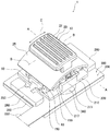
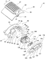
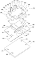
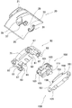
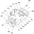
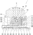
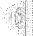
以下、本発明の実施形態を図面を参照して詳細に説明する。図1は本発明の1実施形態に係る多方向操作型電子部品1の斜視図、図2は多方向操作型電子部品1の分解斜視図(その上側の部品を示す)、図3は多方向操作型電子部品1の分解斜視図(その下側の部品を示す)、図4は多方向操作型電子部品1を構成する操作つまみ20と第1保持体50と移動体100と第2保持体150とを下側から見た斜視図、図5は保持台200を下側から見た斜視図、図6は図1のA−A断面図、図7は図1のB−B断面図である。なお以下の説明において、「上」とは保持台200から操作つまみ20を見る方向をいい、「下」とはその反対方向をいうものとする。   Hereinafter, embodiments of the present invention will be described in detail with reference to the drawings. FIG. 1 is a perspective view of a multidirectional operation type electronic component 1 according to an embodiment of the present invention, FIG. 2 is an exploded perspective view of the multidirectional operation type electronic component 1 (showing the upper part thereof), and FIG. FIG. 4 is an exploded perspective view of the operation-type electronic component 1 (showing its lower component), and FIG. 4 shows the operation knob 20, the first holding body 50, the moving body 100, and the second holding body constituting the multidirectional operation-type electronic component 1. FIG. 5 is a perspective view of the holding base 200 viewed from below, FIG. 6 is a sectional view taken along line AA in FIG. 1, and FIG. 7 is a sectional view taken along line BB in FIG. is there. In the following description, “up” refers to the direction in which the operation knob 20 is viewed from the holding base 200, and “down” refers to the opposite direction.

多方向操作型電子部品1は、図2、図3に示すように、基台350上に、回路基板(以下「フレキシブル回路基板」という)300と保持台200と電子部品10を設置して構成されている。また電子部品10は、操作つまみ20と第1保持体50と弾発手段80と移動体100と摺動子140と第2保持体150と第1回路基板部310とを具備して構成されている。第1保持体50と第2保持体150を合わせて保持体という。   As shown in FIGS. 2 and 3, the multidirectional operation type electronic component 1 is configured by installing a circuit board (hereinafter referred to as “flexible circuit board”) 300, a holding base 200, and the electronic component 10 on a base 350. Has been. The electronic component 10 includes the operation knob 20, the first holding body 50, the elastic means 80, the moving body 100, the slider 140, the second holding body 150, and the first circuit board portion 310. Yes. The first holding body 50 and the second holding body 150 are collectively referred to as a holding body.

操作つまみ20は合成樹脂(例えばABS樹脂製)の成形品であり、図2、図4に示すように、略矩形平板状の操作部21の下部中央から突出する支柱23の先端に平板を略円弧状に湾曲してなるつまみ基部25を取り付けて構成されている。つまみ基部25は操作つまみ20の移動方向(揺動方向)Cに対して上方向に凸となるように湾曲形成されている。つまみ基部25の下面の略中央には矩形状に突出する取付部29が設けられ、取付部29の両側(取付部29から見て移動方向Cに直交する方向の両側位置)には一対の移動体係止部31,37が設けられている。一方の移動体係止部31は略コ字状であり、内部に略矩形状の係止孔33を有している。もう一方の移動体係止部37は略平板状に下方に向かって突出し、その下部近傍部分に略矩形状の係止孔39を有している。   The operation knob 20 is a molded product of synthetic resin (for example, made of ABS resin). As shown in FIGS. 2 and 4, a flat plate is substantially provided at the tip of a column 23 that protrudes from the lower center of the operation portion 21 having a substantially rectangular flat plate shape. A knob base 25 that is curved in an arc shape is attached. The knob base 25 is curved so as to protrude upward with respect to the movement direction (swinging direction) C of the operation knob 20. A mounting portion 29 that protrudes in a rectangular shape is provided at substantially the center of the lower surface of the knob base 25, and a pair of movements are provided on both sides of the mounting portion 29 (both sides in the direction perpendicular to the moving direction C when viewed from the mounting portion 29). Body locking portions 31 and 37 are provided. One moving body locking portion 31 is substantially U-shaped and has a substantially rectangular locking hole 33 therein. The other moving body locking portion 37 protrudes downward in a substantially flat plate shape and has a substantially rectangular locking hole 39 in the vicinity of the lower portion thereof.

第1保持体50は合成樹脂(例えばABS樹脂)の成形品であり、略矩形状(略直方体形状)に構成されており、その上面51はその長手方向に対して上方向に凸となる円弧状の湾曲面となっている。第1保持体50の移動体100側を向く面には、移動体100を収納する空間からなる収納部53が設けられ、また上面51には長手方向に向かって切り欠いてなる開口部55が設けられている。収納部53内部の下面と上面はそれぞれ移動体ガイド面57,59となっている。移動体ガイド面57,59は何れも上方向に凸となるようにそれらの長手方向に向かって円弧状に湾曲する湾曲面である。収納部53内部の左右両側中央からは平板状のコイル係止部61,61が突出している。コイル係止部61,61は何れも上方向に凸となるように円弧状に湾曲している。また第1保持部50の第2保持体150側を向く面の両端部近傍には小突起状の取付部63が設けられている。また上面51の第2保持体150側を向く辺の開口部55の両側には、爪状に突出する一対の仮止め用係止片65,65が形成されている。また第1保持体50の背面には円弧状の貫通孔からなる挿通ガイド孔71が形成されている。また第1保持体50の底面の4か所には下方向に向かって突出する小突起からなる取付部67が設けられている。   The first holding body 50 is a molded product of a synthetic resin (for example, ABS resin) and is configured in a substantially rectangular shape (substantially rectangular parallelepiped shape), and its upper surface 51 is a circle that protrudes upward in the longitudinal direction. It has an arcuate curved surface. On the surface of the first holding body 50 facing the moving body 100 side, there is provided a storage portion 53 made of a space for storing the moving body 100, and the upper surface 51 has an opening 55 cut out in the longitudinal direction. Is provided. The lower surface and the upper surface inside the storage portion 53 are movable body guide surfaces 57 and 59, respectively. The moving body guide surfaces 57 and 59 are both curved surfaces that are curved in an arc shape in the longitudinal direction so as to be convex upward. Flat coil locking portions 61 and 61 protrude from the center of the left and right sides inside the storage portion 53. The coil locking portions 61 and 61 are both curved in an arc shape so as to protrude upward. Further, small projection-shaped attachment portions 63 are provided in the vicinity of both end portions of the surface of the first holding portion 50 facing the second holding body 150. Also, a pair of temporary fastening locking pieces 65, 65 projecting in a claw shape are formed on both sides of the opening 55 on the side of the upper surface 51 facing the second holding body 150. Further, an insertion guide hole 71 made of an arc-shaped through hole is formed on the back surface of the first holding body 50. In addition, attachment portions 67 made up of small protrusions protruding downward are provided at four locations on the bottom surface of the first holding body 50.

弾発手段80は圧縮方向に弾発力を有する圧縮コイルバネであり、その両端には消音用の弾性体(この実施形態では合成ゴム)からなるバネ受け81が取り付けられている。   The elastic means 80 is a compression coil spring having an elastic force in the compression direction, and spring receivers 81 made of a silencer elastic body (synthetic rubber in this embodiment) are attached to both ends thereof.

移動体100は合成樹脂(例えばPOM樹脂等)の成形品であり、略矩形状であって長手方向に略円弧状に湾曲させた形状であり、第1保持体50側を向く面に長手方向に向けて前記円弧に合わせて円弧状に湾曲する溝状のコイル収納部101を設けている。移動体100は第1保持体50の収納部53に収納され、その上下面が移動体ガイド面59,57にぴったり当接し、移動体100が移動体ガイド面59,57に沿って円弧状に左右に揺動する外形形状に形成されている。コイル収納部101の左右両端には第1保持体50のコイル係止部61をコイル収納部101内に挿入するためのスリット状の切り欠きからなる挿通部103が設けられている。一方移動体100の第2保持体150側を向く面は摺動子設置面105となっており、摺動子140を取り付けるための小突起107が設けられている。またコイル収納部101の下側の側面中央には略平板棒状に突出するガイド突起109が設けられ、摺動子設置部105の上部中央にも略平板棒状に突出するガイド突起111が設けられている。また移動体100の上面の略中央には前記操作つまみ20の取付部29を嵌合する略矩形状の穴からなる操作つまみ取付部113が設けられ、さらに移動体100の上面の長手方向に向かう位置には複数の浅い深さの矩形状の凹部からなるグリス充填部115が一列に並ぶように形成されている。   The movable body 100 is a molded product of a synthetic resin (for example, POM resin), has a substantially rectangular shape, is curved in a substantially arc shape in the longitudinal direction, and is oriented in a longitudinal direction on a surface facing the first holding body 50 side. A groove-like coil housing portion 101 that is curved in an arc shape along the arc is provided. The moving body 100 is stored in the storage portion 53 of the first holding body 50, and the upper and lower surfaces thereof are in close contact with the moving body guide surfaces 59 and 57, and the moving body 100 has an arc shape along the moving body guide surfaces 59 and 57. It has an outer shape that swings left and right. At both left and right ends of the coil storage portion 101, insertion portions 103 made of slit-shaped notches for inserting the coil locking portions 61 of the first holding body 50 into the coil storage portion 101 are provided. On the other hand, a surface of the moving body 100 facing the second holding body 150 is a slider installation surface 105, and a small protrusion 107 for attaching the slider 140 is provided. In addition, a guide protrusion 109 that protrudes in a substantially flat bar shape is provided at the center of the lower side of the coil housing portion 101, and a guide protrusion 111 that protrudes in a substantially flat bar shape is also provided in the upper center of the slider installation portion 105. Yes. In addition, an operation knob mounting portion 113 formed of a substantially rectangular hole for fitting the mounting portion 29 of the operation knob 20 is provided at the approximate center of the upper surface of the moving body 100, and further toward the longitudinal direction of the upper surface of the moving body 100. At a position, a plurality of grease filling portions 115 each formed of a rectangular recess having a shallow depth are formed in a line.

摺動子140は弾性金属板製の矩形状の摺動子基部141の1辺から2本の摺動接点143を突出し、それらの根元部分を摺動子基部141の一方の面側に折り返して構成されている。摺動子基部141には小孔145が設けられている。   The slider 140 projects two sliding contacts 143 from one side of a rectangular slider base 141 made of an elastic metal plate, and folds a root portion thereof to one surface side of the slider base 141. It is configured. A small hole 145 is provided in the slider base 141.

第2保持体150は合成樹脂(例えばABS樹脂等)を略平板状に成形して構成されている。第2保持体150の外形形状は第1保持体50の収納部53側の面の外形形状と略同じ外形形状であり、第1保持体50の一対の取付部63に対向する位置にこれら取付部63を挿入する一対の貫通部151を設けている。また第2保持体150の前記移動体100のガイド突起111に対向する位置には円弧状の貫通孔からなる挿通ガイド孔153が形成されている。第2保持体150の第1保持体50と反対側を向く面の下辺近傍には、下辺に沿うように、平板状に突出する押え部155が形成され、また同じ面の前記挿通ガイド孔153の下辺に沿う位置には平板状に突出するガイド突起載置部157が形成されている。また第2保持体150の上辺の前記第1保持体50の一対の仮止め用係止片65に対向する位置には、これら仮止め用係止片65の先端の爪を係合する一対の凹部からなる係止片係止部159が形成されている。   The second holding body 150 is formed by molding a synthetic resin (for example, ABS resin) into a substantially flat plate shape. The outer shape of the second holding body 150 is substantially the same as the outer shape of the surface on the storage portion 53 side of the first holding body 50, and these attachments are provided at positions facing the pair of attachment portions 63 of the first holding body 50. A pair of through portions 151 into which the portion 63 is inserted is provided. Further, an insertion guide hole 153 made of an arc-shaped through hole is formed at a position of the second holding body 150 facing the guide protrusion 111 of the moving body 100. In the vicinity of the lower side of the surface of the second holding body 150 facing away from the first holding body 50, a pressing portion 155 protruding in a flat plate shape is formed along the lower side, and the insertion guide hole 153 on the same surface is formed. A guide protrusion mounting portion 157 that protrudes in a flat plate shape is formed at a position along the lower side. In addition, at a position facing the pair of temporary fastening locking pieces 65 of the first holding body 50 on the upper side of the second holding body 150, a pair of claws at the tips of the temporary fastening locking pieces 65 are engaged. A locking piece locking portion 159 made of a recess is formed.

保持台200は合成樹脂(例えばABS樹脂等)の成形品であり、前記電子部品10を載置する保持台本体部210と、保持体本体部210の外周辺の対向する位置から突出する一対の可撓性を有するヒンジ部250,250と、ヒンジ部250,250の先端側部分に取り付けられる取付部260,260とを有して構成されている。ここで一対のヒンジ部250,250を結ぶ軸を、保持台本体部210を揺動させる揺動軸Lとしている。   The holding table 200 is a molded product of synthetic resin (for example, ABS resin), and a pair of holding table main body 210 on which the electronic component 10 is placed and a pair of protrusions protruding from opposite positions on the outer periphery of the holding body main body 210. The hinge parts 250 and 250 which have flexibility, and the attaching parts 260 and 260 attached to the front end side part of the hinge parts 250 and 250 are comprised. Here, the axis connecting the pair of hinge portions 250, 250 is set as a swing axis L for swinging the holding base body portion 210.

保持台本体部210は略平板矩形状であり、前記第1保持体50の底面の各取付部67に対向する位置には各取付部67を挿入する小孔からなる被取付部211が形成されている。保持台本体部210のヒンジ部250を取り付けた外周辺に直交する側の対向する外周辺近傍の上面には、それぞれ一対の立設部213,215が形成されている。立設部213は略矩形状であってその内側の面(もう一方の立設部215に対向する面)にはレール状に突出して上下に平行に延びる3本のガイド部217が形成されている。立設部215は挿通部219を挟んでその両側に一対設けられており、それぞれ横断面略L字の柱状に形成されている。両立設部215の上辺は押圧防止辺221となっている。挿通部219は下記するフレキシブル回路基板300の連結部305を挿通するために形成されている。また図5に示すように、保持台200の下面(保持台本体部210の基台350を設置する側の面)には一対の支持突起223と一対の押圧部225が設けられている。支持突起223は前記揺動軸Lの真下に位置し、且つ揺動軸Lに沿う方向に直線状に延びている。支持突起223は略半円柱状であって、先端(下端)は円弧状になっている。押圧部225は小突起状であり、前記揺動軸Lを挟んだ両側の揺動軸Lから等距離離れた対向する位置に設けられている。   The holding base main body 210 has a substantially flat plate-like rectangular shape, and attached portions 211 made up of small holes into which the attachment portions 67 are inserted are formed at positions facing the attachment portions 67 on the bottom surface of the first holding body 50. ing. A pair of upright portions 213 and 215 are formed on the upper surface in the vicinity of the opposing outer periphery on the side orthogonal to the outer periphery to which the hinge portion 250 of the holding base main body 210 is attached. The standing portion 213 has a substantially rectangular shape, and three guide portions 217 that protrude in a rail shape and extend in parallel in the vertical direction are formed on the inner surface (the surface facing the other standing portion 215). Yes. A pair of upright portions 215 are provided on both sides of the insertion portion 219, and each is formed in a columnar shape having a substantially L-shaped cross section. The upper side of the coexisting portion 215 is a pressure preventing side 221. The insertion portion 219 is formed to insert the connecting portion 305 of the flexible circuit board 300 described below. As shown in FIG. 5, a pair of support protrusions 223 and a pair of pressing portions 225 are provided on the lower surface of the holding table 200 (the surface on the side where the base 350 of the holding table main body 210 is installed). The support protrusion 223 is located directly below the swing axis L and extends linearly in the direction along the swing axis L. The support protrusion 223 has a substantially semi-cylindrical shape, and the tip (lower end) has an arc shape. The pressing portion 225 has a small protrusion shape, and is provided at an opposing position that is equidistant from the swing shafts L on both sides of the swing shaft L.

ヒンジ部250,250は薄板平板状であって可撓性を有し、その厚みは揺動軸Lを中心にして所定角度ねじることができる厚みに形成されている。   The hinge portions 250 and 250 are thin plate-like plates, have flexibility, and have a thickness that can be twisted by a predetermined angle about the swing axis L.

取付部260は略矩形状であり、保持台本体部210側に対向する側面の中央に前記ヒンジ部250が接続している。両取付部260の下面の両側には下方向に突出する一対の小突起からなる取付突部261が形成されている。   The attachment portion 260 has a substantially rectangular shape, and the hinge portion 250 is connected to the center of the side surface facing the holding base body portion 210 side. On both sides of the lower surfaces of both attachment portions 260, attachment protrusions 261 made of a pair of small protrusions protruding downward are formed.

フレキシブル回路基板300は、前記電子部品10の一部を構成する第1回路基板部310と、下記する一対の押圧式スイッチ340を設置する第2回路基板部330とを帯状の連結部305によって連結して構成されている。フレキシブル回路基板300は可撓性を有する合成樹脂フイルムからなるフレキシブル基板の表面に回路パターンを形成することで構成されている。第1回路基板部310は第2保持体150の外形寸法形状(但し挿通ガイド孔153よりも上部の部分を除く)と略同じ外形寸法形状を有しており、その両端部近傍(第2保持体150の各貫通部151に対向する位置)に一対の貫通孔311を設けている。第1回路基板部310の一方の面(第1保持体50側を向く面)には摺動子140の摺動接点143に摺接する摺接パターン313が形成されている。一方第2回路基板部330は略矩形状であって、前記保持台200の略全体を載置する外形寸法形状を有しており、保持台200の下面の一対の押圧部225に対向する位置にそれぞれ押圧式スイッチ340を設置し、またその四隅近傍の前記保持台200の各取付突部261に対向する位置に取付突部261を略ぴったり挿入する寸法の貫通孔331を設けている。押圧式スイッチ340は第2回路基板部330表面に形成した図示しない一対のスイッチ接点パターンの上に弾性金属板をドーム形状に形成してなる反転板(可動接点板)341を取り付けて構成されている。第2回路基板部330の外周には前記摺接パターン313と押圧式スイッチ340の出力を引き出す引出部333が接続されている。   In the flexible circuit board 300, a first circuit board part 310 constituting a part of the electronic component 10 and a second circuit board part 330 on which a pair of pressing switches 340 described below are installed are connected by a belt-like connection part 305. Configured. The flexible circuit board 300 is configured by forming a circuit pattern on the surface of a flexible substrate made of a flexible synthetic resin film. The first circuit board portion 310 has substantially the same outer dimensions and shape as the outer dimensions of the second holding body 150 (except for the upper portion of the insertion guide hole 153), and the vicinity of both ends (second holding). A pair of through-holes 311 are provided at positions facing the respective through portions 151 of the body 150. A sliding contact pattern 313 is formed on one surface of the first circuit board portion 310 (the surface facing the first holding body 50 side) so as to be in sliding contact with the sliding contact 143 of the slider 140. On the other hand, the second circuit board portion 330 has a substantially rectangular shape and has an external dimension shape on which the entire holding base 200 is placed, and is opposed to the pair of pressing portions 225 on the lower surface of the holding base 200. The push-type switch 340 is installed in each, and a through-hole 331 having a size for inserting the mounting projection 261 almost exactly is provided at a position facing each mounting projection 261 of the holding base 200 in the vicinity of the four corners. The push-type switch 340 is configured by attaching an inversion plate (movable contact plate) 341 formed by forming an elastic metal plate in a dome shape on a pair of switch contact patterns (not shown) formed on the surface of the second circuit board portion 330. Yes. On the outer periphery of the second circuit board portion 330, a drawer portion 333 that draws out the output of the sliding contact pattern 313 and the push switch 340 is connected.

基台350は合成樹脂(例えばABS樹脂等)を略矩形状に成形して構成されており、前記保持台200の各取付突部261に対向する位置に、これら各取付突部261を挿入する寸法形状の貫通孔からなる挿入固定部355を設けている。   The base 350 is formed by molding a synthetic resin (for example, ABS resin) into a substantially rectangular shape, and the mounting protrusions 261 are inserted into the holding table 200 at positions facing the mounting protrusions 261. An insertion fixing portion 355 including a dimensionally shaped through hole is provided.

次にこの多方向操作型電子部品1の組立方法を説明する。まず予め移動体100の摺動子設置部105に摺動子140を設置し、その際移動体100の小突起107を摺動子140の小孔145に挿入して小突起107の先端を熱かしめすることで移動体100に摺動子140を取り付ける。また移動体100の各グリス充填部115に図示しないグリスを充填しておく。   Next, an assembling method of the multidirectional operation type electronic component 1 will be described. First, the slider 140 is installed in advance on the slider installation portion 105 of the moving body 100. At that time, the small protrusion 107 of the moving body 100 is inserted into the small hole 145 of the slider 140, and the tip of the small protrusion 107 is heated. The slider 140 is attached to the moving body 100 by caulking. Further, each grease filling section 115 of the moving body 100 is filled with grease (not shown).

次に電子部品10を組み立てる。まず移動体100のコイル収納部101に、両端にバネ受け81を取り付けた弾発手段80を収納する。次にこの移動体100を第1保持体50の収納部53に収納する。このとき第1保持体50の各コイル係止部61の先端は移動体100の各挿通部103に挿入され、それらの先端はバネ受け81に当接する。またこのとき移動体100のガイド突起109を第1保持体50の挿通ガイド孔71に挿入する。次に第1保持体50の収納部53を塞ぐように第2保持体150を被せる。このとき第1保持体50の各取付部63を第2保持体150の各貫通部151に挿入し、同時に第1保持体50の一対の仮止め用係止片65を第2保持体150の一対の係止片係止部159に係合(仮止め用係止片65自体が撓むことによるスナップイン係合)する。これによって第1保持体50と第2保持体150間が仮止めされる。このように仮止めするのは、もし仮止めしないと、摺動子140の弾発力によって、第1保持体50と第2保持体150間が離れてしまい、これらを一体化したものを保持台200上に設置する際に、立設部213の内側に入りにくくなり、その設置が困難になる恐れがあるからである。またこのとき移動体100のガイド突起111が第2保持体150の挿通ガイド孔153に挿入される。このように第1,第2保持体50,150を接合することによって1つの保持体が形成され、この保持体の上面に形成される開口部55内に移動体100の操作つまみ取付部113が露出する。そして露出している操作つまみ取付部113に保持体50,150の上方から操作つまみ20の取付部29を嵌合して取り付ける。このとき移動体100の一対のガイド突起109,111がそれぞれ操作つまみ20の移動体係止部37の係止孔39と移動体係止部31の係止孔33に係合(移動体係止部37,31が撓むことによるスナップイン係合)する。これによって電子部品10の組み立てが完了する。   Next, the electronic component 10 is assembled. First, the resilient means 80 having the spring receivers 81 attached to both ends is housed in the coil housing portion 101 of the moving body 100. Next, the moving body 100 is stored in the storage portion 53 of the first holding body 50. At this time, the distal ends of the coil locking portions 61 of the first holding body 50 are inserted into the insertion portions 103 of the moving body 100, and the distal ends thereof abut against the spring receivers 81. At this time, the guide protrusion 109 of the moving body 100 is inserted into the insertion guide hole 71 of the first holding body 50. Next, the 2nd holding body 150 is covered so that the accommodating part 53 of the 1st holding body 50 may be plugged up. At this time, each attachment portion 63 of the first holding body 50 is inserted into each through portion 151 of the second holding body 150, and at the same time, the pair of temporary fastening locking pieces 65 of the first holding body 50 are attached to the second holding body 150. Engage with the pair of locking piece locking portions 159 (snap-in engagement due to bending of the temporary locking locking piece 65 itself). Thereby, the first holding body 50 and the second holding body 150 are temporarily fixed. The temporary holding is performed if the first holding body 50 and the second holding body 150 are separated by the elastic force of the slider 140 if they are not temporarily fixed. This is because when installed on the stand 200, it is difficult to enter the inside of the standing portion 213, and the installation may be difficult. At this time, the guide protrusion 111 of the moving body 100 is inserted into the insertion guide hole 153 of the second holding body 150. Thus, one holding body is formed by joining the first and second holding bodies 50 and 150, and the operation knob mounting portion 113 of the moving body 100 is placed in the opening 55 formed on the upper surface of the holding body. Exposed. Then, the attachment portion 29 of the operation knob 20 is fitted and attached to the exposed operation knob attachment portion 113 from above the holding bodies 50 and 150. At this time, the pair of guide protrusions 109 and 111 of the moving body 100 are respectively engaged with the locking holes 39 of the moving body locking portion 37 and the locking holes 33 of the moving body locking portion 31 of the operation knob 20 (moving body locking). Snap-in engagement due to bending of the portions 37 and 31). Thereby, the assembly of the electronic component 10 is completed.

次に組み立てた電子部品10を、保持台200の保持台本体部210上に載置する。このとき第1保持体50の各取付部67を保持台本体部210の各被取付部211に挿入し、保持台本体部210の下面において各取付部67の先端を熱かしめによって取り付ける。その際立設部213の内側面に設けたガイド部217が第2保持体150の押え部155の先端辺に当接する。従って第1保持体50の取付部63の先端を熱かしめしなくても、第2保持体150は第1保持体50に押し付けられ、両者間が離間することはなく、その分組み立てが容易に行える(前記取付部63の熱かしめが不要になる)。   Next, the assembled electronic component 10 is placed on the holding base body 210 of the holding base 200. At this time, each mounting portion 67 of the first holding body 50 is inserted into each mounted portion 211 of the holding base main body 210, and the tip of each mounting portion 67 is attached to the lower surface of the holding base main body 210 by heat caulking. At that time, the guide portion 217 provided on the inner surface of the standing portion 213 comes into contact with the distal end side of the pressing portion 155 of the second holding body 150. Therefore, even if the tip of the mounting portion 63 of the first holding body 50 is not caulked by heat, the second holding body 150 is pressed against the first holding body 50 and the two are not separated from each other, and the assembly can be facilitated accordingly. This can be done (no need for heat caulking of the mounting portion 63).

次に前記電子部品10から引き出されているフレキシブル回路基板300の連結部305を保持台本体部210の挿通部219に挿入して折り返し、第2回路基板部330を保持台200の下面側に設置する。同時に第2回路基板部330の下側に基台350を設置する。このとき保持台200下面の各取付突部261を、第2回路基板部330の各貫通孔331と基台350の各挿入固定部355に挿入し、基台350の下面において前記各取付突部261の先端を熱かしめする。これによって多方向操作型電子部品1の組み立てが完了する。なお上記組立手順はその一例であり、他の各種異なる組立手順を用いて組み立てても良いことはいうまでもない。   Next, the connecting part 305 of the flexible circuit board 300 drawn out from the electronic component 10 is inserted into the insertion part 219 of the holding base body part 210 and folded, and the second circuit board part 330 is installed on the lower surface side of the holding base 200. To do. At the same time, the base 350 is installed below the second circuit board unit 330. At this time, each mounting protrusion 261 on the lower surface of the holding base 200 is inserted into each through hole 331 of the second circuit board portion 330 and each insertion fixing portion 355 of the base 350, and each mounting protrusion on the lower surface of the base 350. The tip of 261 is heat caulked. Thus, the assembly of the multidirectional operation type electronic component 1 is completed. The above assembling procedure is an example, and it goes without saying that the assembly may be performed using other various assembling procedures.

以上のようにして構成された多方向操作型電子部品1において、操作つまみ20及び移動体100は図7に示すように、弾発手段80によって中立位置、即ち中央位置に保持されている。またこのとき図7に示すように、保持台200の取付部260の下面が第2回路基板部330上に当接し、また保持台200の支持突起223の先端が第2回路基板部330上に当接又は隙間を介して対向し、さらに図6に示すように、保持台200の各押圧部225の先端がそれぞれ押圧式スイッチ340の反転板341上に当接している。   In the multi-directional operation type electronic component 1 configured as described above, the operation knob 20 and the moving body 100 are held at the neutral position, that is, the center position by the elastic means 80 as shown in FIG. At this time, as shown in FIG. 7, the lower surface of the mounting portion 260 of the holding base 200 abuts on the second circuit board portion 330, and the tip of the support protrusion 223 of the holding base 200 is on the second circuit board portion 330. Further, as shown in FIG. 6, the tips of the pressing portions 225 of the holding base 200 are in contact with the reversing plate 341 of the pressing switch 340.

そして前記弾発手段80の弾発力に抗して操作つまみ20を図1に示す移動方向(揺動方向)Cに揺動すると、これと一体に移動体100及び摺動子140が揺動し、摺動子140の摺動接点143が第1回路基板部310の摺接パターン313上を摺動し、その出力信号が変化する。操作つまみ20を移動方向Cに揺動する際、両ヒンジ部250を結ぶ揺動軸L上を押圧することになるので、保持台本体部210が揺動することはない。前記操作つまみ20を揺動する力を解除すると、弾発手段80の弾発力によって操作つまみ20及び移動体100と摺動子140は元の中立位置に自動復帰する。   When the operation knob 20 is swung in the moving direction (swing direction) C shown in FIG. 1 against the resilience of the resilience means 80, the moving body 100 and the slider 140 are swung together. Then, the sliding contact 143 of the slider 140 slides on the sliding contact pattern 313 of the first circuit board 310, and the output signal changes. When the operation knob 20 is swung in the movement direction C, the holding shaft main body 210 is not swung because it presses on the swing shaft L connecting the two hinge portions 250. When the force for swinging the operation knob 20 is released, the operation knob 20, the moving body 100 and the slider 140 are automatically returned to the original neutral position by the elastic force of the elastic means 80.

一方操作つまみ20の中立位置において、この操作つまみ20の操作部21上面の前記移動方向Cに直交する位置(操作部21を真上から見て揺動軸Lに直交する左右の位置)を押圧すると、保持台200の両ヒンジ部250がねじれることで、揺動軸Lを中心にして、保持台本体部210及び電子部品1全体が前記移動方向Cに直交する移動方向(揺動方向)Dに揺動し、この揺動によって下降した側の押圧部225が押圧式スイッチ340を押圧し、その反転板341を反転し、クリック感触を生じながらそのスイッチがオンする。操作つまみ20を移動方向Dに揺動する際、移動体100が揺動する移動方向Cとは直交しているので、操作つまみ20が電子部品10を操作する移動方向Cに向けて揺動することはない。前記押圧(揺動)を解除すれば、反転板341の弾性復帰力と、ねじれたヒンジ部250の元の形状に戻ろうとする復帰力によって、保持台本体部210は元の水平状態に揺動して戻り、同時に押圧式スイッチ340の押圧が解除されてそのスイッチがオフする。前記保持台本体部210の前記移動方向Dへの揺動時は、保持台本体部210に設けた支持突起223が第2回路基板部330上に当接して保持台本体部210の揺動を支えるので、保持台本体部210の移動方向Dへの揺動動作をよりスムースに行わせることができる。また支持突起223が第2回路基板部330上に当接することで、2つの押圧式スイッチ340が同時に押圧されることを防止できる。操作つまみ20の移動方向Dへの左右の移動操作によって、左右一対の押圧式スイッチ340を操作することができる。   On the other hand, at the neutral position of the operation knob 20, the position perpendicular to the movement direction C on the upper surface of the operation section 21 of the operation knob 20 (left and right positions orthogonal to the swing axis L when the operation section 21 is viewed from directly above) is pressed. Then, both the hinge portions 250 of the holding base 200 are twisted, and the movement base (rocking direction) D in which the holding base main body 210 and the electronic component 1 as a whole are orthogonal to the movement direction C with the rocking axis L as the center. The pressing portion 225 on the side lowered by the swinging presses the pressing switch 340, reverses the reversing plate 341, and turns on the switch while generating a click feeling. When the operation knob 20 is swung in the movement direction D, the operation knob 20 is swung toward the movement direction C in which the electronic component 10 is operated because it is orthogonal to the movement direction C in which the moving body 100 swings. There is nothing. When the pressing (swinging) is released, the holding base body 210 swings back to the original horizontal state due to the elastic restoring force of the reversing plate 341 and the restoring force to return the twisted hinge part 250 to the original shape. At the same time, the pressing of the pressing switch 340 is released and the switch is turned off. When the holding base main body 210 swings in the moving direction D, the support protrusion 223 provided on the holding base main body 210 abuts on the second circuit board part 330 to swing the holding base main body 210. Since it supports, the rocking | fluctuation operation | movement to the moving direction D of the holding base main-body part 210 can be performed more smoothly. Further, since the support protrusion 223 abuts on the second circuit board 330, it is possible to prevent the two pressing switches 340 from being pressed simultaneously. A pair of left and right push switches 340 can be operated by a left and right movement operation of the operation knob 20 in the movement direction D.

以上説明したように多方向操作型電子部品1は、操作つまみ20を一定の方向Cに揺動することで出力信号を変化させる電子部品10と、電子部品10を載置する保持台本体部210と保持体本体部210の外周辺の対向する位置から突出する一対の可撓性を有するヒンジ部250とヒンジ部250の先端側部分に取り付けられる取付部260とを有しこれによって一対のヒンジ部250を結ぶ軸を揺動軸Lとしてねじることで保持台本体部210を揺動させる保持台200と、保持台200の電子部品10を載置した反対面側であって、保持台本体部210が前記揺動に伴って上下動する位置に配置される押圧式スイッチ340とを有し、前記操作つまみ20が揺動する向きCと、保持台本体部210の揺動する向きDとが略直交するように電子部品10を保持台本体部210上に設置し、操作つまみ20を揺動して電子部品10の出力信号を変化させる際は保持台本体部210が静止し、一方操作つまみ20を前記揺動方向Cに略直交する方向Dに揺動する際は保持台本体部210がその揺動軸Lを中心に揺動して押圧式スイッチ340を押圧操作するように構成されている。   As described above, the multi-directional operation type electronic component 1 includes the electronic component 10 that changes the output signal by swinging the operation knob 20 in a certain direction C, and the holding base body 210 on which the electronic component 10 is placed. And a pair of flexible hinge portions 250 projecting from opposing positions on the outer periphery of the holding body main body 210, and a mounting portion 260 attached to the tip side portion of the hinge portion 250, thereby a pair of hinge portions The holding base 200 that swings the holding base main body 210 by twisting the axis connecting 250 as the swing axis L, and the opposite side of the holding base 200 on which the electronic component 10 is placed, the holding base main body 210 Has a pressing switch 340 disposed at a position that moves up and down in accordance with the swing, and the direction C in which the operation knob 20 swings and the direction D in which the holding base main body 210 swings are substantially the same. Orthogonal When the electronic component 10 is installed on the holding base body 210 and the operation knob 20 is swung to change the output signal of the electronic component 10, the holding base body 210 is stationary, while the operation knob 20 is swung. When swinging in a direction D substantially perpendicular to the direction C, the holding base body 210 swings about the swing axis L and presses the push switch 340.

このように多方向操作型電子部品1を構成することによって、揺動式の電子部品10の操作つまみ20を、通常の操作方向Cへ操作することによって出力信号が変化できると共に、前記操作方向Cに略直交する方向Dへ揺動操作することによって別の押圧式スイッチ340を操作できる。つまり揺動式の電子部品10の操作つまみ20を略直交する二つの方向に移動することで、それぞれ揺動式電子部品の出力と押圧式電子部品の出力、即ち異なる種類の出力信号を得ることができる。   By configuring the multidirectional operation type electronic component 1 in this way, the output signal can be changed by operating the operation knob 20 of the swinging electronic component 10 in the normal operation direction C, and the operation direction C The other push-type switch 340 can be operated by swinging in a direction D substantially orthogonal to the direction D. That is, by moving the operation knob 20 of the swinging electronic component 10 in two directions substantially perpendicular to each other, the output of the swinging electronic component and the output of the pressing electronic component, that is, different types of output signals are obtained. Can do.

即ち操作つまみ20を操作方向Dに移動した場合はスイッチをオンオフ動作させるが、操作つまみ20を操作方向Cに移動した場合は摺動子140の摺接パターン313への摺接による出力変化を出力させ、両者異なる形式の出力が得られる。従って例えば、操作つまみ20を操作方向Dに移動した場合はスイッチをオンさせるかオフさせるかだけの出力信号が得られるのに対し、操作つまみ20を操作方向Cに移動した場合はその揺動角度(移動量)に応じて異なる出力信号を得ることができる。これらのことから例えば、この多方向操作型電子部品1を携帯型のビデオカメラの操作パネルの入力手段の1つとして取り付け、その操作つまみ20を一方の方向Cに揺動する際は揺動量に応じて操作されるズーム用として用い、もう一方の方向Dに揺動する際は確定スイッチや機能切換スイッチ等の切換スイッチ用として用いることができる。   That is, when the operation knob 20 is moved in the operation direction D, the switch is turned on / off, but when the operation knob 20 is moved in the operation direction C, an output change due to the sliding contact with the sliding contact pattern 313 of the slider 140 is output. Output different formats. Therefore, for example, when the operation knob 20 is moved in the operation direction D, an output signal is obtained only for turning on or off the switch, whereas when the operation knob 20 is moved in the operation direction C, the swing angle thereof is obtained. Different output signals can be obtained according to (movement amount). For these reasons, for example, when the multi-directional operation type electronic component 1 is attached as one of the input means of the operation panel of the portable video camera and the operation knob 20 is swung in one direction C, the swing amount is set. It can be used for zooming that is operated accordingly, and when it swings in the other direction D, it can be used for a changeover switch such as a confirmation switch or a function changeover switch.

また操作つまみ20の一方の方向Cへの操作感触と、もう一方の方向Dへの操作感触は異なっている。即ち、操作つまみ20を電子部品10操作用の操作方向Cに揺動した場合は、操作つまみ20と移動体100が弾発手段80の弾発力に抗して移動するのに対し、操作つまみ20を押圧式スイッチ340操作用の操作方向Dに揺動した場合は、電子部品10全体と保持台本体部210がヒンジ部250のねじり力と反転板341の反転力に抗して移動する。従って操作つまみ20を操作方向Cに揺動操作する場合と、操作方向Dに揺動操作する場合とでは、両者の揺動半径が異なる上、揺動した際に加える力の状態も大きく異なる。このためこの多方向操作型電子部品1を操作する操作者に新しい好適な操作感触を与えることができる。これらの操作は通常指の感触だけで行われるので、両方向への操作感触が異なっている方が操作し易く、また操作ミスも生じない。   The operation feeling of the operation knob 20 in one direction C is different from the operation feeling in the other direction D. That is, when the operation knob 20 is swung in the operation direction C for operating the electronic component 10, the operation knob 20 and the moving body 100 move against the resilience of the projecting means 80. When 20 is swung in the operation direction D for operating the push switch 340, the entire electronic component 10 and the holding base main body 210 move against the torsional force of the hinge portion 250 and the reverse force of the reverse plate 341. Therefore, when the operation knob 20 is swung in the operation direction C and when swung in the operation direction D, both swing radii are different and the state of the force applied when swung is greatly different. For this reason, the operator who operates this multidirectional operation type electronic component 1 can give a new suitable operation feeling. Since these operations are usually performed only with the touch of a finger, it is easier to operate if the operation feel in both directions is different, and no operation mistakes occur.

また上記多方向操作型電子部品1によれば、上記機能を有する多方向操作型電子部品1を保持台200と押圧式スイッチ340を追加するという簡単な構成で実現できる。また上記多方向操作型電子部品1によれば、操作つまみ20の揺動する向きCと、保持台本体部210の揺動する向きDとを略直交するように、電子部品10を保持台本体部210上に設置したので、別途特別の機構を設けなくても、操作つまみ20を揺動して電子部品10の出力信号を変化させる際は保持台本体部210の揺動を防止でき、一方操作つまみ20の前記揺動方向Cに略直交する方向Dに揺動する際は操作つまみ20の前記方向Cへの揺動を防止できる。   According to the multidirectional operation type electronic component 1, the multidirectional operation type electronic component 1 having the above function can be realized with a simple configuration in which a holding base 200 and a push switch 340 are added. Further, according to the multidirectional operation type electronic component 1, the electronic component 10 is mounted on the holding base body so that the direction C in which the operation knob 20 swings and the direction D in which the holding base body 210 swings are substantially orthogonal. Since it is installed on the portion 210, it is possible to prevent the holding base body portion 210 from swinging when the operation knob 20 is swung to change the output signal of the electronic component 10 without providing a special mechanism. When the operation knob 20 swings in the direction D substantially perpendicular to the swing direction C, the swing of the operation knob 20 in the direction C can be prevented.

また上記多方向操作型電子部品1では、前記保持台200の取付部260と前記押圧式スイッチ340とを載置する基台350をさらに有し、前記保持台本体部210の前記基台350を設置した側の面に、先端が前記基台350に直接又は他の部材(第2回路基板部330)を介して対向して保持台本体部210をその揺動方向に揺動自在に支持する支持突起223を設けたので、保持台本体部210の揺動方向Dへの揺動動作がよりスムースに行えるようになる。   The multidirectional electronic component 1 further includes a base 350 on which the mounting portion 260 of the holding base 200 and the pressing switch 340 are placed, and the base 350 of the holding base main body 210 is provided. The front end of the holding base body 210 is opposed to the base 350 directly or via another member (second circuit board portion 330) on the installed side surface, and the holding base body 210 is swingably supported in the swing direction. Since the support protrusion 223 is provided, the swinging operation of the holding base main body 210 in the swing direction D can be performed more smoothly.

また上記多方向操作型電子部品1では、押圧式スイッチ340が揺動軸Lを挟んだ両側の対向する位置に一対設けられているので、操作つまみ20の操作によって、左右一対の押圧式スイッチ340を操作することができる。   Further, in the multidirectional operation type electronic component 1, a pair of the push switches 340 are provided at opposite positions on both sides of the swing shaft L, and therefore, a pair of left and right push switches 340 are operated by operating the operation knob 20. Can be operated.

ところで上記実施形態では電子部品10内の移動体100を揺動させるように構成したが、その代りに、移動体を略直線方向に移動することで電子部品の出力信号を変化させるように構成しても良い。つまり上記実施形態の電子部品10は揺動式電子部品であるが、その代りにスライド式電子部品を用いても良い。この場合も操作つまみを略直交する二つの方向に移動することで異なる出力信号が得られる。またこの実施形態の場合、操作つまみを一方の方向へは直線状に移動し、もう一方の方向へは揺動する方向に移動するので、両方向への操作感覚が大きく相違する。   By the way, in the said embodiment, although comprised so that the mobile body 100 in the electronic component 10 might be rock | fluctuated, it comprised so that the output signal of an electronic component might be changed instead by moving a mobile body in a substantially linear direction. May be. That is, the electronic component 10 of the above embodiment is a swinging electronic component, but a sliding electronic component may be used instead. Also in this case, different output signals can be obtained by moving the operation knob in two directions substantially orthogonal to each other. In the case of this embodiment, since the operation knob moves linearly in one direction and moves in the swinging direction in the other direction, the operational feeling in both directions is greatly different.

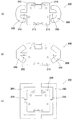
以上本発明の実施形態を説明したが、本発明は上記実施形態に限定されるものではなく、特許請求の範囲、及び明細書と図面に記載された技術的思想の範囲内において種々の変形が可能である。なお直接明細書及び図面に記載がない何れの形状や構造や材質であっても、本願発明の作用・効果を奏する以上、本願発明の技術的思想の範囲内である。例えば、保持台200の取付部260の形状は種々の変更が可能であり、例えば図8(a)に示すように略U字形状に形成しても良いし、図8(b)に示すように略V字形状に形成しても良いし、図8(c)に示すように略コ字形状であって保持台本体部210の周囲を覆う形状に形成しても良い。   Although the embodiments of the present invention have been described above, the present invention is not limited to the above-described embodiments, and various modifications can be made within the scope of the technical idea described in the claims and the specification and drawings. Is possible. Note that any shape, structure, or material not directly described in the specification and drawings is within the scope of the technical idea of the present invention as long as the effects and advantages of the present invention are exhibited. For example, the shape of the mounting portion 260 of the holding base 200 can be variously changed. For example, it may be formed in a substantially U shape as shown in FIG. 8A, or as shown in FIG. May be formed in a substantially V shape, or may be formed in a shape that is substantially U-shaped and covers the periphery of the holding base body 210 as shown in FIG.

また例えば、摺接パターン313の種類を変更することで、電子部品10の出力を抵抗値を変化する出力としても良く、スイッチを切り換える出力としても良い。また上記実施形態では保持台200のヒンジ部250を一対設けたが、場合によっては二対以上設けても良い。また上記実施形態では押圧式スイッチ340を揺動軸Lを挟んだ両側の対向する位置に一対設けたが、2対以上設けても良く、または揺動軸Lの何れか一方の側のみに1つ以上設けても良い。また上記実施形態では保持台200の支持突起223を、基台350上に載置した第2回路基板部330上に対向させたが、第2回路基板部330を設置しないような場合は支持突起223の先端を直接基台350上に対向させても良い。また支持突起223の先端は、第2回路基板部330に(又は直接基台350に)当接するように対向させても良いし、隙間を介して対向させても良い。   Further, for example, by changing the type of the sliding contact pattern 313, the output of the electronic component 10 may be an output that changes the resistance value, or an output that switches a switch. In the above embodiment, a pair of the hinge portions 250 of the holding base 200 are provided, but two or more pairs may be provided depending on circumstances. In the above embodiment, a pair of the push-type switches 340 are provided at opposite positions on both sides of the rocking shaft L. However, two or more pairs may be provided, or only one of the rocking shafts L may be provided on one side. Two or more may be provided. In the above embodiment, the support protrusion 223 of the holding base 200 is opposed to the second circuit board portion 330 placed on the base 350. However, when the second circuit board portion 330 is not installed, the support protrusion 223 is supported. The tip of 223 may be directly opposed to the base 350. Further, the tip of the support protrusion 223 may be opposed so as to contact the second circuit board portion 330 (or directly to the base 350), or may be opposed via a gap.

また電子部品は上記構造の電子部品10に限定されず、他の各種構造の揺動式電子部品,スライド式電子部品であっても良い。要は操作つまみを一定の方向に揺動又は略直線移動することで出力信号を変化させる電子部品であればよい。また上記実施形態では保持台を構成する保持台本体部とヒンジ部と取付部とを一体成形品で構成したが、これら各部を別部品で構成しても良い。例えばヒンジ部を合成樹脂フイルムやゴム材で構成し、このヒンジ部を成形樹脂製の保持台本体部と取付部に固定(熱かしめやインサート成形による)しても良い。   Further, the electronic component is not limited to the electronic component 10 having the above structure, and may be a swinging electronic component or a sliding electronic component having other various structures. In short, any electronic component that changes the output signal by swinging or substantially linearly moving the operation knob in a certain direction may be used. Moreover, in the said embodiment, although the holding stand main-body part which comprises a holding stand, the hinge part, and the attaching part were comprised by the integrally molded product, you may comprise these each part by another component. For example, the hinge portion may be made of a synthetic resin film or rubber material, and the hinge portion may be fixed (by heat caulking or insert molding) to the holding base body portion and the mounting portion made of molded resin.

1 多方向操作型電子部品
10 電子部品
20 操作つまみ
50 第1保持体(保持体)
80 弾発手段
100 移動体
140 摺動子
150 第2保持体(保持体)
200 保持台
223 支持突起
250 ヒンジ部
260 取付部
L 揺動軸
300 フレキシブル回路基板(回路基板)
310 第1回路基板部
330 第2回路基板部
340 押圧式スイッチ
350 基台
DESCRIPTION OF SYMBOLS 1 Multi-directional operation type electronic component 10 Electronic component 20 Operation knob 50 1st holding body (holding body)
80 Bulleting means 100 Moving body 140 Slider 150 Second holding body (holding body)
200 Holding base 223 Supporting protrusion 250 Hinge part 260 Mounting part L Oscillating shaft 300 Flexible circuit board (circuit board)
310 1st circuit board part 330 2nd circuit board part 340 Press type switch 350 Base

Claims (3)

操作つまみを一定の方向に揺動又は略直線移動することで出力信号を変化させる電子部品と、
前記電子部品を載置する保持台本体部と、保持体本体部の外周辺の対向する位置から突出する少なくとも一対の可撓性を有するヒンジ部と、ヒンジ部の先端側部分に取り付けられる取付部とを有し、これによって前記一対のヒンジ部を結ぶ軸を揺動軸として前記保持台本体部を揺動させる保持台と、
前記保持台の前記電子部品を載置した反対面側であって、前記保持台本体部が前記揺動に伴って上下動する位置に配置される押圧式スイッチと、を有し、
前記操作つまみが揺動又は略直線移動する向きと、前記保持台本体部の揺動する向きとが略直交するように前記電子部品を保持台本体部上に設置し、
前記操作つまみを揺動又は略直線移動して電子部品の出力信号を変化させる際は前記保持台本体部が静止し、一方前記操作つまみを前記揺動又は略直線移動方向に対して略直交する方向に揺動する際は前記保持台本体部がその揺動軸を中心に揺動して前記押圧式スイッチを押圧操作することを特徴とする多方向操作型電子部品。
An electronic component that changes the output signal by swinging or substantially linearly moving the operation knob in a certain direction; and
A holding base main body for placing the electronic component, at least a pair of flexible hinges protruding from opposing positions on the outer periphery of the holding main body, and a mounting portion attached to the tip side portion of the hinge A holding base for swinging the holding base body with the axis connecting the pair of hinges as a swing axis,
A pressing switch disposed on the opposite side of the holding base on which the electronic component is placed, and the holding base main body portion is moved up and down with the swinging,
The electronic component is installed on the holding base body so that the direction in which the operation knob swings or moves substantially linearly and the direction in which the holding base body swings are substantially orthogonal,
When changing the output signal of the electronic component by swinging or substantially linearly moving the operation knob, the holding base body portion is stationary, while the operation knob is substantially orthogonal to the swinging or substantially linear movement direction. A multi-directional operation type electronic component in which the holding base main body swings about a swing shaft to press the pressing switch when swinging in a direction.
請求項1に記載の多方向操作型電子部品であって、
前記保持台の取付部と前記押圧式スイッチとを載置する基台をさらに有し、
前記保持台本体部の前記基台を設置した側の面に、先端が前記基台に直接又は他の部材を介して対向して保持台本体部をその揺動方向に揺動自在に支持する支持突起を設けたことを特徴とする多方向操作型電子部品。
The multi-directional operation type electronic component according to claim 1,
And further comprising a base for mounting the mounting portion of the holding base and the pressing switch,
The front end of the holding base main body is opposed to the base on the side where the base is installed, directly or via another member, and supports the holding base main body so as to be swingable in the swing direction. A multi-directional operation type electronic component comprising a support protrusion.
請求項2に記載の多方向操作型電子部品であって、
前記押圧式スイッチは、前記揺動軸を挟んだ両側の対向する位置に一対設けられていることを特徴とする多方向操作型電子部品。
The multidirectional operation type electronic component according to claim 2,
A multi-directional operation type electronic component, wherein a pair of the pressing switches are provided at opposing positions on both sides of the swing shaft.
JP2011255120A 2011-11-22 2011-11-22 Multi-directional electronic components Expired - Fee Related JP5766101B2 (en)

Priority Applications (1)

Application Number Priority Date Filing Date Title
JP2011255120A JP5766101B2 (en) 2011-11-22 2011-11-22 Multi-directional electronic components

Applications Claiming Priority (1)

Application Number Priority Date Filing Date Title
JP2011255120A JP5766101B2 (en) 2011-11-22 2011-11-22 Multi-directional electronic components

Publications (2)

Publication Number Publication Date
JP2013110012A true JP2013110012A (en) 2013-06-06
JP5766101B2 JP5766101B2 (en) 2015-08-19

Family

ID=48706562

Family Applications (1)

Application Number Title Priority Date Filing Date
JP2011255120A Expired - Fee Related JP5766101B2 (en) 2011-11-22 2011-11-22 Multi-directional electronic components

Country Status (1)

Country Link
JP (1) JP5766101B2 (en)

Citations (2)

* Cited by examiner, † Cited by third party
Publication number Priority date Publication date Assignee Title
JPS60112037U (en) * 1983-12-29 1985-07-29 クラリオン株式会社 Button switch mechanism
JP2011034796A (en) * 2009-07-31 2011-02-17 Alps Electric Co Ltd Input control device

Patent Citations (2)

* Cited by examiner, † Cited by third party
Publication number Priority date Publication date Assignee Title
JPS60112037U (en) * 1983-12-29 1985-07-29 クラリオン株式会社 Button switch mechanism
JP2011034796A (en) * 2009-07-31 2011-02-17 Alps Electric Co Ltd Input control device

Also Published As

Publication number Publication date
JP5766101B2 (en) 2015-08-19

Similar Documents

Publication Publication Date Title
JP2004171924A (en) Multi-directional slide switch
JP5766101B2 (en) Multi-directional electronic components
JP2000260264A (en) Combined control type electric component
JP2008305687A (en) Multidirectional operation switch
JP6813752B2 (en) Rotary electronic components with press switch
US20080041706A1 (en) Operating button device
JP4334576B2 (en) Two-stage push switch and push switch with rotating electronic components
JP4247312B2 (en) Electronics
JP6643137B2 (en) Rotary electronic components with click mechanism
JP5722738B2 (en) Multifunctional electronic components
JP3931528B2 (en) Press / rotation operation type electronic components and electronic equipment using the same
JP6549979B2 (en) Rotary electronic parts with pressure switch
JP4013442B2 (en) Pressing / rotating operation type electronic component and its mounting method
JP5323669B2 (en) Electronic parts with click function
JP4846662B2 (en) Multi-directional operation switch
JP4601718B2 (en) Multifunctional electronic components
JP7033785B2 (en) Switch mechanism
JP2005019314A (en) Multi-directional push switch
JP2008282700A (en) Electronic components
JP2007335191A (en) Multifunctional electronic components
JP2007141501A (en) Electronic component locking mechanism
JP4619196B2 (en) Sliding electronic parts with pressure switch
JP3920567B2 (en) Composite operation type electric parts
JP2005293885A (en) Operation panel for electronic parts
JP2007053018A (en) Sliding electronic component and its assembly method

Legal Events

Date Code Title Description
A621 Written request for application examination

Free format text: JAPANESE INTERMEDIATE CODE: A621

Effective date: 20140227

A977 Report on retrieval

Free format text: JAPANESE INTERMEDIATE CODE: A971007

Effective date: 20141112

A131 Notification of reasons for refusal

Free format text: JAPANESE INTERMEDIATE CODE: A131

Effective date: 20141118

A521 Request for written amendment filed

Free format text: JAPANESE INTERMEDIATE CODE: A523

Effective date: 20150115

TRDD Decision of grant or rejection written
A01 Written decision to grant a patent or to grant a registration (utility model)

Free format text: JAPANESE INTERMEDIATE CODE: A01

Effective date: 20150609

A61 First payment of annual fees (during grant procedure)

Free format text: JAPANESE INTERMEDIATE CODE: A61

Effective date: 20150616

R150 Certificate of patent or registration of utility model

Ref document number: 5766101

Country of ref document: JP

Free format text: JAPANESE INTERMEDIATE CODE: R150

R250 Receipt of annual fees

Free format text: JAPANESE INTERMEDIATE CODE: R250

R250 Receipt of annual fees

Free format text: JAPANESE INTERMEDIATE CODE: R250

R250 Receipt of annual fees

Free format text: JAPANESE INTERMEDIATE CODE: R250

R250 Receipt of annual fees

Free format text: JAPANESE INTERMEDIATE CODE: R250

R250 Receipt of annual fees

Free format text: JAPANESE INTERMEDIATE CODE: R250

LAPS Cancellation because of no payment of annual fees