JP2013103761A - Rotary-type bag filling and packaging machine - Google Patents
Rotary-type bag filling and packaging machine Download PDFInfo
- Publication number
- JP2013103761A JP2013103761A JP2011251173A JP2011251173A JP2013103761A JP 2013103761 A JP2013103761 A JP 2013103761A JP 2011251173 A JP2011251173 A JP 2011251173A JP 2011251173 A JP2011251173 A JP 2011251173A JP 2013103761 A JP2013103761 A JP 2013103761A
- Authority
- JP
- Japan
- Prior art keywords
- bag
- rotary
- packaging
- packaging processing
- packaging machine
- Prior art date
- Legal status (The legal status is an assumption and is not a legal conclusion. Google has not performed a legal analysis and makes no representation as to the accuracy of the status listed.)
- Granted
Links
- 238000004806 packaging method and process Methods 0.000 title claims abstract description 106
- 238000007664 blowing Methods 0.000 claims description 50
- 230000001360 synchronised effect Effects 0.000 claims description 31
- 239000007788 liquid Substances 0.000 claims description 21
- 238000001514 detection method Methods 0.000 claims description 20
- 238000007789 sealing Methods 0.000 claims description 4
- 238000002347 injection Methods 0.000 abstract description 10
- 239000007924 injection Substances 0.000 abstract description 10
- 230000003028 elevating effect Effects 0.000 abstract description 9
- 239000000243 solution Substances 0.000 abstract 1
- 238000009434 installation Methods 0.000 description 16
- 238000012858 packaging process Methods 0.000 description 7
- 230000000630 rising effect Effects 0.000 description 6
- 230000001174 ascending effect Effects 0.000 description 4
- 238000001816 cooling Methods 0.000 description 3
- 238000003780 insertion Methods 0.000 description 3
- 230000037431 insertion Effects 0.000 description 3
- 238000007689 inspection Methods 0.000 description 3
- 230000001788 irregular Effects 0.000 description 3
- 230000007423 decrease Effects 0.000 description 2
- 238000005187 foaming Methods 0.000 description 2
- 230000007246 mechanism Effects 0.000 description 2
- 238000000034 method Methods 0.000 description 2
- 238000006073 displacement reaction Methods 0.000 description 1
- 238000004519 manufacturing process Methods 0.000 description 1
- 230000000149 penetrating effect Effects 0.000 description 1
- 238000006467 substitution reaction Methods 0.000 description 1
Images


Classifications
-
- B—PERFORMING OPERATIONS; TRANSPORTING
- B65—CONVEYING; PACKING; STORING; HANDLING THIN OR FILAMENTARY MATERIAL
- B65B—MACHINES, APPARATUS OR DEVICES FOR, OR METHODS OF, PACKAGING ARTICLES OR MATERIALS; UNPACKING
- B65B1/00—Packaging fluent solid material, e.g. powders, granular or loose fibrous material, loose masses of small articles, in individual containers or receptacles, e.g. bags, sacks, boxes, cartons, cans, or jars
- B65B1/04—Methods of, or means for, filling the material into the containers or receptacles
-
- B—PERFORMING OPERATIONS; TRANSPORTING
- B65—CONVEYING; PACKING; STORING; HANDLING THIN OR FILAMENTARY MATERIAL
- B65B—MACHINES, APPARATUS OR DEVICES FOR, OR METHODS OF, PACKAGING ARTICLES OR MATERIALS; UNPACKING
- B65B3/00—Packaging plastic material, semiliquids, liquids or mixed solids and liquids, in individual containers or receptacles, e.g. bags, sacks, boxes, cartons, cans, or jars
- B65B3/04—Methods of, or means for, filling the material into the containers or receptacles
-
- B—PERFORMING OPERATIONS; TRANSPORTING
- B65—CONVEYING; PACKING; STORING; HANDLING THIN OR FILAMENTARY MATERIAL
- B65B—MACHINES, APPARATUS OR DEVICES FOR, OR METHODS OF, PACKAGING ARTICLES OR MATERIALS; UNPACKING
- B65B31/00—Packaging articles or materials under special atmospheric or gaseous conditions; Adding propellants to aerosol containers
- B65B31/04—Evacuating, pressurising or gasifying filled containers or wrappers by means of nozzles through which air or other gas, e.g. an inert gas, is withdrawn or supplied
- B65B31/041—Evacuating, pressurising or gasifying filled containers or wrappers by means of nozzles through which air or other gas, e.g. an inert gas, is withdrawn or supplied the nozzles acting from above on containers or wrappers open at their top
- B65B31/042—Evacuating, pressurising or gasifying filled containers or wrappers by means of nozzles through which air or other gas, e.g. an inert gas, is withdrawn or supplied the nozzles acting from above on containers or wrappers open at their top the nozzles being arranged for insertion into, and withdrawal from, the container or wrapper
-
- B—PERFORMING OPERATIONS; TRANSPORTING
- B65—CONVEYING; PACKING; STORING; HANDLING THIN OR FILAMENTARY MATERIAL
- B65B—MACHINES, APPARATUS OR DEVICES FOR, OR METHODS OF, PACKAGING ARTICLES OR MATERIALS; UNPACKING
- B65B39/00—Nozzles, funnels or guides for introducing articles or materials into containers or wrappers
- B65B39/12—Nozzles, funnels or guides for introducing articles or materials into containers or wrappers movable towards or away from container or wrapper during filling or depositing
-
- B—PERFORMING OPERATIONS; TRANSPORTING
- B65—CONVEYING; PACKING; STORING; HANDLING THIN OR FILAMENTARY MATERIAL
- B65B—MACHINES, APPARATUS OR DEVICES FOR, OR METHODS OF, PACKAGING ARTICLES OR MATERIALS; UNPACKING
- B65B39/00—Nozzles, funnels or guides for introducing articles or materials into containers or wrappers
- B65B39/14—Nozzles, funnels or guides for introducing articles or materials into containers or wrappers movable with a moving container or wrapper during filling or depositing
-
- B—PERFORMING OPERATIONS; TRANSPORTING
- B65—CONVEYING; PACKING; STORING; HANDLING THIN OR FILAMENTARY MATERIAL
- B65B—MACHINES, APPARATUS OR DEVICES FOR, OR METHODS OF, PACKAGING ARTICLES OR MATERIALS; UNPACKING
- B65B43/00—Forming, feeding, opening or setting-up containers or receptacles in association with packaging
- B65B43/26—Opening or distending bags; Opening, erecting, or setting-up boxes, cartons, or carton blanks
-
- B—PERFORMING OPERATIONS; TRANSPORTING
- B65—CONVEYING; PACKING; STORING; HANDLING THIN OR FILAMENTARY MATERIAL
- B65B—MACHINES, APPARATUS OR DEVICES FOR, OR METHODS OF, PACKAGING ARTICLES OR MATERIALS; UNPACKING
- B65B43/00—Forming, feeding, opening or setting-up containers or receptacles in association with packaging
- B65B43/42—Feeding or positioning bags, boxes, or cartons in the distended, opened, or set-up state; Feeding preformed rigid containers, e.g. tins, capsules, glass tubes, glasses, to the packaging position; Locating containers or receptacles at the filling position; Supporting containers or receptacles during the filling operation
- B65B43/50—Feeding or positioning bags, boxes, or cartons in the distended, opened, or set-up state; Feeding preformed rigid containers, e.g. tins, capsules, glass tubes, glasses, to the packaging position; Locating containers or receptacles at the filling position; Supporting containers or receptacles during the filling operation using rotary tables or turrets
-
- B—PERFORMING OPERATIONS; TRANSPORTING
- B65—CONVEYING; PACKING; STORING; HANDLING THIN OR FILAMENTARY MATERIAL
- B65B—MACHINES, APPARATUS OR DEVICES FOR, OR METHODS OF, PACKAGING ARTICLES OR MATERIALS; UNPACKING
- B65B57/00—Automatic control, checking, warning, or safety devices
Abstract
Description
本発明は、供給された袋の両側縁部を挟持して袋を吊り下げ保持するグリッパー対を、水平面内で一方向に連続回転又は間欠回転する回転テーブルの周囲に複数対等間隔に備え、前記グリッパー対を連続的又は前記間隔毎に間欠的に一方向に回転移動させ、前記グリッパー対で保持した袋に対し、袋口の開口、被包装物の充填及び袋口のシール等の各種包装処理操作を順次施すロータリー型袋詰め包装機の改良に関する。 The present invention comprises a plurality of gripper pairs that sandwich and hold both side edges of the supplied bag to suspend and hold the bag at a plurality of equal intervals around a rotary table that rotates continuously or intermittently in one direction in a horizontal plane, Various types of packaging processes such as opening the bag mouth, filling the package, and sealing the bag mouth with respect to the bag held by the gripper pair by rotating the gripper pair in one direction intermittently or intermittently at each interval. The present invention relates to an improvement of a rotary type bag filling and packaging machine that sequentially performs operations.
前記各種包装処理操作を行う包装処理装置には、同調式包装処理装置として知られるタイプのものがある。この同調式包装処理装置は複数の包装処理部材を含み、前記包装処理部材は各グリッパー対に対応して設置され、各グリッパー対と同調して回転移動しながら所定のタイミングで昇降する。
例えば特許文献1に記載されたロータリー型袋詰め包装機は、複数の充填漏斗を包装処理部材として含む同調式包装処理装置を備える。各充填漏斗は各グリッパー対に対応して設置され、各グリッパー対とともに回転移動しながら所定のタイミングで昇降する。
特許文献2に記載されたロータリー型袋詰め包装機は、複数の充填漏斗を包装処理部材として含む同調式包装処理装置と、複数のガス吹込ノズルを包装処理部材として含むもう1つの同調式包装処理装置を備える。各充填漏斗は各グリッパー対に対応して設置され、各ガス充填ノズルは各充填漏斗に設置され、いずれも各グリッパー対と共に回転移動しながら所定のタイミングで昇降する。
Among the packaging processing devices that perform the various packaging processing operations, there is a type known as a synchronous packaging processing device. This synchronous packaging processing apparatus includes a plurality of packaging processing members, and the packaging processing members are installed corresponding to each pair of grippers, and move up and down at a predetermined timing while rotating in synchronization with each pair of grippers.
For example, a rotary type bag filling and packaging machine described in
The rotary type bag filling and packaging machine described in
特許文献3に記載されたロータリー型袋詰め包装機は、複数のガス吹込ノズル又は液状物充填ノズルを包装処理部材として含む同調式包装処理装置を備える。各ノズルは各グリッパー対に対応して設置され、各グリッパー対と共に回転移動しながら所定のタイミングで昇降する。
特許文献4に記載されたロータリー型袋詰め包装機は、複数対の開口ガイド部材(ガス吹込ノズル兼用)を包装処理部材として含む同調式包装処理装置を備える。各開口ガイド部材の対は各グリッパー対に対応して設置され、各グリッパー対と共に回転移動しながら所定のタイミングで昇降及び開閉する。
特許文献5はロータリー型袋詰め包装機に関するものではなく、容器のキャッピング装置であるが、複数の栓把持機構が容器把持機構と共に回転移動しながら所定のタイミングで昇降する。
The rotary type bag filling and packaging machine described in
The rotary type bag filling and packaging machine described in
Patent Document 5 is not related to a rotary-type bag filling and packaging machine, but is a container capping device, and a plurality of stopper gripping mechanisms move up and down at a predetermined timing while rotating together with the container gripping mechanism.
上記ロータリー型袋詰め包装機において、常に単一の包装製品(袋サイズ、袋形状、被包装物が同一のもの)を製造する場合と、必要に応じて複数種類の包装製品を製造したいという場合があり得る。後者の場合、製造する包装製品を変更するに際し、同時に包装処理部材の設置位置及び昇降動作を当該包装製品に適する仕様に変更することが望ましい場合がある。
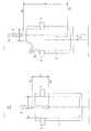
この点について、図4(a),(b)の例(同調式包装処理装置の包装処理部材が液体充填ノズルの場合)を参照して説明する。充填の対象とする袋は、図4(a)では通常の四角形の平袋1であり、図4(b)では上部の角部に注出口2aが形成された異形の平袋2(以下、異形袋2という)であり、両者の袋幅及び袋長さは同一である。なお、図4(a),(b)に示す液体充填ノズル4の設置位置及び昇降高さは、各袋形状に適する仕様と仮定する。
In the above-mentioned rotary type bag filling and packaging machine, when always producing a single packaged product (the same bag size, bag shape and packaged items) and when you want to produce multiple types of packaged products as needed There can be. In the latter case, when changing the packaged product to be manufactured, it may be desirable to simultaneously change the installation position of the packaging processing member and the lifting operation to specifications suitable for the packaged product.
This point will be described with reference to the examples of FIGS. 4A and 4B (when the packaging processing member of the synchronous packaging processing apparatus is a liquid filling nozzle). The bag to be filled is a normal rectangular
図4(a)では、液体充填ノズル4の設置位置は、グリッパー対3,3に把持された平袋1の袋口の袋幅方向の中心位置Mc(一点鎖線で示す)に設定される。この中心位置Mcは、グリッパー対3,3の中心位置Gc(平袋1の袋幅方向の中心位置でもある)と一致する。また、液体充填ノズル4の昇降範囲Hは、上昇端位置Huと下降端位置Hdの間に設定される。
図4(b)では、液体充填ノズル4の設置位置は、グリッパー対3,3に把持された異形袋2の袋口の袋幅方向の中心位置Mcに設定されるが、この中心位置Mcは、グリッパー対3,3の中心位置Gc(異形袋2の袋幅方向の中心位置でもある)とは、距離Wだけ周方向に沿ってずれている。また、異形袋2の場合、グリッパー対3,3による把持位置が平袋1に比べてやや下の位置になるので、液体充填ノズル4の上昇端位置Huは、平袋1の場合の上昇端位置Huより高く設定され、さらに、液体充填ノズル4の下降端位置Hdは、液体充填時の泡立ちや液撥ねを防止するため、異形袋2の袋底付近に設定され、昇降範囲Hは、平袋1の場合の昇降範囲Hと異なる。
In FIG. 4A, the installation position of the
In FIG. 4B, the installation position of the
このロータリー型袋詰め包装機において、充填の対象とする袋がこれまで平袋1であったところ、これを異形袋2に変更する場合、同調式包装処理装置の包装処理部材である各液体充填ノズル4の設置位置及び昇降範囲を、図4(b)に示すように変更することが望ましい。
しかし、液体充填ノズル4は複数個(グリッパー対3,3と同じ数)存在することから、全ての液体充填ノズル4について周方向に沿って設置位置を変更する作業は極めて複雑で面倒であり、生産性の低下は免れない。これは、図4に示す液体充填ノズル4だけでなく、例えばガス吹込ノズルや充填漏斗など(特許文献1〜4参照)、全ての同調式包装処理装置の包装処理部材に共通する問題点である。
In this rotary type bag filling and packaging machine, when the bag to be filled is the
However, since there are a plurality of liquid filling nozzles 4 (the same number as the gripper pairs 3 and 3), the operation of changing the installation positions along the circumferential direction for all the
また、従来の同調式包装処理装置の包装処理部材はいずれもカムを駆動源として昇降する構造であり、このカムは包装機の機体に一体に組み込まれている(特許文献1〜4参照)。このため、包装処理部材の昇降動作(昇降範囲のほか、昇降タイミング、昇降速度、1回の充填における昇降回数等も含む)を変更することは実質的に困難である。仮に包装処理部材を昇降させる駆動源をエアシリンダに代えたとしても(特許文献5参照)、昇降範囲や昇降速度を変更すること等は実質的に困難である。
Moreover, all the packaging processing members of the conventional synchronous packaging processing apparatus have a structure that moves up and down using a cam as a drive source, and this cam is integrated into the body of the packaging machine (see
本発明は、同調式包装処理装置を備えた従来のロータリー型袋詰め包装機に関する上記問題点に鑑みてなされたもので、前記同調式包装処理装置の包装処理部材の設置位置及び昇降動作を、対象とする包装製品に適する仕様に変更することが容易になし得るようにすることを目的とする。 The present invention has been made in view of the above-mentioned problems related to a conventional rotary type bag filling and packaging machine equipped with a synchronous packaging processing apparatus, and the installation position and elevation operation of the packaging processing member of the synchronous packaging processing apparatus are as follows. It is intended to make it easy to change the specification suitable for the target packaged product.
本発明は、供給された袋の両側縁部を挟持して袋を吊り下げ保持するグリッパー対を、水平面内で一方向に連続回転又は間欠回転する回転テーブルの周囲に複数対等間隔に備え、前記グリッパー対を連続的又は前記間隔毎に間欠的に一方向に回転移動させ、前記グリッパー対で保持した袋に対し、袋口の開口、被包装物の充填及び袋口のシール等の各種包装処理操作を順次施すロータリー型袋詰め包装機、特に、同調式包装処理装置が設置されたロータリー型袋詰め包装機を改良したもので、前記回転テーブルの上方位置に配置され、前記回転テーブルと同じ軸線を有し、前記同調式包装処理装置の包装処理部材が周囲に複数等間隔で設置された同調テーブルと、前記同調テーブルを回転させる第1サーボモータと、各包装処理部材に対応して前記同調テーブルに設置され、前記包装処理部材を昇降させる第2サーボモータと、前記回転テーブルの駆動源と前記第1,第2サーボモータの駆動を制御して、前記同調テーブルを前記回転テーブルに同調して回転させ、かつ前記包装処理部材を所定のタイミングで昇降させる制御装置を備えることを特徴とする。 The present invention comprises a plurality of gripper pairs that sandwich and hold both side edges of the supplied bag to suspend and hold the bag at a plurality of equal intervals around a rotary table that rotates continuously or intermittently in one direction in a horizontal plane, Various types of packaging processes such as opening the bag mouth, filling the package, and sealing the bag mouth with respect to the bag held by the gripper pair by rotating the gripper pair in one direction intermittently or intermittently at each interval. A rotary type bagging and packaging machine that performs operations sequentially, in particular, an improvement of a rotary type bagging and packaging machine in which a synchronous packaging processing device is installed, and is arranged above the rotary table and has the same axis as the rotary table. Corresponding to each of the packaging processing members, a tuning table in which a plurality of packaging processing members of the synchronous packaging processing device are installed at equal intervals around the first servo motor for rotating the tuning table, and A second servo motor that is installed on the tuning table and moves the packaging processing member up and down, a drive source of the rotary table, and a drive of the first and second servo motors are controlled to make the tuning table into the rotary table. A control device is provided that rotates synchronously and moves the packaging processing member up and down at a predetermined timing.
上記ロータリー型袋詰め包装機は、例えば次のような好ましい形態を取り得る。
(1)前記回転テーブルの定位置と前記同調テーブルの定位置の回転方向の相対位置関係を検出するセンサーが設置され、前記制御装置は、前記センサーの検出信号に基づき、前記両定位置の回転方向の相対位置関係を調整する。
(2)前記回転テーブルの定位置と前記同調テーブルの定位置の回転方向の相対位置関係を検出するセンサーが設置され、包装製品の種類とそれに対応する両定位置の回転方向の相対位置関係のデータが前記制御装置に予め入力されており、前記制御装置は、前記センサーの検出信号と前記データに基づき、包装製品の種類に応じて前記両定位置の回転方向の相対位置関係を調整する。
(3)前記包装処理部材がガス吹込ノズル又は液体充填ノズルである。
(4)回転テーブルが間欠回転する。
The rotary type bag filling and packaging machine can take the following preferable forms, for example.
(1) A sensor for detecting a relative positional relationship between the fixed position of the rotary table and the fixed position of the tuning table in the rotation direction is installed, and the control device rotates the fixed positions based on the detection signal of the sensor. Adjust the relative positional relationship of directions.
(2) A sensor for detecting the relative positional relationship between the fixed position of the rotary table and the fixed position of the tuning table in the rotational direction is installed. Data is input to the control device in advance, and the control device adjusts the relative positional relationship in the rotational direction of the two fixed positions according to the type of the packaged product based on the detection signal of the sensor and the data.
(3) The packaging processing member is a gas blowing nozzle or a liquid filling nozzle.
(4) The rotary table rotates intermittently.
本発明によれば、制御装置により第1,第2サーボモータを駆動制御することにより、同調式包装処理装置の全ての包装処理部材を、グリッパー対に同調(同期)して回転移動させることができるだけでなく、前記包装処理部材のグリッパー対に対する周方向の設置位置、及び前記包装処理部材の昇降動作の仕様を、包装製品の種類(各種の袋サイズ、袋形状、被包装物など)に応じて自在に設定できるようになる。 According to the present invention, by driving and controlling the first and second servo motors by the control device, all the packaging processing members of the synchronous packaging processing device can be rotated and moved in synchronization (synchronization) with the gripper pair. Not only can the installation position of the packaging processing member in the circumferential direction with respect to the gripper pair, and the specifications of the lifting and lowering operation of the packaging processing member, depending on the type of packaging product (various bag sizes, bag shapes, packages, etc.) Can be set freely.
従って、同調式包装処理装置の包装処理部材が例えば液体充填ノズルであれば、昇降動作の仕様変更ができない場合に比べて、液体充填時の泡立ちや液撥ねを防止することができ、例えばガス充填ノズルであればガス置換率や脱気率を改善することができ、これにより完成度の高い包装製品を得ることができる。
また、同調式包装処理装置の全ての包装処理部材のグリッパー対に対する周方向の設置位置を容易に変更することができるので、例えば図4(b)に示す異形袋2のように、袋口の袋幅方向の中心位置Mcとグリッパー対の中心位置Gcがずれている場合に、同調式包装処理装置に含まれる全ての液体充填ノズルやガス充填ノズル等の設置位置を,例えば前記中心位置Mcに一致させることが、生産性の低下を招くことなく実施できる。
Therefore, if the packaging processing member of the synchronous packaging processing apparatus is, for example, a liquid filling nozzle, it is possible to prevent foaming and liquid splashing during liquid filling compared to the case where the specification of the lifting operation cannot be changed. If it is a nozzle, a gas substitution rate and a deaeration rate can be improved, and, thereby, a highly complete packaged product can be obtained.
Moreover, since the installation position of the circumferential direction with respect to the gripper pair of all the packaging processing members of the synchronous packaging processing apparatus can be easily changed, for example, like the
以下、図1〜図4を参照して、本発明に係るロータリー型袋詰め包装機について、具体的に説明する。
図1,2に示すロータリー型袋詰め包装機は、間欠回転式のロータリー型袋移送装置11と、同調式包装処理装置12(以下、同調式ガス置換装置12という)を含む複数の包装処理装置と、制御装置13及び位置検出センサ14等を備える。
ロータリー型袋移送装置11は、機台15上に設置され、図示しない駆動源により水平面内で一方向(図1において反時計回り)に間欠回転する回転テーブル16と、その周囲に等間隔に配置された10組のグリッパー対3,3を有する。グリッパー対3,3は、回転テーブル16の間欠回転に伴い、水平面内の円形の移動経路上を等角度間隔で間欠移動(間欠回転)し、その間欠移動の間、周知の如く所定のタイミングでグリッパー対3,3の挟持部3a,3aが開閉し、かつ該挟持部3a,3aの間隔が広がり又は狭まる。
Hereinafter, the rotary type bag filling and packaging machine according to the present invention will be specifically described with reference to FIGS.
The rotary type bag filling and packaging machine shown in FIGS. 1 and 2 includes a plurality of packaging processing apparatuses including an intermittent rotation type rotary type bag transfer device 11 and a synchronous packaging processing device 12 (hereinafter referred to as a synchronous gas replacement device 12). And a
The rotary type bag transfer device 11 is installed on the
同調式ガス置換装置12は、機台15上に設置されたフレーム18、フレーム18に水平回転自在に支持された同調テーブル19、同調テーブル19を回転させる第1サーボモータ21、同調テーブル19の周囲に等間隔で設置された10個のガス吹込ユニット22等からなる。各ガス吹込ユニット22は、同調テーブル19上に設置された支持スタンド23、支持スタンド23に鉛直かつ回転自在に支持されたねじ軸24、同調テーブル19上に設置されねじ軸24を回転させる第2サーボモータ25、同調テーブル19上に立設し上端が支持スタンド23に固定されたスライド軸26、スライド軸26が貫通しスライド軸26に沿って上下にスライド自在なスライド部材27、スライド部材27の外側突出片27aに固定されたガス吹込ノズル28等からなる。スライド部材27の内側突出片27bがねじ軸24に螺合し、第2サーボモータ25が作動することで、スライド部材27及びガス吹込ノズル28が昇降する。
The tuned
同調テーブル19は回転テーブル16と同じ軸線(回転の中心となる線)を有する。同調テーブル19を回転させる第1サーボモータ21は、回転テーブル16の駆動源とは独立した駆動源である。10個のガス吹込ノズル28は、同調テーブル19の周囲に等間隔に配置され、同調テーブル19の回転に伴い、平面視でグリッパー対3,3の移動経路とほぼ重なる移動経路に沿って回転する。ガス吹込ノズル28はそれぞれ配管29を通して、図示しない切換弁(ロータリーバルブ)及びガス供給源に接続している。
The tuning table 19 has the same axis (the line that becomes the center of rotation) as the rotary table 16. The
ロータリー型袋移送装置11の回転テーブル16は、一回転する間に等角度間隔で10回停止し、回転テーブル16の周囲の各グリッパー対3,3の停止位置(A〜J)には、同調式包装処理装置12以外の包装処理装置が配置されている。図1に示すように、停止位置Aにコンベアマガジン式給袋装置31、停止位置Bに印字装置32、停止位置Cに印字検査装置33、停止位置Dに袋口の開口装置(吸盤対34,34のみ示す)、停止位置Eに被包装物供給装置(ホッパー35のみ示す)、停止位置Iに一対の熱板の36a,36aを備えたシール装置36、停止位置Jに一対の冷却板37a,37aを備えたシール部冷却装置37と包装製品排出シュート38が配置されている。
なお、ホッパー35は縦に2分割された2つのホッパー片35a,35aがヒンジを介して連結したもので、実線で示すように筒形に閉じ、又は2点鎖線で示すように開く。また、ホッパー35は、実線で示す前進位置と2点鎖線で示す退避位置の間を開いた状態で進退し、かつ前進位置において閉じ、昇降する。ホッパー35の上記開閉構造及び移動形態により、ホッパー35とガス吹込ノズル28の相互の干渉が防止される。
The rotary table 16 of the rotary type bag transfer device 11 stops 10 times at equal angular intervals during one rotation, and is synchronized with the stop positions (A to J) of the gripper pairs 3 and 3 around the rotary table 16. A packaging processing apparatus other than the type
The
位置検出センサ14は近接センサであり、同調テーブル19の下面の所定位置に設置され、回転テーブル16の上面に設置された検出片39を検出する。位置検出センサ14は、回転テーブル16と同調テーブル19の相対位置関係を調整するためのものである。
このロータリー型袋詰め包装機では、各ガス吹込ノズル28が、各グリッパー対3,3の中心位置Gc(図4(a)参照)の直上に位置したとき、ちょうど位置検出センサ14が検出片39を検出するように、位置検出センサ14と検出片39の設置位置が決められている。なお、各グリッパー対3,3の中心位置Gcは、平袋1の袋口の袋幅方向の中心位置Mcでもある。
位置検出センサ14が検出片39を検出し、その検出信号が制御装置13に送られることで、制御装置13は回転テーブル16における前記中心位置Gcと、同調テーブル19におけるガス吹込ノズル28の設置位置のずれ(ずれの有無、ずれの大きさ)、すなわち回転テーブル16と同調テーブル19の相対位置関係を知ることができる。
The
In this rotary type bag filling and packaging machine, when each
When the
回転テーブル16は、制御装置13に制御される図示しない駆動源により、各グリッパー対3,3の中心位置Gcが常に同じ位置(停止位置A〜J)に停止するように、間欠的に回転する。この停止位置は包装製品が変わっても基本的に変更されることはない。
同調テーブル19は、同じく制御装置13に制御される第1サーボモータ21により、回転テーブル16に同調(同期)して、間欠的に回転する。回転テーブル16と同調テーブル19の相対位置関係は、同じ包装製品を取り扱う限り基本的に一定に保たれるが、包装製品の種類(袋のサイズ、袋の種類、被包装物の種類等)が変わると、前記相対位置関係が変更されることがある。具体的には、図4を参照して説明したとおり、充填に使用する袋が平袋1の場合、回転テーブル16と同調テーブル19の相対位置関係は、前記中心位置Gcとガス吹込ノズル28の設置位置がちょうど重なるように設定される。これに対し、充填に使用する袋が異形袋2の場合、回転テーブル16と同調テーブル19の相対位置関係は、前記中心位置Gcとガス吹込ノズル28の設置位置が距離Wだけずれるように設定される。
The
The tuning table 19 is intermittently rotated in synchronization (synchronization) with the rotary table 16 by the
一方、制御装置13の記憶手段には、複数の包装製品に対応する前記相対位置関係のデータ(回転テーブル16におけるグリッパー対3,3の中心位置Gcと同調テーブル19におけるガス吹込ノズル28の設置位置のずれの距離)が予め入力されている。この相対位置関係のデータは、回転テーブル16と同調テーブル19が停止し、かつ位置検出センサ14が検出片39を検出した時点を原点位置とし、そこから第1サーボモータ21のみが作動してガス吹込ノズル28が所定距離移動するまでに、前記第1サーボモータ21のシャフトに直結したエンコーダが発生するパルス数で表すことができる。このパルス数は、充填に使用する袋が平袋1の場合はゼロであり、異形袋2の場合は距離Wに相当するパルス数である。なお、図2の例では、前記原点位置において、グリッパー対3,3の中心位置Gcとガス吹込ノズル28の設置位置が平面視でちょうど重なる。
また、制御装置13の記憶手段には、複数の包装製品に対応するガス吹込ノズル28の昇降動作(昇降範囲、昇降タイミング、昇降速度、1回の吹込における昇降回数等)の仕様、及びガス吹き込みの開始及び停止のタイミング等が予め入力されている。
On the other hand, the storage means of the
In addition, in the storage means of the
次に図1,2に示すロータリー型袋詰め包装機の、特に回転テーブル16及び同調テーブル19の作動について説明する。
包装処理の開始に先立ち、制御装置13の図示しない制御盤を操作して,包装製品の種類に応じた初期設定を行う(具体的には制御盤から包装製品の種類を入力するのみ)。すると、回転テーブル16が駆動源の作動により前記原点位置に位置決めされ、同時に同調テーブル19が第1サーボモータ21の作動により、位置検出センサ14の検出信号に基づき前記原点位置に位置決めされる。さらに第1サーボモータ21が継続して作動し、包装製品の種類に対応する所定のパルス数だけ同調テーブル19を回転させる。
Next, the operation of the rotary table 16 and the tuning table 19 of the rotary type bag filling and packaging machine shown in FIGS.
Prior to the start of the packaging process, a control panel (not shown) of the
入力した包装製品の袋形状が平袋1の場合、包装製品の種類に対応する所定のパルス数はゼロであり、同調テーブル19の前記原点位置からの回転はなく、上記原点位置が同調テーブル19の間欠回転の基準位置となる。このとき、ガス吹込ノズル28の設置位置は、グリッパー対3,3の中心位置Gcと平面視で重なる。
続いて、制御装置13の制御盤を操作して包装処理を開始すると、回転テーブル16は、各グリッパー対3,3の中心位置Gcが常に同じ位置(停止位置A〜J)に停止するように間欠的に回転し、同調テーブル19は回転テーブル16に同調(同期)して間欠的に回転し、その間、回転テーブル16との相対位置関係は一定に保たれる。従って、グリッパー対3,3と対応するガス吹込ノズル28の相対位置関係も一定に保たれる。また、ガス吹込ノズル28は、第2サーボモータ21の作動により、入力した包装製品の種類に対応する昇降動作を行う。
When the bag shape of the input packaged product is a
Subsequently, when the packaging process is started by operating the control panel of the
一方、入力した包装製品の袋形状が異形袋2の場合、同調テーブル19は前記原点位置から図4(b)に示す距離Wに相当するパルス数だけ回転して停止し、各ガス吹込ノズル28は平面視で距離Wだけ各グリッパー対3,3の中心位置Gcから離れた位置に停止する。この位置が同調テーブル19の間欠回転の基準位置となる(図3参照)。
続いて、制御装置13の制御盤を操作して包装処理を開始すると、回転テーブル16は、各グリッパー対3,3の中心位置Gcが常に同じ位置(停止位置A〜J)に停止するように間欠的に回転し、同調テーブル19は回転テーブル16に同調(同期)して間欠的に回転し、その間、回転テーブル16との相対位置関係は一定に保たれる。従って、グリッパー対3,3と対応するガス吹込ノズル28の相対位置関係も一定に保たれる。また、ガス吹込ノズル28は、第2サーボモータ21の作動により、入力した包装製品の種類に対応する昇降動作を行う。
On the other hand, when the bag shape of the input packaged product is the
Subsequently, when the packaging process is started by operating the control panel of the
次に、図1,2に示すロータリー型袋詰め包装機による包装処理工程全体について説明する。
まず、停止位置Aでは、停止したグリッパー対3,3に対しコンベアマガジン式給袋装置31から平袋1が供給され、停止位置Bでは、平袋1の袋面に印字装置32により印字が行われ、停止位置Cでは、印字検査装置33により袋面の印字検査が行われる。
停止位置Dでは、平袋1の袋口が開口装置の吸盤対34,34により開口され(このときグリッパー対3,3の間隔が狭まる)、次いでそれまで上昇端位置(図4(a)の上昇端位置Hu参照)に待避していたガス吹込ノズル28が下降して平袋1の内部に挿入され、下降端位置(図4(a)の下降端位置Hd参照)に達し、ガス吹込ノズル28の下端から置換ガスの吹き込みが開始される。一方、平袋1の袋口が開口した後、吸盤対34,34は吸引を止め、平袋1の袋面から後退する。
Next, the whole packaging process by the rotary type bag filling and packaging machine shown in FIGS.
First, at the stop position A, the
At the stop position D, the bag mouth of the
停止位置Eにグリッパー対3,3及びガス吹込ノズル28が停止すると、開いた状態のホッパー35(2点鎖線で示す)が退避位置から前進位置に移動し、ガス吹込ノズル28の周囲で閉じ(実線で示す)、次いで下降して、その下端部が平袋1の袋口に挿入され、続いて被包装物がホッパー35に投入され、被包装物が袋内に充填される。続いて、ホッパー35が上昇して平袋1の袋口から抜け出し、開いて退避位置に後退した直後に、グリッパー対3,3及びガス吹込ノズル28が停止位置Fに向けて移動を開始する。なお、グリッパー対3,3及びガス吹込ノズル28が停止位置Dから停止位置Eまで移動する間及び停止位置Eに停止している間も、袋内へのガスの吹き込みは継続して行われ、袋内のガス置換が進行している。
When the pair of
グリッパー対3,3(平袋1)が停止位置Eから停止位置Hまで間欠移動する間及び停止位置Hにおいて、ガス吹込ノズル28から継続して置換ガスの吹き込みが行われる。
停止位置Hでは、グリッパー対3,3の間隔が広がり、平袋1の袋口を左右に緊張させ、開いていた袋口を閉じ,次いでガス吹込ノズル28が上昇して平袋1から抜け出す。続いてグリッパー3,3の間隔がさらに広がり、平袋1の袋口を左右に緊張させ、平袋1の袋口を完全に閉じる。一方、ガス吹込ノズル28が平袋1から抜け出した直後に置換ガス吹き込みが止められ、ガス吹込ノズル28は元の上昇端位置に停止する。
停止位置Iでは、一対の熱板の36a,36aにより袋口のシールが行われ、停止位置Jでは、一対の冷却板37a,37aによりシールされた袋口の冷却が行われ、次いでグリッパー対3,3の挟持部3a,3aが開いて、包装製品が包装製品排出シュート38上に落下し、包装機外に排出される。
While the pair of
At the stop position H, the gap between the gripper pairs 3 and 3 is widened, the bag mouth of the
At the stop position I, the bag mouth is sealed by the pair of
充填の対象として袋口の袋幅方向の中心位置Mcがグリッパー対3,3の中心位置Gcからずれた異形袋(図4(b)の異形袋2参照)を用いる場合でも、上記ロータリー型袋詰め包装機の各包装処理装置により行われる包装処理工程は、ほぼ以上説明したとおりに行われる。ただし、回転テーブル16と同調テーブル19の相対位置関係は、図3に示す仕様(各ガス吹込ノズル28が各グリッパー対3,3の中心位置Gcから平面視で距離Wだけ離れている)に設定される。また、ガス吹込ノズル28の昇降動作も包装製品に対応した仕様に変更される。さらに、図3に示す例では、開口装置の吸盤対34a,34aのサイズ及び位置を変更している。
Even when a deformed bag whose center position Mc in the bag width direction of the bag mouth is displaced from the center position Gc of the pair of
なお、以上説明したロータリー型袋詰め包装機において、同じ包装製品を継続して製造している間、何らかのトラブルにより、回転テーブル16と同調テーブル19の相対位置関係にずれが生じた場合の対処として、制御装置13に原点復帰モードを設定しておくことが望ましい。制御装置13の制御盤を操作して原点復帰モードに入ると、同調式包装処理装置の包装処理部材(この例ではガス吹込ノズル28)が上昇端位置に上昇した後、先に説明した初期設定のプロセスが自動的に行われ、回転テーブル16は原点位置に停止し、同調テーブル19は包装製品の種類に対応する基準位置に停止する。これにより、回転テーブル16と同調テーブル19の相対位置関係のずれが解消される。
In the rotary type bag filling and packaging machine described above, as a countermeasure when the relative positional relationship between the rotary table 16 and the tuning table 19 is shifted due to some trouble while continuously manufacturing the same packaged product. It is desirable to set the origin return mode in the
以上説明したロータリー型袋詰め包装機では、異なる包装製品(平袋1と異形袋2)に対応して回転テーブル16と同調テーブル19の相対位置関係を変更していたが、例えば、同じロータリー型袋詰め包装機で製造する包装製品の種類が1種類しか想定されていない場合、あるいは複数種類の包装製品を製造することが想定されているが、いずれも回転テーブル16と同調テーブル19の相対位置関係が同じでよい場合、この相対位置関係の変更は行われない。このような場合において、仮に回転テーブル16と同調テーブル19が共に原点位置に位置決めされたとき、前記相対位置関係が達成されるのであれば、前記初期設定のプロセスのうち、回転テーブル16と同調テーブル19の原点位置への復帰プロセスのみが実行されるようになっていればよい。上記原点復帰モードでも同様である。
In the rotary type bag filling and packaging machine described above, the relative positional relationship between the rotary table 16 and the tuning table 19 is changed corresponding to different packaging products (
制御装置13の記憶手段には、複数の包装製品に対応するガス吹込ノズル28の昇降動作(昇降範囲、昇降タイミング、昇降速度、1回の吹込における昇降回数等)の仕様が予め入力され、初期設定で包装製品の種類を指定するだけで、当該包装製品に対応する昇降動作をガス吹込ノズル28に行わせることができ、これにより包装製品の種類が変更になっても、常に完成度の高い包装製品を得ることができる。ガス吹込ノズル28の昇降動作の仕様の例をいくつか以下に示す。
(1)上記の例では、ガス吹込ノズル28の挿入及びガス吹き出しのタイミングは被包装物の充填前としたが、包装製品の種類によっては、このタイミングを被包装物の充填後に設定する。
(2)例えば特定の被包装物の充填に際して、袋長さに関わらず、ガス吹込ノズル28の下降端位置Hd(図4参照)を袋底近傍に位置させたいという場合、下降端位置Hdを袋長さに応じた高さに設定する。
(3)包装製品の種類に応じて、ガス吹込ノズル28の挿入深さを浅くし、ガス吹込ノズル28の下降端位置Hd(図4参照)を被包装物の直上に位置させ、又は挿入深さを深くして、同下降端位置Hdを袋底近傍に位置させる。
(4)ガス吹込ノズル28を上昇させる際、下端が袋口から抜け出た直後にいったん上昇を停止させる。ガス吹込ノズル28から噴出されるガス圧により、袋口内面のシール予定部に付着した被包装物を袋内に吹き飛ばすことができる。
The storage unit of the
(1) In the above example, the timing of insertion of the
(2) For example, when filling a specific article to be packaged, if it is desired to position the lower end position Hd (see FIG. 4) of the
(3) Depending on the type of packaged product, the insertion depth of the
(4) When raising the
1 普通の平袋
2 異形の平袋(異形袋)
3,3 グリッパー対
4 液体充填ノズル
11 ロータリー型袋移送装置
12 同調式包装処理装置
13 制御装置
14 位置検出センサ
16 回転テーブル
19 同調テーブル
21 第1サーボモータ
25 第2サーボモータ
28 ガス吹込ノズル
1 Normal
3, 3
Claims (5)
Priority Applications (4)
| Application Number | Priority Date | Filing Date | Title |
|---|---|---|---|
| JP2011251173A JP6032885B2 (en) | 2011-11-17 | 2011-11-17 | Rotary type bagging and packaging machine |
| KR20120091010A KR20130054906A (en) | 2011-11-17 | 2012-08-21 | Rotary type bagging packaging machine |
| US13/677,006 US9096333B2 (en) | 2011-11-17 | 2012-11-14 | Rotary-type bag filling and packaging machine |
| CN201210462790.6A CN103121519B (en) | 2011-11-17 | 2012-11-16 | Rotating type bagged wrapping machine |
Applications Claiming Priority (1)
| Application Number | Priority Date | Filing Date | Title |
|---|---|---|---|
| JP2011251173A JP6032885B2 (en) | 2011-11-17 | 2011-11-17 | Rotary type bagging and packaging machine |
Publications (2)
| Publication Number | Publication Date |
|---|---|
| JP2013103761A true JP2013103761A (en) | 2013-05-30 |
| JP6032885B2 JP6032885B2 (en) | 2016-11-30 |
Family
ID=48425468
Family Applications (1)
| Application Number | Title | Priority Date | Filing Date |
|---|---|---|---|
| JP2011251173A Active JP6032885B2 (en) | 2011-11-17 | 2011-11-17 | Rotary type bagging and packaging machine |
Country Status (4)
| Country | Link |
|---|---|
| US (1) | US9096333B2 (en) |
| JP (1) | JP6032885B2 (en) |
| KR (1) | KR20130054906A (en) |
| CN (1) | CN103121519B (en) |
Cited By (3)
| Publication number | Priority date | Publication date | Assignee | Title |
|---|---|---|---|---|
| CN105480919A (en) * | 2014-10-17 | 2016-04-13 | 华开朗 | Automatic facial mask filling device |
| JP2019182434A (en) * | 2018-04-02 | 2019-10-24 | 株式会社古川製作所 | Rotary packing machine |
| CN111907748A (en) * | 2020-08-21 | 2020-11-10 | 许敬良 | Food processing is with high-efficient continuous filling machine |
Families Citing this family (22)
| Publication number | Priority date | Publication date | Assignee | Title |
|---|---|---|---|---|
| DE102011101040A1 (en) * | 2011-05-09 | 2012-11-15 | Haver & Boecker Ohg | Rotatable packing machine and method for filling open bags |
| DE102011101047A1 (en) * | 2011-05-09 | 2012-11-15 | Haver & Boecker Ohg | Rotatable packing machine and method for filling open bags |
| US20130019571A1 (en) * | 2011-07-20 | 2013-01-24 | OYSTAR North America | Methods and apparatus for high-speed pouch-filling |
| EP3102490B1 (en) * | 2014-02-06 | 2018-04-04 | Gima S.p.A. | Unit and method for releasing product for extraction or infusion beverages in containers forming single-use capsules or pods |
| JP6218669B2 (en) * | 2014-05-13 | 2017-10-25 | 東洋自動機株式会社 | Gas sealing method and gas sealing device for bag with airbag |
| USD797202S1 (en) * | 2016-03-29 | 2017-09-12 | Ke M.O. House Co., Ltd. | Filling device for water balloons |
| CN107235177A (en) * | 2017-07-04 | 2017-10-10 | 浙江名博机械有限公司 | A kind of vacuum packing machine |
| CN107741238B (en) * | 2017-09-25 | 2020-10-09 | 中国航空工业集团公司西安飞机设计研究所 | Angular rate gyro testing device |
| US10988270B2 (en) * | 2017-11-06 | 2021-04-27 | Gorby LLC | Packaging apparatus and system to fill single-serve pods |
| WO2019241943A1 (en) | 2018-06-21 | 2019-12-26 | The Procter & Gamble Company | Unitary dispensing nozzle for co-injection of two or more liquids and method of using same |
| CA3101820C (en) * | 2018-06-22 | 2023-10-24 | The Procter & Gamble Company | Liquid filling system and method of using same |
| JP7118877B2 (en) * | 2018-12-14 | 2022-08-16 | Pacraft株式会社 | Gas replacement device |
| CN109775048A (en) * | 2019-03-18 | 2019-05-21 | 浙江古川机械有限公司 | The charging process and device of bag-feeding type package machine |
| CN110116918A (en) * | 2019-04-08 | 2019-08-13 | 东南大学 | A kind of automatic counting shunting device for supplying |
| CN110065684A (en) * | 2019-05-20 | 2019-07-30 | 汕头市达能轻工机械有限公司 | Suction nozzle bag filling type rotary cover production line detecting and controlling system and control method |
| JP2021172377A (en) * | 2020-04-24 | 2021-11-01 | Pacraft株式会社 | Bag transfer device |
| CN112550847B (en) * | 2020-11-28 | 2022-10-04 | 杭州雷力信息科技有限公司 | Packing plant is used in construction cement processing |
| JP2022169338A (en) * | 2021-04-27 | 2022-11-09 | Pacraft株式会社 | bag processing machine |
| CN113998430B (en) * | 2021-11-18 | 2022-06-21 | 中顺分拣科技(深圳)有限公司 | Multifunctional sorting machine and control method thereof |
| US11827406B1 (en) * | 2022-05-06 | 2023-11-28 | Qraftly Holding B.V. | Opener for a zipper |
| CN117465767A (en) * | 2023-12-27 | 2024-01-30 | 山东桂冠机械有限公司 | Bagging equipment for food production |
| CN117566177A (en) * | 2024-01-17 | 2024-02-20 | 朗锐包装技术(沧州)有限公司 | Follow-up nitrogen charging and discharging integrated mechanism |
Citations (11)
| Publication number | Priority date | Publication date | Assignee | Title |
|---|---|---|---|---|
| JPS5755802A (en) * | 1980-09-19 | 1982-04-03 | Tokyo Shokai Kk | Full automatic powder tablet partial packer |
| JPH0227235B2 (en) * | 1982-10-04 | 1990-06-15 | Shibuya Kogyo Co Ltd | KAITENSHIKI KYATSUPA |
| JPH06321295A (en) * | 1993-04-30 | 1994-11-22 | Shibuya Kogyo Co Ltd | Filling tube raising filler |
| JPH08133204A (en) * | 1994-09-16 | 1996-05-28 | Shizukou Kk | Method and device for liquid-weighing and filling |
| JP2884064B2 (en) * | 1996-04-12 | 1999-04-19 | ゼネラルパッカー株式会社 | Packing machine filling equipment |
| DE20212749U1 (en) * | 2002-08-20 | 2002-10-10 | Wang Chih Hung | Filling system for filling infusion bags |
| JP3742042B2 (en) * | 2002-08-09 | 2006-02-01 | ゼネラルパッカー株式会社 | Inert gas filling method in packaging machine |
| JP2007126208A (en) * | 2005-10-03 | 2007-05-24 | Toyo Jidoki Co Ltd | Bag-filling packaging machine |
| JP2008308204A (en) * | 2007-06-15 | 2008-12-25 | General Packer Co Ltd | Movement control device for nozzle and filling funnel of packaging machine |
| US20110224061A1 (en) * | 2006-01-31 | 2011-09-15 | R.A. Jones & Co. Inc. | Adjustable pouch forming, filling and sealing aparatus and methods |
| WO2011139577A1 (en) * | 2010-05-07 | 2011-11-10 | The Procter & Gamble Company | Universally adjustable star wheel |
Family Cites Families (9)
| Publication number | Priority date | Publication date | Assignee | Title |
|---|---|---|---|---|
| DE8808030U1 (en) * | 1987-07-04 | 1988-11-03 | Krones Ag Hermann Kronseder Maschinenfabrik, 8402 Neutraubling, De | |
| JPH0227235A (en) | 1988-07-18 | 1990-01-30 | Hitachi Ltd | Apparatus for measuring fine particle in liquid |
| US6199601B1 (en) * | 1998-02-17 | 2001-03-13 | Profile Packaging, Inc. | Method and apparatus for filling flexible pouches |
| JP3572004B2 (en) * | 2000-08-24 | 2004-09-29 | ゼネラルパッカー株式会社 | Quantitative filling and packaging method and device |
| DE102004005994A1 (en) * | 2004-02-06 | 2005-09-08 | Khs Maschinen- Und Anlagenbau Ag | Labeling machine with alignment device for modules |
| JP4793881B2 (en) * | 2005-09-07 | 2011-10-12 | ゼネラルパッカー株式会社 | Inert gas filling method in gas filling and packaging machine |
| JP5044847B2 (en) * | 2007-10-31 | 2012-10-10 | ゼネラルパッカー株式会社 | Packing machine filling equipment |
| JP5159496B2 (en) * | 2008-07-25 | 2013-03-06 | 株式会社古川製作所 | Vacuuming equipment for bagging and packaging |
| CN201882253U (en) * | 2010-12-09 | 2011-06-29 | 浙江中禾机械有限公司 | Micro stand-up pouch filling and cap screwing machine |
-
2011
- 2011-11-17 JP JP2011251173A patent/JP6032885B2/en active Active
-
2012
- 2012-08-21 KR KR20120091010A patent/KR20130054906A/en active Search and Examination
- 2012-11-14 US US13/677,006 patent/US9096333B2/en active Active
- 2012-11-16 CN CN201210462790.6A patent/CN103121519B/en active Active
Patent Citations (11)
| Publication number | Priority date | Publication date | Assignee | Title |
|---|---|---|---|---|
| JPS5755802A (en) * | 1980-09-19 | 1982-04-03 | Tokyo Shokai Kk | Full automatic powder tablet partial packer |
| JPH0227235B2 (en) * | 1982-10-04 | 1990-06-15 | Shibuya Kogyo Co Ltd | KAITENSHIKI KYATSUPA |
| JPH06321295A (en) * | 1993-04-30 | 1994-11-22 | Shibuya Kogyo Co Ltd | Filling tube raising filler |
| JPH08133204A (en) * | 1994-09-16 | 1996-05-28 | Shizukou Kk | Method and device for liquid-weighing and filling |
| JP2884064B2 (en) * | 1996-04-12 | 1999-04-19 | ゼネラルパッカー株式会社 | Packing machine filling equipment |
| JP3742042B2 (en) * | 2002-08-09 | 2006-02-01 | ゼネラルパッカー株式会社 | Inert gas filling method in packaging machine |
| DE20212749U1 (en) * | 2002-08-20 | 2002-10-10 | Wang Chih Hung | Filling system for filling infusion bags |
| JP2007126208A (en) * | 2005-10-03 | 2007-05-24 | Toyo Jidoki Co Ltd | Bag-filling packaging machine |
| US20110224061A1 (en) * | 2006-01-31 | 2011-09-15 | R.A. Jones & Co. Inc. | Adjustable pouch forming, filling and sealing aparatus and methods |
| JP2008308204A (en) * | 2007-06-15 | 2008-12-25 | General Packer Co Ltd | Movement control device for nozzle and filling funnel of packaging machine |
| WO2011139577A1 (en) * | 2010-05-07 | 2011-11-10 | The Procter & Gamble Company | Universally adjustable star wheel |
Cited By (7)
| Publication number | Priority date | Publication date | Assignee | Title |
|---|---|---|---|---|
| CN105480919A (en) * | 2014-10-17 | 2016-04-13 | 华开朗 | Automatic facial mask filling device |
| CN105480918A (en) * | 2014-10-17 | 2016-04-13 | 华开朗 | Automatic facial mask filling device |
| CN105480919B (en) * | 2014-10-17 | 2017-11-21 | 绍兴明煌建材科技有限公司 | A kind of facial mask automatic filling device |
| CN105480918B (en) * | 2014-10-17 | 2018-03-16 | 广州齐丰文化发展有限公司 | A kind of facial mask automatic filling device |
| JP2019182434A (en) * | 2018-04-02 | 2019-10-24 | 株式会社古川製作所 | Rotary packing machine |
| JP7142874B2 (en) | 2018-04-02 | 2022-09-28 | 株式会社古川製作所 | rotary packing machine |
| CN111907748A (en) * | 2020-08-21 | 2020-11-10 | 许敬良 | Food processing is with high-efficient continuous filling machine |
Also Published As
| Publication number | Publication date |
|---|---|
| KR20130054906A (en) | 2013-05-27 |
| US9096333B2 (en) | 2015-08-04 |
| JP6032885B2 (en) | 2016-11-30 |
| CN103121519B (en) | 2016-01-20 |
| CN103121519A (en) | 2013-05-29 |
| US20130125508A1 (en) | 2013-05-23 |
Similar Documents
| Publication | Publication Date | Title |
|---|---|---|
| JP6032885B2 (en) | Rotary type bagging and packaging machine | |
| JP5419798B2 (en) | Intermittent rotary table type bag filling and packaging machine | |
| US10676224B2 (en) | Packaging machine and packaging method | |
| JP5599746B2 (en) | Intermittent transfer type rotary bag filling and packaging machine | |
| US9650165B2 (en) | Tray sealer | |
| JP5005588B2 (en) | Bag transfer and tilt correction device | |
| US8684048B2 (en) | Standalone packaging manipulation apparatus | |
| US10532841B2 (en) | Method and apparatus of supplying a bag | |
| JP2007126208A (en) | Bag-filling packaging machine | |
| JP5399330B2 (en) | Double type product bag take-out device | |
| JP2018008726A (en) | Article conveying apparatus | |
| JP6133171B2 (en) | Bag filling and packaging method and bag filling and packaging machine | |
| JP5869360B2 (en) | Bag deaeration and sealing method and apparatus | |
| JP2009298417A (en) | Bag mouth sealing apparatus and method in bagging packaging | |
| CN101691141A (en) | Aluminum box packing machine | |
| JP5650556B2 (en) | Package filling method and apparatus in intermittent rotary type bag filling and packaging machine | |
| JP5837308B2 (en) | Elevating type packaging processing equipment in intermittent rotary type bag filling and packaging machine | |
| JP5792114B2 (en) | Packaging processing method | |
| US20210300610A1 (en) | Packaging machine with bottom-supporting device | |
| JP5628740B2 (en) | Bag bottom support device for bag filling and packaging machine | |
| JP2019182434A (en) | Rotary packing machine | |
| JP2015196537A (en) | Grip width adjusting device, and packaging machine having the same | |
| JP2014037252A (en) | Delivery device of pre-filled bag | |
| JP5568727B2 (en) | Packing machine filling equipment | |
| CN205707457U (en) | Traditional Chinese medicine liquid packing machine |
Legal Events
| Date | Code | Title | Description |
|---|---|---|---|
| A621 | Written request for application examination |
Free format text: JAPANESE INTERMEDIATE CODE: A621 Effective date: 20140618 |
|
| A977 | Report on retrieval |
Free format text: JAPANESE INTERMEDIATE CODE: A971007 Effective date: 20150527 |
|
| A131 | Notification of reasons for refusal |
Free format text: JAPANESE INTERMEDIATE CODE: A131 Effective date: 20150707 |
|
| A131 | Notification of reasons for refusal |
Free format text: JAPANESE INTERMEDIATE CODE: A131 Effective date: 20160301 |
|
| A601 | Written request for extension of time |
Free format text: JAPANESE INTERMEDIATE CODE: A601 Effective date: 20160428 |
|
| A521 | Request for written amendment filed |
Free format text: JAPANESE INTERMEDIATE CODE: A523 Effective date: 20160510 |
|
| TRDD | Decision of grant or rejection written | ||
| A01 | Written decision to grant a patent or to grant a registration (utility model) |
Free format text: JAPANESE INTERMEDIATE CODE: A01 Effective date: 20161025 |
|
| A61 | First payment of annual fees (during grant procedure) |
Free format text: JAPANESE INTERMEDIATE CODE: A61 Effective date: 20161025 |
|
| R150 | Certificate of patent or registration of utility model |
Ref document number: 6032885 Country of ref document: JP Free format text: JAPANESE INTERMEDIATE CODE: R150 |
|
| R250 | Receipt of annual fees |
Free format text: JAPANESE INTERMEDIATE CODE: R250 |
|
| R250 | Receipt of annual fees |
Free format text: JAPANESE INTERMEDIATE CODE: R250 |
|
| R250 | Receipt of annual fees |
Free format text: JAPANESE INTERMEDIATE CODE: R250 |
|
| R250 | Receipt of annual fees |
Free format text: JAPANESE INTERMEDIATE CODE: R250 |
|
| R250 | Receipt of annual fees |
Free format text: JAPANESE INTERMEDIATE CODE: R250 |