JP2013096997A - Optical interference measuring instrument and optical interference measuring method for object - Google Patents
Optical interference measuring instrument and optical interference measuring method for object Download PDFInfo
- Publication number
- JP2013096997A JP2013096997A JP2012242650A JP2012242650A JP2013096997A JP 2013096997 A JP2013096997 A JP 2013096997A JP 2012242650 A JP2012242650 A JP 2012242650A JP 2012242650 A JP2012242650 A JP 2012242650A JP 2013096997 A JP2013096997 A JP 2013096997A
- Authority
- JP
- Japan
- Prior art keywords
- measurement
- detector
- optical interference
- reference beam
- measuring apparatus
- Prior art date
- Legal status (The legal status is an assumption and is not a legal conclusion. Google has not performed a legal analysis and makes no representation as to the accuracy of the status listed.)
- Pending
Links
Images


Classifications
-
- G—PHYSICS
- G01—MEASURING; TESTING
- G01B—MEASURING LENGTH, THICKNESS OR SIMILAR LINEAR DIMENSIONS; MEASURING ANGLES; MEASURING AREAS; MEASURING IRREGULARITIES OF SURFACES OR CONTOURS
- G01B9/00—Measuring instruments characterised by the use of optical techniques
- G01B9/02—Interferometers
- G01B9/02015—Interferometers characterised by the beam path configuration
- G01B9/02022—Interferometers characterised by the beam path configuration contacting one object by grazing incidence
-
- G—PHYSICS
- G01—MEASURING; TESTING
- G01B—MEASURING LENGTH, THICKNESS OR SIMILAR LINEAR DIMENSIONS; MEASURING ANGLES; MEASURING AREAS; MEASURING IRREGULARITIES OF SURFACES OR CONTOURS
- G01B9/00—Measuring instruments characterised by the use of optical techniques
- G01B9/02—Interferometers
- G01B9/02001—Interferometers characterised by controlling or generating intrinsic radiation properties
- G01B9/02002—Interferometers characterised by controlling or generating intrinsic radiation properties using two or more frequencies
-
- G—PHYSICS
- G01—MEASURING; TESTING
- G01B—MEASURING LENGTH, THICKNESS OR SIMILAR LINEAR DIMENSIONS; MEASURING ANGLES; MEASURING AREAS; MEASURING IRREGULARITIES OF SURFACES OR CONTOURS
- G01B9/00—Measuring instruments characterised by the use of optical techniques
- G01B9/02—Interferometers
- G01B9/02015—Interferometers characterised by the beam path configuration
- G01B9/02027—Two or more interferometric channels or interferometers
- G01B9/02028—Two or more reference or object arms in one interferometer
-
- G—PHYSICS
- G01—MEASURING; TESTING
- G01B—MEASURING LENGTH, THICKNESS OR SIMILAR LINEAR DIMENSIONS; MEASURING ANGLES; MEASURING AREAS; MEASURING IRREGULARITIES OF SURFACES OR CONTOURS
- G01B2290/00—Aspects of interferometers not specifically covered by any group under G01B9/02
- G01B2290/45—Multiple detectors for detecting interferometer signals
-
- G—PHYSICS
- G01—MEASURING; TESTING
- G01B—MEASURING LENGTH, THICKNESS OR SIMILAR LINEAR DIMENSIONS; MEASURING ANGLES; MEASURING AREAS; MEASURING IRREGULARITIES OF SURFACES OR CONTOURS
- G01B2290/00—Aspects of interferometers not specifically covered by any group under G01B9/02
- G01B2290/70—Using polarization in the interferometer
-
- G—PHYSICS
- G01—MEASURING; TESTING
- G01H—MEASUREMENT OF MECHANICAL VIBRATIONS OR ULTRASONIC, SONIC OR INFRASONIC WAVES
- G01H9/00—Measuring mechanical vibrations or ultrasonic, sonic or infrasonic waves by using radiation-sensitive means, e.g. optical means
Abstract
Description
本発明は、出発ビームを発生させる光源と、出発ビームを測定ビームと第1の参照ビームとに分割するビームスプリッタと、光の重ね合わせ手段と、第1の検出器とを含む物体の光干渉測定装置、及び、光源によって出発ビームを発生させるAステップと、前記出発ビームをビームスプリッタによって測定ビームと第1の参照ビームとに分割するBステップと、前記第1の参照ビームと、物体によって少なくとも部分的に反射された前記測定ビームとを第1の検出器の少なくとも1つの検出面で重ね合わせるCステップとを含む物体光干渉測定方法に関する。 The invention relates to an optical interference of an object comprising a light source for generating a starting beam, a beam splitter for splitting the starting beam into a measuring beam and a first reference beam, a light superimposing means, and a first detector. A step of generating a starting beam by a measuring device and a light source, a B step of splitting the starting beam into a measuring beam and a first reference beam by a beam splitter, the first reference beam and at least by an object And a C step of superimposing the partially reflected measurement beam on at least one detection surface of a first detector.
物体の光干渉測定装置およびそのための方法は種々の形態のものが知られている。そのうち、たとえば代表的な構造は、出発ビームを発生させる光源としてのレーザーと、出発ビームを測定ビームと参照ビームとに分割するビームスプリッタと、光の重ね合わせ手段と、第1の検出器とを含むレーザードップラー振動計として周知である。 Various types of object optical interference measuring apparatuses and methods therefor are known. Among them, for example, a typical structure includes a laser as a light source for generating a starting beam, a beam splitter that divides the starting beam into a measurement beam and a reference beam, a light superimposing unit, and a first detector. It is well known as a laser Doppler vibrometer.
測定ビームは物体上の測定点に向けて照射され、少なくとも部分的に反射された測定ビームが検出器の検出面で参照ビームと重ね合わされる結果、干渉信号の評価によって、たとえば、測定ビームの光軸方向への測定点における物体表面の動きを推定することができる。 The measurement beam is directed towards a measurement point on the object, and the at least partially reflected measurement beam is superimposed on the reference beam at the detection surface of the detector, so that by evaluating the interference signal, for example, the light of the measurement beam The motion of the object surface at the measurement point in the axial direction can be estimated.
その他に、ヘテロダイン構造を有し、その結果、測定光の位相復調によって被測定表面の変位方向を推定可能な装置も周知である。 In addition, an apparatus having a heterodyne structure and, as a result, capable of estimating the displacement direction of the surface to be measured by phase demodulation of the measurement light is also well known.
二次元または三次元の振動情報を得るために、3個のレーザードップラー振動計の測定ビームをそれらの測定ビームがそれぞれ互いに斜めに物体上のほぼ1個の測定点に当たるように構成することも周知である。 In order to obtain two-dimensional or three-dimensional vibration information, it is also well known that the measurement beams of the three laser Doppler vibrometers are configured such that each of the measurement beams strikes approximately one measurement point on the object obliquely to each other. It is.
本発明の目的は、従来の単一ビーム・レーザードップラー振動計に比較してさらに付加的な情報の取得を可能にするとともに、堅牢な装置構造と高度な測定精度とを有する物体の光干渉測定装置と物体の光干渉測定方法とを提供することである。 The object of the present invention is to enable the acquisition of additional information compared to conventional single-beam laser Doppler vibrometers and to measure the optical interference of objects with a robust device structure and high measurement accuracy. It is to provide an apparatus and a method for measuring optical interference of an object.
光干渉測定装置に関して前記課題を解決するため、本発明による光干渉測定装置は、出発ビームを発生させる光源と、出発ビームを測定ビームと第1の参照ビームとに分割するビームスプリッタと、光の重ね合わせ手段と、第1の検出器とを備え、
前記重ね合わせ手段と第1の検出器とは互いに連携するように形成されて、物体によって少なくとも部分的に反射された測定ビームと第1の参照ビームとが第1の検出器の少なくとも1つの検出面で重ね合わされ、
前記ビームスプリッタは、前記出発ビームを測定ビームと、第1の参照ビームと、少なくとも第2の参照ビームとに分割するように形成され、
前記重ね合わせ手段と互いに連係する少なくとも第2の検出器が備えられ、前記物体によって少なくとも部分的に散乱させられた第1の受信ビームとしての前記測定ビームと前記第2の参照ビームとが前記第2の検出器の少なくとも1つの検出面で重ね合わされる。
光干渉測定方法に関して前記課題を解決するため、本発明による光干渉測定方法は、光源によって出発ビームを発生させるAステップと、前記出発ビームをビームスプリッタによって測定ビームと第1の参照ビームとに分割するBステップと、前記第1の参照ビームと、物体によって少なくとも部分的に反射された前記測定ビームとを第1の検出器の少なくとも1つの検出面で重ね合わせるCステップとを備え、
前記Bステップにおいて、前記出発ビームはさらに少なくとも第2の参照ビームに分割され、前記第2の参照ビームは、前記物体によって少なくとも部分的に散乱させられた前記測定ビームと、第2の検出器の少なくとも1つの検出面で重ね合わされる。
なお、本発明による光干渉測定装置及び光干渉測定方法の好ましい実施形態は従属請求項及び以下の記述内容から明らかにされる。
In order to solve the above-mentioned problems with respect to an optical interferometer, an optical interferometer according to the present invention includes a light source that generates a starting beam, a beam splitter that splits the starting beam into a measuring beam and a first reference beam, A superimposing means and a first detector;
The superimposing means and the first detector are formed so as to cooperate with each other, and the measurement beam and the first reference beam reflected at least partially by the object are detected by at least one of the first detectors. Superimposed on the surface,
The beam splitter is formed to split the starting beam into a measurement beam, a first reference beam, and at least a second reference beam;
At least a second detector associated with the superimposing means is provided, wherein the measurement beam as the first received beam and the second reference beam scattered at least partially by the object are the first detector beam. Superposed on at least one detection surface of the two detectors.
In order to solve the above-mentioned problem concerning the optical interferometry method, the optical interferometry method according to the present invention includes an A step of generating a starting beam by a light source, and splitting the starting beam into a measuring beam and a first reference beam by a beam splitter. And B step to superimpose the first reference beam and the measurement beam at least partially reflected by an object on at least one detection surface of the first detector,
In step B, the starting beam is further split into at least a second reference beam, the second reference beam being at least partially scattered by the object, and a second detector Overlaid on at least one detection surface.
The preferred embodiments of the optical interference measuring apparatus and the optical interference measuring method according to the present invention will be apparent from the dependent claims and the following description.
物体の光干渉測定を行う本発明による装置は、基本構成要素として、出発ビームを発生させる光源と、出発ビームを測定ビームと第1の参照ビームとに分割するビームスプリッタと、光の重ね合わせ手段と、第1の検出器とを備えている。この重ね合わせ手段と第1の検出器とは互いに連携するように形成され、前記物体によって少なくとも部分的に散乱させられた前記測定ビームと前記第1の参照ビームとは前記第1の検出器の少なくとも1つの検出面で重ね合わされる。 The apparatus according to the invention for measuring the optical interference of an object comprises, as basic components, a light source for generating a starting beam, a beam splitter for splitting the starting beam into a measuring beam and a first reference beam, and light superimposing means. And a first detector. The superimposing means and the first detector are formed so as to cooperate with each other, and the measurement beam and the first reference beam, which are at least partially scattered by the object, are obtained from the first detector. Overlaid on at least one detection surface.
したがって、このような基本構造の点では、本発明による装置は従来公知の光波干渉計と同じであり、特に、従来から知られている代表的なレーザードップラー振動計はこうした構造を有している。 Therefore, in terms of such a basic structure, the apparatus according to the present invention is the same as a conventionally known light wave interferometer, and in particular, a typical known laser Doppler vibrometer has such a structure. .
本発明の重要な点は、本発明による装置において、前記ビームスプリッタは前記出発ビームを測定ビームと、第1の参照ビームと、少なくとも第2の参照ビームとに分割するように形成されていることである。さらに、本発明による装置は少なくとも第2の検出器を有しており、重ね合わせ手段と第2の検出器とは互いに連携するように形成され、物体によって少なくとも部分的に散乱させられた測定ビームと第2の参照ビームとは第2の検出器の少なくとも1つの検出面で重ね合わされる。 An important point of the present invention is that, in the apparatus according to the present invention, the beam splitter is configured to split the starting beam into a measuring beam, a first reference beam and at least a second reference beam. It is. Furthermore, the device according to the invention comprises at least a second detector, wherein the superposition means and the second detector are formed in cooperation with each other and are at least partially scattered by the object. And the second reference beam are superimposed on at least one detection surface of the second detector.
したがって、本発明による装置は少なくとも2つの検出器を有しており、これらの検出器においてそれぞれビームは、光干渉測定評価を行うために、重ね合わされる。ただし、本発明による装置は、従来公知の装置とは異なり、一方では、物体によって少なくとも部分的に反射された測定ビームに関して第1の検出器によって評価が行われると共に、他方では、物体によって少なくとも部分的に散乱させられた測定ビームに関して記第2の検出器によって評価が行われる1つの測定ビームを有しているにすぎない。 The device according to the invention therefore has at least two detectors, in which the beams are superimposed in order to make an optical interferometric evaluation. However, the device according to the invention differs from previously known devices in that, on the one hand, the evaluation is performed by the first detector on a measurement beam that is at least partially reflected by the object and on the other hand at least partly by the object. There is only one measurement beam that is evaluated by the second detector with respect to the locally scattered measurement beam.
したがって、本発明による装置は、従来から公知の装置はそれぞれの検出器のためにそれぞれ専用の測定ビームを有しているとの点で、公知の装置とは根本的に異なる構造を有している。 Therefore, the device according to the invention has a fundamentally different structure from the known device in that the known device has its own measuring beam for each detector. Yes.
本発明は、特に、本願出願人の以下の知見を基礎としている。
複数のレーザードップラー振動計が組み合わされて、たとえば3個の振動計が使用される場合に、3本の測定ビームが物体に照射される従来公知の装置では、測定点中心回りに物体を回転させる際に測定誤差が生ずることを避けるために、最適には一連の測定ビームの焦点は正確に重なり合っている必要がある。
The present invention is based in particular on the following findings of the present applicant.
When a plurality of laser Doppler vibrometers are combined, for example, when three vibrometers are used, in a conventionally known apparatus in which three measurement beams are irradiated on the object, the object is rotated around the center of the measurement point. Optimally, the focus of the series of measurement beams must be precisely overlapped to avoid measurement errors.
しかしながら、物体上で測定ビームが重ね合わされる場合、つまり、複数の振動計の測定点が正確に合致している場合、観察されるチャネルの測定光の散乱光だけでなく、他のチャネルの測定光も収集され検出器上で干渉させられるため、各々の個別センサーによって他の2つの振動計の測定光も受信されることになる(光学的クロストーク)。一般に、使用されたレーザーの周波数は、復調帯域幅とヘテロダイン周波数シフトとの和によって定義される周波数間隔内で重なるため、センサーの測定能力がゼロになってしまうような可能性も導く重大な外乱悪影響を受けてしまう。 However, when the measurement beam is superimposed on the object, that is, when the measurement points of the plurality of vibrometers are precisely matched, not only the scattered light of the measurement light of the observed channel but also the measurement of other channels Since light is also collected and interfered on the detector, the measurement light of the other two vibrometers will also be received by each individual sensor (optical crosstalk). In general, the frequencies of the lasers used overlap within a frequency interval defined by the sum of the demodulation bandwidth and the heterodyne frequency shift, which can cause significant disturbances that can lead to zero sensor measurement capability. It will be adversely affected.
測定点を空間的に僅かにずらして並列させることによりこの問題が回避されるなら、上記の外乱悪影響は低減されるが、完全に除去されるわけではない。 If this problem is avoided by parallelly shifting the measurement points slightly spatially, the above-mentioned disturbance adverse effect is reduced, but it is not completely eliminated.
それぞれが測定ビームを有する複数の振動計を使用する従来公知の方法も、基本的に、他の振動計の測定ビームの測定光の入射に起因する検出器同士の光学的クロストークという問題を有している。 The conventionally known method using a plurality of vibration meters each having a measurement beam basically has a problem of optical crosstalk between detectors due to incidence of measurement light of measurement beams of other vibration meters. doing.
したがって、従来の技術においては、光学的クロストークを少なくとも低減させるために、使用される複数の振動計の測定点は物体上において空間的に並列していなければならないという必然性が存在する。ただし、これによって測定点直径に関する限界が所与であり、その結果、一般に測定点の直径は35μmを下回ることはできないことになる。しかしながら、望ましいのは、35μm以下とくに15μm以下、より好ましくは5μm以下の直径の測定点に関して多次元振動情報を得ることである。 Therefore, in the prior art, there is a necessity that the measurement points of the multiple vibrometers used must be spatially parallel on the object in order to at least reduce optical crosstalk. However, this gives a limit on the measurement point diameter, so that in general the diameter of the measurement point cannot be less than 35 μm. However, it is desirable to obtain multidimensional vibration information for measuring points with a diameter of 35 μm or less, in particular 15 μm or less, more preferably 5 μm or less.
従来の技術による解決方法では、各々の振動計チャネルと同軸での測定が行われる。測定ビームが斜めに入射する場合、散乱光束の主要部分はビームの被反射成分の周囲にある。したがって、散乱光束の軸に対する検出角度は入射角の2倍である。小さな焦点直径には高い開口数(NA)が要されるため、各々の個別ビームの測定点の所望の大きさによって測定ビームのビーム拡がり角が制約される。この関係は、顕微鏡レンズ開口(射出瞳)が均等に照射される場合、以下の関係式

ビーム拡がり角は重なり合うことはできないため、ここからビーム間の可能最小角度が生ずる。ユーザーの調査報告によれば、従来の技術による解決方法においては、垂直に入射する振動計ビームが設けられる場合、斜めに入射する振動計の入射角は必然的に過大になるため、斜めに入射する振動計ビームの感度は大半の表面にとってもはや十分ではないことが判明している。したがって、2個の振動計の場合、1個の振動計の場合の入射角が過大にならないように、相対的に小さい斜め角が実現されなければならない。 Since the beam divergence angles cannot overlap, this gives the smallest possible angle between the beams. According to a user research report, in the case of the solution according to the prior art, if the vibrometer beam that is vertically incident is provided, the incident angle of the vibrometer that is incident obliquely becomes inevitably excessive, so that it is incident obliquely It has been found that the sensitivity of a vibrometer beam is no longer sufficient for most surfaces. Therefore, in the case of two vibrometers, a relatively small oblique angle must be realized so that the incident angle in the case of one vibrometer does not become excessive.
したがって、一般に、複数の振動計が使用される場合、測定ビームのうちのいずれかを試料表面に対して垂直に向けることは不可能である。しかしながら、このことは測定技術的には望ましいのである。なぜなら、その場合には、1つのチャネルがz方向運動を直接測定するからである(測定表面の設定姿勢に対して垂直をなす測定ヘッドの所期配向)。ただし、これは、上述した散乱光問題により、従来の技術から公知の装置においては実現不能であり、あるいは、光が過少であるために、斜め測定を行う検出器における信号評価に際して、過度に高い雑音レベルを導く結果となる。 Thus, in general, when multiple vibrometers are used, it is not possible to direct any of the measurement beams perpendicular to the sample surface. However, this is desirable in terms of measurement technology. This is because in that case one channel directly measures the movement in the z direction (the desired orientation of the measuring head perpendicular to the set attitude of the measuring surface). However, this is not feasible in a known device from the prior art due to the above-mentioned scattered light problem, or it is excessively high in signal evaluation in a detector that performs oblique measurement due to insufficient light. This leads to a noise level.
一般に従来の技術から公知の構造においては、各々の測定ビームのためにそれぞれ専用のレンズユニットが使用されなければならないため、空間分解された測定画像を撮影するカメラ用のさらに別なレンズユニットを収容し得るスペースは存在していない。したがって、一般に、従来の技術から公知の装置においては、ユーザーに対して調整を目的として測定点を示すことができるようにすべく、カメラには複色性ビームスプリッタを用い、使用された振動計のうちのいずれかの振動計のレンズユニットを経て入射が行われなければならない。このレンズユニットは、上述した理由から、従来公知の装置においては物体の表面に対して斜めの入射角を有しているため、カメラの画像も歪んでおり、特に、(さまざまな空間ポジションに関して)均等な鮮明さを有していない。これにより、物体を変位させるx−yテーブルを使用して走査測定を実施することは特に困難である。 Generally, in the structure known from the prior art, a dedicated lens unit has to be used for each measurement beam, so that a further lens unit for a camera for taking spatially resolved measurement images is accommodated. There is no space available. Therefore, in general, in the devices known from the prior art, a vibrometer that uses a dichroic beam splitter in the camera so that the measurement point can be shown to the user for the purpose of adjustment. Incidence must occur through the lens unit of any of the vibrometers. For the reasons described above, this lens unit has an oblique incident angle with respect to the surface of an object in a conventionally known apparatus, so that the image of the camera is also distorted. It does not have a uniform sharpness. This makes it particularly difficult to perform scanning measurements using an xy table that displaces the object.
本発明による装置および下記の本発明による方法は上述した短所をすべて回避することができる。単に1本の測定ビームが装置から発して物体の被測定表面に向けて照射され、一方で、測定ビームの被反射成分が、他方で、測定ビームの少なくとも被散乱成分が、それぞれ1個の検出器で評価されるために、従来公知の装置におけるように複数の測定ビームが物体に向けて照射されなければならないということがなく、複数の次元で振動情報を求めることができる。 The device according to the invention and the method according to the invention described below can avoid all the disadvantages mentioned above. Only one measurement beam is emitted from the device and directed toward the surface to be measured of the object, while the reflected component of the measurement beam, on the other hand, at least one scattered component of the measurement beam is detected one by one Therefore, vibration information can be obtained in a plurality of dimensions without having to irradiate a plurality of measurement beams toward an object as in a conventionally known apparatus.
これにより、光学的クロストークによる上述した問題と、それに応じた信号評価時の難点、測定ビームを物体上にフォーカスさせるために使用されるレンズユニットに関するスペース問題ならびに、物体への測定ビームの可能入射角に関する制限が取り除かれる。 This results in the above-mentioned problems due to optical crosstalk, corresponding difficulties in signal evaluation, space problems with the lens unit used to focus the measurement beam on the object, and possible incidence of the measurement beam on the object. The restriction on corners is removed.
上述した作業効果をもたらす本発明による光干渉測定方法では、Aステップにおいて、光源により出発ビームが発生させられ、Bステップにおいて、ビームスプリッタによる測定ビームと第1の参照ビームとへの出発ビームの分割が行われる。Cステップにおいては、第1の検出器の少なくとも1つの検出面で、物体によって少なくとも部分的に反射された測定ビームと第1の参照ビームとの重ね合わせが行われる。本発明で重要な点は、Bステップにおいて、出発ビームはさらに少なくとも第2の参照ビームに分割され、この第2の参照ビームは、第1の検出器上で重ね合わされる被反射測定ビームとは異なる角度域で、物体によって少なくとも部分的に散乱させられた測定ビームと、第2の検出器の少なくとも1つの検出面で重ね合わされるということである。別の検出面で第2の参照ビームと重ね合わされることになる、異なる角度域に散乱させられたこの光は、以下において受信光と称され、その光学的ビーム経路は受信ビーム経路と称される。 In the optical interference measurement method according to the present invention that provides the above-described working effect, a starting beam is generated by a light source in step A, and a starting beam is divided into a measuring beam and a first reference beam by a beam splitter in step B. Is done. In step C, the measurement beam reflected at least partially by the object and the first reference beam are superimposed on at least one detection surface of the first detector. The important point of the present invention is that in step B, the starting beam is further divided into at least a second reference beam, which is a reflected measurement beam superimposed on the first detector. In a different angular range, a measurement beam that is at least partially scattered by the object is superimposed on at least one detection surface of the second detector. This light scattered in a different angular range that will be superposed on the second reference beam at another detection surface is referred to below as received light, and its optical beam path is referred to as the received beam path. The
本発明による装置は、好ましくは、本発明による方法ないしその方法の好ましい実施形態を実行するために構成されている。本発明による方法は、好ましくは、本発明による装置ないしその装置の好ましい実施形態によって実行されるように構成されている。 The device according to the invention is preferably configured to carry out the method according to the invention or a preferred embodiment of the method. The method according to the invention is preferably configured to be executed by a device according to the invention or a preferred embodiment of the device.
好適な実施形態では、第1の検出器により、実質的に、物体によって反射された測定ビーム成分、つまり、測定ビームの光軸と同軸的に反射された光線ないし光線束が測定される。これに対して、第2の検出器により、測定ビームの被散乱成分(受信ビーム)、つまり、測定ビームの光軸に対して斜めの、いわゆる不平行成分ないしその光線束が測定される。 In a preferred embodiment, the first detector measures substantially the measurement beam component reflected by the object, i.e. the light beam or beam bundle reflected coaxially with the optical axis of the measurement beam. On the other hand, the second detector measures a scattered component (received beam) of the measurement beam, that is, a so-called non-parallel component or its beam bundle that is oblique to the optical axis of the measurement beam.
本発明はさらに、たとえば物体から斜めの角度で収集され、第2の検出器にフォーカスされる散乱光も、物体の表面が移動する際にドップラー周波数シフトが生じるとの本願出願人の知見も基礎としている。ただしこの場合、従来公知の装置に使用された検出器測定信号の評価法は、そのまま適用することはできない。他方、本発明による装置または本発明による方法の範囲ではこれまで利用されていないが、文献から公知の、方向依存ドップラー効果に関する式は、位相シフトおよび/または周波数シフトを以下の式1に準拠して正しく記述するために使用することができる。
式における幾何学的パラメータの内容は図1に示す概略図から読み取ることができる。他のパラメータは以下のように定義される。νxは被測定物体のx方向の速度[m/s]であり、νzは被測定物体のz方向の速度[m/s]であり、φDは位相の導関数[2πrad/s]である。 The contents of the geometric parameters in the equation can be read from the schematic diagram shown in FIG. Other parameters are defined as follows: ν x is the velocity [m / s] in the x direction of the object to be measured, ν z is the velocity [m / s] in the z direction of the object to be measured, and φ D is the derivative of the phase [2π rad / s]. It is.
観察される座標系において測定ビームが垂直に入射する場合、式1は以下の式2に単純化される。
好ましくは、先述した理由から、測定ビームは被測定物体の被測定面にほぼ垂直に入射される。 Preferably, for the reasons described above, the measurement beam is incident substantially perpendicularly on the measurement surface of the measurement object.
上述ように、本発明による装置は、好ましくは、測定ビームと第1の参照ビームとのビーム経路において、物体と第1の検出器の間に配置された第1のレンズユニットを含んでいる。 As mentioned above, the device according to the invention preferably comprises a first lens unit arranged between the object and the first detector in the beam path of the measurement beam and the first reference beam.
これにより、測定ビームを物体上の測定点にフォーカスさせることができる。好ましくは、このレンズユニットは0.05以上、好ましくは0.1以上、特に好ましくは0.2以上の開口数を有している。これにより、特に、好ましくは緑の波長が使用されれば、このレンズユニットの開口がガウスビームで照明される場合にも、5μmを著しく下回る小さな測定焦点が式0に基づいて生ずるという利点がもたらされる。測定表面にはそれ以外のレーザービームは当たらないため、測定ビームの焦点直径はシステム全体の測定点サイズに等しい。1本のレーザービームしか物体に当たらないということから、極度に小さな測定点が達成され、光学的クロストークは発生しない。この重要な知見が本発明の技術思想の1つである。 Thereby, the measurement beam can be focused on the measurement point on the object. Preferably, this lens unit has a numerical aperture of 0.05 or more, preferably 0.1 or more, particularly preferably 0.2 or more. This gives the advantage that a small measuring focus, which is significantly below 5 μm, arises according to equation 0 even when the aperture of this lens unit is illuminated with a Gaussian beam, especially if a green wavelength is used. It is. Since no other laser beam hits the measurement surface, the focal diameter of the measurement beam is equal to the measurement point size of the entire system. Since only one laser beam hits the object, extremely small measurement points are achieved and no optical crosstalk occurs. This important knowledge is one of the technical ideas of the present invention.
さらに、上述した第1のレンズユニットは、同じく、受信ビームのビーム経路において、物体と第2の検出器の間に配置されているのが有利である。したがって、こうすることにより、一方で、反射された測定ビームを第1の検出器にフォーカスさせ、他方で、散乱させられた測定ビーム(受信ビーム)を第2の検出器にフォーカスさせるのに、1個のレンズユニットが必要とされるにすぎない。 Furthermore, the first lens unit described above is also advantageously arranged between the object and the second detector in the beam path of the reception beam. Thus, by doing this, on the one hand, the reflected measurement beam is focused on the first detector, and on the other hand, the scattered measurement beam (received beam) is focused on the second detector. Only one lens unit is required.
さらに別の好ましい実施形態において、本装置は、受信ビームのビーム経路において、物体と第2の検出との間に配置された第2のレンズユニットを含んでいる。それゆえ、第2のレンズユニットにより、散乱させられた測定ビームの第2の検出器へのフォーカシングを的確に選択することができる。特に、第2のレンズユニットの開口数は0.15以下、好ましくは0.1以下、より好ましくは0.06以下であるのが有利である。開口数は、受信ビームの開口数によって測定点サイズが影響されることがないため、より小さく選択することが可能である。これによって、測定ビームのビーム拡がり角の半分と受信ビームのビーム拡がり角の半分との和に少なくとも達しなければならない検出角度をより小さく選択することができるという利点が得られる。これは、さらに、z方向におけるオーバーラップ範囲の増大をもたらすが、このことは結果的には測定深度範囲の増大となる。 In yet another preferred embodiment, the apparatus includes a second lens unit disposed in the beam path of the receive beam between the object and the second detection. Therefore, the focusing of the scattered measurement beam to the second detector can be accurately selected by the second lens unit. In particular, the numerical aperture of the second lens unit is advantageously 0.15 or less, preferably 0.1 or less, more preferably 0.06 or less. The numerical aperture can be selected smaller because the measurement point size is not affected by the numerical aperture of the received beam. This has the advantage that the detection angle that must at least reach the sum of half of the beam divergence angle of the measurement beam and half of the beam divergence angle of the reception beam can be selected smaller. This further results in an increase in the overlap range in the z direction, which results in an increase in the measurement depth range.
さらに別の好ましい実施形態において、本発明による装置は第1の検出器によりヘテロダイン測定が行われるように形成されており、そのため、測定ビームと第1の参照ビームの間の、好ましくは光学的周波数シフタたとえばブラッグセルによって達成可能な、周波数シフトを行う構成要素が備えられている。これにより、それ自体公知の方法で、物体の被測定表面の運動方向も得られる。特に、すべての参照ビームにつき、それぞれ、測定ビームと参照ビームの間に周波数シフタが設けられ、すべての参照ビームに関してヘテロダイン構成が与えられていることが好ましい。特に、単に測定ビームのみが周波数変調されるにすぎないために、測定ビームはすべての参照ビームに比較して周波数に関してシフトされており、これによって、すべての検出器に関して完全にヘテロダイン構造が存在することを特徴とする好ましい実施形態を採用することで、特にシンプルな構造が実現する。 In yet another preferred embodiment, the device according to the invention is configured in such a way that a heterodyne measurement is performed by the first detector, so that the optical frequency, preferably between the measurement beam and the first reference beam, is preferably measured. A frequency shifting component is provided that can be achieved by a shifter, eg, a Bragg cell. Thereby, the direction of motion of the surface to be measured of the object can also be obtained by a method known per se. In particular, for every reference beam, a frequency shifter is preferably provided between the measurement beam and the reference beam, respectively, and a heterodyne configuration is given for all the reference beams. In particular, because only the measurement beam is only frequency modulated, the measurement beam is shifted in frequency compared to all reference beams, so that there is a fully heterodyne structure for all detectors. By adopting a preferred embodiment characterized by this, a particularly simple structure is realized.
さらに別の好適実施形態において、本装置は、測定ビームと第1の参照ビームとのビーム経路に関して、共焦点顕微鏡として構成されている。これにより、非焦点ビームは検出器上に集束されないという利点が得られる。典型的な共焦点系は、測定ビームと第1の参照ビームとのビーム経路に絞り孔を設けることによって実現可能である。好ましくは、共焦点系は、検出器に絞り孔を組み込むように構成することにより実現可能である。 In yet another preferred embodiment, the apparatus is configured as a confocal microscope with respect to the beam path between the measurement beam and the first reference beam. This has the advantage that the unfocused beam is not focused on the detector. A typical confocal system can be realized by providing an aperture in the beam path of the measurement beam and the first reference beam. Preferably, the confocal system can be realized by configuring the detector to incorporate an aperture.
さらに別の好適実施形態において、出発ビームを測定ビームと、第1の参照ビームと、第2の参照ビームと、さらに少なくとも第3の参照ビームとに分割するビームスプリッタが形成されている。さらに、本装置は少なくとも第3の検出器を含み、重ね合わせ手段と第3の検出器とは互いに連携するように形成され、物体によって少なくとも部分的に散乱させられた測定ビームと第3の参照ビームとは第3の検出器の少なくとも1つの検出面で重ね合わされる。これにより、物体の表面の振動または変位の三次元測定が可能となる。 In yet another preferred embodiment, a beam splitter is formed that splits the starting beam into a measurement beam, a first reference beam, a second reference beam, and at least a third reference beam. In addition, the apparatus includes at least a third detector, wherein the superimposing means and the third detector are formed to cooperate with each other, and the measurement beam and at least partially scattered by the object and the third reference The beam is superimposed on at least one detection surface of the third detector. Thereby, three-dimensional measurement of the vibration or displacement of the surface of the object becomes possible.
特に、本装置は、測定ビームと受信ビームとによって定義される第1の面が測定ビームと第3の参照ビームとによって形成される第2の面と45°以上の挟角、好ましくは85°以上の挟角をなすように形成されているのが有利である。これにより、運動情報を十分正確に三次元に分離することが可能となる。 In particular, the apparatus includes a first surface defined by the measurement beam and the reception beam and a second surface formed by the measurement beam and the third reference beam and a included angle of 45 ° or more, preferably 85 °. It is advantageous that they are formed so as to have the above-mentioned included angles. As a result, it is possible to separate the motion information in three dimensions sufficiently accurately.
測定ビームと少なくとも第1の受信ビームとがなす角度は40°以下、好ましくは30°以下であるのが好ましい。特に、すべての受信ビームにつき、それぞれ、測定ビームと受信ビームとがなす角度は40°以下、好ましくは30°以下であるのが有利である。これにより、受信ビームにおける高い信号雑音比および大きな測定深度範囲が保証される。 The angle formed by the measurement beam and at least the first reception beam is 40 ° or less, preferably 30 ° or less. In particular, it is advantageous that the angle formed between the measurement beam and the reception beam is 40 ° or less, preferably 30 ° or less, for all the reception beams. This ensures a high signal to noise ratio and a large measurement depth range in the receive beam.
光源は、好ましくは、単一縦モードレーザーとして形成されている。これにより、モード間の光学的ミキシング効果による外乱は生じないという利点が得られる。特に、光源は、さらに、単一横モードレーザーとして形成されているのが有利であり、これによりさらに、測定レーザービームは最適にフォーカスされると共に、極小の測定点直径が得られるという利点が得られる。M2因子が1.5以下のレーザーは良好な集束の実現に十分であることが判明した。 The light source is preferably formed as a single longitudinal mode laser. This provides the advantage that no disturbance due to the optical mixing effect between the modes occurs. In particular, it is advantageous that the light source is further formed as a single transverse mode laser, which has the further advantage that the measuring laser beam is optimally focused and a minimal measuring point diameter is obtained. It is done. M 2 factor of 1.5 or less laser was found to be sufficient to realize a good focusing.
本願出願人の研究によれば、特に、光源は可視波長域のレーザー、好ましくは、波長532nmのDPSS(Diode Pumped Solid State)レーザーとして形成されるのが好適であることが判明した。 According to the applicant's research, it has been found that the light source is particularly preferably formed as a visible wavelength laser, preferably a DPSS (Diode Pumped Solid State) laser with a wavelength of 532 nm.
小さな測定点を達成するには、すべての検出器が、物体上の直径35μm以下、特に15μm以下、より好ましくは5μm以下の測定面の被反射測定ビームまたは被散乱測定ビームの光だけを評価するのが好都合である。特に、本装置の光学素子、ここでは、たとえば1以上のレンズユニットは、物体上の直径35μm以下、特に15μm以下、より好ましくは5μm以下の測定域を検出器の測定面にフォーカスするよう形成されているのが好ましい。 In order to achieve a small measurement point, all detectors evaluate only the light of the reflected or scattered measurement beam on the measurement surface with a diameter of 35 μm or less on the object, in particular 15 μm or less, more preferably 5 μm or less. Is convenient. In particular, the optical element of the device, here for example one or more lens units, is formed in such a way as to focus on the measuring surface of the detector a measuring area on the object with a diameter of 35 μm or less, in particular 15 μm or less, more preferably 5 μm or less. It is preferable.
本発明による方法は、好ましくは、第1および第2の検出器の測定信号はそれぞれ位相復調されるため、物体の表面の変位の多次元評価が実施可能であるように形成されている。 The method according to the invention is preferably configured such that a multidimensional evaluation of the displacement of the surface of the object can be performed, since the measurement signals of the first and second detectors are respectively phase demodulated.
本発明による装置のさらに別の好適実施形態において、第1の検出器の測定信号は、物体の表面の変位の評価を実施するため、位相復調され、第2の検出器の測定信号は、散乱させられた測定ビームの強度の評価を実施するために、振幅復調される。したがって、これにより、シンプルな方法で、測定ビームの光軸方向の変位ならびに散乱光の強度のいずれもが、従来達成不能であった優れた精度で測定される。これにより、多数の新たな適用分野が得られる。 In yet another preferred embodiment of the device according to the invention, the measurement signal of the first detector is phase demodulated to perform an assessment of the displacement of the surface of the object, and the measurement signal of the second detector is scattered. In order to carry out an evaluation of the intensity of the measured beam, the amplitude is demodulated. Therefore, this allows a simple method to measure both the displacement of the measurement beam in the optical axis direction and the intensity of scattered light with excellent accuracy that could not be achieved in the past. This provides a number of new application areas.
一方で、表面に対する測定ビームの相対運動により、表面変化(比喩的な意味における「変位」)が第1の検出器の測定信号の位相復調によって求められ、さらに、不良粒子によって散乱させられた光が第2の検出器の測定信号の振幅復調によって求められることにより、これにより、特に、実質的に平滑な表面の不整性または不良粒子の侵入を検出することができる。 On the other hand, due to the relative movement of the measurement beam with respect to the surface, a surface change ("displacement" in a figurative sense) is determined by phase demodulation of the measurement signal of the first detector and is further scattered by bad particles. Is determined by amplitude demodulation of the measurement signal of the second detector, which makes it possible in particular to detect substantially smooth surface irregularities or intrusion of bad particles.
このことから、本発明による方法の好適な実施形態の1つでは、さらに物体の表面トポグラフィーを決定するステップが付加されており、この表面トポグラフィー決定ステップには、測定ビームに対する前記物体の相対運動、実質的には測定ビームの光軸に対して垂直な方向への前記物体の相対運動を行なうサブステップと、第1の検出器による変位の測定ならびに第2の検出器による散乱光の測定とを行なうサブステップとが含まれている。
以下、図面を参照しながら、その他の特徴を含む好適な実施形態例を説明する。
For this reason, in one preferred embodiment of the method according to the invention, a step of determining the surface topography of the object is further added, the step of determining the surface topography of the object relative to the measuring beam. A sub-step of performing movement, substantially relative movement of the object in a direction perpendicular to the optical axis of the measurement beam, measurement of displacement by the first detector and measurement of scattered light by the second detector And a sub-step for performing.
Hereinafter, preferred embodiments including other features will be described with reference to the drawings.
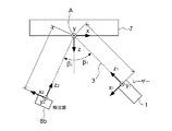
図1は、1つの実施形態に基づいて作成された、上述した式1を適用するための幾何学的配置を示す模式図である。ここでは、本発明の実施形態の一例を、図2に示す概略的な構成図を用いて説明する。
FIG. 1 is a schematic diagram showing a geometric arrangement for applying
この実施形態において、光源1は波長532nmのレーザーとして形成されている。レーザーによって発生された出発ビーム2は、ビームスプリッタによって、測定ビーム3と、第1の参照ビーム4aと、第2の参照ビーム4bと、第3の参照ビーム4cとに分割される。
In this embodiment, the
ビームスプリッタは、そのために、複数のビームスプリッタ5a、5bおよび5cを含んでいる。測定ビーム3は、第1のレンズユニット6aを経て、被測定物体7上の測定点Aにフォーカスされる。測定点Aにおける物体7の表面によって反射された測定ビームは、再び、第1のレンズユニット6aのビーム経路に入射し、光の重ね合わせ手段を経て第1の検出器8aにフォーカスされる。ここで第1の検出器8aは2個の光検出器8a’と8a’’とを含んでいる。光の重ね合わせ手段は、反射鏡Mと、偏光ビームスプリッタPBSとを含んでいる。検出器は、2個の光検出器8a’および8a’’上でビームを重ね合わせるため、さらに別のビームスプリッタ8a’’’を備えている。したがって、第1の光検出器の構造は、それ自体公知のいわゆる「平衡検波器」システムの構造と同じである。
For this purpose, the beam splitter includes a plurality of
ここでは、測定ビームと第1の参照ビームとのビーム経路の絞り孔A(測定点Aでもある)によって共焦点系が実現されている。
さらに、測定ビーム3のビーム経路には、測定ビームとすべての参照ビームとに関するヘテロダイン構造を形成すべく、ブラッグセルとして形成された周波数シフタ9が配置されている。別の形態として、周波数シフタ9は1つまたは2つの参照ビームのビーム経路に配置されてもよい。
Here, a confocal system is realized by an aperture A (also a measurement point A) in the beam path of the measurement beam and the first reference beam.
Further, a frequency shifter 9 formed as a Bragg cell is arranged in the beam path of the
第1の測定ビームはそれ自体公知の方法で、望遠鏡Tとλ/4波長板QWPとを経て、物体7上の測定点Aにフォーカスさせられ、同様に、再入射した、反射測定ビームはこれらの光学素子を経て第1の検出器8aにフォーカスされる。
The first measurement beam is known per se, is focused on the measurement point A on the
図2に示す装置構成では、さらに、第1の検出器8aと同様、2個の光検出器8b’と8b’’ならびに、平衡検波器システムに代わるビームスプリッタ8b’’’を有する第2の検出器8bを含んでいる。物体7上の測定点Aで散乱させられた測定光成分は第1の受信ビーム4b’として部分的に第2のレンズユニット6bによって収集され、第2の検出器8bにおいて、反射鏡M及びさらに別の望遠鏡Tとを経て入ってくる第2の参照ビーム4bと重ね合わされる。
In the apparatus configuration shown in FIG. 2, a second detector having two
同様に、物体7の点Aで異なる空間角で散乱させられた測定光成分を第2の受信ビーム4c’として収集し、反射鏡Mを経て、第3の検出器8cにフォーカスさせる第3のレンズユニット6cが設けられている。この経路では、第3の検出器8cは上記の第2の検出器8bと同様な構造であり、2個の光検出器8c’と8c’’ならびにビームスプリッタ8c’’’を有している。ここでも同様に、レンズユニット6cによって収集された測定ビームの散乱光成分は、光検出器8c’および8c’’の測定面にて、第3の参照ビーム4cと重ね合わされる。
Similarly, a measurement light component scattered at a different spatial angle at the point A of the
この装置は、測定ビーム3が測定点Aでの物体7の面法線に対してほぼ垂直をなして当たるように配置されるように形成されている。
This device is configured such that the
第1のレンズユニット6aによって発生させられた測定点は5μm以下の直径を有している。そのため、第1のレンズユニットは約0.2の開口数を有している。他方、第2と第3のレンズユニット6bおよび6cの開口数は約0.1である。
The measurement points generated by the
3個の検出器8a、8bおよび8cは、光検出器の測定信号の振幅復調および/または位相復調を実施すべく、それ自体公知の方法で形成された(図中不図示の)評価装置と接続されている。
The three
したがって、たとえば物体7の表面上の測定点Aの動きを三次元にて測定することができ、しかも、この測定は、従来の技術に関連して既述した外乱効果を生ずることなく、直径5μmの単一の測定点にて実施可能となる。
Thus, for example, the movement of the measurement point A on the surface of the
三次元振動情報を評価するため、好ましくは式1に準拠して、方向依存ドップラー効果が利用される。式1に由来する幾何学的パラメータの意味は、図1に示す概略的な図解から理解することができる。
In order to evaluate the three-dimensional vibration information, the direction dependent Doppler effect is preferably used in accordance with
レーザーとして形成された光源からの出発ビームは測定ビーム3と複数の参照ビームとに分割されるが、その際、光源は、測定ビーム3が物体7の面法線と角度β1をなして測定点Aに当たるように配置されている。この面法線は、さらに、xy面と、この面に対して垂直をなすz軸とを規定している。第2の検出器8bは、面法線に対して角度β2をなすように配置されている。
A starting beam from a light source formed as a laser is split into a
上述したように、図2は本発明による装置の1つの実施形態の概略的な構成を図示しており、その図では、わかり易くするために、すべてのビーム経路は二次元にて描画されている。 As mentioned above, FIG. 2 illustrates the schematic configuration of one embodiment of the apparatus according to the present invention, in which all beam paths are drawn in two dimensions for clarity. .
図3では、特に、測定点Aにおける物体、つまり被測定物体7の面法線によって定義されたx、yおよびz座標に関する三次元図解の形で、光源1と、第1の検出器8aと、第2の検出器8bと、第3の検出器8cとの実際の空間的配置が示されている。特に、40°以下であるのが好ましい角度φdetが示されている。
In FIG. 3, in particular, in the form of a three-dimensional illustration for the x, y and z coordinates defined by the surface normal of the object at the measurement point A, ie the object to be measured 7, the
図4には、本発明による装置の実施形態の2つの形態が図4の(a)と(b)にそれぞれ部分的に示されている。図4の(a)には、単に1個のレンズユニットによって測定ビーム3が被測定物体7上の測定点Aにフォーカスされると共に、それに対して斜めをなす空間角φdetにて第1の参照ビーム4aが1個の同一のレンズユニットによって、その他の光学素子を経て、第2の検出器にフォーカスされるように構成された実施形態例が表されている。
In FIG. 4, two forms of embodiments of the device according to the invention are partially shown in FIGS. 4 (a) and 4 (b), respectively. In FIG. 4A, the
他方、図4の(b)には、第1のレンズユニット6aによって測定ビーム3が物体7上の測定点Aにフォーカスさせられ、測定ビーム3の散乱光成分は第2のレンズユニット6bにより、その他の光学素子を経て、第2の検出器8bにフォーカスされるように構成された実施形態例が表されている。
On the other hand, in FIG. 4B, the
1 :光源
2 :出発ビーム
3 :測定ビーム
4a :第1の参照ビーム
4b :第2の参照ビーム
4b’:第1の受信ビーム
5a :ビームスプリッタ
7 :物体(被測定物体)
8a :第1の検出器
8b :第2の検出器
8c :第3の検出器
M :反射鏡(重ね合わせ手段)
PBS:偏光ビームスプリッタ(重ね合わせ手段)
1: Light source 2: Starting beam 3:
8a:
PBS: Polarizing beam splitter (superposition means)
Claims (15)
前記重ね合わせ手段と第1の検出器とは互いに連携するように形成されて、物体によって少なくとも部分的に反射された測定ビームと第1の参照ビームとが第1の検出器の少なくとも1つの検出面で重ね合わされ、
前記ビームスプリッタは、前記出発ビームを測定ビームと、第1の参照ビームと、少なくとも第2の参照ビームとに分割するように形成され、
前記重ね合わせ手段と互いに連係する少なくとも第2の検出器が備えられ、前記物体によって少なくとも部分的に散乱させられた第1の受信ビームとしての前記測定ビームと前記第2の参照ビームとが前記第2の検出器の少なくとも1つの検出面で重ね合わされることを特徴とする光干渉測定装置。 An apparatus for measuring optical interference of an object, comprising: a light source that generates a starting beam; a beam splitter that divides the starting beam into a measurement beam and a first reference beam; a light superimposing unit; and a first detector. And
The superimposing means and the first detector are formed so as to cooperate with each other, and the measurement beam and the first reference beam reflected at least partially by the object are detected by at least one of the first detectors. Superimposed on the surface,
The beam splitter is formed to split the starting beam into a measurement beam, a first reference beam, and at least a second reference beam;
At least a second detector associated with the superimposing means is provided, wherein the measurement beam as the first received beam and the second reference beam scattered at least partially by the object are the first detector beam. An optical interference measurement apparatus, wherein the optical interference measurement apparatus is superposed on at least one detection surface of two detectors.
少なくとも第3の検出器が備えられ、重ね合わせ手段と前記第3の検出器とは互いに連携するように形成され、物体によって少なくとも部分的に散乱させられた第2の受信ビームとしての測定ビームと第3の参照ビームとが前記第3の検出器の少なくとも1つの検出面で重ね合わされるように構成されているか、あるいは、
前記測定ビームと前記第2の参照ビームとによって定義される第1の面が前記測定ビームと前記第3の参照ビームとによって形成される第2の面と45°以上の挟角、好ましくは85°以上の挟角をなすように構成されていることを特徴とする請求項1から6のいずれか1項に記載の光干渉測定装置。 The beam splitter is configured to split a starting beam into at least a third reference beam in addition to the measurement beam, the first reference beam, and the second reference beam;
A measuring beam as a second received beam, provided with at least a third detector, wherein the superimposing means and the third detector are formed to cooperate with each other and are at least partially scattered by the object; A third reference beam is configured to overlap at least one detection surface of the third detector, or
The first surface defined by the measurement beam and the second reference beam is at an included angle of 45 ° or more, preferably 85, with the second surface formed by the measurement beam and the third reference beam. The optical interference measuring apparatus according to any one of claims 1 to 6, wherein the optical interference measuring apparatus is configured to form an included angle of not less than °.
前記出発ビームをビームスプリッタによって測定ビームと第1の参照ビームとに分割するBステップと、
前記第1の参照ビームと、物体によって少なくとも部分的に反射された前記測定ビームとを第1の検出器の少なくとも1つの検出面で重ね合わせるCステップと、
を含む物体の光干渉測定方法であって、
前記Bステップにおいて、前記出発ビームはさらに少なくとも第2の参照ビームに分割され、前記第2の参照ビームは、前記物体によって少なくとも部分的に散乱させられた前記測定ビームと、第2の検出器の少なくとも1つの検出面で重ね合わされることを特徴とする光干渉測定方法。 A step of generating a starting beam by a light source;
B step of splitting the starting beam into a measurement beam and a first reference beam by a beam splitter;
Superimposing said first reference beam and said measurement beam at least partially reflected by an object on at least one detection surface of a first detector;
A method for measuring optical interference of an object including:
In step B, the starting beam is further split into at least a second reference beam, the second reference beam being at least partially scattered by the object, and a second detector An optical interference measurement method, wherein the optical interference measurement method is superposed on at least one detection surface.
Applications Claiming Priority (2)
| Application Number | Priority Date | Filing Date | Title |
|---|---|---|---|
| DE102011085599A DE102011085599B3 (en) | 2011-11-02 | 2011-11-02 | Apparatus and method for interferometric measurement of an object |
| DE102011085599.8 | 2011-11-02 |
Related Child Applications (1)
| Application Number | Title | Priority Date | Filing Date |
|---|---|---|---|
| JP2018090906A Division JP6631978B2 (en) | 2011-11-02 | 2018-05-09 | Optical interference measuring apparatus and optical interference measuring method for object |
Publications (1)
| Publication Number | Publication Date |
|---|---|
| JP2013096997A true JP2013096997A (en) | 2013-05-20 |
Family
ID=47137545
Family Applications (2)
| Application Number | Title | Priority Date | Filing Date |
|---|---|---|---|
| JP2012242650A Pending JP2013096997A (en) | 2011-11-02 | 2012-11-02 | Optical interference measuring instrument and optical interference measuring method for object |
| JP2018090906A Active JP6631978B2 (en) | 2011-11-02 | 2018-05-09 | Optical interference measuring apparatus and optical interference measuring method for object |
Family Applications After (1)
| Application Number | Title | Priority Date | Filing Date |
|---|---|---|---|
| JP2018090906A Active JP6631978B2 (en) | 2011-11-02 | 2018-05-09 | Optical interference measuring apparatus and optical interference measuring method for object |
Country Status (6)
| Country | Link |
|---|---|
| US (1) | US10018460B2 (en) |
| EP (1) | EP2589924B1 (en) |
| JP (2) | JP2013096997A (en) |
| CN (1) | CN103090786B (en) |
| DE (1) | DE102011085599B3 (en) |
| SG (1) | SG189672A1 (en) |
Families Citing this family (6)
| Publication number | Priority date | Publication date | Assignee | Title |
|---|---|---|---|---|
| US9829373B1 (en) * | 2014-09-19 | 2017-11-28 | The United States Of America As Represented By The Secretary Of The Army | Apparatus and method for improving detection precision in laser vibrometric studies |
| DE102015003019A1 (en) | 2015-03-06 | 2016-09-08 | Fraunhofer-Gesellschaft zur Förderung der angewandten Forschung e.V. | Method and device for the optical detection of movement in a biological sample with spatial extent |
| DE102018111921B4 (en) * | 2018-05-17 | 2023-11-23 | Technische Universität Clausthal | Contactless optical strain gauge sensor |
| CN108548489A (en) * | 2018-05-24 | 2018-09-18 | 郑州辰维科技股份有限公司 | A method of precision measure being carried out to solid surface antenna using optical markers |
| CN108548506A (en) * | 2018-05-24 | 2018-09-18 | 郑州辰维科技股份有限公司 | A method of the measurement of planeness being carried out to high precision plane using optical markers |
| CN111307268B (en) * | 2020-03-11 | 2021-01-01 | 北京理工大学 | Laser confocal/differential confocal vibration parameter measuring method |
Citations (8)
| Publication number | Priority date | Publication date | Assignee | Title |
|---|---|---|---|---|
| JPH01145504A (en) * | 1987-12-01 | 1989-06-07 | Canon Inc | Optically measuring apparatus |
| JPH07297248A (en) * | 1994-04-20 | 1995-11-10 | Hitachi Ltd | Crystal defect measuring device and method of manufacturing semiconductor device |
| JPH10227617A (en) * | 1997-02-12 | 1998-08-25 | Nikon Corp | Mocroline width measuring method and apparatus |
| US5883714A (en) * | 1996-10-07 | 1999-03-16 | Phase Metrics | Method and apparatus for detecting defects on a disk using interferometric analysis on reflected light |
| JP2001066247A (en) * | 1999-08-26 | 2001-03-16 | Japan Science & Technology Corp | Photometric apparatus |
| DE102007010389A1 (en) * | 2007-03-03 | 2008-09-04 | Polytec Gmbh | Device for optical measurement of objects, has signal evaluation unit, and interferometer with light source and detectors, where light source is formed so that it generates light with coherence length smaller than one centimeter |
| WO2009079031A1 (en) * | 2007-12-18 | 2009-06-25 | Quality Vision International | Partial coherence interferometer with measurement ambiguity resolution |
| JP2009250983A (en) * | 2008-04-02 | 2009-10-29 | Polytec Gmbh | Vibration meter and object optically measuring method |
Family Cites Families (23)
| Publication number | Priority date | Publication date | Assignee | Title |
|---|---|---|---|---|
| GB1472894A (en) * | 1974-03-15 | 1977-05-11 | Nat Res Dev | Interferometric methods and apparatus for measuring distance to a surface |
| US5087121A (en) | 1987-12-01 | 1992-02-11 | Canon Kabushiki Kaisha | Depth/height measuring device |
| JPH01282488A (en) * | 1988-05-10 | 1989-11-14 | Asahi Glass Co Ltd | Optical fiber sensor |
| CA2007190C (en) * | 1990-01-04 | 1998-11-24 | National Research Council Of Canada | Laser optical ultrasound detection |
| US5229832A (en) * | 1991-07-08 | 1993-07-20 | Industrial Quality, Inc. | Optical ultrasonic material characterization apparatus and method |
| FR2750215B1 (en) * | 1996-06-25 | 1998-09-11 | Sextant Avionique | OPTICAL VELOCIMETRIC PROBE |
| US6137585A (en) * | 1998-05-15 | 2000-10-24 | Laser Diagnostic Technologies, Inc. | Method and apparatus for recording three-dimensional distribution of light backscattering potential in transparent and semi-transparent structures |
| US6320665B1 (en) * | 1998-12-29 | 2001-11-20 | Bryan Kok Ann Ngoi | Acousto optic scanning laser vibrometer for determining the dynamic properties of an object |
| JP2001208974A (en) * | 2000-01-24 | 2001-08-03 | Nikon Corp | Confocal type microscope and collective illumination type microscope |
| US6744520B2 (en) * | 2002-03-04 | 2004-06-01 | Industrial Technology Research Institute | Method for measuring two-dimensional displacement using conjugate optics |
| KR101223195B1 (en) * | 2002-09-09 | 2013-01-21 | 지고 코포레이션 | Interferometry method and apparatus for ellipsometry, relectometry, and scatterometry measurements, including characterization of thin film structure |
| US6972846B2 (en) * | 2003-03-31 | 2005-12-06 | Metrolaser, Inc. | Multi-beam heterodyne laser doppler vibrometer |
| US7289224B2 (en) * | 2003-09-15 | 2007-10-30 | Zygo Corporation | Low coherence grazing incidence interferometry for profiling and tilt sensing |
| JP4093971B2 (en) * | 2004-02-12 | 2008-06-04 | シャープ株式会社 | Optical movement information detection apparatus, movement information detection system, electronic apparatus and encoder |
| JP4409331B2 (en) * | 2004-03-30 | 2010-02-03 | 株式会社トプコン | Optical image measuring device |
| CA2564945A1 (en) * | 2004-05-05 | 2005-11-17 | Presstek, Inc. | Graphic-arts laser imaging with reduced-length laser cavities and improved performance |
| US7405814B2 (en) * | 2006-12-19 | 2008-07-29 | The Boeing Company | Frequency multiplexed, multiple channel heterodyne interferometer |
| JP4264667B2 (en) * | 2007-02-16 | 2009-05-20 | ソニー株式会社 | Vibration detector |
| DE102007010387B4 (en) * | 2007-03-03 | 2013-02-21 | Polytec Gmbh | Interferometer for optical measurement of an object |
| CN100491901C (en) * | 2007-08-08 | 2009-05-27 | 北京交通大学 | Synthetic wave interference nano surface tri-dimensional on-line measuring system and method |
| CN100567884C (en) * | 2008-05-06 | 2009-12-09 | 哈尔滨工业大学 | Second confocal measuring method and device based on movable phase interfere |
| WO2010057169A2 (en) * | 2008-11-17 | 2010-05-20 | Faro Technologies, Inc. | Device and method for measuring six degrees of freedom |
| DE102012211549B3 (en) * | 2012-07-03 | 2013-07-04 | Polytec Gmbh | Apparatus and method for interferometric measurement of an object |
-
2011
- 2011-11-02 DE DE102011085599A patent/DE102011085599B3/en not_active Expired - Fee Related
-
2012
- 2012-10-15 EP EP12188513.1A patent/EP2589924B1/en active Active
- 2012-10-30 SG SG2012080263A patent/SG189672A1/en unknown
- 2012-11-02 US US13/667,309 patent/US10018460B2/en active Active
- 2012-11-02 JP JP2012242650A patent/JP2013096997A/en active Pending
- 2012-11-02 CN CN201210434215.5A patent/CN103090786B/en active Active
-
2018
- 2018-05-09 JP JP2018090906A patent/JP6631978B2/en active Active
Patent Citations (10)
| Publication number | Priority date | Publication date | Assignee | Title |
|---|---|---|---|---|
| JPH01145504A (en) * | 1987-12-01 | 1989-06-07 | Canon Inc | Optically measuring apparatus |
| JPH07297248A (en) * | 1994-04-20 | 1995-11-10 | Hitachi Ltd | Crystal defect measuring device and method of manufacturing semiconductor device |
| US5883714A (en) * | 1996-10-07 | 1999-03-16 | Phase Metrics | Method and apparatus for detecting defects on a disk using interferometric analysis on reflected light |
| JPH10227617A (en) * | 1997-02-12 | 1998-08-25 | Nikon Corp | Mocroline width measuring method and apparatus |
| JP2001066247A (en) * | 1999-08-26 | 2001-03-16 | Japan Science & Technology Corp | Photometric apparatus |
| DE102007010389A1 (en) * | 2007-03-03 | 2008-09-04 | Polytec Gmbh | Device for optical measurement of objects, has signal evaluation unit, and interferometer with light source and detectors, where light source is formed so that it generates light with coherence length smaller than one centimeter |
| JP2008216251A (en) * | 2007-03-03 | 2008-09-18 | Polytec Gmbh | Optical measurement apparatus |
| WO2009079031A1 (en) * | 2007-12-18 | 2009-06-25 | Quality Vision International | Partial coherence interferometer with measurement ambiguity resolution |
| JP2010510529A (en) * | 2007-12-18 | 2010-04-02 | クオリティー ヴィジョン インターナショナル インコーポレイテッド | Partial coherence interferometer eliminating measurement ambiguity |
| JP2009250983A (en) * | 2008-04-02 | 2009-10-29 | Polytec Gmbh | Vibration meter and object optically measuring method |
Also Published As
| Publication number | Publication date |
|---|---|
| DE102011085599B3 (en) | 2012-12-13 |
| CN103090786B (en) | 2017-07-18 |
| JP6631978B2 (en) | 2020-01-15 |
| CN103090786A (en) | 2013-05-08 |
| JP2018119991A (en) | 2018-08-02 |
| EP2589924A1 (en) | 2013-05-08 |
| US20130107276A1 (en) | 2013-05-02 |
| SG189672A1 (en) | 2013-05-31 |
| US10018460B2 (en) | 2018-07-10 |
| EP2589924B1 (en) | 2016-04-20 |
Similar Documents
| Publication | Publication Date | Title |
|---|---|---|
| JP6631978B2 (en) | Optical interference measuring apparatus and optical interference measuring method for object | |
| JP4505807B2 (en) | Multiplexed spectral interferometric optical coherence tomography | |
| US10429171B2 (en) | Laser multibeam differential interferometric sensor and methods for vibration imaging | |
| EP2163906B1 (en) | Method of detecting a movement of a measuring probe and measuring instrument | |
| US20060039007A1 (en) | Vibration-insensitive interferometer | |
| JP2007024827A (en) | Phase shift interferometer | |
| JPWO2020017017A1 (en) | Optical measuring device and sample observation method | |
| JP2013152191A (en) | Multi-wavelength interferometer | |
| JP4852651B2 (en) | Multiplexed spectral interferometric optical coherence tomography | |
| JP2006250849A (en) | Optical image measuring method using light coherence tomography apparatus and optical image measuring device | |
| CN104823029A (en) | Method of vibration measurement and interferometer | |
| JP3843399B2 (en) | Method and apparatus for determining a three-dimensional structure in the submicrometer range | |
| JP2013257302A (en) | Heterodyne interference device | |
| US20110299090A1 (en) | Real-time interferometer | |
| JP5149923B2 (en) | Multiplexed spectral interferometric optical coherence tomography | |
| JP2002148025A (en) | Three-dimensional shape measuring apparatus | |
| JP2007292650A (en) | Optical interferometer | |
| JP2001264036A (en) | Measuring apparatus and measuring method for surface shape | |
| JP4536873B2 (en) | Three-dimensional shape measuring method and apparatus | |
| JP2020153992A (en) | Shape measurement device by white interferometer | |
| JP3410800B2 (en) | Vibration resistant interferometer | |
| SU1578462A1 (en) | Method of measuring angular rotations of object | |
| JP3466713B2 (en) | Measuring device | |
| JPH0545140A (en) | Method and device for measuring radius of curvature | |
| JPS6334402B2 (en) |
Legal Events
| Date | Code | Title | Description |
|---|---|---|---|
| A621 | Written request for application examination |
Free format text: JAPANESE INTERMEDIATE CODE: A621 Effective date: 20150825 |
|
| A977 | Report on retrieval |
Free format text: JAPANESE INTERMEDIATE CODE: A971007 Effective date: 20160726 |
|
| A131 | Notification of reasons for refusal |
Free format text: JAPANESE INTERMEDIATE CODE: A131 Effective date: 20160802 |
|
| A601 | Written request for extension of time |
Free format text: JAPANESE INTERMEDIATE CODE: A601 Effective date: 20161101 |
|
| A601 | Written request for extension of time |
Free format text: JAPANESE INTERMEDIATE CODE: A601 Effective date: 20161228 |
|
| A521 | Request for written amendment filed |
Free format text: JAPANESE INTERMEDIATE CODE: A523 Effective date: 20170202 |
|
| A131 | Notification of reasons for refusal |
Free format text: JAPANESE INTERMEDIATE CODE: A131 Effective date: 20170711 |
|
| A601 | Written request for extension of time |
Free format text: JAPANESE INTERMEDIATE CODE: A601 Effective date: 20171011 |
|
| A02 | Decision of refusal |
Free format text: JAPANESE INTERMEDIATE CODE: A02 Effective date: 20180109 |