JP2012520179A - Roller with drive shaft and roller ring and method for assembling such a roller - Google Patents
Roller with drive shaft and roller ring and method for assembling such a roller Download PDFInfo
- Publication number
- JP2012520179A JP2012520179A JP2011553982A JP2011553982A JP2012520179A JP 2012520179 A JP2012520179 A JP 2012520179A JP 2011553982 A JP2011553982 A JP 2011553982A JP 2011553982 A JP2011553982 A JP 2011553982A JP 2012520179 A JP2012520179 A JP 2012520179A
- Authority
- JP
- Japan
- Prior art keywords
- roller
- ring
- drive shaft
- hand
- diameter
- Prior art date
- Legal status (The legal status is an assumption and is not a legal conclusion. Google has not performed a legal analysis and makes no representation as to the accuracy of the status listed.)
- Pending
Links
Images


Classifications
-
- B—PERFORMING OPERATIONS; TRANSPORTING
- B21—MECHANICAL METAL-WORKING WITHOUT ESSENTIALLY REMOVING MATERIAL; PUNCHING METAL
- B21B—ROLLING OF METAL
- B21B27/00—Rolls, roll alloys or roll fabrication; Lubricating, cooling or heating rolls while in use
- B21B27/02—Shape or construction of rolls
- B21B27/03—Sleeved rolls
- B21B27/035—Rolls for bars, rods, rounds, tubes, wire or the like
-
- B—PERFORMING OPERATIONS; TRANSPORTING
- B21—MECHANICAL METAL-WORKING WITHOUT ESSENTIALLY REMOVING MATERIAL; PUNCHING METAL
- B21B—ROLLING OF METAL
- B21B27/00—Rolls, roll alloys or roll fabrication; Lubricating, cooling or heating rolls while in use
- B21B27/02—Shape or construction of rolls
- B21B27/03—Sleeved rolls
-
- B—PERFORMING OPERATIONS; TRANSPORTING
- B23—MACHINE TOOLS; METAL-WORKING NOT OTHERWISE PROVIDED FOR
- B23P—METAL-WORKING NOT OTHERWISE PROVIDED FOR; COMBINED OPERATIONS; UNIVERSAL MACHINE TOOLS
- B23P11/00—Connecting or disconnecting metal parts or objects by metal-working techniques not otherwise provided for
- B23P11/02—Connecting or disconnecting metal parts or objects by metal-working techniques not otherwise provided for by first expanding and then shrinking or vice versa, e.g. by using pressure fluids; by making force fits
- B23P11/025—Connecting or disconnecting metal parts or objects by metal-working techniques not otherwise provided for by first expanding and then shrinking or vice versa, e.g. by using pressure fluids; by making force fits by using heat or cold
-
- F—MECHANICAL ENGINEERING; LIGHTING; HEATING; WEAPONS; BLASTING
- F16—ENGINEERING ELEMENTS AND UNITS; GENERAL MEASURES FOR PRODUCING AND MAINTAINING EFFECTIVE FUNCTIONING OF MACHINES OR INSTALLATIONS; THERMAL INSULATION IN GENERAL
- F16C—SHAFTS; FLEXIBLE SHAFTS; ELEMENTS OR CRANKSHAFT MECHANISMS; ROTARY BODIES OTHER THAN GEARING ELEMENTS; BEARINGS
- F16C13/00—Rolls, drums, discs, or the like; Bearings or mountings therefor
-
- Y—GENERAL TAGGING OF NEW TECHNOLOGICAL DEVELOPMENTS; GENERAL TAGGING OF CROSS-SECTIONAL TECHNOLOGIES SPANNING OVER SEVERAL SECTIONS OF THE IPC; TECHNICAL SUBJECTS COVERED BY FORMER USPC CROSS-REFERENCE ART COLLECTIONS [XRACs] AND DIGESTS
- Y10—TECHNICAL SUBJECTS COVERED BY FORMER USPC
- Y10T—TECHNICAL SUBJECTS COVERED BY FORMER US CLASSIFICATION
- Y10T29/00—Metal working
- Y10T29/49—Method of mechanical manufacture
- Y10T29/49544—Roller making
- Y10T29/49547—Assembling preformed components
- Y10T29/49549—Work contacting surface element assembled to core
- Y10T29/49552—Work contacting surface element assembled to core with prestressing of component by heat differential, e.g., shrink, fit
Abstract
一方では一定の外径と一定の長さとを有する円筒形の外表面(6)を有する駆動シャフト(1)と、他方ではより短いローラリング(2)とを具備するタイプのローラであって、ローラリングが、硬い材料から作成される外部リング(4)と、外部リングと同軸であると共により延性のある材料から作成される内部リング(3)とを含み、内部リングが、一定の内径を有する円筒形の内面を含み、かつ一方では冶金的なやり方で外部リングに永続的に結合され、他方では、駆動シャフトから外部リングにトルクを伝達するために、駆動シャフトと回転方向に固く接続されるローラに関する。本発明によれば、駆動シャフトとローラリングとの間における、回転方向に固い結合作用は、締りばめ接合のみからなり、この締りばめ接合は、駆動シャフトの外表面と内部リングの内面との間で行われ、駆動シャフトの外径の少なくとも0.01%の締めしろを有する。 A roller of the type comprising a drive shaft (1) having a cylindrical outer surface (6) having a constant outer diameter and a constant length on the one hand and a shorter roller ring (2) on the other hand, The roller ring includes an outer ring (4) made from a hard material and an inner ring (3) made from a more ductile material that is coaxial with the outer ring, the inner ring having a constant inner diameter. With a cylindrical inner surface and, on the one hand, permanently connected to the outer ring in a metallurgical manner, and on the other hand, firmly connected to the drive shaft in the rotational direction for transmitting torque from the drive shaft to the outer ring. Related to the roller. According to the present invention, the hard coupling action in the rotational direction between the drive shaft and the roller ring consists only of an interference fit joint, and this interference fit joint is performed between the outer surface of the drive shaft and the inner surface of the inner ring. With a margin of at least 0.01% of the outer diameter of the drive shaft.
Description
第一の態様では、本発明は、一方では一定の外径と一定の長さとを有する円筒形の外表面を有する駆動シャフトと、他方ではローラリングとを具備するタイプのローラであって、ローラリングは、硬い材料から作成される外部リングと、外部リングと同軸であると共により延性のある材料から作成される内部リングとを含み、内部リングは、一定の内径を有する円筒形の内面を含み、かつ一方では冶金的なやり方で外部リングに永続的に結合され、他方では、駆動シャフトから外部リングに駆動トルクを伝達するために、駆動シャフトと回転方向に固く接続される、ローラに関する。 In a first aspect, the present invention is a roller of the type comprising a drive shaft having a cylindrical outer surface having a constant outer diameter and a length on the one hand, and a roller ring on the other hand. The ring includes an outer ring made from a hard material and an inner ring that is coaxial with the outer ring and made from a more ductile material, the inner ring including a cylindrical inner surface having a constant inner diameter. And, on the one hand, permanently connected to the outer ring in a metallurgical manner, and on the other hand to a roller which is firmly connected in the rotational direction with the drive shaft in order to transmit drive torque from the drive shaft to the outer ring.
さらなる態様では、本発明はこのようなローラを組立てる方法にも関する。 In a further aspect, the invention also relates to a method for assembling such a roller.
上記記載において概ね言及されたタイプのローラは、当業者にコンビローラ(combi rollers)と称され、実際には、ワイヤ、バー、チューブなどの金属の細長い製造物の熱間圧延又は冷間圧延に使用される。このために、ローラリングには、所望の配列の製造物を形成する1又は複数の円周溝が形成される。ローラリングは、細長片などの平坦な物体を圧延する場合には、全体的に平滑であってもよい。一部のローラでは、ローラリングは、例えばノジュラ鉄(nodular iron)である鉄を原材料とした鋳造合金から作成される内部リングと1又は複数の外部リングとから製造されるタイプのいわゆる複合ローラリングからなる。外部リングは、内部リングに埋め込まれ、超硬合金などの耐磨耗性でありかつ耐熱性である硬い材料から形成されている。外部リングは、冶金的なやり方で内部リングに永続的に結合され、さらに厳密には、鋳造の際に合金に外部リングを埋め込むことによって、永続的に結合される。 Rollers of the type generally referred to in the above description are referred to by those skilled in the art as combi rollers, and are actually used for hot or cold rolling of elongated metal products such as wires, bars and tubes. used. For this purpose, the roller ring is formed with one or more circumferential grooves that form the desired array of products. The roller ring may be entirely smooth when rolling a flat object such as an elongated piece. In some rollers, the roller ring is a so-called composite roller ring of the type manufactured from an inner ring made of a cast alloy made from iron, eg, nodular iron, and one or more outer rings. Consists of. The outer ring is embedded in the inner ring and is formed of a hard material that is wear resistant and heat resistant, such as a cemented carbide. The outer ring is permanently bonded to the inner ring in a metallurgical manner, and more precisely, by permanently embedding the outer ring in the alloy during casting.
このような類のローラにおいて、超硬合金から作成されるローラリングを使用することには長年の開発の歴史がある。この長年の歴史は、超硬合金リングを駆動シャフトと単なる機械的なやり方(楔、突起(lugs)、バー又は他の駆動体)で直接に接続しようとしていた簡易なローラ構成から、個々の超硬合金リングが通常はより延性のある材料から作成される内部リングを用いて冶金的に結合され、次いで超硬合金リングに起こる邪魔な応力現象なしに、内部リングを駆動シャフトに取り付けることができる、今日の構成まで至るものである。近年では、開発は、2つの主な問題点に、すなわち、第一にローラリングの材料の選択、ひいては特に内部リングの適切な材料の選択と、第二にローラリングを駆動シャフトに対して回転するように確実に固定させるという問題とに注目されている。内部リングの材料に関する他のもの(特許文献1参照)の間における材料の開発により、分散した球状黒鉛を含むマグネシウム含有の(magnesious)ノジュラ鉄を使用する結果となった。マグネシウムノジュラ鉄を、熱処理によって、例えばベイナイトに変換することによって適切な量の残留オーステナイトを除くことができる。第2の問題を解決するための試験により、すなわち大きなトルクを駆動シャフトからローラリングに、これらが互いに対して摺動することなしに伝達することができるようにする試験により、多数の解決策の提案がもたらされ、これらの解決策は、特許文献に十分に記されている(上述の特許文献1に加えて、さらに特許文献2〜5も参照すること。)。しかしながら、これまでに知られている解決策に共通していることは、駆動シャフトからローラリングへのトルクが未だに、何らかの形で駆動シャフトとローラリングの内部リングとの間で作用する機械的なロック手段を介してもたらされていることである。ロック手段の1つのカテゴリは雄及び雌の要素からなり、雄及び雌の要素は、互いに係合し、内部リングの内面と駆動シャフトの外表面との間の接触面に、又はローラリングと互いに押圧される駆動シャフトの外側で協働する複数のリングとの端面に配置される(両方の場合において、特許文献1参照)。別のカテゴリのロック手段は協働する表面同士の間の摩擦接合に依存する。さらに、この場合では、この接合作用は、内部リングの内面と駆動シャフトの外表面との間の接触面に、又はローラリングと協働する、リングのリング形状をした端面に位置してもよい。このような摩擦接合を実現するために、楔、ロックナット、液圧装置等を使用することができる。
In this type of roller, the use of roller rings made from cemented carbide has a long history of development. This long history has led to the individual superstructures from the simple roller configuration that was trying to connect the cemented carbide ring directly to the drive shaft in a mere mechanical manner (wedges, lugs, bars or other drive). The hard alloy ring can be metallurgically bonded using an inner ring, usually made from a more ductile material, and then the inner ring can be attached to the drive shaft without the disturbing stress phenomenon that occurs with cemented carbide rings , To today's composition. In recent years, development has addressed two main problems: firstly the choice of material for the roller ring, and in particular the choice of the appropriate material for the inner ring, and secondly the rotation of the roller ring relative to the drive shaft. Attention has been paid to the problem of securely fixing. The development of the material among others related to the material of the inner ring (see US Pat. No. 6,057,097) has resulted in the use of magnesium nodular iron with dispersed spheroidal graphite. A suitable amount of retained austenite can be removed by converting the magnesium nodular iron into a bainite by heat treatment, for example. Tests to solve the second problem, i.e. tests that allow a large torque to be transmitted from the drive shaft to the roller ring without sliding against each other, Proposals have been made and these solutions are well documented in the patent literature (see also patent documents 2-5 in addition to the above-mentioned patent document 1). However, what is common to the solutions known so far is that the torque from the drive shaft to the roller ring still acts in some way between the drive shaft and the inner ring of the roller ring. It comes from the locking means. One category of locking means consists of male and female elements, the male and female elements engaging each other and at the contact surface between the inner surface of the inner ring and the outer surface of the drive shaft or with the roller ring. It arrange | positions at the end surface with the some ring which cooperates on the outer side of the drive shaft pressed (refer
しかしながら、最も簡易な機械的なロック手段の欠点は、このロック手段が何らかの形で必須の旋削、すなわちフライス削り、穿孔加工、ネジ山形成加工等に加えて切削加工又はチップ除去加工(chip removing machining)を必要とすることにある。このような追加的な加工作用の各々は、個々の作業に時間がかかるという事実の結果としてだけではなく、場合によってはとりわけ、準備時間を含めた、様々な加工部署同士の間で部品を移動しなければならないという事実の結果として、製造をより高価なものにする。機械的なロック手段の別の欠点は、所与のローラ幅の範囲内にローラリング(ローラリングの溝)をいくつ取り付けることができるかによって決定されるローラの収容能力を、機械的なロック手段が減少させることにある。ローラの収容能力は駆動シャフトの事実上の長さによって決められる。ロック手段がローラの幅に割り込むならば、当然に事実上のローラの溝の数が減少する。このときに、ロック手段はさらに、ローラリングに有害な応力現象を引き起こすおそれがある。加えて、具体的には、それぞれの構成要素の雌型の凹部は、ローラ構成の全体を脆弱にするおそれがある。 However, the disadvantage of the simplest mechanical locking means is that the locking means is in some form essential turning, ie milling, drilling, thread forming, etc., in addition to cutting or chip removing machining. ). Each of these additional machining operations not only as a result of the fact that individual operations take time, but in some cases, among other things, moving parts between various machining departments, including preparation time As a result of the fact that it has to be made, manufacturing is more expensive. Another disadvantage of the mechanical locking means is that the capacity of the roller, determined by how many roller rings (roller groove) can be mounted within a given roller width, Is to reduce. The capacity of the roller is determined by the actual length of the drive shaft. If the locking means cuts into the width of the roller, then of course the actual number of roller grooves is reduced. At this time, the locking means may further cause a stress phenomenon harmful to the roller ring. In addition, specifically, the female recesses of each component may make the entire roller configuration fragile.
本発明の目的は、上述の既知のローラの欠点を防ぎ、改善したローラを提供することにある。したがって、本発明の第一の目的はローラであって、従来の機械的なロック手段なしに、このローラのローラリングを駆動シャフトに対して信頼性のあるやり方で回転方向に固定することができる、ローラを提供することにある。さらなる目的は、駆動シャフトの長さ延長部に沿ってローラリング及びローラの溝の両方又は一方について最適な収容能力を有するローラを提供することにある。本発明のさらなる目的は、ローラであって、このローラの2つの主構成要素、すなわち駆動シャフトと1又は複数のローラリングとを、加工作用を絶対的に最小にすることによって製造することができる、ローラを提供することにある。 It is an object of the present invention to provide an improved roller that avoids the disadvantages of the known rollers described above. Accordingly, the primary object of the present invention is a roller, which can be secured in the direction of rotation in a reliable manner with respect to the drive shaft without conventional mechanical locking means. To provide a roller. It is a further object to provide a roller having optimal accommodation capacity for the roller ring and / or groove of the roller along the length extension of the drive shaft. A further object of the invention is a roller, the two main components of which can be manufactured by absolutely minimizing the machining action, namely the drive shaft and one or more roller rings. To provide a roller.
本発明によれば、少なくとも第一の目的は、請求項1の特徴的な条項に定義されている特徴によって達成される。さらに、本発明に係るローラの好ましい実施形態が従属請求項2〜4で定義されている。
According to the invention, at least the first object is achieved by the features defined in the characterizing clause of
さらなる態様において、本発明はさらに、本発明に係るローラを組立てる方法に関する。この方法の特徴は独立請求項5に記載されている。
In a further aspect, the invention further relates to a method for assembling a roller according to the invention. The features of this method are set forth in the
本発明は、正確な応力計算と駆動シャフトに対するローラリングの非常にバランスが取られた寸法設定とにより実現することのできる十分に強固な締まりばめ接合が、ローラリングを駆動シャフトに対して回転方向に固定するのに十分であるという、驚くべき理解に基づくものである。したがって、当該駆動シャフトの直径の少なくとも0.01%の締めしろ又は締まりばめ作用を用いた締まりばめ接合を施すことによって、2つの構成要素同士の間で全てのタイプの機械的なロック手段を排除したという事実にもかかわらず、駆動シャフトにおいて摺動することなくローラリングが十分なトルクを受けることができるということになる。したがって、直接的に、従来の設計理念に反して、必須な2つの主構成要素、すなわち駆動シャフト及び1つの(又は複数の)ローラリング以外に何も追加的な細部なしに、本発明に係るローラを製造することができる。 The present invention provides a sufficiently strong interference fit that can be achieved with accurate stress calculations and a very balanced sizing of the roller ring relative to the drive shaft, which rotates the roller ring relative to the drive shaft. It is based on a surprising understanding that it is sufficient to fix in a direction. Therefore, all types of mechanical locking means between the two components by applying an interference fit joint with an interference or interference fit action of at least 0.01% of the diameter of the drive shaft. Despite the fact that the roller ring is eliminated, the roller ring can receive sufficient torque without sliding on the drive shaft. Thus, directly and contrary to the conventional design philosophy, the present invention does not require any additional details other than the two essential components, namely the drive shaft and one (or more) roller ring. Rollers can be manufactured.
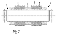
図面では、参照番号1は、ローラ又は駆動シャフトを全体的に示し、参照番号2は、ローラ又は駆動シャフトの外側に取り付けられたローラリングを示す。前記ローラリング2は、その外表面に内部リング3と2つの外部リング4とを備える。細長い製造物を回転させるための、外部リング4の周ローラ溝5が形成される。
In the drawings,
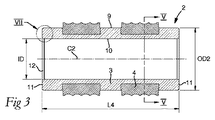
駆動シャフト1は、円筒形外表面6(図4参照)の形状のロールバレルを含む。このロールバレルは、駆動シャフトの中心軸線C1と同軸であり、互いに対向する端部では、減少した直径を有するシャフトジャーナル又はシャフト軸頚7を形成する外表面に変形している。この場合では、シャフトの2つの端部は、2つのシャフト軸頸7の平端面8からなる。シャフトの全長L1は、2つの端面8同士の間の距離によって決定される。各シャフト軸頸7が一定の長さL2を有するので、外表面6の軸線方向延長部又は軸線方向長さL3は、シャフトの全長L1よりも短い。外表面6にそったシャフトの外径はOD1となる(図6参照)。
The
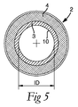
ローラリング2の内部リング3は外表面9と内表面又は内面10とを含み、これらの両方は、基本的には円筒形状を有し、ローラリングの中心軸線C2と同軸である。内部リングの2つの対向する端部はリング形状をした平面11からなり、これら端部の互いからの距離は、内部リングの軸線方向長さL4を決定する。図3及び図5では、内部リング3の内径がIDとなる一方で、内部リング3の外径がOD2となる。2つの外部リング4のそれぞれは、冶金的なやり方で内部リングに永続的に結合するように、内部リング3の外表面で鋳造される(cast−in)。この場合では、個々の外部リング4の外径(参照表示せず)は内部リングの外径OD2よりも大きい(これらは同じ大きさでもよい。)一方で、外部リングの内面は、一方では内部リングの外径よりも小さいが、しかし他方では内径IDよりも大きな直径を有する。ローラが組立てられると、ローラリング2の中心軸線C2が駆動シャフト1の中心軸線C1と一致することにも言及されるべきである。
The
実際には、スチール以外の材料も、特に(炭素の含有量の高い)比較的高い硬度を有する鋳鉄も使用可能であるものの、駆動シャフト1をスチールから製造することが好ましい。ローラリング2の外部リング4の材料として、有利には、従来の超硬合金、すなわちWC及び結合相(binder phase)、例えばCo又はCo+Ni+Crを含む超硬合金粉を圧縮し焼結することによって得られる粉末冶金材料が使用される。従来の超硬合金以外にも他の硬い材料を、例えば高速度鋼を使用することができることも指摘されるべきである。最後に、内部リング3の材料は、一般的に、金属又は金属合金などの、外部リングの硬い材料よりも延性のある材料からなる。ほとんどの場合では、ノジュラ鉄が好ましく、特許文献6に開示されているタイプのものが好ましい。
In practice, it is preferable to produce the
ローラの2つの主構成要素の製造は別々の作用によってもたらされる。駆動シャフト1は、円筒形ブランク(blank)から、外表面6及び軸頸7の外側を外部縦方向旋削することと端面8を表面旋削することとによって製造される。ローラリング2はブランクを鋳造することによって製造され、このブランクでは、あらかじめ形成されている超硬合金リングが、内部リングを形成すべきである液体のノジュラ鉄に埋め込まれる。このブランクは、旋削によって、すなわち外表面9の外部縦方向旋削と内面10の内部縦方向旋削と端面11の表面旋削とによって加工される。場合によっては、ローラリングの内表面10と駆動シャフトの外表面6とは、良好な寸法精度を提供するために研磨されてもよい。
The production of the two main components of the roller results from separate actions. The
プロトタイプの実施形態では、駆動シャフト1の外表面6の長さL3は756mmであり、OD1は室温では200mmになる。測定のL3は最大のローラ幅を示す。この場合では、ローラリング2の長さL4はローラ幅よりも短く、700mmになる。室温では、ローラリングは、駆動シャフトの径OD1よりも小さい内径を有し、プロトタイプの実施形態では、ローラリングの内径は199.84mmになる。このことは、IDとOD1との間の差は0.16mmとなり、又は駆動シャフトの外径OD1の0.08%となることを意味する。
In the prototype embodiment, the length L3 of the
構成要素1,2同士の組立ては、ローラリングを駆動シャフト上で収縮させることによってもたらされる。この組立てを様々なやり方で施すことができ、そのうちの1つは、駆動シャフト1を冷却して、ローラリング2を室温に維持することである。駆動シャフトが、そのプロトタイプの実施形態において、(例えば液体窒素によって)−170℃まで冷却されたならば、外表面6の外径OD1は200mmから199.55mmに減少する。したがってこの状態では、OD1はIDよりも0.29mm小さくなる。このようにして、駆動シャフトをローラリングの内部に挿入することができる。2つの構成要素を互いに対して所望の位置に位置決めした後に、2つの要素の温度は室温と等しくなる。これにより、駆動シャフトが拡張すると共に締まりばめ接合を提供し、その締まりばめ接合の締めしろは0.16mmになる。この強度の締まりばめ接合が、(ローラが高荷重及び頻繁な温度変動などの厳しい外部条件下で動作したときでも、)ローラリングが駆動シャフトに対して摺動せずに、駆動シャフトからローラリングに相当のトルクを伝達するのに十分であるという、実施された試験が示された。
The assembly of the
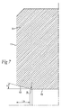
締まりばめ工程の際に駆動シャフト1をローラリング2に挿入することを容易にするために、ローラリングの内部リング3の個々の端面11に隣接する円錐形表面12が形成され(図7参照)、この円錐形表面は、半径がRである半径移行部を介して、内部リングの内部円筒形表面10に変形する。この例では、円錐形表面12の円錐角αは15°(2xα=30°)になり、この表面の軸線方向拡張部又は長さL5は、少なくとも5mmになり、適切には少なくとも10mmであるべきである。ローラリングの雌型の円錐形表面12を駆動シャフトの外表面6に隣接した雄形状の円錐表面と結合させることも実現可能である。
In order to facilitate the insertion of the
上述の具体例では、施された締まりばめ結合の締めしろは、駆動シャフトの直径の0.08%(0.16/200)になる。この締めしろのサイズは、ローラ寸法及び所望のトルクに応じて変更することができるものの、いずれにせよ、少なくとも0.01%、適切には0.05%、さらに適切には0.07%となるべきである。他方では、この締めしろのサイズは、ローラリングでの有害な応力現象のリスクを適切に防ぐために、0.12%よりも大きくなるべきではない。有利には、接合作用は、0.07〜0.10%の範囲内の締めしろによってもたらされる。 In the above example, the interference of the applied interference fit is 0.08% (0.16 / 200) of the drive shaft diameter. The size of this interference can be varied depending on the roller dimensions and the desired torque, but in any case at least 0.01%, suitably 0.05%, more suitably 0.07%. Should be. On the other hand, the size of this interference should not be greater than 0.12% in order to adequately prevent the risk of harmful stress phenomena in the roller ring. Advantageously, the joining action is provided by an interference in the range of 0.07 to 0.10%.
本発明の本質的な利点は、このローラの複合ローラリングを、いかなる機械的なロック手段又は結合手段なしに、信頼性のある容易なやり方で駆動シャフトに対して回転方向に固定することができることにある。さらに、駆動シャフトの外表面に沿った利用可能なスペースに侵入するどのような結合手段もないという理由から、最善のやり方で事実上のローラの幅を利用することができる。さらに、複雑でありかつコストを上昇させる加工作用なしにローラの2つの主構成要素を製造することができる。本質的に、すべての所望のチップ除去加工を旋削の形でもたらすことができるからである。言い換えれば、2つの構成要素のブランクを、互いに異なる機械加工部署同士の間で移動させる必要がないからである。さらに、機械的な結合手段、具体的には溝、孔、皿穴などの形状をした雌形状の手段がないことにより、構成要素のうちのいずれもが不必要に脆弱にならない。それと共に、これらの要因は、ローラの製造の総コストを減少させることができることを意味する。ローラの構成要素の数を絶対的に最小に減少させて、ローラミルが作用しているときに、さらに反対に作用しているときに、故障や活動停止等のリスクを減少させたからである。 An essential advantage of the present invention is that the composite roller ring of this roller can be fixed in a rotational direction relative to the drive shaft in a reliable and easy manner without any mechanical locking or coupling means. It is in. Furthermore, the effective roller width can be utilized in the best way because there is no coupling means to penetrate the available space along the outer surface of the drive shaft. Furthermore, the two main components of the roller can be manufactured without complicated and costly processing action. In essence, all desired chip removal operations can be effected in the form of turning. In other words, it is not necessary to move the two component blanks between different machining departments. Furthermore, the absence of mechanical coupling means, specifically female shaped means such as grooves, holes, countersinks, etc., prevents any of the components from becoming unnecessarily fragile. Together, these factors mean that the total cost of manufacturing the roller can be reduced. This is because the number of roller components has been reduced to an absolute minimum to reduce the risk of failure, outage, etc., when the roller mill is operating, or even the other way around.
本発明は、上述のような実施形態及び図面に示されているような実施形態のみに制限されない。したがって、2つ又は複数のローラリングを有する駆動シャフトを装備することが実現可能であり、これらのローラリングは個々に1及び複数の超硬合金リングを含んでもよい。さらに、個々のローラリングの締まりばめは、駆動シャフトを冷却すること以外に別のやり方によって実施されてもよい。したがって、駆動シャフトは、ローラリングがその内部を拡げるために加熱されると同時に、室温を維持してもよい。駆動シャフトを冷却すると共にローラリングを加熱することも実現可能である。結論として、本発明によれば、この取り付け方法を、新しいローラの製造にだけではなく使用済みのローラの修復にも適用することができることが、指摘されるべきである。よって、ローラの2つの構成要素のうちの一方が破損した又は磨耗した場合に、締まりばめ接合の分離の後に、さらに厳密には新しい又は修復された構成要素に対して固く収縮することによって、他方の構成要素を再利用することができる。駆動シャフトの外表面とローラリングの内面との間で完全な表面接触をする締まりばめを提供することが好ましいものの、必要とされるならば、部分的な表面接触で満足することも実現可能である。 The present invention is not limited to the embodiment as described above and the embodiment as shown in the drawings. It is therefore feasible to equip a drive shaft with two or more roller rings, which may individually comprise one and several cemented carbide rings. Furthermore, the interference fit of the individual roller rings may be implemented in other ways besides cooling the drive shaft. Thus, the drive shaft may be maintained at room temperature while the roller ring is heated to expand its interior. It is also feasible to cool the drive shaft and heat the roller ring. In conclusion, it should be pointed out that according to the invention, this mounting method can be applied not only to the production of new rollers but also to the repair of used rollers. Thus, if one of the two components of the roller breaks or wears, after separation of the interference fit joint, more strictly, by tightly shrinking against the new or repaired component, The other component can be reused. While it is desirable to provide an interference fit that provides full surface contact between the outer surface of the drive shaft and the inner surface of the roller ring, it is feasible to be satisfied with partial surface contact if required. It is.
Claims (5)
ローラリングが、硬い材料から作成される外部リング(4)と、外部リングと同軸であると共により延性のある材料から作成される内部リング(3)とを含み、
内部リングが、一定の内径(ID)を有する円筒形の内面(10)を含み、かつ一方では冶金的なやり方で外部リング(4)に永続的に結合され、他方では、駆動シャフトから外部リング(4)にトルクを伝達するために、駆動シャフト(1)と回転方向に固く接続されている、
ローラにおいて、
駆動シャフト(1)とローラリング(2)との間における、回転方向に固い結合作用は、締りばめ接合のみからなり、
この締りばめ接合は、駆動シャフトの外表面(6)と内部リングの内面(10)との間で行われ、駆動シャフト(1)の外径(OD1)の少なくとも0.01%の締めしろを有する、
ローラ。 On the one hand, it comprises a drive shaft (1) having a cylindrical outer surface (6) having a constant outer diameter (OD1) and a constant length (L3), and on the other hand a shorter roller ring (2). Laura,
The roller ring comprises an outer ring (4) made from a hard material and an inner ring (3) made from a more ductile material that is coaxial with the outer ring;
The inner ring includes a cylindrical inner surface (10) having a constant inner diameter (ID) and, on the one hand, is permanently coupled to the outer ring (4) in a metallurgical manner, on the other hand from the drive shaft to the outer ring. In order to transmit torque to (4), it is firmly connected to the drive shaft (1) in the rotational direction,
In Laura
The hard coupling action in the rotational direction between the drive shaft (1) and the roller ring (2) consists only of an interference fit joint,
This interference fit is performed between the outer surface (6) of the drive shaft and the inner surface (10) of the inner ring, and is tightened to at least 0.01% of the outer diameter (OD1) of the drive shaft (1). Having
roller.
請求項1に記載のローラ。 The interference of the interference fit joint is at least 0.05% of the outer diameter (OD1) of the drive shaft (1).
The roller according to claim 1.
請求項1又は2に記載のローラ。 The interference of the interference fit joint is at least 0.07% of the outer diameter (OD1) of the drive shaft (1).
The roller according to claim 1 or 2.
この円錐形表面が、半径移行部(R)を介して、内部リングの内面(10)に変形する、
請求項1〜3のいずれか1項に記載のローラ。 A conical surface (12) is formed adjacent to the end face (11) of the inner ring (3) of the roller ring (2);
This conical surface deforms via the radius transition (R) to the inner surface (10) of the inner ring,
The roller according to any one of claims 1 to 3.
ローラリングが、硬い材料から作成される外部リングと、外部リングと同軸であると共により延性のある材料から作成される内部リングとを含み、
内部リングが、一定の直径を有する円筒形の内面を含み、かつ一方では冶金的なやり方で外部リングに永続的に結合され、他方では、駆動シャフトから外部リングにトルクを伝達するために、駆動シャフトと回転方向に固く接続されている、
ローラを組立てる方法において、
駆動シャフトとローラリングとの温度にそれぞれ差異を設ける段階と、
駆動シャフトをローラリングに挿入する段階と、
温度を均一化しつつ、回転方向に固い結合作用のみを形成すると共に駆動シャフトの外径の少なくとも0.01%の締めしろを有する締りばめ接合を行う段階と、
によって特徴付けられた、
ローラを組立てる方法。 A method of assembling a roller of the type comprising a drive shaft with a cylindrical outer surface having a constant diameter and a constant length on the one hand and a shorter roller ring on the other hand,
The roller ring includes an outer ring made of a hard material and an inner ring made of a material that is coaxial with the outer ring and is more ductile;
The inner ring includes a cylindrical inner surface with a constant diameter, and on the one hand is permanently coupled to the outer ring in a metallurgical manner, and on the other hand to drive torque from the drive shaft to the outer ring Rigidly connected to the shaft in the direction of rotation,
In the method of assembling the roller,
Providing a difference in temperature between the drive shaft and the roller ring,
Inserting the drive shaft into the roller ring;
Performing an interference fit joint that forms only a rigid coupling action in the rotational direction while equalizing the temperature and has an interference of at least 0.01% of the outer diameter of the drive shaft;
Characterized by,
How to assemble a roller.
Applications Claiming Priority (3)
| Application Number | Priority Date | Filing Date | Title |
|---|---|---|---|
| SE0900325A SE533591C2 (en) | 2009-03-12 | 2009-03-12 | Roller comprising a drive shaft and a roller ring |
| SE0900325-2 | 2009-03-12 | ||
| PCT/SE2010/050197 WO2010104448A1 (en) | 2009-03-12 | 2010-02-19 | A roller comprising a drive shaft and a roller ring, as well as a method for assembling such a roller |
Publications (2)
| Publication Number | Publication Date |
|---|---|
| JP2012520179A true JP2012520179A (en) | 2012-09-06 |
| JP2012520179A5 JP2012520179A5 (en) | 2013-02-14 |
Family
ID=42728563
Family Applications (1)
| Application Number | Title | Priority Date | Filing Date |
|---|---|---|---|
| JP2011553982A Pending JP2012520179A (en) | 2009-03-12 | 2010-02-19 | Roller with drive shaft and roller ring and method for assembling such a roller |
Country Status (11)
| Country | Link |
|---|---|
| US (1) | US20120028772A1 (en) |
| EP (1) | EP2406020A4 (en) |
| JP (1) | JP2012520179A (en) |
| KR (1) | KR20110128864A (en) |
| CN (1) | CN102348515A (en) |
| BR (1) | BRPI1009351A2 (en) |
| MX (1) | MX2011009408A (en) |
| RU (1) | RU2011141264A (en) |
| SE (1) | SE533591C2 (en) |
| WO (1) | WO2010104448A1 (en) |
| ZA (1) | ZA201106514B (en) |
Cited By (2)
| Publication number | Priority date | Publication date | Assignee | Title |
|---|---|---|---|---|
| JP2011206819A (en) * | 2010-03-30 | 2011-10-20 | Mitsubishi Materials Corp | Rolling roll and method for reutilizing rolling roll |
| CN114799729A (en) * | 2022-03-18 | 2022-07-29 | 宜昌船舶柴油机有限公司 | Assembly tool and method for reinforcing back ring of cylinder sleeve of large-cylinder-diameter low-speed diesel engine |
Families Citing this family (3)
| Publication number | Priority date | Publication date | Assignee | Title |
|---|---|---|---|---|
| CN110125175B (en) * | 2019-05-30 | 2020-07-03 | 江苏豪泽工业炉有限公司 | Combined roller |
| CN111589874B (en) * | 2020-05-27 | 2022-05-20 | 陈歌 | Combined roller manufactured in environment-friendly mode and manufacturing method thereof |
| CN111842496A (en) * | 2020-07-21 | 2020-10-30 | 刘欣鑫 | Chilled cast iron roller |
Citations (2)
| Publication number | Priority date | Publication date | Assignee | Title |
|---|---|---|---|---|
| JPS58128525A (en) * | 1982-01-27 | 1983-08-01 | Sumitomo Metal Ind Ltd | Manufacture of composite roll |
| JPH04228212A (en) * | 1990-04-12 | 1992-08-18 | United Eng Inc | Assembling method of roll of rolling mill and deformable roll |
Family Cites Families (25)
| Publication number | Priority date | Publication date | Assignee | Title |
|---|---|---|---|---|
| US21039A (en) * | 1858-07-27 | Improvement in making steel rollers | ||
| GB191121154A (en) * | 1911-09-25 | 1912-09-25 | Ernest James Gerrard | Improvements in Rolling Mills for Rolling Sheets of Metal. |
| US1427063A (en) * | 1919-12-01 | 1922-08-22 | Canda Ferdinand Mora | Roll for rolling mills |
| DE425268C (en) * | 1924-06-13 | 1926-02-13 | Theodor Weymerskirch | Cast iron roller with steel axle |
| FR612158A (en) * | 1926-01-12 | 1926-10-19 | Cast iron cylinders with steel shaft | |
| US3451903A (en) * | 1965-04-09 | 1969-06-24 | Mitsubishi Heavy Ind Ltd | Conductor roll and method of making the same |
| SE322749B (en) * | 1966-02-09 | 1970-04-20 | Sandvikens Jernverks Ab | |
| DE1627759A1 (en) * | 1966-09-19 | 1970-09-24 | Mitsubishi Steel Mfg | Built-up roll for quadruple mills and process for their production |
| US3577619A (en) * | 1969-05-12 | 1971-05-04 | Sandvikens Jernverks Ab | Method of manufacturing composite hardmetal rolls |
| US3827134A (en) * | 1970-08-06 | 1974-08-06 | Bethlehem Steel Corp | Apparatus for shrinking collars on a shaft |
| US3725994A (en) * | 1970-08-06 | 1973-04-10 | Bethlehem Steel Corp | Method of shrinking collars on a shaft |
| US3711913A (en) * | 1971-03-24 | 1973-01-23 | V Galeone | Method of making a composite roll |
| DE2315090C3 (en) * | 1973-03-27 | 1980-01-24 | Alex Prof. Dr. 5000 Koeln Troost | Method for producing a composite body |
| SU668730A1 (en) * | 1975-06-27 | 1979-07-10 | Московский Ордена Трудового Красного Знамени Институт Стали И Сплавов | Composite roll |
| JPS56151149A (en) * | 1980-04-23 | 1981-11-24 | Kubota Ltd | Assembling type roll for continuous casting of slab |
| US5044056A (en) * | 1988-12-13 | 1991-09-03 | Sandvik Ab | Roll ring comprising a ring of cemented carbide metallurgically bonded to a cast iron body |
| JPH03138010A (en) * | 1989-10-23 | 1991-06-12 | Fuji Kogyosho:Kk | Manufacture of roll for rolling steel tube |
| SE9100405D0 (en) * | 1991-02-11 | 1991-02-11 | Sandvik Ab | ROLLING, COMPOSITION OF HEAVY METAL AND CASTING IRON, AND SUITABLE FOR PREPARATION OF THE SAME |
| US5248289A (en) * | 1989-12-13 | 1993-09-28 | Sandvik Ab | Cast iron roll with one or more cemented carbide roll rings metallurgically bonded thereto |
| US5111930A (en) * | 1991-03-18 | 1992-05-12 | International Rolling Mill Consultants, Inc. | Non-warping table rolls |
| JPH05154514A (en) * | 1991-12-05 | 1993-06-22 | Sumitomo Metal Ind Ltd | Grooved roll for rolling and manufacture of its roll body |
| DE9309450U1 (en) * | 1993-06-25 | 1993-08-26 | Saar Hartmetall & Werkzeuge | Composite body, consisting of materials with different thermal and mechanical properties |
| KR960007486B1 (en) * | 1994-03-05 | 1996-06-05 | 대한중석 주식회사 | Rolling roller |
| KR100680282B1 (en) * | 2005-11-02 | 2007-02-08 | 한국과학기술연구원 | Shrink fitting including deformation |
| CN101069895A (en) * | 2007-06-11 | 2007-11-14 | 浙江省冶金研究院有限公司 | Glue-jointed hardalloy composite roller ring |
-
2009
- 2009-03-12 SE SE0900325A patent/SE533591C2/en not_active IP Right Cessation
-
2010
- 2010-02-19 US US13/254,878 patent/US20120028772A1/en not_active Abandoned
- 2010-02-19 RU RU2011141264/02A patent/RU2011141264A/en not_active Application Discontinuation
- 2010-02-19 KR KR1020117021332A patent/KR20110128864A/en not_active Application Discontinuation
- 2010-02-19 EP EP10751084.4A patent/EP2406020A4/en not_active Withdrawn
- 2010-02-19 JP JP2011553982A patent/JP2012520179A/en active Pending
- 2010-02-19 CN CN2010800118732A patent/CN102348515A/en active Pending
- 2010-02-19 WO PCT/SE2010/050197 patent/WO2010104448A1/en active Application Filing
- 2010-02-19 BR BRPI1009351A patent/BRPI1009351A2/en not_active IP Right Cessation
- 2010-02-19 MX MX2011009408A patent/MX2011009408A/en not_active Application Discontinuation
-
2011
- 2011-09-06 ZA ZA2011/06514A patent/ZA201106514B/en unknown
Patent Citations (2)
| Publication number | Priority date | Publication date | Assignee | Title |
|---|---|---|---|---|
| JPS58128525A (en) * | 1982-01-27 | 1983-08-01 | Sumitomo Metal Ind Ltd | Manufacture of composite roll |
| JPH04228212A (en) * | 1990-04-12 | 1992-08-18 | United Eng Inc | Assembling method of roll of rolling mill and deformable roll |
Cited By (3)
| Publication number | Priority date | Publication date | Assignee | Title |
|---|---|---|---|---|
| JP2011206819A (en) * | 2010-03-30 | 2011-10-20 | Mitsubishi Materials Corp | Rolling roll and method for reutilizing rolling roll |
| CN114799729A (en) * | 2022-03-18 | 2022-07-29 | 宜昌船舶柴油机有限公司 | Assembly tool and method for reinforcing back ring of cylinder sleeve of large-cylinder-diameter low-speed diesel engine |
| CN114799729B (en) * | 2022-03-18 | 2024-03-08 | 宜昌船舶柴油机有限公司 | Assembly tool and method for reinforcing back ring of cylinder liner of large-diameter low-speed diesel engine |
Also Published As
| Publication number | Publication date |
|---|---|
| MX2011009408A (en) | 2011-09-27 |
| EP2406020A4 (en) | 2013-04-24 |
| WO2010104448A1 (en) | 2010-09-16 |
| US20120028772A1 (en) | 2012-02-02 |
| SE0900325A1 (en) | 2010-09-13 |
| BRPI1009351A2 (en) | 2016-03-08 |
| RU2011141264A (en) | 2013-04-20 |
| KR20110128864A (en) | 2011-11-30 |
| EP2406020A1 (en) | 2012-01-18 |
| SE533591C2 (en) | 2010-11-02 |
| ZA201106514B (en) | 2014-02-26 |
| CN102348515A (en) | 2012-02-08 |
Similar Documents
| Publication | Publication Date | Title |
|---|---|---|
| JP2012520179A (en) | Roller with drive shaft and roller ring and method for assembling such a roller | |
| EP2220293B1 (en) | Thermo roll | |
| US7543691B2 (en) | Brake rotor assembly | |
| EP1802878B1 (en) | Method and apparatus for coupling components | |
| KR20150087198A (en) | Turbocharger impeller screwed onto shaft with arrangement for accommodating thermal dilatation | |
| JP5259930B2 (en) | Roll, roll ring and method in the production of such a roll | |
| US8261767B1 (en) | Powdered metal inlay | |
| US6557654B1 (en) | Drill pipe having a journal formed thereon | |
| JP4923047B2 (en) | Backup roll for rolling mill | |
| KR101667466B1 (en) | Shaft-to-roller attachment for clinker grinder roller | |
| CN101389416B (en) | Support roll for a rolling mill and its manufacture method | |
| AU2002358749B2 (en) | Casting roll and a method for producing a casting roll | |
| US9868141B2 (en) | Workpiece-shaping tool assembly | |
| PL177884B1 (en) | Continuous casting cylinder for continuously casting metals on a single cylinder or between two cylindrical surfaces | |
| KR101093379B1 (en) | Rolling mill and roll thereof | |
| JP2012504213A (en) | Universal joint structure for cardan shaft | |
| JP2010281431A (en) | Shaft coupling and constant velocity universal joint | |
| CN212803980U (en) | Oldham coupling | |
| KR20040081980A (en) | Disk roll for rolling | |
| KR101319188B1 (en) | Extrusion die | |
| JPH0243522Y2 (en) | ||
| JP4340989B2 (en) | Cemented carbide composite roll | |
| Roy et al. | Development of an ingenious composite roll system for merchant mill | |
| JPS60166109A (en) | Built-up type rolling roll with fitting joint | |
| JPS591128B2 (en) | Assembly roll for rolling |
Legal Events
| Date | Code | Title | Description |
|---|---|---|---|
| A521 | Written amendment |
Free format text: JAPANESE INTERMEDIATE CODE: A523 Effective date: 20121219 |
|
| A621 | Written request for application examination |
Free format text: JAPANESE INTERMEDIATE CODE: A621 Effective date: 20121219 |
|
| A02 | Decision of refusal |
Free format text: JAPANESE INTERMEDIATE CODE: A02 Effective date: 20140715 |