JP2012506809A - Trigger type stroke actuator for safety system - Google Patents
Trigger type stroke actuator for safety system Download PDFInfo
- Publication number
- JP2012506809A JP2012506809A JP2011532690A JP2011532690A JP2012506809A JP 2012506809 A JP2012506809 A JP 2012506809A JP 2011532690 A JP2011532690 A JP 2011532690A JP 2011532690 A JP2011532690 A JP 2011532690A JP 2012506809 A JP2012506809 A JP 2012506809A
- Authority
- JP
- Japan
- Prior art keywords
- piston
- latch
- actuator
- actuator according
- propulsion means
- Prior art date
- Legal status (The legal status is an assumption and is not a legal conclusion. Google has not performed a legal analysis and makes no representation as to the accuracy of the status listed.)
- Granted
Links
Images


Classifications
-
- F—MECHANICAL ENGINEERING; LIGHTING; HEATING; WEAPONS; BLASTING
- F15—FLUID-PRESSURE ACTUATORS; HYDRAULICS OR PNEUMATICS IN GENERAL
- F15B—SYSTEMS ACTING BY MEANS OF FLUIDS IN GENERAL; FLUID-PRESSURE ACTUATORS, e.g. SERVOMOTORS; DETAILS OF FLUID-PRESSURE SYSTEMS, NOT OTHERWISE PROVIDED FOR
- F15B15/00—Fluid-actuated devices for displacing a member from one position to another; Gearing associated therewith
- F15B15/19—Pyrotechnical actuators
-
- F—MECHANICAL ENGINEERING; LIGHTING; HEATING; WEAPONS; BLASTING
- F15—FLUID-PRESSURE ACTUATORS; HYDRAULICS OR PNEUMATICS IN GENERAL
- F15B—SYSTEMS ACTING BY MEANS OF FLUIDS IN GENERAL; FLUID-PRESSURE ACTUATORS, e.g. SERVOMOTORS; DETAILS OF FLUID-PRESSURE SYSTEMS, NOT OTHERWISE PROVIDED FOR
- F15B15/00—Fluid-actuated devices for displacing a member from one position to another; Gearing associated therewith
- F15B15/02—Mechanical layout characterised by the means for converting the movement of the fluid-actuated element into movement of the finally-operated member
- F15B15/04—Mechanical layout characterised by the means for converting the movement of the fluid-actuated element into movement of the finally-operated member with oscillating cylinder
-
- F—MECHANICAL ENGINEERING; LIGHTING; HEATING; WEAPONS; BLASTING
- F15—FLUID-PRESSURE ACTUATORS; HYDRAULICS OR PNEUMATICS IN GENERAL
- F15B—SYSTEMS ACTING BY MEANS OF FLUIDS IN GENERAL; FLUID-PRESSURE ACTUATORS, e.g. SERVOMOTORS; DETAILS OF FLUID-PRESSURE SYSTEMS, NOT OTHERWISE PROVIDED FOR
- F15B15/00—Fluid-actuated devices for displacing a member from one position to another; Gearing associated therewith
- F15B15/20—Other details, e.g. assembly with regulating devices
- F15B15/26—Locking mechanisms
- F15B15/261—Locking mechanisms using positive interengagement, e.g. balls and grooves, for locking in the end positions
-
- F—MECHANICAL ENGINEERING; LIGHTING; HEATING; WEAPONS; BLASTING
- F42—AMMUNITION; BLASTING
- F42B—EXPLOSIVE CHARGES, e.g. FOR BLASTING, FIREWORKS, AMMUNITION
- F42B3/00—Blasting cartridges, i.e. case and explosive
- F42B3/006—Explosive bolts; Explosive actuators
-
- B—PERFORMING OPERATIONS; TRANSPORTING
- B60—VEHICLES IN GENERAL
- B60R—VEHICLES, VEHICLE FITTINGS, OR VEHICLE PARTS, NOT OTHERWISE PROVIDED FOR
- B60R21/00—Arrangements or fittings on vehicles for protecting or preventing injuries to occupants or pedestrians in case of accidents or other traffic risks
- B60R21/34—Protecting non-occupants of a vehicle, e.g. pedestrians
- B60R21/38—Protecting non-occupants of a vehicle, e.g. pedestrians using means for lifting bonnets
Abstract
トリガー前は初期位置に静止保持されるピストンを備えるトリガー型ストロークアクチュエータ。ピストン(13)は、推進手段(15)とロック機構(19)とに対向して本体(12)内に設置され、このロック機構(19)は、ラッチ(30)と、ピストンの周縁部に取り付けられており、内側当接部と係合するフック(25)を有する、少なくとも1つの可撓性の舌片(23)とを含み、このラッチは、トリガー開始時に移動される。
【選択図】図1A trigger-type stroke actuator with a piston that is held stationary at the initial position before the trigger. The piston (13) is installed in the main body (12) so as to face the propulsion means (15) and the lock mechanism (19). The lock mechanism (19) is connected to the latch (30) and the peripheral portion of the piston. At least one flexible tongue (23) attached and having a hook (25) engaging the inner abutment, the latch being moved at the start of the trigger.
[Selection] Figure 1
Description
本発明は、トリガー型ストロークアクチュエータに関し、詳細には、自動車両の安全システム、より詳細には、自動車両との正面衝突の際にそのボンネットを持ち上げることで歩行者を保護することができるシステムに組み込まれる、アクチュエータに関する。本発明はそのようなアクチュエータの改良に関し、その改良とは、アクチュエータのロッドに連結されている機械部品が定位置に堅固に保持されるようにピストンをその初期位置にロックし、その一方で、アクチュエータがトリガーされた場合には、いかなる追加の命令も必要とせずに、ピストンをロック解除可能にすることにある。 The present invention relates to a trigger type stroke actuator, and more particularly, to a safety system for an automatic vehicle, and more specifically, to a system capable of protecting a pedestrian by lifting its bonnet at the time of a frontal collision with the automatic vehicle. It relates to an actuator to be incorporated. The present invention relates to an improvement of such an actuator, which locks the piston in its initial position so that the mechanical part connected to the rod of the actuator is firmly held in place, It is to allow the piston to be unlocked without requiring any additional command if the actuator is triggered.
自動車両に衝突されたときに歩行者を保護するための数多くの安全システムが知られている。たとえば、仏国特許出願公開第2878212号の文献では、衝突のときに素早く自動車両のボンネットを持ち上げることを可能にする機構を備えるシステムが記載されている。衝突の際には、歩行者の頭部が車両のボンネットに打ち付けられることがしばしばある。この衝撃により、ボンネットが変形する。変形の度合いがある程度を超えると、ボンネットは、エンジンおよびその周辺の全ての剛性部品に接触する。歩行者の頭部が最も激しく減速されるのはこの瞬間であり、これにより、重大な結果が生じ得る。そのため、上述の文献に記載のシステムは、歩行者、特には歩行者の頭部が、ボンネットの変形後にエンジンに打ち付けられることを回避するように、ボンネットを突如としてある高さだけ持ち上げるように設計されている。ボンネットは、自動車両の前部に蝶番式に固定されたままで、その後部すなわちフロントガラス側が持ち上げられる。 Numerous safety systems are known for protecting pedestrians when impacted by motor vehicles. For example, document FR 2 878 212 describes a system with a mechanism that makes it possible to quickly lift the hood of a motor vehicle in the event of a collision. During a collision, the pedestrian's head is often struck against the hood of the vehicle. The bonnet is deformed by this impact. When the degree of deformation exceeds a certain level, the bonnet contacts the engine and all the rigid parts around it. It is at this moment that the pedestrian's head is most severely decelerated, which can have serious consequences. Therefore, the system described in the above-mentioned document is designed to suddenly lift the bonnet by a certain height so as to avoid the pedestrian, especially the head of the pedestrian, from hitting the engine after the deformation of the bonnet. Has been. The bonnet is hingedly fixed to the front part of the motor vehicle, and the rear part, that is, the windshield side is lifted.
したがって、このような安全装置は、適切な検知手段によって遅れずに作動されることを前提に、差し迫る衝突を検知後30ミリセカンド(ms)程度という極めて短い時間内に、ボンネットを少なくとも80ミリメートル(mm)だけ持ち上げるように働く。 Therefore, on the assumption that such a safety device is operated without delay by appropriate detection means, the bonnet is at least 80 millimeters within a very short time of about 30 milliseconds (ms) after detecting an impending collision. It works to lift only (mm).
この種の安全システムの動作、とりわけアクチュエータの動作を改善しようとする数多くの改良が記載されてきている。特には、衝撃の際に速度を鈍らせつつボンネットを戻すことを追求する改良、衝突が起こっていないのにトリガーされてしまった後にボンネットを再配置する可能性を追求する改良、アクチュエータが連結されている機構が破損するのを避けるためにトリガーストロークの終端でピストンの運動を減衰させることを追求する改良、が挙げられる。 Numerous improvements have been described that seek to improve the operation of this type of safety system, especially the operation of the actuator. In particular, an improvement that seeks to return the bonnet while reducing the speed in the event of an impact, an improvement that pursues the possibility of repositioning the bonnet after being triggered when no collision has occurred, and an actuator are connected An improvement that seeks to damp the piston movement at the end of the trigger stroke to avoid damaging the working mechanism.
可能な限り、これらの改良は全て、アクチュエータそのものに組み込むことが望ましい。 As much as possible, all these improvements should be incorporated into the actuator itself.
この方針に沿って、設計者の別の関心事は、アクチュエータのピストンが、(トリガー前は、その初期位置に)適切にロックされていることを確実にすること、および、その結果として、アクチュエータの端部から突出し、ボンネット持ち上げ機構または直接連結の場合はボンネットそのものに連結されたピストンロッドが適切にロックされていることを確実にすることである。このようにロックされることで、安全システムがトリガーされない限り、この機構ひいてはボンネットが強固に保持されるようになる。このロック機能をアクチュエータそのものの本体内に組み込むことにより、全体の寸法縮小および原価低減につながる。 In line with this policy, another concern of the designer is to ensure that the actuator piston is properly locked (in its initial position before triggering) and, as a result, the actuator In the case of a bonnet lifting mechanism or direct connection, it is ensured that the piston rod connected to the bonnet itself is properly locked. By being locked in this manner, the mechanism and thus the bonnet are firmly held unless the safety system is triggered. By incorporating this lock function into the main body of the actuator itself, the overall size and cost can be reduced.
たとえば、国際公開第2005/085014号の文献には、アクチュエータ本体の壁に形成された溝内に周方向に配置された複数のボールから構成されるロック装置を備えるアクチュエータが記載されている。これらのボールは、バネによりピストンに連結された中央のフィンガによって径方向に保持されている。これらのボールは、アクチュエータのピストンに固定されている。この位置では、アクチュエータはロックされている。アクチュエータを動作させるには、電磁石により駆動される打撃部がフィンガを押圧し、このフィンガがピストンに向かって移動し、それにより、ボールが周方向の溝から解放されてピストンがロック解除される。その後、圧力を受けたガスがピストンに押し当たり、アクチュエータを展開させる。アクチュエータロッドに戻り作用をかけることにより、アクチュエータを再ロックすることが可能である。このような装置は、アクチュエータをロック解除するためだけに特別な制御部材(電磁石および打撃部)を必要とし、その結果、この装置が複雑かつ高価になっているという欠点がある。さらに、ロック手段として複数のボールを使用することで、(特にその配置場所のために)多くの機械加工部分が必要となり、それにより、アクチュエータの組み立てが複雑になり、ロボットによる組立ラインへの適合性が低くなる。 For example, International Publication No. 2005/085014 describes an actuator including a locking device composed of a plurality of balls arranged in a circumferential direction in a groove formed in a wall of an actuator body. These balls are held radially by a central finger connected to the piston by a spring. These balls are fixed to the piston of the actuator. In this position, the actuator is locked. To operate the actuator, the striking part driven by the electromagnet presses the finger, which moves toward the piston, thereby releasing the ball from the circumferential groove and unlocking the piston. Thereafter, the pressured gas presses against the piston and deploys the actuator. By applying a return action to the actuator rod, it is possible to relock the actuator. Such a device has the disadvantage that it requires a special control member (electromagnet and striking part) only to unlock the actuator, resulting in a complicated and expensive device. In addition, the use of multiple balls as locking means requires a lot of machined parts (especially due to their location), which complicates the assembly of the actuator and adapts to the assembly line by the robot. Low.
本発明は、これらの欠点全てを回避することができる別の解決策、すなわち、組み立てが容易で、安価で、特別な制御部材に頼らずともアクチュエータを動作可能にロック解除可能で、アクチュエータロッドに戻り作用をかけることで選択的に再ロック可能な、内部にロック装置を有するアクチュエータを提案する。 The present invention provides another solution that can avoid all of these drawbacks, i.e., easy to assemble, inexpensive, operably unlocking the actuator without resorting to special control members, An actuator having an internal locking device that can be selectively re-locked by applying a return action is proposed.
より正確には、本発明は、本体と、前記本体中を移動可能な作動ピストンと、前記ピストンを推進させる推進手段と、内側当接部と協働して前記ピストンを所定位置に静止保持し、前記ピストンをロックするロック機構とを備える、安全システム用のトリガー型ストロークアクチュエータであって、前記ロック機構が、円筒形のワッシャの形状で前記ピストンを解除するために前記アクチュエータの前記推進手段によって前記ピストンに向かって移動可能なラッチと、前記ピストンの前記推進手段近傍の周縁部に取り付けられており、前記内側当接部と係合するフックを含む、少なくとも1つの可撓性の舌片とを備えていること、および、前記ラッチが、前記内側当接部と係合している前記フックに接して後退している後方位置と、前記後方位置よりも前記ピストンの横断壁の近くであって、前記フックから離れた前方位置との間を移動可能であることを特徴とする、アクチュエータを提供する。 More precisely, the present invention cooperates with a main body, an actuating piston movable in the main body, a propulsion means for propelling the piston, and an inner abutting portion to hold the piston stationary at a predetermined position. A trigger-type stroke actuator for a safety system comprising a locking mechanism for locking the piston, wherein the locking mechanism is in the form of a cylindrical washer by the propulsion means of the actuator to release the piston At least one flexible tongue including a latch movable toward the piston and a hook attached to a peripheral edge of the piston near the propulsion means and engaging the inner abutment; A rear position where the latch is retracted in contact with the hook engaged with the inner abutting portion, and the rear A near transverse wall of the piston than location, characterized in that it is movable between a forward position away from the hook, to provide an actuator.
一実施形態では、前記ロック機構が、ピストンの移動軸に関して対称に配置されラッチの移動のためのガイドを形成する、少なくとも2つの舌片を有する。たとえば、これらの舌片は、円筒の一部分の形状をした内面を有していてもよく、厚みのあるワッシャの形状をした前記ラッチは、作動時に、これらの舌片がアクチュエータ本体の内側方向に引き込まれる前に、これらの2つの面の間を摺動することができる。 In one embodiment, the locking mechanism has at least two tongues arranged symmetrically with respect to the axis of movement of the piston and forming a guide for movement of the latch. For example, the tongues may have an inner surface in the shape of a portion of a cylinder, and the latch in the form of a thick washer will cause the tongues to be inward of the actuator body when activated. Before being retracted, it is possible to slide between these two surfaces.
好ましい実施形態では、ロック機構が4つの舌片を備え、それにより、ラッチの周縁部のまわりのガスの流動域(flow section)を制限する。 In a preferred embodiment, the locking mechanism comprises four tongues, thereby restricting the gas flow section around the periphery of the latch.
前記推進手段は、本体内に収容された火薬式発生器により構成されることが好ましい。 Preferably, the propulsion means is constituted by an explosive generator accommodated in the main body.
発生器がトリガーされると、発生器はまずラッチを移動させ、その結果、ピストンそのものを移動させる前にピストンをロック解除する。このように、ロック解除を開始するのが非常に簡単であり、いかなる追加の費用も伴わない。 When the generator is triggered, the generator first moves the latch so that it unlocks the piston before moving the piston itself. In this way, unlocking is very easy to initiate and without any additional cost.
一実施形態では、このような可撓性の舌片が薄肉部を含む。 In one embodiment, such a flexible tongue includes a thin portion.
このピストンは、スカート、たとえば円筒形のスカートを含み、一または複数の可撓性の舌片は、そこからの一または複数の延長部となっていてもよい。スカートの端壁は、ロック解除ストロークの終端でラッチが接近して押圧する当接部を構成している。 The piston includes a skirt, such as a cylindrical skirt, and the one or more flexible tongues may be one or more extensions therefrom. The end wall of the skirt forms an abutting portion where the latch approaches and presses at the end of the unlocking stroke.
この当接部が円錐台または同様の形状であれば、ロック解除ストロークの終端で、ラッチはピストンのスカートの端部に当たって止まったままになる。この場合、システムは不可逆的である。 If this abutment is a truncated cone or similar shape, at the end of the unlocking stroke, the latch rests against the end of the piston skirt. In this case, the system is irreversible.
対照的に、別の可能な実施形態では、トリガーされた後にピストンが再ロックされることを可能にするために、ラッチとピストンとの間にバネが介在している。 In contrast, in another possible embodiment, a spring is interposed between the latch and the piston to allow the piston to be re-locked after being triggered.
上述の構成は、簡単である点と低原価である点で注目に値する。このアクチュエータを構成する部品の組み立ての最中に、一または複数のフックがアクチュエータの本体内で内側当接部と係合するまで、一または複数の舌片を含むピストンをアクチュエータの本体に直接挿入することができる。この当接部は、単に、ピストンを一の移動方向について保持する、アクチュエータの本体の拡張部と、反対の移動方向についてピストンを保持する、火薬式作動装置の端部とによって構成されてよい。 The configuration described above is notable for its simplicity and low cost. During assembly of the parts that make up this actuator, the piston containing one or more tongues is inserted directly into the actuator body until one or more hooks engage the inner abutment within the actuator body. can do. This abutment may simply consist of an extension of the body of the actuator that holds the piston in one direction of movement and an end of the explosive actuator that holds the piston in the opposite direction of movement.
構成要素の数は、従来技術の装置と比べて少ない。 The number of components is small compared to prior art devices.
純粋に例として示し、添付の図面を参照して行う、本発明の原理によるトリガー型ストロークアクチュエータの複数の実施形態についての以下の記述を参照することで、本発明はよりよく理解され、本発明の他の利点がより明確になる。 The present invention will be better understood and understood by reference to the following description of several embodiments of a triggered stroke actuator according to the principles of the present invention, given purely by way of example and with reference to the accompanying drawings, in which: Other advantages become clearer.
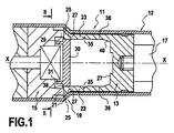
図1から図3を参照すると、ほぼ円筒形の本体12と、本体中を移動可能なアクチュエータピストン13と、一般に火薬式発生器15と称される、火薬によりトリガーされるガス発生器から構成されるピストン推進手段とを備える、本発明によるトリガー型ストロークアクチュエータ11の実施形態が見られる。
Referring to FIGS. 1-3, it comprises a generally
このピストンは、本体の一端から軸方向に突出するロッド17によって延長されている。一例として、このロッドは、自動車両のボンネットを持ち上げるための機構に連結されている。
The piston is extended by a
重要な特徴によると、アクチュエータには、内側当接部21と協働してピストン13を所定位置に静止保持するピストンロック機構19が装着されている。この例では、ロック機構は、ピストンの推進手段側の周縁部に取り付けられた4つの可撓性の舌片23を含む。各舌片23は、内側当接部と係合するフック25を含む。この例では、内側当接部は二重当接部であり、本体の壁の円錐形の肩部27と火薬式発生器15の前方環状端部29とから構成される。各可撓性の舌片のフックは、この二重当接部21によって位置決めされているので、図示のように本体の内周で環状のハウジングに係合している。ピストンはアクチュエータ本体の(大径の)後端から挿入されてもよく、火薬式発生器15を定位置に配置することにより本体内で静止保持されるので、このロック機構の構成により組立が非常に簡単になる。
According to an important feature, the actuator is fitted with a
このロック機構は、(トリガー前は)舌片23の後方で2つのフック25の近傍に位置している、ラッチ30をさらに含む。このラッチ30は、ある程度の厚みがある単純な円筒形のワッシャの形であり、2つの舌片の間に保持されている。ラッチ30は、環状の内側当接部と係合しているフック25の背面に当たって位置している(図1に示す)後方位置と、フックから離れてピストンの横断壁27の近傍で当接状態にある(図3に示す)前方位置との間を移動可能である。このラッチは、具体的には火薬式発生器15の点火によって、このピストンに向かって移動する。つまり、ピストン推進手段は、ピストンを移動可能にすべくロック解除するためにラッチを移動させるようにも働く。
The locking mechanism further includes a
図1から図3の例では、ラッチ30は、トリガーの際にガスの推力をラッチの中心部に向けて伝えるように作用する後方スカート31を有する。
In the example of FIGS. 1-3, the
図示のように、舌片23は、ピストンの移動軸XXに関して対称に、対をなして配置されており、ラッチを移動させるためのガイドを形成する。2つの舌片の内面は、ラッチ30の直径に対応する直径の共通の円筒面上にある(図2)。火薬式発生器15がトリガーされると、ガス圧力がラッチの両側で平衡に達する時間があるまでにラッチが前方に推進されることを理解されたい。
As illustrated, the
ロック機構が舌片を2つだけを有する場合、これらの舌片は同様に軸XXに関して対称である。このような場合、ラッチ周縁部でのガス流動域を減少させるように、ラッチの形状が変更されてよい。ラッチは、たとえば、本体の直径に対応する大径の縁部2つを有してもよい。 If the locking mechanism has only two tongues, these tongues are likewise symmetrical about the axis XX. In such a case, the shape of the latch may be changed so as to reduce the gas flow area at the peripheral edge of the latch. The latch may, for example, have two large diameter edges corresponding to the diameter of the body.
図示のように、各舌片23は、有利には、ピストンがそのストロークに沿って移動している最中に舌片が曲がるのを促進する薄肉部35を含む。この例では、舌片は、前記薄肉部そのものを介してピストンの円筒形の後方スカート36に連結されてよい。図1の例では、ラッチは小さな後方縁部38を含み、これを介して2つのフックの端面と当接する。この後方縁部は、トリガーの際には破壊される。
As shown, each
さらに、ピストンは、ラッチに対向する当接部40を含み、ロック解除ストロークの終端でラッチがこれに押し当てられる。図1から図3の例では、このシステムは意図的に不可逆的である、すなわち、火薬式発生器が点火された後にピストンをその初期位置に再ロックすることはできない。そのため、ロック解除ストロークの終端でラッチが保持されるように、当接部40は、円錐台または同様の形状をしている。
Furthermore, the piston includes an
図4および図5の例では、類似の部材には同じ参照符号が付されており、システムは再ロック可能である。言い換えると、火薬式発生器15が点火された後、またその結果ボンネットが持ち上げられた後で、ピストン13を再ロックすることによりシステムをその初期位置に復帰させることが可能である。これを行うためには、ラッチ30は、フック25と位置合わせされたその開始位置に自動的に復帰可能でなければならない。そのため、バネ42がラッチとピストンの間に介在している。
In the example of FIGS. 4 and 5, similar members are given the same reference numerals and the system is relockable. In other words, it is possible to return the system to its initial position by relocking the
この実施形態では、単に、舌片23の厚みが、それらが連結されたピストンのスカート36の厚みよりも小さいということにより、舌片23に可撓性が付与されている。この厚みの差によって、ラッチ30のためのストローク終端の当接部を構成する、2つの肩部44が画定される。したがって、バネ42は、肩部44とピストンの横断壁27との間に位置する空洞45内で圧縮することができる(図5)。
In this embodiment, the
さらに、これらの可撓性の舌片23は、バネ42からの推力を受けてラッチが押し当てられる後方当接部46を備える。トリガー前は、これらの後方当接部46により、また、バネがこれらの当接部にラッチを押し当てているという事実により、ラッチの位置がこのように決定される。
Further, these
図6および図7は、単一の可撓性の舌片23aが2つの平行な長孔49によってピストン13の筒状のスカート47から切り出されている実施形態を示す。
FIGS. 6 and 7 show an embodiment in which a single
Claims (11)
Applications Claiming Priority (3)
| Application Number | Priority Date | Filing Date | Title |
|---|---|---|---|
| FR0857317A FR2937691B1 (en) | 2008-10-28 | 2008-10-28 | TRAPPED CYLINDER FOR SAFETY SYSTEM |
| FR0857317 | 2008-10-28 | ||
| PCT/FR2009/052009 WO2010049625A1 (en) | 2008-10-28 | 2009-10-21 | Triggered-travel jack for a safety system |
Publications (2)
| Publication Number | Publication Date |
|---|---|
| JP2012506809A true JP2012506809A (en) | 2012-03-22 |
| JP5431488B2 JP5431488B2 (en) | 2014-03-05 |
Family
ID=40791373
Family Applications (1)
| Application Number | Title | Priority Date | Filing Date |
|---|---|---|---|
| JP2011532690A Expired - Fee Related JP5431488B2 (en) | 2008-10-28 | 2009-10-21 | Trigger type stroke actuator for safety system |
Country Status (11)
| Country | Link |
|---|---|
| US (1) | US8813495B2 (en) |
| EP (1) | EP2350464B1 (en) |
| JP (1) | JP5431488B2 (en) |
| KR (1) | KR20110075002A (en) |
| CN (1) | CN102197230B (en) |
| BR (1) | BRPI0920004A2 (en) |
| CA (1) | CA2741821A1 (en) |
| FR (1) | FR2937691B1 (en) |
| MX (1) | MX2011004389A (en) |
| RU (1) | RU2011118853A (en) |
| WO (1) | WO2010049625A1 (en) |
Cited By (3)
| Publication number | Priority date | Publication date | Assignee | Title |
|---|---|---|---|---|
| JP2016020728A (en) * | 2014-07-15 | 2016-02-04 | 豊田合成株式会社 | Actuator |
| JP2017218106A (en) * | 2016-06-10 | 2017-12-14 | 日本化薬株式会社 | Igniter with piston and pyroactuator |
| JP2021536395A (en) * | 2018-09-14 | 2021-12-27 | オートリブ ディベロップメント エービー | Vehicle safety device to provide pedestrian protection |
Families Citing this family (3)
| Publication number | Priority date | Publication date | Assignee | Title |
|---|---|---|---|---|
| CN102367822B (en) * | 2011-10-20 | 2015-09-09 | 大连橡胶塑料机械股份有限公司 | Latch oil cylinder device |
| CN102367823B (en) * | 2011-11-03 | 2014-05-28 | 中航飞机起落架有限责任公司 | Automatically reversible air cylinder device with built-in mechanical lock |
| AT526224B1 (en) * | 2022-07-05 | 2024-02-15 | Astotec Automotive Gmbh | Pyrotechnic actuator |
Citations (3)
| Publication number | Priority date | Publication date | Assignee | Title |
|---|---|---|---|---|
| JPS59107979U (en) * | 1983-01-12 | 1984-07-20 | 防衛庁技術研究本部長 | Drive auxiliary equipment |
| JP2008064219A (en) * | 2006-09-08 | 2008-03-21 | Daicel Chem Ind Ltd | Actuator |
| JP2008163971A (en) * | 2006-12-27 | 2008-07-17 | Daicel Chem Ind Ltd | Actuator |
Family Cites Families (7)
| Publication number | Priority date | Publication date | Assignee | Title |
|---|---|---|---|---|
| GB707636A (en) | 1949-07-14 | 1954-04-21 | Electro Hydraulics Ltd | Improvements in or relating to automatic mechanical locking devices for telescopic jacks |
| US3186163A (en) * | 1962-08-30 | 1965-06-01 | Olin Mathieson | Barrel detent |
| US4860698A (en) * | 1988-05-11 | 1989-08-29 | Networks Electronic Corp. | Pyrotechnic piston device |
| SE526817C2 (en) * | 2004-03-05 | 2005-11-08 | Saab Automobile | Hoist |
| FR2878212B1 (en) * | 2004-11-22 | 2008-08-29 | Pyroalliance Sa | MECHANICAL ABSORPTION SYSTEMS FOR ACTIVE HOOD JOINTS |
| DE102005042510A1 (en) * | 2005-09-07 | 2007-03-15 | Airbus Deutschland Gmbh | Locking mechanism for fixing linear actuator, has locking element that is positively engageable with several locking elements at discrete positions of cylinder in lengthwise direction to fix rod to cylinder |
| CN101131170A (en) * | 2006-08-26 | 2008-02-27 | 夏培根 | Gas cylinder or oil cylinder with self-locking device |
-
2008
- 2008-10-28 FR FR0857317A patent/FR2937691B1/en not_active Expired - Fee Related
-
2009
- 2009-10-21 CA CA2741821A patent/CA2741821A1/en not_active Abandoned
- 2009-10-21 WO PCT/FR2009/052009 patent/WO2010049625A1/en active Application Filing
- 2009-10-21 BR BRPI0920004A patent/BRPI0920004A2/en not_active Application Discontinuation
- 2009-10-21 CN CN200980143212.2A patent/CN102197230B/en not_active Expired - Fee Related
- 2009-10-21 RU RU2011118853/06A patent/RU2011118853A/en unknown
- 2009-10-21 JP JP2011532690A patent/JP5431488B2/en not_active Expired - Fee Related
- 2009-10-21 MX MX2011004389A patent/MX2011004389A/en active IP Right Grant
- 2009-10-21 KR KR1020117009787A patent/KR20110075002A/en not_active Application Discontinuation
- 2009-10-21 US US13/126,294 patent/US8813495B2/en not_active Expired - Fee Related
- 2009-10-21 EP EP09760183A patent/EP2350464B1/en not_active Not-in-force
Patent Citations (3)
| Publication number | Priority date | Publication date | Assignee | Title |
|---|---|---|---|---|
| JPS59107979U (en) * | 1983-01-12 | 1984-07-20 | 防衛庁技術研究本部長 | Drive auxiliary equipment |
| JP2008064219A (en) * | 2006-09-08 | 2008-03-21 | Daicel Chem Ind Ltd | Actuator |
| JP2008163971A (en) * | 2006-12-27 | 2008-07-17 | Daicel Chem Ind Ltd | Actuator |
Cited By (4)
| Publication number | Priority date | Publication date | Assignee | Title |
|---|---|---|---|---|
| JP2016020728A (en) * | 2014-07-15 | 2016-02-04 | 豊田合成株式会社 | Actuator |
| JP2017218106A (en) * | 2016-06-10 | 2017-12-14 | 日本化薬株式会社 | Igniter with piston and pyroactuator |
| JP2021536395A (en) * | 2018-09-14 | 2021-12-27 | オートリブ ディベロップメント エービー | Vehicle safety device to provide pedestrian protection |
| JP7165475B2 (en) | 2018-09-14 | 2022-11-04 | オートリブ ディベロップメント エービー | Vehicle safety device for providing pedestrian protection |
Also Published As
| Publication number | Publication date |
|---|---|
| US20120011848A1 (en) | 2012-01-19 |
| US8813495B2 (en) | 2014-08-26 |
| RU2011118853A (en) | 2012-12-10 |
| JP5431488B2 (en) | 2014-03-05 |
| BRPI0920004A2 (en) | 2015-12-15 |
| FR2937691A1 (en) | 2010-04-30 |
| CN102197230B (en) | 2015-04-29 |
| EP2350464A1 (en) | 2011-08-03 |
| EP2350464B1 (en) | 2012-10-10 |
| CA2741821A1 (en) | 2010-05-06 |
| WO2010049625A1 (en) | 2010-05-06 |
| FR2937691B1 (en) | 2011-06-10 |
| CN102197230A (en) | 2011-09-21 |
| KR20110075002A (en) | 2011-07-05 |
| MX2011004389A (en) | 2011-09-27 |
Similar Documents
| Publication | Publication Date | Title |
|---|---|---|
| JP5431488B2 (en) | Trigger type stroke actuator for safety system | |
| CN100471732C (en) | Mechanical absorption systems for an active bonnet hinge | |
| US7559398B2 (en) | Lifting device | |
| US6942056B2 (en) | Safety device for lifting a bonnet of a motor vehicle in the event of a collision | |
| US8196507B2 (en) | Actuator for active motor vehicle bonnet | |
| JP5656858B2 (en) | Triggered stroke actuators used in car safety devices to protect pedestrians in the event of a frontal collision with a pedestrian | |
| CN101796308B (en) | Activated-stroke actuator, in particular for an automobile safety system for the protection of pedestrians | |
| JP2009513901A (en) | Pyrotechnic actuator having a cylinder with a communicating chamber | |
| US6749222B2 (en) | Responsive energy absorbing device for steering columns | |
| JP2006256396A (en) | Pyroactuator | |
| JP5347015B2 (en) | Bonnet flip-up actuator with reversible return speed reduction mechanism | |
| AU2005259399A1 (en) | Motor vehicle comprising a pop-up hood | |
| US8033573B2 (en) | Rollover protection system with improved supporting device | |
| JP4741409B2 (en) | Automobile having actuator and hood lifting structure for lifting hood of automobile | |
| JP4890165B2 (en) | Actuator | |
| CN110979250A (en) | Lifting device | |
| US10875491B2 (en) | Body panel lifter mechanical energy management system | |
| JP4371008B2 (en) | Vehicle steering system | |
| KR101028454B1 (en) | Lift device of car hood | |
| JP5048317B2 (en) | Actuator | |
| JP2021154867A (en) | Vehicle latch device | |
| WO2013074002A1 (en) | A vehicle safety device actuator | |
| WO2013095225A1 (en) | Hood lifting arrangement |
Legal Events
| Date | Code | Title | Description |
|---|---|---|---|
| A621 | Written request for application examination |
Free format text: JAPANESE INTERMEDIATE CODE: A621 Effective date: 20121017 |
|
| A977 | Report on retrieval |
Free format text: JAPANESE INTERMEDIATE CODE: A971007 Effective date: 20131107 |
|
| TRDD | Decision of grant or rejection written | ||
| A01 | Written decision to grant a patent or to grant a registration (utility model) |
Free format text: JAPANESE INTERMEDIATE CODE: A01 Effective date: 20131112 |
|
| A61 | First payment of annual fees (during grant procedure) |
Free format text: JAPANESE INTERMEDIATE CODE: A61 Effective date: 20131204 |
|
| R150 | Certificate of patent or registration of utility model |
Free format text: JAPANESE INTERMEDIATE CODE: R150 |
|
| LAPS | Cancellation because of no payment of annual fees |