JP4371008B2 - Vehicle steering system - Google Patents
Vehicle steering system Download PDFInfo
- Publication number
- JP4371008B2 JP4371008B2 JP2004246418A JP2004246418A JP4371008B2 JP 4371008 B2 JP4371008 B2 JP 4371008B2 JP 2004246418 A JP2004246418 A JP 2004246418A JP 2004246418 A JP2004246418 A JP 2004246418A JP 4371008 B2 JP4371008 B2 JP 4371008B2
- Authority
- JP
- Japan
- Prior art keywords
- column
- pull
- steering
- amount
- vehicle
- Prior art date
- Legal status (The legal status is an assumption and is not a legal conclusion. Google has not performed a legal analysis and makes no representation as to the accuracy of the status listed.)
- Expired - Fee Related
Links
Images


Landscapes
- Steering Controls (AREA)
Description
本発明は、車両用ステアリングシステムに関し、詳しくは、車両衝突時における運転者のステアリング操作部材への二次衝突に対処するための機構に特徴を有するステアリングシステムに関する。 The present invention relates to a vehicle steering system, and more particularly to a steering system characterized by a mechanism for coping with a secondary collision of a driver to a steering operation member at the time of a vehicle collision.
一般的な車両用ステアリングシステムは、車両衝突に依拠するステアリング操作部材(例えば、ステアリングホイール等)への運転者の二次衝突に対処するための各種機構を備えている。その各種機構に関して、下記特許文献に記載されたような技術が存在する。例えば、下記特許文献1には、車両の衝突時において、運転者がシートベルトを着用している場合に、適切なタイミングでステアリングコラムを車両前方に引き込む技術が記載されている。
しかしながら、上記特許文献1に記載されているようにステアリングコラムを引き込むタイミングを適切にするだけでは、二次衝突時の衝撃の緩和が十分とは言えない。そのような問題は、従来のステアリングシステムが抱える問題の一例であり、従来のステアリングシステムには改良の余地がある。すなわち、適切にステアリングコラムが引き込まれるようにすることにより、より実用性の高いステアリングシステムを得ることができる。本発明は、そういった実情を鑑みてなされたものであり、より実用的なステアリングシステムを得ることを課題としてなされたものである。 However, as described in Patent Document 1, it is not sufficient to alleviate the impact at the time of the secondary collision only by making the timing for pulling the steering column appropriate. Such a problem is an example of a problem of the conventional steering system, and there is room for improvement in the conventional steering system. That is, a steering system with higher practicality can be obtained by appropriately retracting the steering column. The present invention has been made in view of such circumstances, and an object of the present invention is to obtain a more practical steering system.
上記課題を解決するために、本発明のステアリングシステムは、(A)ステアリング操作部材に加わる衝撃に対するステアリングコラムの車体の一部からの設定された離脱方向への離脱を許容する離脱許容機構を備えて、そのステアリングコラムを車体の一部に固定支持させるコラム支持装置と、(B)ステアリングコラムを車両前方に引き込む量である引込量を変化させてステアリングコラムを引き込むコラム引込装置とを含んで構成された車両用ステアリングシステムであって、前記コラム引込装置が、(a)シリンダと、そのシリンダの内部に充満させられる高圧気体の圧力によってそのシリンダと相対移動させられるピストンとを備えて、ステアリングコラムを引き込むための動力源となるアクチュエータと、(b)ステアリングコラムの引込量を変化させるために、シリンダに設けられてピストンの移動途中に前記高圧気体を外部へ排気する排気口を開閉させる開閉機構とを備えたことを特徴とする。 In order to solve the above problems, a steering system according to the present invention includes (A) a disengagement permission mechanism that allows disengagement of a steering column from a part of a vehicle body in a set disengagement direction to an impact applied to a steering operation member. A column support device that fixes and supports the steering column to a part of the vehicle body, and (B) a column pull-in device that pulls the steering column by changing the pull-in amount, which is the amount by which the steering column is pulled forward. A steering column for a vehicle, wherein the column pull-in device includes: (a) a cylinder, and a piston that is moved relative to the cylinder by the pressure of a high-pressure gas that is filled in the cylinder; And (b) change the pull-in amount of the steering column. To, characterized in that a closing mechanism for opening and closing the exhaust port provided in the cylinder for exhausting the high pressure gas in the middle movement of the piston to the outside.
本発明のステアリングシステムは、二次衝突時の衝撃に影響する諸要因に応じて引込量を変えることができ、運転者の衝撃をより効果的に緩和することができる。なお、本発明のステアリングシステムの各種態様およびそれらの作用および効果については、以下の、〔発明の態様〕の項において詳しく説明する。 The steering system of the present invention can change the pull-in amount according to various factors that affect the impact at the time of the secondary collision, and can more effectively mitigate the driver's impact. Various aspects of the steering system of the present invention, and their operations and effects will be described in detail in the section of [Aspect of the Invention] below.
以下に、本願において特許請求が可能と認識されている発明(以下、「請求可能発明」という場合がある。)の態様をいくつか例示し、それらについて説明する。各態様は請求項と同様に、項に区分し、各項に番号を付し、必要に応じて他の項の番号を引用する形式で記載する。これは、あくまでも請求可能発明の理解を容易にするためであり、請求可能発明を構成する構成要素の組み合わせを、以下の各項に記載されたものに限定する趣旨ではない。つまり、請求可能発明は、各項に付随する記載,実施例の記載等を参酌して解釈されるべきであり、その解釈に従う限りにおいて、各項の態様にさらに他の構成要素を付加した態様も、また、各項の態様から構成要素を削除した態様も、請求可能発明の一態様となり得るのである。 In the following, some aspects of the invention that can be claimed in the present application (hereinafter sometimes referred to as “claimable invention”) will be exemplified and described. As with the claims, each aspect is divided into sections, each section is numbered, and is described in a form that cites the numbers of other sections as necessary. This is for the purpose of facilitating the understanding of the claimable invention, and is not intended to limit the combinations of the constituent elements constituting the claimable invention to those described in the following sections. In other words, the claimable invention should be construed in consideration of the description accompanying each section, the description of the embodiments, etc., and as long as the interpretation is followed, another aspect is added to the form of each section. In addition, an aspect in which constituent elements are deleted from the aspect of each item can be an aspect of the claimable invention.
なお、以下の各項において、(1)項,(7)項,(8)項および(9)項を合わせたものが請求項1に、請求項1に(2)項の技術的特徴を付加したものが請求項2に、請求項2に(4)項の技術的特徴を付加したものが請求項3に、請求項1ないし請求項3のいずれかに(11)項および(12)項の技術的特徴を付加したものが請求項4に、それぞれ相当する。
In each of the following paragraphs, the combination of paragraphs (1), (7), (8), and (9) provides the technical features of claim 1 and claim 1 (2). What is added is Claim 2 and Claim 2 is added with the technical feature of (4). Claim 3 is Claim 3, and Claims 1 to 3 are any of (11) and (12). The addition of the technical features of the items corresponds to claim 4 respectively.
(1)ステアリング操作部材を一端部において操作可能に保持するステアリングコラムと、
前記ステアリング操作部材に加わる衝撃に対する前記ステアリングコラムの車体の一部からの離脱を許容する離脱許容機構を備えて、そのステアリングコラムを車体の一部に固定支持させるコラム支持装置と、
前記ステアリングコラムを車両前方に引き込む量である引込量を変化させて前記ステアリングコラムを引き込むコラム引込装置と
を含んで構成されたことを特徴とする車両用ステアリングシステム。
(1) a steering column that holds a steering operation member operably at one end;
A column support device that includes a disengagement allowance mechanism that allows disengagement of the steering column from a part of the vehicle body with respect to an impact applied to the steering operation member;
A vehicle steering system comprising: a column pulling device that pulls the steering column by changing a pulling amount that is a pulling amount of the steering column forward of the vehicle.
本項の態様における「ステアリング操作部材(以下、単に「操作部材」という場合がある)」は、ステアリングホイールがその代表的なものであるが、ステアリングホイールに限定されるものではなく、いわゆるハンドルと呼ばれるような種々の形状のものが含まれる。本項における「ステアリングコラム」も、操作部材を操作可能に保持するとともに車体の一部に支持されるものであればよく、その形状,構造が限定されるものではない。具体的には、一端部に操作部材が固定して取り付けられたステアリングシャフト(以下、単に「シャフト」という場合がある)と、そのシャフトを回転可能に保持するステアリングチューブ(以下、単に「チューブ」という場合がある)とを含んで構成されるものを採用することが可能である。 The “steering operation member (hereinafter sometimes referred to simply as“ operation member ”)” in the aspect of this section is a typical steering wheel, but is not limited to a steering wheel. Various shapes are included. The “steering column” in this section is not limited in its shape and structure as long as it can hold the operating member in an operable manner and is supported by a part of the vehicle body. Specifically, a steering shaft (hereinafter sometimes simply referred to as “shaft”) having an operation member fixedly attached to one end thereof, and a steering tube (hereinafter simply referred to as “tube”) that rotatably holds the shaft. It is possible to adopt what is comprised including.
本項にいう「コラム支持装置」は、通常のステアリング操作に支障をきたさないようにコラムを車体の一部に支持させるものとされることが望ましい。先に述べたシャフトとチューブとを含んで構成されるコラムの場合、具体的には、コラムに設けられたブラケットと、インストゥルメントパネル(以下、「インパネ」という場合がある)のリインフォースメント(以下、「インパネR/F」という場合がある)に設けられた支持部と、それらブラケットと支持部とを連結,締結等する部材を含む構成のものとすることが可能である。 It is desirable that the “column support device” referred to in this section supports the column on a part of the vehicle body so as not to hinder normal steering operation. In the case of the column including the shaft and the tube described above, specifically, the bracket provided on the column and the reinforcement of the instrument panel (hereinafter sometimes referred to as “instrument panel”) ( Hereinafter, it may be configured to include a support portion provided in the “instrument panel R / F”) and a member for connecting and fastening the bracket and the support portion.
本項にいう「離脱許容機構」は、コラムの車体の一部からの離脱を許容するものであるが、コラムの全体の離脱を許容するものに限定されない。例えば、後に説明するように、コラムが伸縮等可能なものとされており、コラムの一部のみの車体の一部からの離脱を許容するような構成のものであってもよい。つまり、本項の記載における「コラムの車体の一部からの離脱」とは、コラムの一部の離脱をも含む概念であり、同様に、本明細書におけるコラムの移動とは、コラムの一部分の移動をも含む概念である。また、「離脱許容機構」は、操作部材に加わる衝撃によってコラムを離脱可能とする機構である。「離脱方向」は特に限定されるものではなく、例えば、一般的な離脱方向であるコラムの自身の軸線方向への離脱を許容するような構造のものであってもよい。 The “disengagement allowance mechanism” referred to in this section is one that allows the column to be detached from a part of the vehicle body, but is not limited to one that allows the entire column to be detached. For example, as will be described later, the column may be capable of extending and contracting, and may be configured to allow only a part of the column to be detached from a part of the vehicle body. In other words, in the description of this section, “disengagement of a column from a part of a vehicle body” is a concept including disengagement of a part of a column. Similarly, movement of a column in this specification refers to a part of a column. It is a concept that includes the movement of Further, the “separation allowance mechanism” is a mechanism that allows the column to be detached by an impact applied to the operation member. The “separation direction” is not particularly limited, and may be, for example, a structure that allows the column to be detached in the axial direction of the column, which is a general separation direction.
上記「離脱許容機構」は、例えば、コラムにある程度の荷重が作用した場合に、コラムの車体の一部からの離脱が許容される機構とすることができる。言い方を換えれば、衝撃によってコラムに作用する荷重が設定された離脱荷重を超えた場合に、コラムの離脱を許容する機構とすることができる。また、離脱許容機構は、コラムの固定を解除することにより,あるいは離脱荷重を殆ど0にすることにより、コラムの車体の一部からの離脱を許容する機構とすることもできる。ここでいう「離脱荷重」とは、離脱許容機構において離脱に要する荷重であるが、本項においては、離脱方向にある大きさの荷重が作用してコラムが離脱する場合におけるその大きさの荷重をもって定義される荷重である。例えば、衝撃の加わる方向によりコラムの離脱が阻害される場合もあり、その場合においては、衝撃力の離脱方向の成分が離脱荷重を超える場合であってもコラムが離脱しない場合もあり得るのである。 The “separation allowance mechanism” may be a mechanism that allows the column to be detached from a part of the vehicle body when a certain load is applied to the column. In other words, when the load acting on the column due to the impact exceeds the set separation load, the mechanism can allow the column to be detached. Further, the separation allowing mechanism can be a mechanism that allows the column to be detached from a part of the vehicle body by releasing the column fixing or by making the separation load almost zero. The "detachment load" here is the load required for separation in the separation allowance mechanism, but in this section, the load of that magnitude when the column is detached due to a certain amount of load acting in the separation direction. It is a load defined by For example, the separation of the column may be hindered by the direction in which the impact is applied. In that case, the column may not be detached even if the component of the separation direction of the impact force exceeds the separation load. .
本項に記載の「コラム引込装置」は、操作部材が運転者から遠ざかるように、コラムを前方に引き込む装置である。そして、コラムを前方に引き込むことにより、例えば、コラムを離脱させて、二次衝突の際に離脱荷重が運転者に加わらないようにして、二次衝突の衝撃を緩和することができる場合がある。また、コラムを前方に引き込むことにより、例えば、二次衝突時における運転者と操作部材との相対速度を低下させることによって、すなわち、二次衝突の速度を低下させることによって衝撃を緩和することができる場合がある。また、本項のコラム引込装置は、コラムの引込量を変えることができる。そのため、二次衝突時の衝撃に影響する諸要因、例えば、シートベルト着用の有無,衝突速度,運転者の体重等に応じて引込量を変えることができ、運転者の衝撃をより効果的に緩和することができる。その際には、運転者の衝撃を緩和させる装置、例えば、シートベルト,エアバッグ,衝撃エネルギ吸収装置(後述する)等をステアリングシステムが備えている場合には、それらの装置全体によって効果的に衝撃を緩和するように、引込量を変えることができる。 The “column pull-in device” described in this section is a device that pulls the column forward so that the operation member moves away from the driver. Then, by pulling the column forward, for example, the column may be detached so that the separation load is not applied to the driver at the time of the secondary collision, and the impact of the secondary collision may be reduced. . Further, by pulling the column forward, for example, by reducing the relative speed between the driver and the operating member at the time of the secondary collision, that is, by reducing the speed of the secondary collision, the impact can be reduced. There are cases where it is possible. Further, the column pull-in device in this section can change the column pull-in amount. Therefore, the amount of pull-in can be changed according to various factors affecting the impact at the time of the secondary collision, for example, whether or not the seat belt is worn, the collision speed, the weight of the driver, etc. Can be relaxed. In that case, if the steering system is equipped with a device for reducing the impact of the driver, for example, a seat belt, an airbag, an impact energy absorbing device (described later), etc., the entire device is effective. The amount of entrainment can be changed to mitigate the impact.
コラムの引き込みにおいて、コラム引込装置による引込み動作が、コラムの移動距離が設定された距離になるまで、あるいは設定された時間行われる。それらコラムの移動距離、あるいは引込み動作の時間を変化させることによりコラムの引込量を変化させることができる。すなわち、引込量は、例えば、コラム引込装置がコラムを移動させるために作動する量である作動量によって変化させることができる。また、コラム引込装置による引込み動作が終了した後に、コラムが停止するとは限らず、コラムが慣性力によって、あるいは運転者の慣性力によって移動し続けてもよい。なお、コラムを引き込む方向は、車両前方であり、例えば、コラムの軸線方向の前方,あるいは水平方向の前方等とすることができる。また、コラムを引き込む方向を上記離脱方向と同じ方向とすることが望ましい。 In the column pull-in, the pull-in operation by the column pull-in device is performed until the column moving distance reaches a set distance or for a set time. The column pull-in amount can be changed by changing the movement distance of the columns or the pull-in operation time. That is, the pull-in amount can be changed by, for example, an operation amount that is an amount by which the column pull-in device operates to move the column. Further, after the pulling-in operation by the column pull-in device is completed, the column is not necessarily stopped, and the column may continue to be moved by the inertial force or by the driver's inertial force. The direction in which the column is retracted is the front of the vehicle, and can be, for example, the front in the axial direction of the column or the front in the horizontal direction. Further, it is desirable that the direction in which the column is pulled in is the same direction as the above-described separation direction.
(2)前記コラム引込装置が、ステアリングコラムの引込量を、第1引込量と、その第1引込量よりも大きな第2引込量とに変化させるものである(1)項に記載の車両用ステアリングシステム。 (2) The column pulling device changes the pull-in amount of the steering column into a first pull-in amount and a second pull-in amount larger than the first pull-in amount. Steering system.
一般的なステアリングシステムでは、二次衝突時にコラムを車両前方に移動させつつ、運転者の衝撃エネルギを吸収する衝撃エネルギ吸収装置(以後、「EA装置」と称する場合がある)を備えている場合が多い。そのEA装置は、一般的に、二次衝突時にコラムを車両前方に移動させて運転者の衝撃を緩和するとともに、コラムの移動に対して抵抗力を発生して運転者の慣性エネルギを吸収するようにされている。そのEA装置が発生する抵抗力が、衝撃エネルギを吸収するための力である衝撃エネルギ吸収荷重(EA荷重)として作用するのである。二次衝突時の運転者の慣性エネルギが大きい場合、例えば、衝突速度が大きい場合,シートベルト未着用の場合,運転者の体重が重い場合等には、その大きな慣性エネルギをEA装置で吸収するために、引込量を小さくしてEA装置の吸収ストロークを長く確保することが望ましい。一方、二次衝突時の運転者の慣性エネルギが小さい場合には、引込量を大きくして、より緩やかに衝撃を吸収することが望ましい。 A general steering system includes an impact energy absorbing device (hereinafter sometimes referred to as an “EA device”) that absorbs the impact energy of the driver while moving the column forward of the vehicle during a secondary collision. There are many. In general, the EA device moves the column forward of the vehicle at the time of a secondary collision to alleviate the impact of the driver, and generates resistance to the movement of the column to absorb the inertia energy of the driver. Has been. The resistance force generated by the EA device acts as an impact energy absorption load (EA load) that is a force for absorbing the impact energy. When the inertia energy of the driver at the time of the secondary collision is large, for example, when the collision speed is large, when the seat belt is not worn, or when the driver is heavy, the large inertia energy is absorbed by the EA device. Therefore, it is desirable to secure a long absorption stroke of the EA device by reducing the pull-in amount. On the other hand, when the inertia energy of the driver at the time of the secondary collision is small, it is desirable to absorb the impact more gently by increasing the pull-in amount.
(3)前記第1引込量が、前記ステアリングコラムを車体の一部から離脱させるのに必要な最少量とされた(2)項に記載の車両用ステアリングシステム。 (3) The vehicle steering system according to item (2), wherein the first pull-in amount is a minimum amount required to disengage the steering column from a part of a vehicle body.
本項に記載の第1引込量は、コラムを離脱させるのに必要な最少量、すなわち、離脱距離とされている。コラムが離脱距離分引き込まれれば、コラムが車体から強制的に離脱させられるため、二次衝突時に運転者に離脱荷重が加わらず、効果的に衝撃を緩和することができる。また、当該ステアリングシステムがEA装置を備えている場合には、引込量を離脱距離とすれば、コラム引込み後のEA装置の吸収ストロークを長く確保できるため、二次衝突時の衝撃を緩和しつつ大きな慣性エネルギを吸収することができる。一方、第2引込量は離脱距離よりも大きくされており、コラムが引き込まれる区間においてEA荷重が小さくなり、より緩やかに慣性エネルギを吸収することができる。 The first pull-in amount described in this section is the minimum amount necessary for detaching the column, that is, the detachment distance. If the column is retracted by the separation distance, the column is forcibly separated from the vehicle body, so that a separation load is not applied to the driver at the time of a secondary collision, and the impact can be effectively reduced. In addition, when the steering system is equipped with an EA device, if the pull-in amount is set as a separation distance, a long absorption stroke of the EA device after the column pull-in can be secured, so that the impact at the time of the secondary collision is reduced. Large inertia energy can be absorbed. On the other hand, the second pull-in amount is made larger than the separation distance, and the EA load becomes small in the section in which the column is pulled, so that inertia energy can be absorbed more slowly.
なお、本項の態様とは異なるが、当該ステアリングシステムを、第1引込量が、コラムを完全に離脱させるのではなく、例えば、離脱距離の一部(例えば、半分程度)だけ引き込む引込量とされた態様とすることができる。その態様では、引込によって運転者の衝撃を緩和し、残りの離脱荷重を運転者の慣性エネルギを吸収するために作用させることができる。 In addition, although different from the aspect of this section, the first pull-in amount does not completely disengage the column, for example, the pull-in amount with which a part of the disengagement distance (for example, about half) is retracted. It can be set as the mode which was made. In that aspect, the driver's impact can be mitigated by retraction, and the remaining disengagement load can be applied to absorb the driver's inertial energy.
(4)前記コラム引込装置が、シートベルト非着用時には前記ステアリングコラムを前記第1引込量引き込み、シートベルト着用時には前記第2引込量引き込むようにされたものである(2)項または(3)項に記載の車両用ステアリングシステム。 (4) Item (2) or (3), wherein the column retracting device is configured to retract the steering column when the seat belt is not worn, and retract the second retracted amount when the seat belt is worn. The vehicle steering system according to item.
例えば、当該ステアリングシステムがEA装置を備えている態様では、シートベルト非着用時に引込量を小さくすることにより、二次衝突時の衝撃を緩和するとともに比較的大きな慣性エネルギを吸収することができる。一方、シートベルト着用時に引込量を大きくすることにより、より長い区間においてEA荷重を減少させ、シートベルトの拘束力とEA装置のEA荷重との両方が合わさっても、運転者に加わる力が適度な大きさになるようにすることができる。 For example, in the aspect in which the steering system includes the EA device, by reducing the amount of pull-in when the seat belt is not worn, the impact at the time of the secondary collision can be reduced and relatively large inertia energy can be absorbed. On the other hand, by increasing the pull-in amount when wearing the seat belt, the EA load is reduced in a longer section, and even if both the restraint force of the seat belt and the EA load of the EA device are combined, the force applied to the driver is moderate It can be made to be a large size.
(5)当該ステアリングシステムが、運転者がシートベルトを着用している状態を検知するシートベルト着用検知器を備えた(4)項に記載の車両用ステアリングシステム。 (5) The vehicle steering system according to (4), wherein the steering system includes a seat belt wearing detector that detects a state in which the driver is wearing the seat belt.
(6)当該ステアリングシステムが、前記コラム引込装置を制御する制御装置を備え、
その制御装置が、前記シートベルト着用検知器の検知信号に基づいてシートベルトの着用の有無を判定し、そのベルト着用の有無に応じて前記第1引込量と前記第2引込量とを切り換えるものである(5)項に記載の車両用ステアリングシステム。
(6) The steering system includes a control device that controls the column pull-in device,
The control device determines whether or not a seat belt is worn based on a detection signal of the seat belt wearing detector, and switches between the first pull-in amount and the second pull-in amount according to whether or not the belt is worn. The vehicle steering system according to item (5).
(7)前記コラム引込装置が、前記ステアリングコラムを引き込むための動力源としてアクチュエータを備えた(1)項ないし(6)項のいずれかに記載の車両用ステアリングシステム。 (7) The vehicle steering system according to any one of (1) to (6), wherein the column retracting device includes an actuator as a power source for retracting the steering column.
本項にいう「アクチュエータ」は、その構成が特に限定されるものではなく、コラム引込装置の構成に応じて、種々の構成のものを採用することが可能である。具体的には、電動モータを含んで構成されたもの、電磁式ソレノイドを含んで構成されたもの、流体圧によって作動するように構成されたもの等、種々の構成のものの中から適切なものを選択して採用することができる。本項に記載の車両用ステアリングシステムでは、アクチュエータの作動量を変化させること,あるいはアクチュエータの駆動力の伝達量を変化させることにより、引込量を変化させることができる。その際には、例えば、制御装置によって、作動量,あるいは伝達量を変化させることができる。なお、アクチュエータの作動量を変化させる場合には、コラム引込装置に、例えば、アクチュエータの作動量を変化させてコラム引込量を変化させる機構である引込量変更機構を設けることもできる。その引込量変更機構を、例えば、制御装置によって制御して作動量を変化させることができる。 The configuration of the “actuator” in this section is not particularly limited, and various configurations can be adopted depending on the configuration of the column pull-in device. Specifically, suitable ones from various configurations such as ones including an electric motor, ones including an electromagnetic solenoid, ones configured to operate by fluid pressure, etc. Can be selected and adopted. In the vehicle steering system described in this section, the pull-in amount can be changed by changing the operation amount of the actuator or changing the transmission amount of the driving force of the actuator. In this case, for example, the operation amount or the transmission amount can be changed by the control device. In the case of changing the operation amount of the actuator, for example, a pull-in amount changing mechanism which is a mechanism for changing the column pull-in amount by changing the operation amount of the actuator may be provided in the column pull-in device. The operation amount can be changed by controlling the pull-in amount changing mechanism by, for example, a control device.
(8)前記アクチュエータが、シリンダと、そのシリンダの内部に充満させられる高圧気体の圧力によってそのシリンダと相対移動させられるピストンとを備えた(7)項に記載の車両用ステアリングシステム。 (8) The vehicle steering system according to (7), wherein the actuator includes a cylinder and a piston that is moved relative to the cylinder by the pressure of a high-pressure gas that fills the cylinder.
本項に記載の態様は、アクチュエータの構造が限定された態様である。高圧気体を利用すれば、油圧等を利用するものと比較して圧力源を比較的小さなものとすることが可能である。本項に記載のアクチュエータは、シリンダ装置型のアクチュエータであり、例えば、高圧気体によってシリンダ内を移動させられるピストンとコラムとを機械的に連動させることにより、コラムが引き込まれるようにすることができる。高圧気体は、例えば、シリンダ内部に固体薬剤たる火薬を収容して、その火薬を燃焼させることによって発生させることができる。その場合には、アクチュエータをさらに小さくすることが可能となる。また、高圧気体は、例えば、外部から供給されるようにすることもできる。なお、アクチュエータの作動量を変化させて引込量を変化させる場合には、例えば、複数の火薬を個別に着火することができるように収容し、燃焼させる火薬の量を変えることによって引込量を変化させることができる。その場合には、例えば、火薬への着火を制御装置によって制御することができる。 The mode described in this section is a mode in which the structure of the actuator is limited. If a high-pressure gas is used, the pressure source can be made relatively small as compared with those using hydraulic pressure or the like. The actuator described in this section is a cylinder device type actuator. For example, the column can be retracted by mechanically interlocking the piston and the column that are moved in the cylinder by the high-pressure gas. . The high-pressure gas can be generated by, for example, containing a gunpowder as a solid medicine inside the cylinder and burning the gunpowder. In that case, the actuator can be further reduced. Further, the high-pressure gas can be supplied from the outside, for example. When the amount of pulling is changed by changing the amount of actuation of the actuator, for example, a plurality of explosives are accommodated so that they can be individually ignited, and the amount of pulling is changed by changing the amount of explosives to be burned. Can be made. In that case, for example, the ignition to the gunpowder can be controlled by the control device.
(9)前記シリンダが、前記ピストンの移動途中に前記高圧気体を外部へ排気する排気口を備え、前記コラム引込装置が、前記ステアリングコラムの引込量を変化させるために前記排気口を開閉させる開閉機構を備えた(8)項に記載の車両用ステアリングシステム。 (9) The cylinder includes an exhaust port for exhausting the high-pressure gas to the outside during the movement of the piston, and the column retractor opens and closes to open and close the exhaust port in order to change the retracting amount of the steering column The vehicle steering system according to item (8), further comprising a mechanism.
コラムとピストンとを連動するようにすれば、コラムの引込量とピストンの移動量との間には一定の関係が成り立ち、ピストンの移動量を変化させることによってコラムの引込量を変化させることができる。すなわち、本項に記載の態様は、アクチュエータの作動量を変化させることにより、引込量を変化させる態様である。本項に記載のコラム引込装置は、設定された距離,あるいは時間だけコラムの引込み動作を行った後に、高圧気体を外部へ排気することにより、シリンダ内部の圧力を低下させてコラムの引込み動作を終了させることができる。排気口は、例えば、ピストンがシリンダ内をストロークする途中で通過する位置に設けることができる。その場合には、排気口が開かれている場合は、ピストンが排気口を通過したときに高圧気体が排気され、コラムの引込み動作が終了する。そうすることにより、ピストンの移動距離(あるいはコラムの引込距離)を検出しなくとも、コラムを設定された引込量だけ引き込むことができる。一方、排気口が閉じられていた場合には、ピストンは高圧気体によって押されるため引き続きコラムが引込まれる。なお、排気口は、シリンダの端部からの距離を変えて複数設けることができ、開いておく排気口を変えることによって、ピストンの移動距離を変えることができる。 If the column and the piston are linked, a fixed relationship is established between the column pull-in amount and the piston movement amount, and the column pull-in amount can be changed by changing the piston movement amount. it can. That is, the mode described in this section is a mode in which the pull-in amount is changed by changing the operation amount of the actuator. The column retracting device described in this section performs the column retracting operation by reducing the pressure inside the cylinder by exhausting high-pressure gas to the outside after performing the column retracting operation for a set distance or time. Can be terminated. The exhaust port can be provided, for example, at a position where the piston passes during the stroke in the cylinder. In that case, when the exhaust port is open, the high-pressure gas is exhausted when the piston passes through the exhaust port, and the column retraction operation is completed. By doing so, the column can be retracted by the set retracting amount without detecting the moving distance of the piston (or the retracting distance of the column). On the other hand, when the exhaust port is closed, the column is continuously drawn because the piston is pushed by the high-pressure gas. A plurality of exhaust ports can be provided by changing the distance from the end of the cylinder, and the moving distance of the piston can be changed by changing the exhaust port to be opened.
例えば、また、排気口は、ピストンがストロークする初期の段階で、つまり、ピストンの移動距離が小さい段階で通過する位置に設けることができる。その場合には、ピストンが設定された距離等移動した際に、予め閉じられていた排気口を開くことにより、高圧気体が排気されてコラムの引込みが終了する。そうすることにより、コラムの引込量を比較的容易に複数段階で,あるいは無段階で変化させることができる。なお、本項に記載の態様において、排気口と開閉機構とが、上記引込量変更機構として機能する。 For example, the exhaust port can be provided at a position where the piston passes at an initial stage where the piston strokes, that is, at a stage where the moving distance of the piston is small. In that case, when the piston moves by a set distance or the like, the exhaust port that has been closed in advance is opened, whereby the high-pressure gas is exhausted and the column retraction is completed. By doing so, the column pull-in amount can be changed relatively easily in a plurality of steps or in a stepless manner. In the aspect described in this section, the exhaust port and the opening / closing mechanism function as the pull-in amount changing mechanism.
(10)前記開閉機構が、電磁動力源を含んで構成された(9)項に記載の車両用ステアリングシステム。 (10) The vehicle steering system according to item (9), wherein the opening / closing mechanism includes an electromagnetic power source.
電磁動力源は、例えば、ソレノイドコイルを有するもの,あるいはモータ等とすることができ、電力の供給によって比較的容易に開閉を切り換えることができる。 The electromagnetic power source can be, for example, one having a solenoid coil, a motor, or the like, and can be switched between opening and closing relatively easily by supplying electric power.
(11)前記コラム引込装置が、二次衝突の時点で前記ステアリングコラムの引込み動作を開始するようにされた(1)項ないし(10)項のいずれかに記載の車両用ステアリングシステム。 (11) The vehicle steering system according to any one of (1) to (10), wherein the column pulling device starts pulling operation of the steering column at the time of a secondary collision.
二次衝突の時点は、例えば、運転者が操作部材に衝突した時点,あるいは操作部材に衝突したとみなせる時点とすることができる。操作部材に衝突したとみなせる時点は、例えば、設定された衝撃荷重を超える大きさの衝撃荷重、具体例としては、エアバッグに設定された衝撃吸収荷重を超える大きさの衝撃荷重が操作部材に加わった時点とすることができる。二次衝突の際には、運転者が操作部材に衝突することによって操作部材に加わる衝撃荷重が短時間の間に増加する。例えば、衝撃荷重が比較的大きな荷重となる前の時点を二次衝突の時点とすれば、運転者に加わる衝撃が大きくなる前にコラムを引き込むことができ、運転者の衝撃を緩和することができる。また、二次衝突の時点でコラムの引込み動作を開始し、かつ、コラムの引き込み速度を運転者の移動速度よりも遅くなるように設定すれば、コラムを引き込みながら運転者の慣性エネルギを吸収することができる。以上のように、二次衝突の時点でコラムの引込み動作を開始することにより、適切なタイミングでコラムを前方に引き込むことができ、運転者の衝撃をより効果的に緩和することができるのである。二次衝突の時点は、例えば、二次衝突によって操作部材に加わる荷重に基づいて検知することができる。すなわち、操作部材に加わる荷重が設定された荷重を超えた時点を、二次衝突の時点とみなすことができる。その設定された荷重を比較的小さい荷重とすれば、運転者に大きな衝撃が加わる前にコラムを引き込むことができ、運転者の衝撃を緩和することができる。 The time of the secondary collision can be, for example, a time when the driver collides with the operation member or a time when it can be considered that the driver has collided with the operation member. The point of time when the operation member can be regarded as having collided with the operation member is, for example, an impact load with a magnitude exceeding the set impact load, for example, an impact load with a magnitude exceeding the impact absorption load set on the airbag is applied to the operation member. It can be the time of joining. In the case of a secondary collision, the impact load applied to the operation member is increased in a short time when the driver collides with the operation member. For example, if the time point before the impact load becomes a relatively large load is set as the time point of the secondary collision, the column can be pulled in before the impact applied to the driver becomes large, and the driver's impact can be reduced. it can. If the column pull-in operation is started at the time of the secondary collision and the column pull-in speed is set to be slower than the moving speed of the driver, the inertia energy of the driver is absorbed while the column is pulled in. be able to. As described above, by starting the column pull-in operation at the time of the secondary collision, the column can be pulled forward at an appropriate timing, and the driver's impact can be more effectively mitigated. . The time of the secondary collision can be detected based on, for example, a load applied to the operation member by the secondary collision. That is, the time point when the load applied to the operation member exceeds the set load can be regarded as the time point of the secondary collision. If the set load is a relatively small load, the column can be retracted before a large impact is applied to the driver, and the driver's impact can be reduced.
本項に記載のステアリングシステムがエアバッグ装置を備えた態様であれば、例えば、運転者がエアバッグを介して操作部材に衝突した状態で、操作部材に設定された荷重を超える衝撃荷重が加わった時点を二次衝突の時点とみなすことができる。すなわち、本項の態様には、運転者が操作部材に実質的に衝突した時点で、具体的には、例えば、直接的に接触していなくとも、エアバッグを介して操作部材に設定された荷重を超える衝撃荷重が加わった時点で、コラムの引込み動作を開始するといった態様も含まれるのである。その態様では、例えば、操作部材に設定された衝撃荷重が加わるまでは引込みが開始されないため、十分な支持荷重でエアバッグ装置が支持されており、エアバッグによって効果的に衝撃を緩和することができる。なお、本項に記載のステアリングシステムは、車両の衝突が生じても、二次衝突が生じない場合には、コラムの引き込みが行われない。すなわち、本項のステアリングシステムは、コラム引込装置の不必要な作動を回避することができるものとされているのである。 If the steering system described in this section includes an airbag device, for example, an impact load exceeding the load set on the operation member is applied in a state where the driver collides with the operation member via the airbag. Can be regarded as the time of the secondary collision. That is, in the aspect of this section, when the driver substantially collides with the operation member, specifically, for example, the operation member is set via the airbag even if it is not in direct contact. A mode is also included in which the pulling-in operation of the column is started when an impact load exceeding the load is applied. In this aspect, for example, since the pull-in operation is not started until the set impact load is applied to the operation member, the airbag device is supported with a sufficient support load, and the airbag can effectively mitigate the impact. it can. In the steering system described in this section, even if a vehicle collision occurs, if the secondary collision does not occur, the column is not retracted. That is, the steering system of this section can avoid unnecessary operation of the column pull-in device.
本項に記載の態様は、例えば、操作部材に加わる荷重が設定された荷重を超えたことを検出する二次衝突検知機構を備える態様とすることができる。その二次衝突検知機構は、例えば、操作部材,コラム等の変形による歪みを検出する歪み検出器を有するものや、操作部材の変位を検出する変位検出器を有するものとすることができる。また、当該ステアリングシステムを、例えば、二次衝突時に操作部材に加わる軸方向の荷重に応じて、操作部材の前方への変位を許容する操作部材変位許容機構を備えるものとすることができる。その操作部材変位許容機構が、設定された荷重,あるいは弾性力等に抗して操作部材が変位することを許容するようにすれば、運転者の衝撃が大きくなることを抑制しつつ、二次衝突を検出することができる。 For example, the aspect described in this section may include a secondary collision detection mechanism that detects that the load applied to the operation member exceeds the set load. The secondary collision detection mechanism may have, for example, a strain detector that detects distortion due to deformation of the operation member, column, or the like, or a displacement detector that detects displacement of the operation member. In addition, the steering system may include an operation member displacement allowance mechanism that allows the operation member to be displaced forward according to an axial load applied to the operation member during a secondary collision, for example. If the operation member displacement allowance mechanism allows the operation member to be displaced against a set load or elastic force, the secondary impact is suppressed while suppressing the driver's impact from increasing. A collision can be detected.
(12)当該ステアリングシステムが、二次衝突時における前記ステアリング操作部材の変位を検出する操作部材変位検出器を備えた(1)項ないし(10)項のいずれかに記載の車両用ステアリングシステム。
(13)当該ステアリングシステムが、前記コラム引込装置を制御する制御装置を備え、その制御装置が、前記操作部材変位検出器の検出信号に基づいて、前記ステアリングコラムの引き込みが開始されるように前記コラム引込装置を制御するものである(12)項に記載の車両用ステアリングシステム。
(12) The vehicle steering system according to any one of (1) to (10), wherein the steering system includes an operation member displacement detector that detects displacement of the steering operation member at the time of a secondary collision.
(13) The steering system includes a control device that controls the column pull-in device, and the control device starts the pull-in of the steering column based on a detection signal of the operation member displacement detector. The vehicle steering system according to item (12), which controls the column pull-in device.
上記2つの項について説明する。二次衝突時には、操作部材は比較的小さな衝撃荷重によって適度に変形,あるいは変位するように構成することができ、その場合には、操作部材変位検出器によって操作部材の変位を検出することにより、二次衝突を検知することができる。なお、操作部材に加わる荷重と操作部材の変位との間に相関性があれば、上記2つの項に記載された態様の各々を、上記(11)項の二次衝突検知機構の具体的な構成を示す態様の例とすることができる。その場合の作用効果については、上記(11)項と同様である。また、上記(12)項に記載のステアリングシステムがエアバッグ装置を備えた態様であれば、運転者がエアバッグに衝突したことによる操作部材の変位を操作部材変位検出器によって検出し、二次衝突を検知することができる。なお、操作部材変位検出器は、例えば、操作部材の特定の箇所が車両前方(例えば、コラム軸線方向の前方,水平方向の前方等)に設定量変位したことを検出するものとすることができる。 The above two terms will be described. At the time of a secondary collision, the operation member can be configured to be appropriately deformed or displaced by a relatively small impact load. In that case, by detecting the displacement of the operation member by the operation member displacement detector, Secondary collision can be detected. If there is a correlation between the load applied to the operating member and the displacement of the operating member, each of the modes described in the above two items can be used as a concrete example of the secondary collision detection mechanism described in the above (11). It can be an example of an aspect showing a configuration. The function and effect in this case are the same as in the above item (11). Further, if the steering system according to the above item (12) is provided with the airbag device, the displacement of the operation member due to the collision of the driver with the airbag is detected by the operation member displacement detector, A collision can be detected. The operation member displacement detector can detect, for example, that a specific portion of the operation member has been displaced by a set amount forward of the vehicle (for example, forward in the column axis direction, forward in the horizontal direction, etc.). .
(14)当該ステアリングシステムが、前記車体の一部から離脱した前記ステアリングコラムの移動に伴う衝撃エネルギ吸収荷重を発生させて、前記ステアリング操作部材に加わる衝撃のエネルギを吸収する衝撃エネルギ吸収装置を備える(1)項ないし(13)項のいずれかに記載の車両用ステアリングシステム。 (14) The steering system includes an impact energy absorbing device that generates an impact energy absorbing load accompanying the movement of the steering column detached from a part of the vehicle body and absorbs the energy of the impact applied to the steering operation member. The vehicle steering system according to any one of (1) to (13).
本項に記載の態様は、上記EA装置を含んで構成されたシステムであり、その装置による衝撃エネルギの吸収も行われることから、本項に記載の態様によれば、より効果的な衝撃吸収が可能なステアリングシステムが実現する。なお、本項に記載の「衝撃エネルギ吸収装置」は、具体的な構成が特に限定されるものではない。例えば、コラムと車体の一部との一方と係合する状態におけるコラムの移動に伴って、設定された一部分が、コラムと車体の一部との他方の一部分によって変形が強いられる変形部材を備え、その変形部材の変形抵抗に依拠する衝撃エネルギ吸収荷重(以下、「EA荷重」という場合がある)を発生させる構造のものとすることができる。例えば、いわゆる衝撃エネルギ吸収プレート(以下、「EAプレート」という場合がある)を変形部材として採用するような構造のものである。また、コラムが伸縮可能なものとされている場合、その伸縮部において摩擦力が発生するように構成し、その摩擦力がEA荷重とされる構造のものとすることもできる。 The aspect described in this section is a system configured to include the EA device, and the impact energy is also absorbed by the apparatus. Therefore, according to the aspect described in this section, more effective shock absorption is performed. A steering system capable of The “impact energy absorbing device” described in this section is not particularly limited in specific configuration. For example, a set part includes a deformable member whose deformation is forced by the other part of the column and a part of the vehicle body as the column moves in a state of being engaged with one of the column and a part of the vehicle body. In addition, the structure can generate an impact energy absorption load (hereinafter sometimes referred to as “EA load”) depending on the deformation resistance of the deformable member. For example, a so-called impact energy absorbing plate (hereinafter sometimes referred to as “EA plate”) is employed as the deformable member. Further, when the column can be expanded and contracted, it can be configured such that a frictional force is generated in the expansion and contraction portion, and the frictional force is an EA load.
(15)当該ステアリングシステムが、前記ステアリング操作部材に設けられてエアバッグを展開させるエアバッグ装置を含んで構成された(1)項ないし(14)項のいずれかに記載の車両用ステアリングシステム。 (15) The vehicle steering system according to any one of (1) to (14), wherein the steering system includes an airbag device that is provided on the steering operation member and deploys an airbag.
本項に記載の態様によれば、エアバッグ装置による衝撃エネルギの吸収も行われることから、より効果的な衝撃吸収が可能なステアリングシステムが実現する。また、エアバッグによって衝撃荷重の増加速度が低下するため、二次衝突を検知し易くなる。 According to the aspect described in this section, since the impact energy is also absorbed by the airbag device, a steering system capable of more effective impact absorption is realized. Further, since the rate of increase of the impact load is lowered by the airbag, it becomes easy to detect the secondary collision.
以下、運転者とステアリング操作部材とが衝突する二次衝突時に、運転者に加わる力について説明した後、本発明のいくつかの実施例およびその変形例を、図を参照しつつ詳しく説明する。なお、本発明は、下記実施例の他、前記〔発明の態様〕の項に記載された態様を始めとして、当業者の知識に基づいて種々の変更、改良を施した種々の態様で実施することができる。 Hereinafter, after describing the force applied to the driver at the time of a secondary collision in which the driver and the steering operation member collide, some embodiments of the present invention and modifications thereof will be described in detail with reference to the drawings. In addition to the following examples, the present invention is implemented in various modes including various modes modified and improved based on the knowledge of those skilled in the art, including the mode described in the above [Mode of Invention]. be able to.
<二次衝突時の衝撃について>
図1aに、運転者が停止した状態のステアリング操作部材に衝突した場合に、運転者に加わる力を模式的に示す。なお、操作部材はステアリングコラムによって支持されており、二次衝突時の衝撃によってコラムが車体から離脱させられて車両前方へ移動させられるとともに、衝撃エネルギ吸収装置(EA装置)によって運転者の慣性エネルギが吸収されるものとする。また、コラムが車体から離脱する際に、設定された離脱荷重に抗して移動するようにされているものとする。そのため、二次衝突時において、初期の段階ではエアバッグによって衝撃が緩和されているが、その後に運転者が操作部材に直接的に衝突する際には、コラムが離脱する際に大きな力(図においてピークA)が運転者に加わり、衝撃の緩和が不十分になる場合がある。このような場合、コラムの離脱荷重を低減することにより離脱荷重の影響を減少させることができると予測される。しかしながら、離脱荷重を低減することにより一定の効果があるものの、次に説明するように、それだけでは衝撃の緩和が十分とは言えないのである。
<Shock during secondary collision>
FIG. 1 a schematically shows a force applied to the driver when the driver collides with the steering operation member in a stopped state. The operation member is supported by the steering column, and the column is detached from the vehicle body and moved forward by the impact at the time of the secondary collision, and the inertia energy of the driver is obtained by the impact energy absorbing device (EA device). Shall be absorbed. In addition, when the column is detached from the vehicle body, it is assumed that the column moves against the set separation load. Therefore, at the time of the secondary collision, the impact is alleviated by the airbag in the initial stage, but when the driver directly collides with the operating member after that, a large force (Fig. At peak A) may be added to the driver and impact relaxation may be insufficient. In such a case, it is predicted that the influence of the separation load can be reduced by reducing the separation load of the column. However, although there is a certain effect by reducing the separation load, as described below, it is not sufficient to alleviate the impact.
図1bに、離脱荷重が殆ど0の場合に、運転者に加わる力を模式的に示す(図において実線)。離脱荷重が0の状態は、例えば、コラムの移動の係止が衝突後に解除された場合等であり、殆ど抵抗無くコラムが離脱することができる状態にされているものとする。しかしながら、離脱荷重が0であるにも拘わらず、上記ピークAよりも小さいものの、ピークBが残存している。これは、操作部材およびコラムの慣性力によるものであり、つまり、操作部材に衝突した運転者によって急速に加速されるコラム等の反力が運転者に加わっているためである。このようなピークを低下させ、運転者に加わる力が緩やかに変化するようにすれば(図において破線)、衝撃を効果的に緩和できると考えられる。そのためには、二次衝突時にコラムを車両前方に引き込むことが効果的である。それは、運転者とコラム等との相対速度を低減することによってコラム等の加速度を小さくし、それらの反力を低減することができるからである。 FIG. 1b schematically shows the force applied to the driver when the separation load is almost zero (solid line in the figure). The state where the separation load is 0 is, for example, a case where the column movement is released after the collision, and it is assumed that the column can be separated with almost no resistance. However, although the separation load is 0, the peak B remains although it is smaller than the peak A. This is due to the inertia force of the operation member and the column, that is, the reaction force of the column or the like that is rapidly accelerated by the driver colliding with the operation member is applied to the driver. If such a peak is lowered so that the force applied to the driver changes gently (broken line in the figure), it is considered that the impact can be effectively mitigated. For this purpose, it is effective to pull the column forward of the vehicle at the time of the secondary collision. This is because by reducing the relative speed between the driver and the column or the like, the acceleration of the column or the like can be reduced and their reaction force can be reduced.
以上のように、運転者に加わる力(衝撃荷重)が大きくなる前の時点(二次衝突の時点)にコラムを引き込むことによって、慣性力による影響を減少させることができ、衝撃を効果的に緩和することができる。また、離脱荷重が存在する場合には、コラムを引き込むことによって、離脱荷重による反力が運転者に加わることを抑制でき、衝撃を効果的に緩和することができる。なお、コラムが離脱した後には、コラムにEA装置による移動抵抗力、つまり衝撃エネルギ吸収荷重(EA荷重)が作用し、その抵抗力に起因する力がコラムおよび操作部材を介してEA荷重として運転者に加わる。 As described above, by pulling the column before the force applied to the driver (impact load) becomes large (at the time of secondary collision), the influence of inertial force can be reduced, and the impact can be effectively reduced. Can be relaxed. Further, when there is a separation load, by pulling the column, it is possible to suppress the reaction force due to the separation load from being applied to the driver, and the impact can be effectively mitigated. In addition, after the column is detached, the movement resistance force by the EA device, that is, the impact energy absorption load (EA load) acts on the column, and the force resulting from the resistance force is operated as the EA load via the column and the operation member. Join.
次に、シートベルト着用の有無によって、運転者に加わる力がどう変わるかについて説明する。一般的な車両において、シートベルトを着用していない場合でも、エアバッグ,EA装置によって運転者の衝撃が吸収されるようにされている。例えば、EA装置が発生するEA荷重は、二次衝突時にシートベルトを着用していない運転者の慣性エネルギを吸収できるような大きさにされているのである。一方、シートベルトを着用している場合には、車両の衝突後にシートベルトの拘束力が運転者に加わる。シートベルトは、ほぼ一定の張力で運転者を拘束しており、運転者が前に倒れるのとともに引き出されるようにされている。二次衝突時にシートベルトを着用していた場合には、操作部材からの力と、シートベルトの拘束力との2種類の力が合わさって運転者に加わることとなり、運転者に加わる力が過大になる虞がある。そこで、シートベルト着用時には、コラムの引き込みの量を多くし、離脱加重,慣性力だけでなく、離脱後にコラムが引き込まれる区間においてEA荷重を低減させることにより、シートベルトの拘束力とEA荷重とを合わせた力を適度な大きさとすることができ、運転者の衝撃を効果的に緩和することができるのである。 Next, how the force applied to the driver changes depending on whether or not the seat belt is worn will be described. In a general vehicle, even when a seat belt is not worn, the impact of the driver is absorbed by the airbag and the EA device. For example, the EA load generated by the EA device is sized so as to absorb the inertia energy of the driver who does not wear the seat belt at the time of the secondary collision. On the other hand, when a seat belt is worn, the restraint force of the seat belt is applied to the driver after the collision of the vehicle. The seat belt restrains the driver with a substantially constant tension, and is pulled out as the driver falls forward. When wearing a seat belt at the time of a secondary collision, the force from the operating member and the restraint force of the seat belt are combined and applied to the driver, and the force applied to the driver is excessive. There is a risk of becoming. Therefore, when the seat belt is worn, the amount of pull-in of the column is increased, and not only the detachment load and inertial force but also the EA load is reduced in the section where the column is retracted after detachment, thereby The combined force can be set to an appropriate magnitude, and the driver's impact can be effectively mitigated.
<第1実施例>
図2に、本実施例のステアリングシステムの全体構成を示す。本ステアリングシステムは、ステアリングコラム10を主体として構成されるものであり、そのコラム10は、インパネR/F12に設けられた1対のコラム取付ブラケット(以下、「取付ブラケット」と略す場合がある)14において、車体の一部に固定支持される。コラム10は、支持された状態では、図に示すように、車両前方側が下方に位置するように傾斜した姿勢で配置されることになる。コラム10は、主として、コラム本体20と、コラム本体20の軸線方向における中間部に設けられたブレークアウェイブラケット(以下、「B.A.BKT」と略す場合がある)22と、前方部に設けられた前方ブラケット24とを含んで構成されており、後に詳しく説明するが、B.A.BKT22と前方ブラケット24との各々が、取付ブラケット14に取付られることで、コラム10は、2箇所において支持されるのである。
<First embodiment>
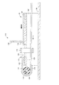
FIG. 2 shows the overall configuration of the steering system of this embodiment. The present steering system is configured with a
コラム10は、後方に位置する部分がインパネ30から車両後方に突出する状態で支持されており、その突出する後端部には、ステアリング操作部材であるステアリングホイール32が取り付けられており、コラム10はステアリングホイール32を操作可能に保持するものとなっている。ちなみに、ステアリングホイール32にはエアバッグ装置34が設けられている。コラム10のインパネ30から突出する部分は、コラムカバー36によって覆われ、また、下部は、インパネロアカバー38によってカバーされている。コラム10の前端部は、図示を省略するインタミディエイトシャフトを介し、車室外に存在する転舵装置に接続される。
The
図3に、コラム10の側面図を、図4に平面図を、図5に側面断面図を、図6に、B.A.BKT22の部分の斜視図を、それぞれ示す。図3から図5において、右側の端部が車両後方側(ステアリングホイール32側)、左側が車両前方側である。図2に示したように、コラム10は、傾斜した状態で車両に取付けられるため、実際は、図3〜図5における右側の端部は車両後方斜め上方に位置し、左側の端部は車両前方斜め下方に位置する。本実施例では、説明を簡略化するため、特に断りのない限り、それら図における右側を「車両後方側」あるいは単に「後方側」と、左側を「車両前方側」あるいは単に「前方側」と呼び、右側に向かう方向を「車両後方」あるいは単に「後方」、左側に向かう方向を「車両前方」あるいは「前方」と呼んで、説明を行う。
3 is a side view of the
コラム本体20は、シャフト部と、そのシャフト部を挿通させた状態で支持するチューブ部とを含んで構成されている。シャフト部は、車両後方側に位置させられる後部シャフト50と車両前方側に位置させられる前部シャフト52とを含んで構成されている。後部シャフト50はパイプ状に、前部シャフト52はロッド状に形成され、後部シャフト50の前方部に前部シャフト52の後方部が挿入されている。後部シャフト50の前部内周面,前部シャフト50の後部外周面には、それぞれ互いに噛合するスプラインが形成され、後部シャフト50と前部シャフト52は、軸方向に相対移動が可能かつ相対回転が不能な状態で接続されている。また、チューブ部は、車両後方側に位置させられる後部チューブ54と、車両前方側に位置させられる前部チューブ56とを含んで構成されている。後部チューブ54および前部チューブ56は、ともにパイプ状のものであり、後部チューブ54の前方部に前部チューブ56の後方部が挿入されている。後部チューブ54の前方部内面には、パイプ状をなすライナ58が設けられており、このライナ58を介することによって、前部チューブ56は後部チューブ54にがたつきなく挿入される。前部チューブ56の外周面と接触するライナ58の内周面は減摩処理が施されており、後部チューブ54と前部チューブ56との軸方向の相対移動を容易ならしめている。また、後部チューブ54の後端部および前部チューブ56の前端部には、それぞれラジアルベアリング60,62が設けられ、後部チューブ54および前部チューブ56は、それぞれ、ラジアルベアリング60,62を介して、後部シャフト50および前部シャフト52の各々を、それらの中間部において回転可能に支持している。このような構造とされていることで、コラム本体20は、伸縮可能とされているのである。
The
コラム本体20は、後部チューブ54,前部チューブ56のそれぞれにおいて、車体にの一部に取り付けられる。前部チューブ56の前方端部には、先に説明した前方ブラケット24が固定的に設けられており、この前方ブラケット24には、軸挿通穴66が設けられている。インパネR/F12に設けられた1対の取付ブラケット14の各々には、軸穴68が穿設された軸受部材70がそれぞれ固定されており、前方ブラケット24の軸挿通穴66とそれら軸受部材70の軸穴68とに、支持軸72が挿通されることで、コラム本体20は、その支持軸を中心に揺動可能に支持される(図2参照)。一方、後部チューブ54は、B.A.BKT22に保持され、そのB.A.BKT22が1対の取付ブラケット14に取り付けられることで、車体の一部に支持される。詳しく言えば、後部チューブ54には、被保持部材80が固定的に設けられており、この被保持部材80が、B.A.BKT22の構成部分であるチャンネル形状(コの字形状)をなす保持部材82によって保持されるとともに、B.A.BKT22のもう1つの構成部材である被支持プレート84が1対の取付ブラケット14に組み付けられることで、後部チューブ54が車体の一部に支持される。B.A.BKT22の取付ブラケット14に対する取付構造は、後に詳しく説明するため、ここでの説明はひとまず留保する。ちなみに、B.A.BKT22は、取り付けられた状態において、設定された離脱荷重を超える離脱方向の荷重がコラム10に作用すると、その取付状態が解除されて、車両前方方向、詳しくは、コラム10の軸線方向(離脱方向)に離脱するような構造となっている。
The
コラム10は、チルト機構90およびテレスコピック機構92を有しており、詳しくは、B.A.BKT22によるコラム本体20を保持する構造が、チルト機構90,テレスコピック機構92を構成するものとされている。B.A.BKT22の保持部材82およびコラム本体20に固定された被保持部材80は、ぞれぞれが、互いに交差する長穴94,96を有しており、それらの長穴94,96に軸部材98が挿入されている。それにより、コラム本体20は、保持部材82に設けられた長穴94の分だけ前記支持軸を中心として揺動可能とされ、また、被保持部材80に設けられた長穴96の分だけ、伸縮可能とされているのである。図3および図4には、チルト機構90およびテレスコピック機構92のロックレバー100が示されており、このロックレバー100を押し上げることにより(図3における実線の位置)、被保持部材80が保持部材82によって強く挟持され、コラム本体20の揺動位置,伸縮位置が固定されるようになっている。位置の調整は、ロックレバー100を押し下げる(図3における2点鎖線の位置)ことによって、固定を解除して行われる。なお、図2〜図5には、チルト機構90によってコラム本体20の車両後方端部が最も上方に位置させられ、テレスコピック機構92により、コラム本体20の車両後方側の部分が最も前方に位置させられた状態が示されている。
The
上述のように、設定された離脱荷重を超える離脱方向の荷重がコラム10に作用した場合、B.A.BKT22がインパネR/F12に設けられた取付ブラケット14から離脱し、それによって、コラム10の車両後方部分、詳しくは、後部シャフト50,後方チューブ54を含んで構成されるコラム本体20の後方部分およびB.A.BKT22(以下、「コラム移動部」という場合がある)が、車体の一部から、コラム10の軸線方向である離脱方向(図2の白抜矢印の方向)に離脱する。コラム10の離脱する部分は、コラム本体20の収縮を伴って、離脱方向と略同じ方向である移動方向(図2〜図5の太い矢印の方向)に移動する。なお、コラム移動部の移動範囲の終点は、前部シャフト52の上端が後部シャフト50の内径が小さくなっている内面の部分に当接することによって規定される。
As described above, when a load in the detachment direction exceeding the set detachment load acts on the
本ステアリングシステムは、取付ブラケット14から離脱したコラム移動部の移動に伴って、二次衝突の衝撃のエネルギを吸収する2つの衝撃エネルギ吸収装置を備えている。2つの衝撃エネルギ吸収装置は、いずれも、コラム移動部の移動に伴って、その移動を阻止する方向の抗力、すなわち衝撃エネルギ吸収荷重(EA荷重)を発生させる構造とされており、そのEA荷重の存在下でのコラム移動部の移動を許容することで、衝撃エネルギを吸収するものとされている。図6には、2つの衝撃エネルギ吸収装置の1つである第1EA装置110の要部の斜視が示されている。この図を補足するものとして、図7に、図6における第1EA装置110の要部が示されている部分を拡大して示す。
The present steering system includes two impact energy absorbing devices that absorb the impact energy of the secondary collision in accordance with the movement of the column moving unit that is detached from the mounting
第1EA装置は、変形部材としての、衝撃エネルギ吸収プレート(EAプレート)112と、そのEAプレート112の変形を強要する変形強要部材としての押付ローラ114とを含んで構成されている。EAプレート112は、衝撃エネルギ吸収荷重を発生させる衝撃エネルギ吸収部材として機能するものであり、B.A.BKT22の車幅方向の略中央の部位に装着されている。押付ローラ114は、肉厚管状の樹脂製のものであり、B.A.BKT22の前端部に設けられた1対の軸支持部材116によって支持されたローラ軸118によって、回転可能に支持されている。
The first EA device includes an impact energy absorbing plate (EA plate) 112 as a deforming member, and a
EAプレート112は、帯状の金属材料からなり、概ねU字状に曲げらて形成されている。EAプレート112は、湾曲部120の内側に押付ローラ114の外周面が接する状態とされ、湾曲部120に繋がる上側プレート部122は、B.A.BKT22を構成する被支持プレート84の上面に支持される状態で、車両の前後方向に延在しており、また、湾曲部120に繋がる下側プレート部124は、B.A.BKT22を構成する保持部材82の上板部の下方において、それに略平行な状態で車両の前後方向に延在している。B.A.BKT22には、角穴126が設けられ、この角穴126の両側の各々には、コの字状に屈曲して形成された1対の保持片128が、EAプレート112を挟んで互いに向かい合うように立設されており、この保持片128によって、EAプレート112が位置決めされるとともに、EAプレート112の適正な変形が担保される。
The
また、上側プレート部122の後端部は、上方に略直角に曲げ起こされるとともに概してT字状に形成された係合部130とされている。コラム10がインパネR/F12に設けられた1対の取付ブラケット14に支持された状態において、係合部130は、取付ブラケット14の各々に両端部が固定された係止バー132の凹所134と係合し、コラム移動部が離脱した際に、係止バー132によって係止されることになる(図8参照)。なお、被支持プレート84の上面には、上側プレート部122の後端部を係止する2つのストッパ136が設けられており、それらストッパ136によって、EAプレートの車両後方側への移動が禁止されている。
Further, the rear end portion of the
運転者の二次衝突によって、離脱したコラム移動部がコラム軸線方向前方(図7の太い矢印の方向)に移動する場合、EAプレート112は、係止バー132によって係合部130が係止された状態で、湾曲部120が押付ローラ114によって前方に押されることになる。それに伴って、湾曲部120の形状を概ね維持したまま、湾曲部120のEAプレート112における位置が遷り動くように変形する。この変形に要する力つまり変形抵抗がEA荷重とされ、コラム移動部がこのEA荷重の存在下で移動することにより、二次衝突の衝撃エネルギが吸収されるのである。
When the detached column moving part moves forward in the column axis direction (in the direction of the thick arrow in FIG. 7) due to the secondary collision of the driver, the
もう1つの衝撃エネルギ吸収装置である第2EA装置150は、チューブ部の伸縮部に設けられている。詳しく言えば、前部チューブ56の外周面には、後部チューブ54の前方端部より前方に、軸線方向に延びる3つの凸条152が形成されている。3つの凸条152は、周方向において3等配の位置に形成されており、それぞれが、後部チューブ54の内周面より僅かに突出する高さに形成されている。そのため、離脱したコラム移動部が移動する際、後部チューブ54の前方端部がそれら3つの凸条152を押し潰しながら、コラム本体20が収縮することになる。この3つの凸条152の変形に要する力が、EA荷重として機能し、コラム移動部は、そのEA荷重の存在下で移動し、衝撃エネルギが吸収されるのである。
The
次に、先の説明において留保しているところのB.A.BKT22の取付ブラケット14に対する取付構造について、図8〜図10をも参照しつつ説明する。図8は、コラム10が取付ブラケット14に取り付けられた状態を示す車両前方側からの斜視を、図9は、その状態における断面を、図10は、取付構造を分解した斜視を、それぞれ示している。
Next, the attachment structure of the
B.A.BKT22の被支持プレート84には、車幅方向の両端部の各々に、孔とスリットが複合したスリット孔160が設けられている。このスリット孔160は、また、1対の取付ブラケット14の各々には、下面壁を構成する下鍔部162に、取付孔164が設けられている。被支持プレート84と取付ブラケット14の下鍔部162とが、それぞれ被締結部材として機能し、それらが、スリット孔160(詳しくは、それの前端部に形成された孔部161),取付孔164を利用して、締結手段としてのボルト166およびナット168によって締結されることにより、B.A.BKT22が取付ブラケット14に取付られている。
The supported
被支持プレート84の上面と、取付ブラケット14の下鍔部162の下面との間には、樹脂によって形成された樹脂スペーサ172が介装される。樹脂スペーサ172は、上面側の四隅の各々に突起176が設けられており、また、下面側にはボルト挿通孔178の周囲から下方に延びだすような円環状のボス180が設けられている。また、被支持プレート84の下面側からフランジ付のカラー182が嵌められており、ボルト166およびナット168は、取付ブラケット14の下鍔部162,樹脂スペーサ172,被支持プレート84,フランジ付のカラー182を挟持して締結している。なお、樹脂スペーサ172のボス180の外径は、被支持プレート84のスリット孔160の孔部161の内径より僅かに小さく、内径は、フランジ付カラー182の外径より僅かに大きくされている。また、フランジ付のカラー182の先端部は下鍔部162の下面に当接し、締め代が制限されている。
A
ボルト166およびナット168によって締結された状態において、樹脂スペーサ172の各突起176は押し潰されて弾性変形させられており、被支持プレート84と取付ブラケット14の下鍔部162は、その弾性力に依拠する締結力によって締結された状態となっており、その締結力によって生じる摩擦力によって、被支持プレート84と取付ブラケット14の下鍔部162との相対移動が制限されているのである。ちなみに、被支持プレート84に設けられたスリット孔160のスリット部184は、車両前後方向に延びて車両後方側に開口しているおり、その幅は、フランジ付のカラー182の外径より大きくされ、かつ、樹脂スペーサ172のボス180の外径よりも小さくされている。そのため、車両前方方向であって、かつ、被支持プレート84の上面および取付ブラケット14の下鍔部162の下面に平行な方向(コラムの軸線方向である)に、上記摩擦力を超える荷重が、被支持プレート84に作用した場合に、被支持プレート84の取付ブラケット14に対する移動が許容されることになる。なお、その移動の際に樹脂スペーサ172のボス180の破断を伴うが、その破断に要する力は無視できるほど小さいものとされている。
In a state of being fastened by the
このような構造から、本実施例のステアリングシステムでは、上記取付構造を構成する構成要素である取付ブラケット14の下鍔部162,被支持プレート84,樹脂スペーサ172,フランジ付のカラー182,ボルト166およびナット168等を含んで、コラム10を車体の一部に固定保持するコラム支持装置200が構成されている。なお、本実施例では、上記取付構造は、2箇所において設けられており、その2箇所の取付構造により、コラム支持装置200が構成されているのである。また、そのコラム支持装置200においては、上記摩擦力に依拠して離脱荷重が決定される構造となっており、そのコラム支持装置200は、その離脱荷重を上回る荷重が作用する場合、設定された離脱方向であるコラム軸線方向へのコラム10(詳しくはコラム移動部)の離脱が許容される機構、つまり、離脱許容機構202を備えるものとされているのである。
Due to such a structure, in the steering system of the present embodiment, the
図11に、コラム10(詳しくはコラム移動部)を車両前方に引き込む装置であるコラム引込装置300とその周辺を示す。上述のように、コラム移動部はコラム支持装置200によって車体から離脱可能に支持されており、コラム引込装置300によって離脱方向の力を加えることで、コラム移動部を強制的に離脱させて車両前方に引き込むことができるのである。図12に、コラム引込装置300の断面図を示す。コラム引込装置300は、アクチュエータとしてのシリンダ装置302と、そのシリンダ装置302の排気口を開閉する開閉機構304とを含んで構成されている。また、本実施例では、シリンダ装置302は、コラム本体20の上方において、コラム10の軸線に概ね平行に配設されている。
FIG. 11 shows a
シリンダ装置302は、ハウジングとして機能するシリンダ316と、シリンダ316の内部に挿入されたピストン318と、一端部がピストン318に固定されて他端部がシリンダ316より車両後方側に突出するピストンロッド320とを含んで構成されている。シリンダ316の車両前方側の端部には軸穴が設けられた端部部材322が固着されており、シリンダ316は、その端部部材322において、前方ブラケット24を軸受部材70に支持する支持軸72によって軸支されている。また、B.A.BKT22の車両前方側の端部には、1対のブラケット324が、2つの軸支持部材116を挟む位置に付設されており、それら1対のブラケット324には、ロッド支持軸326が渡されている。ピストンロッド320の車両後方側の端部には、軸穴が設けられたロッドヘッド328が固着されており、ピストンロッド320は、そのロッドヘッド328において、ロッド支持軸326によって軸支されている。ピストン318は、シリンダ316内部の車両後方側の端部との間に比較的狭い空間を挟んで位置させられ、その空間には、固体薬剤である火薬330が充填されている。なお、図3〜図6等においては、図面が複雑にならないように、コラム引込装置300,1対のブラケット324等の図示が省略されている。
The
上記シリンダ装置302には、高圧気体を排気するための第1排気口350,第2排気口352が設けられている。また、シリンダ装置302の外周には、第1排気口350を塞ぐように、円筒状のシャッター環360が、設定されたクリアランスを保って軸方向にスライド可能に嵌合させられている。そのシャッター環360は、シリンダ装置302の外周に固定された電磁動力源たるソレノイド362の駆動軸364に連結されており、そのソレノイド362によって軸方向にスライドさせられるようにされている。ソレノイド362は、内部にコイルおよび永久磁石を有しており、所定の向きに電力が供給されると駆動軸364が延び出し、逆の向きに電力が供給されると駆動軸364が引き込まれるようにされている。図11,12には、駆動軸364が引き込まれた状態で、第1排気口350が閉ざされた状態が示されている。駆動軸364が延び出すとシャッター環360が軸方向の車両後方側(図において右側)に移動させられて、第1排気口350が開かれ、シリンダ316の内部が外部と連通した状態にされる。
The
上記シリンダ装置302は、図示を省略するスパーク電極によって火薬330に着火することによって作動する。着火によって火薬330は高圧気体を発生させ、その圧力によってピストン318が車両前方側に向かって移動する。ピストン318の移動により、B.A.BKT22は、離脱許容機構202による離脱荷重を超える力で車両前方側に向かって引張られ、コラム移動部は、車両前方に向かって取付ブラケット14から強制的に離脱させられる。
The
なお、シリンダ装置302が作動する際に、第1排気口350が開かれていた場合には、ピストン318が第1排気口350を通過した際に、第1排気口350から高圧気体が排気されてシリンダ316内部の圧力が低下するため、ピストン318に推進力が働かなくなる。すなわち、ピストン318が開かれた第1排気口350を通過することによって、コラム引込装置300による引込み動作が終了するのである。一方、図11,12に示すように、第1排気口350が閉ざされていた場合には、ピストン318が第1排気口350を通過しても高圧気体は排気されず、引き続きピストン318が移動させられる。そして、ピストン318が第2排気口352を通過した際に、第2排気口352から高圧気体が排気され、シリンダ316内部の圧力が低下するため、ピストン318に推進力が働かなくなる。すなわち、ピストン318が第2排気口352を通過することによって、コラム引込装置300による引込み動作が終了するのである。
If the
なお、第1排気口350は、ピストン318の移動距離がコラム10(詳しくはコラム移動部)が車体の一部から離脱するのに必要な移動距離である離脱距離と等しくなった際に、その第1排気口350を通過する位置に設けられている。そのため、ピストン318の移動距離が離脱距離と等しくなった際に、その第1排気口350から高圧気体が排気されて引込み動作が終了する。すなわち、第1排気口350が開かれていた場合のコラム引込量は、コラムの離脱に必要な最少距離(例えば、10mm程度)移動させる引込量(「第1引込量」の一種である)となるのである。なお、本実施例において、コラム移動部の離脱距離は、樹脂スペーサ172のコラム軸線方向の長さ寸法と概ね等しくなる。一方、第2排気口352は、ピストン318の移動距離が、離脱距離と、EA装置の吸収ストロークの半分程度の距離とを合わせた距離と等しくなった際に、その第2排気口352を通過する位置に設けられている。そのため、第1排気口350が閉ざされていた場合には、コラム移動部は、離脱距離と上記吸収ストロークの半分程度の距離とを合わせた距離(例えば、60mm程度)移動させる引込量(「第2引込量」の一種である)だけ引き込まれるのである。
The
なお、本実施例において、コラム引込装置300による引込量を変化させる引込量変更機構が、第1排気口350と開閉機構304とを含んで構成されている。さらに、開閉機構304と同様な開閉機構を第2排気口352を開閉するために設けることができ、その場合には、引込量を3段階に変化させることができる。また、その場合には、引込量変更機構が、第1排気口350,開閉機構304,第2排気口352および開閉機構とを含んで構成されることとなる。
In the present embodiment, the pull-in amount changing mechanism that changes the pull-in amount by the column pull-in
本実施例のステアリングシステムでは、コラム引込装置300は、制御装置であるステアリング電子制御ユニット(ECU)400によって作動させられる(図2参照)。そのECU400はコンピュータを主体とした装置であり、コラム引込制御プログラムを実行することによって、コラム引込装置300の制御を行う。そのECU400には、コラム引込装置300の、シリンダ装置302のスパーク電極,および開閉機構304のソレノイド362の各々が接続されており、ECU400が備える駆動回路から電力の供給を受けて作動するようにされている。また、車両には、各種のセンサが設けられており、ECU400は、それらのセンサからの信号に基づいて、コラム引込量を変更し、また、適切なタイミングでコラム移動部を引き込ませる。センサは、具体的にいえば、車両の衝突を検知する車両衝突検知器としての車両衝突センサ(C.S)402、運転者がシートベルトを着用している状態を検知するシートベルト着用検知器としてのシートベルトセンサ(S.S)404,ステアリングホイール32の変位を検出する操作部材変位検出器としての変位センサ406等のセンサが設けられている(図2参照)。
In the steering system of this embodiment, the column pull-in
変位センサ406は、回動可能に保持されたレバー408を備えており、そのレバー408が回動させられると内部のスイッチが閉じて導通を生じさせ、ECU400に検出信号を出力するものである。その変位センサ406は、コラムカバー36に、ステアリングホイール32のボス部420の前方側の端面の下部に対向するように設けられている。そして、二次衝突の際には、ステアリングホイール32の下部が運転者によって車両前方に押されてステアリングホイール32および後部シャフト50が変形するため、ボス部420の前方側の端面の下部とコラムカバー36との間隔が小さくなり、ステアリングホイール32の変位が検出される。変位センサ406は、また、レバー408がボス部420から設定された距離離間するように配設され、ステアリングホイール32が設定量変位した際にレバー408が押されて回動し、ステアリングホイール32の変位が検出されるようにされている。なお、コラムカバー36はコラム10の後部チューブ54に取り付けられており、チルト機構90,テレスコピック機構92等により、ステアリングホイール32の位置が変更されても、変位センサ406とボス部420との相対位置関係が変わらないようにされている。
The
シートベルト着用の有無は、ECU400により、シートベルトセンサ(S.S)304の検出信号に基づいて取得される。そして、シートベルト着用時には、第1排気口350を覆う位置にシャッター環360が位置させられ、第1排気口350が閉じられた状態にされる。一方、シートベルト非着用時には、シャッター環360が退避させられ、第1排気口350が開かれた状態にされる。車両が前方衝突して、車両衝突センサ(C.S)302によって車両の衝突が検知された後に、ステアリングホイール32の変位量が設定変位量になったことが変位センサ406によって検知されると、二次衝突が生じたことが検知され、シリンダ装置302が作動させられてコラム10(詳しくはコラム移動部)が引き込まれ、運転者に加わる衝撃が緩和される。
Whether or not the seat belt is worn is acquired by the
本実施例において、ステアリングホイール32の変位量は、ステアリングホイール32に加わる力、すなわち荷重の大きさと相関関係にあり、ステアリングホイール32に加わる荷重が一定の大きさを超えると、その際の変位量が設定変位量を超えることとなる。本実施例のステアリングシステムはエアバッグ装置34を備えており、運転者がエアバッグに衝突し、ステアリングホイール32にエアバッグを介して設定された荷重を超える荷重が加わると、ステアリングホイール32の変位量が設定変位量を超えて、二次衝突したことが検知される。すなわち、ステアリングホイール32の変位量が設定変位量を超えた時点が二次衝突の時点とみなされるのである。なお、本実施例において、ステアリングホイール32および後部シャフト50は二次衝突時に適度に変形するように構成されており、それらステアリングホイール32および後部シャフト50を含んで操作部材変位許容機構が構成されている。また、本実施例において、ステアリングホイール32,後部シャフト50,および変位センサ406を含んでステアリングホイール32の変位に基づいて二次衝突を検知する二次衝突検知機構が構成されている。なお、二次衝突の際には、ステアリングホイール32に加わる荷重が短時間で増大するが、本実施例において、その荷重が比較的小さい段階におけるステアリングホイール32の変位量が設定変位量とされているため、運転者に比較的大きな衝撃が加わる前の時点でコラム移動部をステアリングホイール32とともに前方に引き込むことができる。
In this embodiment, the amount of displacement of the
シートベルト非着用時には、第1排気口350が開かれて、コラム10の引込量が離脱距離と等しい引込量(第1引込量の一種である)にされる。エアバッグ衝突後に、コラム10が引き込まれて運転者とステアリングホイール32との相対速度(すなわち、衝突速度)が減少させられ、運転者がステアリングホイール32に直接的に衝突する際の衝撃が緩和される。また、コラム引込装置300による引込み動作はコラム移動部の離脱後には終了するため、運転者の慣性エネルギは十分なEA荷重によって吸収される。
When the seat belt is not worn, the
一方、シートベルト着用時には、第1排気口350が閉じられて、コラム10の引込量が離脱距離とEA装置の吸収ストロークの半分の距離とを合わせた距離と等しい引込量(第2引込量の一種である)にされる。エアバッグ衝突後に、コラム移動部が引き込まれて運転者とステアリングホイール32との衝突速度が減少させられ、衝撃が緩和されることは、シートベルト非着用時と同様である。しかし、第1排気口350が閉じられているため、コラム移動部の離脱後もコラム引込装置300による引込み動作が継続する。離脱後のコラム10は、EA装置110,150によるEA荷重に抗して移動するようにされているが、コラム引込装置300による引込みによって上記EA荷重が減少させられる。シートベルトを着用した運転者には、シートベルトの拘束力に加えて、EA荷重によるステアリングホイール32からの反力が加わるが、上述のように引込み動作が行われている間はEA荷重が減少させられているため、運転者に加わる力が過大とならず、緩やかに慣性エネルギを吸収することができる。なお、運転者の移動速度が遅い場合、例えば、シートベルト着用時で衝突速度が小さい場合等に、コラム10の引込速度が運転者の移動速度より速くなる場合があるとしても、そういった場合には、シートベルトによって運転者の慣性エネルギを十分吸収することができるため、EA荷重が小さいほど、より緩やかに運転者の慣性エネルギを吸収することができる。すなわち、その場合には、コラム10の引込によってEA荷重を0にすることにより、衝撃をより効果的に緩和しているのである。
On the other hand, when the seat belt is worn, the
以上のように、シートベルト着用の有無に応じてコラム10の引込量を変えることによって、衝撃を緩和する装置(シートベルト,EA装置等)から運転者に加えられる力の大きさを全体として適度な大きさにすることができ、運転者の衝撃をより効果的に緩和することができるのである。
As described above, the amount of force applied to the driver from the device (seat belt, EA device, etc.) that reduces the impact by changing the pull-in amount of the
<第2実施例>
上記実施例において、コラムカバー36に設けられた変位センサ406によって二次衝突を検出していたが、変位センサ406を上記とは異なる場所に設けることができる。本実施例のステアリングシステムは、第1実施例のシステムと略同様の構成であるため、異なる構成を中心に説明し、同様の構成についての説明は省略する。また、本実施例の説明において、第1実施例のシステムと同じ機能の構成要素については、同じ符号を用いて対応するものであることを示し、それらの説明は省略するあるいは簡略に行うものとする。
<Second embodiment>
In the above embodiment, the secondary collision is detected by the
ステアリングコラム500(以後、「コラム」と略記する場合がある)の後方部分を拡大した側面断面図を図13に示す。本実施例において、後部シャフト510は、後部チューブ512に、前方に移動可能に保持されている。すなわち、後部シャフト510の軸受60の前方側は軸受60の内径よりも径が大きくされており、後方への移動が禁止されている。それに対して、後部シャフト510の軸受60の後方側の部分は、軸受60と比較的緩やかに嵌合できるようにされているため、前方への移動が許容されるのである。後部シャフト510には、軸受60と軸方向に離間した部分に止め輪520が取り付けられている。その止め輪520と軸受60との間には、弾性部材たる圧縮コイルスプリング522(以後、「スプリング」と略記する場合がある)が設けられている。そのスプリング522は、設定量圧縮された状態で軸受60と止め輪520とに挟まれており、後部シャフト510を後方に付勢している。その付勢力は、走行時等にステアリングホイール32が操作されても、後部シャフト510は殆ど軸方向に動くことがない大きさとされている。
FIG. 13 is an enlarged side cross-sectional view of a rear portion of the steering column 500 (hereinafter sometimes abbreviated as “column”). In this embodiment, the
後部チューブ512の外周面には、変位センサ530が固定されている。その変位センサ530は、上記実施例の変位センサ406と同様の構成であり、回動可能に保持されたアーム532を備え、そのアーム532が回動させられると内部のスイッチが閉じて導通を生じさせ、ECU400に検出信号を出力するものである。また、変位センサ530は、ECU400に接続されている。後部チューブ512には、貫通穴536が設けられており、その貫通穴536を通って変位センサ530のアーム532が後部チューブ512の内側に延び出している。後部シャフト510の外周には、カラー540が嵌合させられ、固着されている。
A
二次衝突時に、後部シャフト510がスプリング522の付勢力に抗して前方に押されると、カラー540がアーム532を回動させ、変位センサ530内のスイッチがONにされる。そして、ECU400により、二次衝突の発生が検知され、コラム引込装置300が作動させられて、コラム500(詳しくは、コラム移動部)が、車両前方に引き込まれるのである。すなわち、本実施例において、後部シャフト510に加わる荷重が設定された荷重を超える時点が、二次衝突の時点とみなされるのである。本実施例のステアリングシステムでは、スプリング522の弾性係数,プリロード(通常時に、軸受60と止め輪520とに挟まれた状態でスプリング522が発生する弾性力)等を変更することにより、二次衝突が検知される際の後部シャフト510に加わる荷重を変更することができる。
When the
なお、本実施例において、止め輪520,軸受60,スプリング522を含んで操作部材変位許容機構が構成されている。その操作部材変位許容機構は、ステアリングホイール32に加わる軸方向の荷重に応じて、後部シャフト510が軸方向前方へ変位することを許容するものである。また、変位センサ530およびカラー540を含んで、二次衝突検知機構が構成されている。上述以外の作動,作用・効果については、上記実施例と同様である。
In this embodiment, the operating member displacement allowance mechanism is configured including the retaining
<第3実施例>
上記実施例において、コラム引込装置300がB.A.BKT22と前方ブラケット24との間に設けられていたが、態様の異なるコラム引込装置をB.A.BKT22の後方に設けることもできる。図14に、第3実施例のステアリングシステムにおけるステアリングコラムの取付ブラケットへの取付状態を示す。図14は、ステアリングコラムを車両左側から見た側面図であり、シリンダ装置が断面図とされている。本実施例のステアリングシステムは、第1実施例のシステムと略同様の構成であるため、異なる構成を中心に説明し、同様の構成についての説明は省略する。また、本実施例の説明において、第1実施例のシステムと同じ機能の構成要素については、同じ符号を用いて対応するものであることを示し、それらの説明は省略するあるいは簡略に行うものとする。
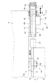
<Third embodiment>
In the above embodiment, the column pull-in
本実施例において、コラム引込装置600は、1対の取付ブラケット14に渡された支持バー604の下面に固定されて支持されている。コラム引込装置600は、第1実施例と同様に、シリンダ装置608および開閉機構610を備えている。そのシリンダ装置608は、ハウジングとして機能するシリンダ616と、シリンダ616の内部に挿入されたピストン618と、一端部がピストン618に固定されて他端部がシリンダ616より車両前方側に突出するピストンロッド620と、ピストンロッド620の他端部に固定的に取り付けられたプランジャヘッド622とを含んで構成されている。ピストン618は、シリンダ616内部の車両後方側の端部との間に比較的狭い空間を挟んで位置させられ、その空間には、固体薬剤である火薬624が充填されている。プランジャヘッド622の車両前方側の端部である先端部は、B.A.BKT22の保持部材82および被支持プレート84の車幅方向の中央であって車両後方側の端部に当接させられている。
In this embodiment, the column pull-in
上記シリンダ装置608には、第1実施例のシリンダ装置302と同様に、高圧気体を排気するための第1排気口350,第2排気口352が設けられている。開閉機構610については、第1実施例の開閉機構304と同様であるため、同じ符号を付して説明を省略する。また、第1排気口350および第2排気口352の説明についても、第1実施例の開閉機構304と同様である。なお、シリンダ装置608および開閉機構610の各々は、第1実施例と同様に、ECU400に接続されている。
Similar to the
上記シリンダ装置608は、図示を省略するスパーク電極によって火薬624に着火することによって作動する。着火によって火薬624は高圧気体を発生させ、その圧力によってピストン618が車両前方側に向かって移動する。ピストン618の移動により、プランジャヘッド622は、離脱許容機構202による離脱荷重を超える力でB.A.BKT22を押し、B.A.BKT22、つまり、コラム移動部を車両前方に向かって取付ブラケット14から強制的に離脱させる。
The
本実施例において、第1実施例と同様に、シートベルト着用の有無に基づいて第1排気口350を開閉し、コラム10(詳しくは、コラム移動部)の引込量を変化させ、運転者の衝撃をより効果的に緩和する。コラム引込装置600の構成以外、例えば、構成、作動、作用・効果については、第1実施例と同様であるため説明を省略する。なお、本コラム引込装置600は、第2実施例にも適用可能である。
In the present embodiment, as in the first embodiment, the
<変形例>
上記各実施例において、第1排気口350は、1つだけ設けられていたが、例えば、周に沿って等角度間隔に複数の排気口を設けてもよい。そうすることによって、単位時間当たりの排気量(排気速度)を増加させることや、排気口の面積を小さくすることができる。
<Modification>
In each of the above embodiments, only one
上記各実施例において、引込量を2段階に分けていたが、3段階以上にすることもできる。また、シートベルト着用の有無だけではなく、衝突速度,運転者の体重等に基づいて引込量を決定することもできる。 In each of the above-described embodiments, the pull-in amount is divided into two stages, but can be made into three or more stages. Further, the pull-in amount can be determined based not only on whether or not the seat belt is worn, but also based on the collision speed, the weight of the driver, and the like.
10:ステアリングコラム 12:インパネリインフォースメント 14:コラム取付ブラケット(車体の一部) 20:コラム本体 22:ブレイクアウェイブラケット 32:ステアリングホイール(ステアリング操作部材) 34:エアバッグ装置 84:被支持プレート(被締結部材)90:チルト機構 92:テレスコピック機構 110:第1EA装置(衝撃エネルギ吸収装置) 112:衝撃エネルギ吸収プレート(変形部材) 150:第2EA装置(衝撃エネルギ吸収装置) 172:樹脂スペーサ 200:コラム支持装置 202:離脱許容機構 300:コラム引込装置 302:シリンダ装置(アクチュエータ) 304:開閉機構 350:第1排気口 360:シャッター環 362:ソレノイド(電磁動力源) 400:ステアリング電子制御ユニット(制御装置) 404:シートベルトセンサ[S.S](シートベルト着用検知器) 406:変位センサ(操作部材変位検出器) 500:ステアリングコラム 520:止め輪 522:圧縮コイルスプリング 530:変位センサ(操作部材変位検出器) 600:コラム引込装置 608:シリンダ装置(アクチュエータ) 610:開閉機構
10: Steering column 12: Instrument panel reinforcement 14: Column mounting bracket (part of the vehicle body) 20: Column body 22: Breakaway bracket 32: Steering wheel (steering operation member) 34: Airbag device 84: Supported plate (covered) Fastening member) 90: tilt mechanism 92: telescopic mechanism 110: first EA device (impact energy absorbing device) 112: impact energy absorbing plate (deformable member) 150: second EA device (impact energy absorbing device) 172: resin spacer 200: column Support device 202: Release allowing mechanism 300: Column retracting device 302: Cylinder device (actuator) 304: Opening / closing mechanism 350: First exhaust port 360: Shutter ring 362: Solenoid (electromagnetic power source) 400: Steering power The control unit (control device) 404: seat belt sensor [S. S] (Seat belt wearing detector) 406: Displacement sensor (operation member displacement detector) 500: Steering column 520: Retaining ring 522: Compression coil spring 530: Displacement sensor (operation member displacement detector) 600: Column retracting device 608 : Cylinder device (actuator) 610: Opening / closing mechanism
Claims (4)
前記ステアリング操作部材に加わる衝撃に対する前記ステアリングコラムの車体の一部からの離脱を許容する離脱許容機構を備えて、そのステアリングコラムを車体の一部に固定支持させるコラム支持装置と、
前記ステアリングコラムを車両前方に引き込む量である引込量を変化させて前記ステアリングコラムを引き込むコラム引込装置と
を含んで構成された車両用ステアリングシステムであって、
前記コラム引込装置が、
シリンダと、そのシリンダの内部に充満させられる高圧気体の圧力によってそのシリンダと相対移動させられるピストンとを備えて、前記ステアリングコラムを引き込むための動力源となるアクチュエータと、
前記ステアリングコラムの引込量を変化させるために、前記シリンダに設けられて前記ピストンの移動途中に前記高圧気体を外部へ排気する排気口を開閉させる開閉機構と
を備えたことを特徴とする車両用ステアリングシステム。 A steering column for operably holding a steering operation member at one end;
A column support device that includes a disengagement allowance mechanism that allows disengagement of the steering column from a part of the vehicle body with respect to an impact applied to the steering operation member;
A vehicle steering system including a column pull-in device that pulls in the steering column by changing a pull-in amount that is a pull-in amount of the steering column forward of the vehicle;
The column pull-in device is
An actuator serving as a power source for retracting the steering column, comprising a cylinder and a piston that is moved relative to the cylinder by the pressure of the high-pressure gas filled in the cylinder;
An opening / closing mechanism provided in the cylinder for opening and closing an exhaust port for exhausting the high-pressure gas to the outside during the movement of the piston in order to change the pull-in amount of the steering column;
Steering system for a vehicle, characterized in that it comprises a.
Priority Applications (1)
| Application Number | Priority Date | Filing Date | Title |
|---|---|---|---|
| JP2004246418A JP4371008B2 (en) | 2004-08-26 | 2004-08-26 | Vehicle steering system |
Applications Claiming Priority (1)
| Application Number | Priority Date | Filing Date | Title |
|---|---|---|---|
| JP2004246418A JP4371008B2 (en) | 2004-08-26 | 2004-08-26 | Vehicle steering system |
Publications (2)
| Publication Number | Publication Date |
|---|---|
| JP2006062492A JP2006062492A (en) | 2006-03-09 |
| JP4371008B2 true JP4371008B2 (en) | 2009-11-25 |
Family
ID=36109347
Family Applications (1)
| Application Number | Title | Priority Date | Filing Date |
|---|---|---|---|
| JP2004246418A Expired - Fee Related JP4371008B2 (en) | 2004-08-26 | 2004-08-26 | Vehicle steering system |
Country Status (1)
| Country | Link |
|---|---|
| JP (1) | JP4371008B2 (en) |
Families Citing this family (5)
| Publication number | Priority date | Publication date | Assignee | Title |
|---|---|---|---|---|
| KR100836909B1 (en) * | 2006-07-12 | 2008-06-11 | 현대자동차주식회사 | Impact absorbing system of steering column for vehicle |
| JP4831359B2 (en) * | 2007-06-15 | 2011-12-07 | 三菱自動車工業株式会社 | Shock absorption structure of steering column device |
| JP5751174B2 (en) * | 2012-01-13 | 2015-07-22 | トヨタ自動車株式会社 | Instrument panel structure |
| CN112061224B (en) * | 2020-08-14 | 2022-08-30 | 开沃新能源汽车集团股份有限公司 | Automatic drive-by-wire telescopic mechanical redundant steering column |
| WO2023119634A1 (en) * | 2021-12-24 | 2023-06-29 | 株式会社ジェイテクト | Steering device |
-
2004
- 2004-08-26 JP JP2004246418A patent/JP4371008B2/en not_active Expired - Fee Related
Also Published As
| Publication number | Publication date |
|---|---|
| JP2006062492A (en) | 2006-03-09 |
Similar Documents
| Publication | Publication Date | Title |
|---|---|---|
| JP3876291B2 (en) | Safety device for lifting the hood of a car in the event of a collision | |
| US7080855B2 (en) | Safety steering column, motor vehicle with a safety system and safety method | |
| US20070267892A1 (en) | Device and method for raising the hood of a motor vehicle during a collision with a pedestrain | |
| JP4371008B2 (en) | Vehicle steering system | |
| JP2002514549A (en) | Safety steering column, vehicle safety system and vehicle with safety system and safety method | |
| KR102659231B1 (en) | Device of steering column for working together airbag system | |
| JP4151655B2 (en) | Vehicle steering system | |
| JP2012506809A (en) | Trigger type stroke actuator for safety system | |
| JP2007055580A (en) | Steering column | |
| JP2006193079A (en) | Steering system for vehicle | |
| JP4479483B2 (en) | Vehicle steering system | |
| JP4244949B2 (en) | Vehicle steering system | |
| JP4151660B2 (en) | Vehicle steering system | |
| JP4239994B2 (en) | Vehicle steering system | |
| JP2014091406A (en) | Vehicular pop-up hood device | |
| JP2006111094A (en) | Steering system for vehicle | |
| JP4487722B2 (en) | Vehicle steering system | |
| JP2006111096A (en) | Steering system for vehicle | |
| JP2007055582A (en) | Steering column | |
| JP2006111093A (en) | Steering system for vehicle | |
| JP2006111097A (en) | Steering system for vehicle | |
| JP5163009B2 (en) | Vehicle occupant protection device | |
| JP2007125956A (en) | Steering device for vehicle | |
| JP6127963B2 (en) | Actuator | |
| JP2007055581A (en) | Steering column |
Legal Events
| Date | Code | Title | Description |
|---|---|---|---|
| A621 | Written request for application examination |
Free format text: JAPANESE INTERMEDIATE CODE: A621 Effective date: 20060915 |
|
| A977 | Report on retrieval |
Free format text: JAPANESE INTERMEDIATE CODE: A971007 Effective date: 20081226 |
|
| A131 | Notification of reasons for refusal |
Free format text: JAPANESE INTERMEDIATE CODE: A131 Effective date: 20090120 |
|
| A521 | Written amendment |
Free format text: JAPANESE INTERMEDIATE CODE: A523 Effective date: 20090316 |
|
| TRDD | Decision of grant or rejection written | ||
| A01 | Written decision to grant a patent or to grant a registration (utility model) |
Free format text: JAPANESE INTERMEDIATE CODE: A01 Effective date: 20090811 |
|
| A01 | Written decision to grant a patent or to grant a registration (utility model) |
Free format text: JAPANESE INTERMEDIATE CODE: A01 |
|
| A61 | First payment of annual fees (during grant procedure) |
Free format text: JAPANESE INTERMEDIATE CODE: A61 Effective date: 20090824 |
|
| FPAY | Renewal fee payment (event date is renewal date of database) |
Free format text: PAYMENT UNTIL: 20120911 Year of fee payment: 3 |
|
| FPAY | Renewal fee payment (event date is renewal date of database) |
Free format text: PAYMENT UNTIL: 20120911 Year of fee payment: 3 |
|
| FPAY | Renewal fee payment (event date is renewal date of database) |
Free format text: PAYMENT UNTIL: 20120911 Year of fee payment: 3 |
|
| FPAY | Renewal fee payment (event date is renewal date of database) |
Free format text: PAYMENT UNTIL: 20130911 Year of fee payment: 4 |
|
| LAPS | Cancellation because of no payment of annual fees |