JP2012502204A - Floor construction equipment - Google Patents
Floor construction equipment Download PDFInfo
- Publication number
- JP2012502204A JP2012502204A JP2011525996A JP2011525996A JP2012502204A JP 2012502204 A JP2012502204 A JP 2012502204A JP 2011525996 A JP2011525996 A JP 2011525996A JP 2011525996 A JP2011525996 A JP 2011525996A JP 2012502204 A JP2012502204 A JP 2012502204A
- Authority
- JP
- Japan
- Prior art keywords
- plate
- rail
- floor construction
- construction apparatus
- plates
- Prior art date
- Legal status (The legal status is an assumption and is not a legal conclusion. Google has not performed a legal analysis and makes no representation as to the accuracy of the status listed.)
- Pending
Links
Images


Classifications
-
- E—FIXED CONSTRUCTIONS
- E04—BUILDING
- E04F—FINISHING WORK ON BUILDINGS, e.g. STAIRS, FLOORS
- E04F21/00—Implements for finishing work on buildings
- E04F21/20—Implements for finishing work on buildings for laying flooring
- E04F21/24—Implements for finishing work on buildings for laying flooring of masses made in situ, e.g. smoothing tools
- E04F21/241—Elongated smoothing blades or plates, e.g. screed apparatus
- E04F21/244—Elongated smoothing blades or plates, e.g. screed apparatus with means to adjust the working angle of the leveling blade or plate
Landscapes
- Engineering & Computer Science (AREA)
- Architecture (AREA)
- Civil Engineering (AREA)
- Structural Engineering (AREA)
- Floor Finish (AREA)
- Conveying And Assembling Of Building Elements In Situ (AREA)
Abstract
本発明に係る床施工装置は、施工面に配置されるガイドユニットと、ガイドユニットに案内されて移動しながら施工面を平坦化する平坦化ユニットと、を含んで構成されるので、施工面を平坦化するための施工時間及び費用を低減することができる。 The floor construction apparatus according to the present invention includes a guide unit arranged on the construction surface and a flattening unit that flattens the construction surface while being guided and moved by the guide unit. The construction time and cost for flattening can be reduced.
Description
本発明は、施工面を仕上げ処理するために施工面を平坦化する床施工装置に関するものである。 The present invention relates to a floor construction apparatus for flattening a construction surface in order to finish the construction surface.
一般に、室内の床や歩道、道路のような室外の床面は実用性及び審美性の要求水準に応じて多様な材料、例えば、タイル、歩道ブロックまたは仕上げ材などで仕上げ処理され、それらタイル、歩道ブロックまたは仕上げ材の種類によって適切な施工方法が採用されている。 In general, outdoor floors such as indoor floors, sidewalks, and roads are finished with various materials, such as tiles, sidewalk blocks, or finishing materials, depending on the level of utility and aesthetic requirements. An appropriate construction method is adopted depending on the type of block or finishing material.
このように施工面をタイル、歩道ブロックまたは仕上げ材等で仕上げ処理するためには施工面の平坦化が先行される。 Thus, in order to finish the construction surface with tiles, sidewalk blocks, or finishing materials, the construction surface is first flattened.
従来の場合は施工面を平坦化するために作業者が手作業で所定の工具を利用して施工面全体を直接平らにする方式で行われていた。 In the conventional case, in order to flatten the construction surface, an operator manually performs a method of directly flattening the entire construction surface using a predetermined tool.
そのため、従来は施工面の平坦化作業を速やかに遂行することができず長時間が掛かるという不都合な点があった。また、大面積の施工面を平坦化するためには多数の作業者が必要とされるので人件費が大幅に上昇するなど、施工面の平坦化過程に必要な費用が上昇するという不都合な点があった。 Therefore, conventionally, there has been an inconvenience that the flattening operation of the construction surface cannot be performed quickly and it takes a long time. In addition, in order to flatten a construction surface with a large area, a large number of workers are required, resulting in a significant increase in labor costs, such as a significant increase in labor costs. was there.
本発明は、前記した従来技術の問題点を解決するためのもので、本発明の目的は、施工面に配置されるガイドユニットと、ガイドユニットに案内されて移動しながら施工面を平坦化する平坦化ユニットと、を含んで構成されることで、施工面を平坦化するための施工時間及び費用を低減することが可能で、欠陥補修による諸費用を画期的に節減し得る床施工装置を提供しようとする。 The present invention is for solving the problems of the prior art described above, and an object of the present invention is to flatten the construction surface while being guided and moved by the guide unit arranged on the construction surface. By including a flattening unit, it is possible to reduce the construction time and cost for flattening the construction surface, and it is possible to dramatically reduce various expenses due to defect repair. Try to provide.
また、本発明は施工面の形状に合せて平坦化ユニットの下面の形状を調節し得る床施工装置を提供しようとする。 Moreover, this invention tends to provide the floor construction apparatus which can adjust the shape of the lower surface of a planarization unit according to the shape of a construction surface.
前記目的を達成するため本発明に係る床施工装置は、施工面の平坦化のためにその下側エッジが前記施工面に塗布された物質に接触するプレートを含む平坦化ユニットと、前記施工面上での前記平坦化ユニットの移動を案内するガイドユニットと、を包含して構成される。 In order to achieve the above object, a floor construction apparatus according to the present invention includes a flattening unit including a plate whose lower edge is in contact with a material applied to the construction surface for planarizing the construction surface, and the construction surface. And a guide unit for guiding the movement of the flattening unit above.
ここで、前記平坦化ユニットは、前記施工面の平坦化過程中、前記施工面に塗布された物質の残余分が前記プレートの一方側へ移動することを防止するように、前記プレートの一面に付着され前記プレートの一面から延長される案内プレートを更に包含して構成される。 Here, the flattening unit is disposed on one surface of the plate so as to prevent a residue of the substance applied to the work surface from moving to one side of the plate during the flattening process of the work surface. A guide plate attached and extended from one side of the plate is further included.
一方、施工面にリッジなどを形成するために前記プレートの下側エッジには前記施工面に対して開放されるノッチが形成され、前記平坦化ユニットは、前記プレートにスライド可能に設置されて前記プレートのノッチの開放された形状を調節するサブプレートを更に包含して構成される。 On the other hand, in order to form a ridge or the like on the construction surface, a notch that is open to the construction surface is formed on the lower edge of the plate, and the flattening unit is slidably installed on the plate and It further includes a sub-plate for adjusting the open shape of the notch of the plate.
前記プレートが長さ方向に延長または収縮できるように、前記プレートは、第1プレートと、前記第1プレートに長さ方向へ移動可能に連結される第2プレートと、を含んで構成される。 The plate includes a first plate and a second plate connected to the first plate so as to be movable in the length direction so that the plate can be extended or contracted in the length direction.
一方、前記ガイドユニットは一つ以上のレールにより構成され、前記平坦化ユニットには、前記レール上に移動可能に配置されて前記平坦化ユニットと連結されるフレームが具備される。 Meanwhile, the guide unit includes one or more rails, and the flattening unit includes a frame that is movably disposed on the rails and connected to the flattening unit.
ここで、前記レールには、前記レールを前記施工面に固定させると共に前記レールの前記施工面からの高さを調節し得る固定装置が具備される。 Here, the rail is provided with a fixing device that can fix the rail to the construction surface and adjust the height of the rail from the construction surface.
また、前記レールの下側には車輪が設置され、前記レールと前記車輪間には上汽車輪の高さを調節する乗降装置が具備され、前記レールと前記車輪間には前記車輪を上側方向及び下側方向に回転させる回転装置が具備される。 Further, a wheel is installed on the lower side of the rail, and a boarding / alighting device that adjusts the height of the upper wheel is provided between the rail and the wheel, and the wheel is disposed in an upward direction between the rail and the wheel. A rotating device for rotating in the downward direction is provided.
一方、前記レールには前記フレームの移動位置を測定できるように目盛りが形成されることが好ましい。 Meanwhile, it is preferable that a scale is formed on the rail so that the moving position of the frame can be measured.
そして、前記平坦化ユニットには、前記平坦化ユニットの前記レールに対する高低を調節する高さ調節装置が具備されることが好ましい。 The flattening unit preferably includes a height adjusting device that adjusts the height of the flattening unit relative to the rail.
また、前記レールは、前記施工面に設置される少なくとも一つの第1レールと、前記第1レール上にスライド可能に配置され、前記平坦化ユニットが載置される少なくとも一つの第2レールと、を包含して構成される。 In addition, the rail is at least one first rail installed on the construction surface, slidably disposed on the first rail, and at least one second rail on which the flattening unit is placed, It is configured to include.
一方、前記ガイドユニットは一つのレールにより構成され、前記平坦化ユニットは前記フレームを通して前記一つのレールと連結されて、前記平坦化ユニットの前記レールと連結される側の反対側には取っ手が具備される。 Meanwhile, the guide unit is constituted by one rail, the flattening unit is connected to the one rail through the frame, and a handle is provided on the opposite side of the flattening unit to the side connected to the rail. Is done.
また、前記ガイドユニットは一つのレールにより構成され、前記平坦化ユニットは前記フレームを通して前記一つのレールと連結されて、前記平坦化ユニットの前記レールと連結される側の反対側には車輪が具備される。 The guide unit includes a single rail, the flattening unit is connected to the single rail through the frame, and a wheel is provided on the opposite side of the flattening unit to the side connected to the rail. Is done.
前記レールは少なくとも一部分が折畳みできるように構成される。 The rail is configured to be at least partially foldable.
本発明に係る床施工装置は、前記ガイドユニットの少なくとも一つが装着されて前記ガイドユニットを移動させる移動ユニットを更に包含し、作業物が配置される作業が具備され、作業者が位置するサドルを具備し、前記施工面に水を供給する給水装置を具備することができる。 The floor construction apparatus according to the present invention further includes a moving unit that is mounted with at least one of the guide units and moves the guide unit, and includes a work in which a work is arranged, and a saddle on which an operator is positioned. And a water supply device for supplying water to the construction surface.
一方、前記プレートは一列配置される複数のプレートにより構成され、前記平坦化ユニットは、前記複数のプレートが配置される方向に延長されて、前記複数のプレートを支持して前記複数のプレートの配置形状を維持する支持部材と、前記支持部材の位置を固定させる固定部材と、を含んで構成される。 On the other hand, the plate is constituted by a plurality of plates arranged in a row, and the flattening unit is extended in a direction in which the plurality of plates are arranged to support the plurality of plates and to arrange the plurality of plates. A support member that maintains the shape and a fixing member that fixes the position of the support member.
ここで、前記複数のプレートが相互連結される部位には凹溝部及び突出部が形成される。 Here, a recessed groove portion and a protruding portion are formed at a portion where the plurality of plates are interconnected.
また、前記複数のプレートには、前記複数のプレートの長さ方向に延長される溝が形成され、前記支持部材には前記複数のプレートの溝に挿入される突起が形成される。 Further, the plurality of plates are formed with grooves extending in the length direction of the plurality of plates, and the support member is formed with a protrusion inserted into the grooves of the plurality of plates.
一方、前記プレートの下端部は前記プレートの一面から水平方向に延長され、前記複数のプレートには上下方向に目盛りが形成される。 Meanwhile, a lower end portion of the plate extends in a horizontal direction from one surface of the plate, and scales are formed in the vertical direction on the plurality of plates.
そして、前記複数のプレートの一方側には前記複数のプレートが連結された形態の高さよりも高い基準プレートが具備され、前記基準プレートの前記複数のプレートに対向する面には目盛りが形成される。 A reference plate having a height higher than that of the plurality of plates connected to each other is provided on one side of the plurality of plates, and a scale is formed on a surface of the reference plate facing the plurality of plates. .
本発明に係る床施工装置は、施工面に配置されるガイドユニットと、ガイドユニットに案内されて移動しながら施工面を平坦化する平坦化ユニットと、を含んで構成されるので、施工面を平坦化するための施工時間及び費用を低減し得るという効果がある。 The floor construction apparatus according to the present invention includes a guide unit arranged on the construction surface and a flattening unit that flattens the construction surface while being guided and moved by the guide unit. There is an effect that construction time and cost for flattening can be reduced.
また、本発明に係る床施工装置は、平坦化ユニットのプレートに対して上下方向または左右方向への位置調節ができるように設置されるサブプレートを具備して、サブプレートの上下方向または左右方向の位置を調節しながらプレートのノッチの開放形状を調節することができるので、施工作業の種類によって施工面に形成されるパターン、例えば、リッジ形状などを多様に調節することができるという効果がある。 Moreover, the floor construction apparatus according to the present invention includes a subplate that is installed so that the position of the flattening unit can be adjusted in the vertical direction or the horizontal direction with respect to the plate of the flattening unit. Since the opening shape of the notch of the plate can be adjusted while adjusting the position of the plate, there is an effect that the pattern formed on the construction surface, for example, the ridge shape can be variously adjusted according to the kind of construction work. .
更に、本発明に係る床施工装置は、プレートの施工面に対する高さを調節する高さ調節装置を具備するので、プレートと施工面間の間隔及び水平度を容易に調節して、作業の種類によって施工面に対するプレートの角度を調節することができるという効果がある。
また、本発明に係る床施工装置は、平坦化ユニットの移動を案内するガイドユニットが施工面に配置される複数の第1レールと、平坦化ユニットが移動可能に載置される第2レールと、により構成されるので、平坦化する施工面の面積に対応してレールの幅を自由に調節することができるという効果がある。
Furthermore, since the floor construction apparatus according to the present invention includes a height adjustment device that adjusts the height of the plate with respect to the construction surface, the distance between the plate and the construction surface and the levelness can be easily adjusted, and the type of work. The effect is that the angle of the plate with respect to the construction surface can be adjusted.
Moreover, the floor construction apparatus according to the present invention includes a plurality of first rails on which a guide unit for guiding the movement of the flattening unit is disposed on the construction surface, and a second rail on which the flattening unit is movably mounted. Therefore, there is an effect that the width of the rail can be freely adjusted in accordance with the area of the construction surface to be flattened.
また、本発明に係る床施工装置は、プレートが複数の部材が相互長さ方向に相対変位できるように設置された構造で構成されるので、プレートの長さを容易に調節することができる。従って、施工面の施工面積によってレールの幅が変化する場合、多様な長さを有する複数のプレートを備えてレール間の幅に対応して複数のプレートを交替するといった短所を除去することができる。 Moreover, since the floor construction apparatus which concerns on this invention is comprised by the structure in which the plate was installed so that a some member could be relatively displaced in a mutual length direction, the length of a plate can be adjusted easily. Therefore, when the width of the rail varies depending on the construction area of the construction surface, it is possible to eliminate the disadvantage of providing a plurality of plates having various lengths and replacing the plurality of plates according to the width between the rails. .
また、本発明に係る床施工装置は、施工面に設置されるタイル、仕上げ材または工具などの作業物が配置される作業台と作業者が位置されるサドルが具備されるので作業者の作業効率をより向上し得るという効果がある。 Further, the floor construction apparatus according to the present invention includes a work table on which work items such as tiles, finishing materials or tools installed on the construction surface are arranged and a saddle on which the worker is located, so that the work of the worker is performed. There is an effect that the efficiency can be further improved.
また、本発明に係る床施工装置は、平坦化ユニットの複数のプレートが個別的に上下方向へ位置調節することが可能で、それに従って、施工面の高低に合せて複数のプレートの上下方向への位置を調節することで平坦化ユニットの下面の形状を施工面に合せて調節することができるので、正確な量の物質を施工面に塗布して施工面の品質を向上し得るという効果がある。 Moreover, the floor construction apparatus which concerns on this invention can adjust the position of the several plate of a planarization unit individually to an up-down direction, and according to it, according to the height of a construction surface, to the up-down direction of several plates. By adjusting the position, the shape of the lower surface of the flattening unit can be adjusted according to the construction surface, so the effect of improving the quality of the construction surface by applying an accurate amount of substance to the construction surface. is there.
添付された図面を参照して本発明に係る床施工装置の好ましい実施例に関して説明すると次の通りである。 A preferred embodiment of the floor construction apparatus according to the present invention will be described with reference to the accompanying drawings.
<第1実施例>
以下、図1乃至図8を参照して、本発明の第1実施例に係る床施工装置に対して説明する。
<First embodiment>
Hereinafter, the floor construction apparatus according to the first embodiment of the present invention will be described with reference to FIGS.
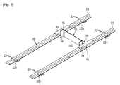
図1乃至図4に示したように、本発明の第1実施例に係る床施工装置は、施工面に塗布された物質を平坦化するために長さ方向に延長されてその下側エッジが施工面に塗布された物質に接触されるプレート100を含む平坦化ユニット10と、施工面上における前記平坦化ユニット10の移動を案内するガイドユニット20と、を含んで構成される。
As shown in FIGS. 1 to 4, the floor construction apparatus according to the first embodiment of the present invention is extended in the length direction in order to flatten the material applied to the construction surface, and the lower edge is extended. The flattening
前記プレート100は、平板状に形成され、その中心が彎曲された形に形成されるなど多様な形状に形成される。また、プレート100の下側エッジはプレート100の長さ方向に直線形状に形成される。
The
前記ガイドユニット20は、レール21と、レール21を施工面に固定させる固定装置22と、を含んで構成される。ここで、固定装置22は、レール21の両方端部または中間部に配置され、施工面からのレール21の高さを調節し得る構造を適用することが好ましい。例えば、固定装置22は、図1に示したように、レール21に固定されて雌ねじ山が形成される少なくとも一つの貫通孔を有するブラケット221と、ブラケット221の貫通孔に挿入され垂直方向に延長されて外周に貫通孔の雌ねじ山と歯合される雄ねじ山が形成されて下端が施工面に支持されるロード222と、ロード222の上端に結合されるハンドル103と、を含んで構成される。このような構成によって作業者がハンドル103を廻してロード222を回転させると、ブラケット221と施工面間の間隔が調節されながらレール21の高さが調節される。従って、レール21の各部分に設置された固定装置22を利用してレール21を施工面に固定させると共にレール21の水平調節を含む施工面に対する勾配を調節することができる。一方、ガイドユニット20の固定装置22は前記構成に限定されず、レール21の高さを調節し得る多様な構成を適用することができる。また、固定装置22はレール21の長さ方向に沿って複数配置することができる。
The
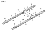
一方、図2及び図3に示したように、レール21を施工面に支持させると同時にレール21の移動が容易にできるように、レール21の下側には回転可能に設置される車輪231を含む固定機構23が具備される。このような構成によって、作業者がレール21を容易に運搬して作業能率を向上させる効果がある。図3に示したように、このような車輪231は、レール21の下側面に沿って所定間隔に配置される。車輪231は少なくとも一つ以上のベアリングで構成される。
On the other hand, as shown in FIGS. 2 and 3, a
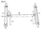
図4及び図5に示したように、平坦化ユニット10とガイドユニット20とを連結するために、レール21上に移動可能に配置されて平坦化ユニット10の両側に連結される一対のフレーム15を含んで構成することができる。ここで、図3に示したように、レール21にはフレーム15の移動位置を測定できるように目盛り217が形成されることが好ましい。図5に示したように、フレーム15の下側、即ち、フレーム15とレール21の間には、フレーム15が移動するときレール21との摩擦を低減するように、少なくとも一つ以上の車輪151が設置されることが好ましい。車輪151は少なくとも一つ以上のベアリングで構成される。
As shown in FIGS. 4 and 5, in order to connect the flattening
一方、フレーム15は、作業者が押す力によってレール21に沿って手動で移動される。ただし、本発明はそれに限定されず、フレーム15を自動移動させる自動移動装置240を備わることができる。
On the other hand, the
自動移動装置240を適用する場合、図6に示したように、自動移動装置240は、電源を供給するために外部電源またはバッテリーと連結される電源供給装置(未図示)と、電源供給装置から電源を発生させるモーター241と、モーター241の動力を車輪151に伝達する動力伝達装置242と、このような自動移送を制御するためにスイッチ243などを具備する制御装置(未図示)と、を含んで構成される。本発明の第1実施例ではモーター241の動力を伝達するための動力伝達装置242としてタイミングベルトが備わる構造を提示しているが、本発明はこれに限定されず、モーター241の動力を車輪151に伝達するためにギアにより連結する構成、または、モーター241の動力を車輪151に直接伝達する構成など多様な構成を適用することができる。また、スイッチ243はリモコン(未図示)と遠隔連結することが可能で、そのため、作業者が遠隔からフレーム15を自動移動させることができる。図7に示したように、フレーム15には、プレート100の両方端が乗下降可能に固定されるように、一端がフレーム15に固定されて他端はプレート100の一面と接触する面を有する連結部材19が具備される。連結部材19のプレート100と接触する面には貫通孔191が形成され、プレート100の両方端に隣接した部位には上下側方向に延長される長孔119が形成される。従って、締結部材191が連結部材19の貫通孔191とプレート100の長孔119とが相互対応するように締結されることによって、プレート100が連結部材19に固定される。このような構成によって、プレート100は施工面と所定間隔を維持した状態でその両方端がフレーム15に連結部材19を通して固定される。
When the
一方、平坦化ユニット10には、施工面の平坦化過程中、施工面に塗布された物質の残余分がプレート100の一方側へ移動することを防止するように、プレート100の一面に付着されてプレート100の一面から延長される案内プレート14が具備される。
On the other hand, the flattening
案内プレート14は、一端がプレート100に固定されて、他端はプレート100のほぼ垂直方向、即ち、プレート100が移動する方向に延長される。ただし、本発明はこのような構成に限定されず、プレート100の一面と案内プレート14の一面が形成する角度が直角になることが可能で、施工条件によって鋭角または鈍角になる。また、本発明の実施例では、二つの案内プレート14がプレート100に固定された構成を提示しているが、本発明はこれに限定されず、一つの案内プレート14がプレート100に装着された構成を適用することが可能で、プレート100の一面に複数の案内プレート14を装着した構成を適用することもできる。
One end of the
複数個の案内プレート14間の空間にはプレート100が移動しながら砂、セメント、アスファルトコンクリートなどの物質が塗布された志行面を平坦化する間、物質の残余分が存在する。したがって、案内プレート14は、物質の残余分がプレート100の両側へ移動することを防止しながら物質の残余分を除去する役割を行う。案内プレート14は、プレート100の長さ方向に沿ってほぼ一定の間隔で複数設置されることが好ましい。プレート100の一面に複数の案内プレート14が装着される場合は、複数の案内プレート14が形成する各空間に物質の残余分が均等に分配されるので、プレート100の移動時に発生する抵抗を低減することができる。
In the space between the plurality of
案内プレート14は、プレート100に長さ方向に形成された長孔227に締結される締結部材370を通してプレート100の長さ方向への位置が調節されるようにプレート100に結合される。
The
一方、複数個の案内プレート14がプレート100の一方側面にだけ結合された構造が提示されているが、本発明はこれに限定されず、複数個の案内プレート14をプレート100の両側面に結合することもできる。このような場合はプレート100がレール21の長さ方向に沿って往復移動する場合に平坦化されて残った物質の残余分を両方向から除去することができる。また、本発明は案内プレート14がプレート100に固定される構成に限定されず、案内プレート14がフレーム15に固定される構成を適用することもできる。
Meanwhile, a structure in which a plurality of
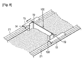
以下、図8を参照して前記のように構成される本発明の第1実施例に係る床施工装置を使用して施工面を処理する施工過程に対して説明する。
施工面にはセメントまたはアスファルトコンクリートが塗布されたりタイルまたは歩道ブロックが設置されたりするが、例えば、タイルを設置する作業の場合には、セメント、砂またはアスファルトコンクリートと水が混合された混合物を施工面に塗布し、施工面を平坦化した後、タイルを設置する湿式方式または砂が塗布された施工面を平坦化して所定の接着剤が塗布されたタイルを設置する乾燥式方式で進行される。
Hereinafter, with reference to FIG. 8, the construction process which processes a construction surface using the floor construction apparatus which concerns on 1st Example of this invention comprised as mentioned above is demonstrated.
Cement or asphalt concrete is applied to the construction surface, or tiles or sidewalk blocks are installed. After applying to the surface and flattening the construction surface, proceed with the wet method of installing tiles or the dry method of installing the tiles coated with a predetermined adhesive by flattening the construction surface with sand applied .
本発明に係る床施工装置は、砂、セメント、アスファルトコンクリートなどの物質を塗布した施工面を平坦化する装置であって、まず、砂、セメント、アスファルトコンクリートなどの物質が塗布された施工面に一対のレール21を所定間隔で配置させ、レール21の固定装置22を利用してレール21を施工面に固定させると共にレール21の施工面に対する勾配、例えばレール21の水平を調節する。このようにレール21を設置して水平を合せる過程で水平計を使用することが可能で、このような水平計はレール21に装着することができる。
A floor construction apparatus according to the present invention is an apparatus for flattening a construction surface coated with a substance such as sand, cement, and asphalt concrete. A pair of
レール21の設置が終了すると、プレート100が装着された平坦化ユニット10をレール21上に配置する。そして、図8に示したように、平坦化ユニット10を手動または自動でレール21に沿って移動させると、プレート100の移動によって砂、セメントまたはアスファルトコンクリートなどの物質が平坦化される。この時、物質が塗布された施工面を平坦化する間に発生する物質の残余分は、案内プレート14によってプレート100の両側へ移動せずプレート100の移動によって移動されながら除去される。
When the installation of the
そして、平坦化ユニット10によって平坦化された施工面にタイルを設置したり所定の追加作業を行った後、レール21及び平坦化ユニット10を施工面から撤去することによって、施工面を処理する施工過程を終了するようになる。
Then, after installing tiles on the construction surface flattened by the flattening
前記した本発明の第1実施例に係る床施工装置は、ガイドユニット20上の平坦化ユニット10を単に移動させる簡単な作業だけで大面積の施工面を平坦化することができるので、従来のように作業者が手作業によって施工することに比べて施工時間及び費用を低減することが可能で、欠陥補修による諸費用を画期的に節減し得るという効果がある。
The floor construction apparatus according to the first embodiment of the present invention can flatten a construction surface having a large area by simply moving the flattening
<第2実施例>
以下、図9及び図10を参照して本発明の第2実施例に係る床施工装置に関して説明する。本発明の第1実施例で説明した内容と同一部分に対しては同一図面符号を付して詳細な説明は省略する。
<Second embodiment>
Hereinafter, a floor construction apparatus according to a second embodiment of the present invention will be described with reference to FIGS. 9 and 10. The same parts as those described in the first embodiment of the present invention are designated by the same reference numerals, and detailed description thereof is omitted.
図9に示したように、本発明の第2実施例に係る床施工装置は、平坦化ユニット10に平坦化ユニット10のレール21に対する高低を調節する高さ調節装置18を包含して構成される。
As shown in FIG. 9, the floor construction apparatus according to the second embodiment of the present invention is configured to include a
図10に示したように、高さ調節装置18は、プレート100の両側に上下方向に長く形成された長孔119に挿入される締結部材191を通してプレート100に連結されてフレーム15の一方側面に固定される連結部材19と、プレート100の両側に固定されて内部に雌ねじ山が形成された孔を有する第1部材181と、第1部材181の孔に挿入され垂直方向に延長されて外周に雄ねじ山が形成される第2部材182と、を含んで構成される。第2部材182の上端には作業者の便宜上のハンドル183が備われ、第2部材182の下端はフレーム15に支持される。従って、締結部材191をプレート100の長孔119から解除した状態で、高さ調節装置18の第2部材182が回転すると、第1部材181とフレーム15間の間隔が調節されるので、平坦化ユニット10と施工面間の高さを調節することができる。
As shown in FIG. 10, the
更に、高さ調節装置18は平坦化ユニット10の両側に具備されるので、平坦化ユニット10の両方端の高低を個別的に調節することができる。従って、レール21の水平設置が円滑でない場所でレール21の水平を補完してより精密な水平合わせを行うことができる。また、レール21の設置面に対して施工面を所定角度に傾ける場合にも高さ調節装置18を利用することができる。
Furthermore, since the
一方、本発明の第2実施例では平坦化ユニット10の高さ調節装置18を手動操作する構成を提示したが、本発明はこのような構成に限定されず、油圧または空圧によって作動するシリンダーのように、平坦化ユニット10の高さを自動調節できる構成を適用することができる。
On the other hand, in the second embodiment of the present invention, a configuration in which the
本発明の第2実施例に係る床施工装置は、平坦化ユニット10のレール21に対する高さを調節する高さ調節装置18を具備するので、平坦化ユニット10と施工面間の間隔及び水平度を容易に調節することが可能で、作業の種類によって施工面に対する平坦化ユニット10の角度を調節し得るという効果がある。
Since the floor construction apparatus according to the second embodiment of the present invention includes the
<第3実施例>
以下、図11乃至図13を参照して本発明の第3実施例に係る床施工装置に関して説明する。本発明の第1実施例及び第2実施例で説明した内容と同一部分に対しては同じ図面符号を付して詳細な説明は省略する。
<Third embodiment>
Hereinafter, a floor construction apparatus according to a third embodiment of the present invention will be described with reference to FIGS. The same parts as those described in the first and second embodiments of the present invention are designated by the same reference numerals, and detailed description thereof is omitted.
図11に示したように、本発明の第3実施例に係る床施工装置は、平坦化ユニット10の移動を案内するガイドユニット20が、複数の第1レール410と、第1レール410上にスライド可能に配置される複数の第2レール420と、を含んで構成される。
As shown in FIG. 11, in the floor construction apparatus according to the third embodiment of the present invention, the
第1レール410は施工面に設置され、第2レール420には平坦化ユニット200が載置される。ここで、複数の第1レール410と複数の第2レール420は相互直交するように配置される。
The
第1レール410と第2レール420の間には、第2レール420が第1レール410上で円滑に移動できるように案内装置430が設置されることが好ましい。案内装置430は、本発明の第1実施例で説明したフレーム15のように、第1レール410と第2レール420間の摩擦を低減するように内部に少なくとも一つ以上の車輪が設置されることが好ましい。第2レール420は第1レール410上で手動移動され、本発明の第1実施例で提示した自動移動装置240を適用して自動移動することもできる。
A
一方、第1レール410には第1レール410を施工面に固定させる固定装置を具備することが可能で、この固定装置は本発明の第1実施例で説明した固定装置22と同様に施工面から第1レール410の高さを調節し得る構造を適用することができる。
On the other hand, the
このような構成によって、図12に示したように、複数の第2レール420がそれら間の幅(W)を一定に維持した状態で一緒に移動することが可能で、図13に示したように、複数の第2レール420がそれら間の幅(W)が減少または増加するように相互隣接する方向または離隔する方向へ個別的に移動することができる。
With such a configuration, as shown in FIG. 12, it is possible for the plurality of
前記のように構成される本発明の第3実施例に係る床施工装置は、平坦化ユニット10の移動を案内するガイドユニット20が相互直交するように配置される複数の第1レール410及び第2レール420により構成されるので、平坦化する施工面の面積に対応してレールの幅を自由に調節することができるという効果がある。
The floor construction apparatus according to the third embodiment of the present invention configured as described above includes a plurality of
<第4実施例>
以下、図14を参照して本発明の第4実施例に係る床施工装置に関して説明する。本発明の第1実施例乃至第3実施例で説明した内容と同一部分に対しては同一図面符号を付して詳細な説明は省略する。
<Fourth embodiment>
Hereinafter, a floor construction apparatus according to a fourth embodiment of the present invention will be described with reference to FIG. The same parts as those described in the first to third embodiments of the present invention are denoted by the same reference numerals, and detailed description thereof is omitted.
本発明の第4実施例に係る床施工装置は、平坦化ユニット10に脱着可能に設置される作業台600と、平坦化ユニット10に脱着可能に設置されて作業者が位置されるサドル700と、を含んで構成される。
The floor construction apparatus according to the fourth embodiment of the present invention includes a work table 600 that is detachably installed on the flattening
作業台600はフレーム15に設置され、または、フレーム15とフレーム15を連結する構造物上に設置される。作業台600上には施工作業に必要なタイル、仕上げ材または工具などの作業物610が在置される。従って、作業者は作業台600上の作業物610を容易に利用して底面の施工作業を遂行することができる。
The work table 600 is installed on the
サドル700はフレーム15に設置され、または、フレーム15とフレーム15を連結する構造物上に設置される。作業者はサドル700に座って片足でレール21を押しながら平坦化ユニット10を移動させることができるので、施工面の平坦化作業と同時に施工面にタイル、仕上げ材などを設置する施工作業を行うことができる。
The
本発明の第4実施例に係る床施工装置は、施工面に設置されるタイル、仕上げ材または工具などの作業物610が配置される作業台600と作業者が位置されるサドル700とが具備されるので、作業者の作業効率をより向上し得る効果がある。一方、本発明の第4実施例では作業台600とサドル700が具備される構造を提示しているが、本発明はこれに限定されず、作業台600またはサドル700中何れ一つだけを具備する構造を適用することもできる。
The floor construction apparatus according to the fourth embodiment of the present invention includes a work table 600 on which a work 610 such as a tile, a finishing material, or a tool installed on a construction surface is disposed, and a
<第5実施例>
以下、図15を参照して本発明の第5実施例に係る床施工装置に関して説明する。本発明の第1実施例乃至第4実施例で説明した内容と同一部分に対しては同一図面符号を付して詳細な説明は省略する。
<Fifth embodiment>
Hereinafter, a floor construction apparatus according to a fifth embodiment of the present invention will be described with reference to FIG. The same parts as those described in the first to fourth embodiments of the present invention are denoted by the same reference numerals, and detailed description thereof is omitted.
図15に示したように、本発明の第5実施例に係る床施工装置には、施工面に向かって水を噴射する給水装置800が具備される。 As shown in FIG. 15, the floor construction apparatus according to the fifth embodiment of the present invention includes a water supply apparatus 800 that injects water toward the construction surface.
給水装置800は、所定圧力を有して内部に水が貯蔵される給水ケース820と、施工面に向かって設置されて水が吐出されるノズル810と、給水ケース820とノズル810とを連結する連結管830と、を含んで構成される。
The water supply apparatus 800 connects a water supply case 820 having a predetermined pressure and storing water therein, a
給水ケース820及びノズル810は、フレーム15またはプレート100に連結されてフレーム15またはプレート100の移動によって移動される。図15ではノズル810がプレート100に連結された構成が提示される。ここで、プレート100にはノズル810が設置されるようにノズル装着部228が具備される。
The water supply case 820 and the
前記した本発明の第5実施例に係る床施工装置は、水を供給する給水装置800を一体具備することによって、施工面の平坦化作業と同時に施工面に水を供給することができるので、施工作業を容易に行うと同時に施工に必要とされる時間を短縮し得る効果がある。 The floor construction apparatus according to the fifth embodiment of the present invention described above can supply water to the construction surface simultaneously with the flattening operation of the construction surface by integrally including a water supply device 800 that supplies water. There is an effect that the construction work can be easily performed and the time required for the construction can be shortened.
<第6実施例>
以下、図16及び図17を参照して本発明の第6実施例に係る床施工装置に関して説明する。本発明の第1実施例乃至第5実施例で説明した内容と同じ部分に関しては同じ図面符号を付して詳細な説明は省略する。
<Sixth embodiment>
Hereinafter, a floor construction apparatus according to a sixth embodiment of the present invention will be described with reference to FIGS. 16 and 17. The same parts as those described in the first to fifth embodiments of the present invention are designated by the same reference numerals, and detailed description thereof is omitted.
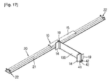
図16及び図17に示したように、本発明の第6実施例に係る床施工装置は、一つのレール21からなるガイドユニット20と、フレーム15を通して一つのレール21と連結されるプレート100を有する平坦化ユニット10と、を包含して構成される。
As shown in FIGS. 16 and 17, the floor construction apparatus according to the sixth embodiment of the present invention includes a
この場合、プレート100のレール21と連結される側の反対側を補完するために、図16に示したように、プレート100のレール21と連結される側の反対側には取っ手30が具備され、図17に示したように、プレート100に具備される支持体41及び支持体41に回転可能に連結されその外周面が施工面に接触する車輪42により構成される移動機構が設置される。
In this case, in order to complement the side opposite to the side connected to the
前記した本発明の第6実施例に係る床施工装置は、一つのレール21を利用して施工面を平坦化する作業を行うことができるので、複数のレール21を全て設置しきれない狭い面積の施工面を平坦化する作業を容易に実施することが可能で、レール21の数を減少させて費用も節減し得る効果がある。
Since the floor construction apparatus according to the sixth embodiment of the present invention described above can perform the work of flattening the construction surface using one
<第7実施例>
以下、図18及び図19を参照して本発明の第7実施例に係る床施工装置に関して説明する。本発明の第1実施例乃至第6実施例で説明した内容と同じ部分に関しては同じ図面符号を付して詳細な説明は省略する。
<Seventh embodiment>
Hereinafter, a floor construction apparatus according to a seventh embodiment of the present invention will be described with reference to FIGS. 18 and 19. The same parts as those described in the first to sixth embodiments of the present invention are designated by the same reference numerals, and detailed description thereof is omitted.
本発明の第7実施例に係る床施工装置において、ガイドユニット20のレール21は少なくとも一つの部門が折畳みできるように構成される。そのために、二つのレール21間には長孔を有する連結部材52と、連結部材52の長孔内に挿入されて二つのレール21を相互隣接した位置に固定させる連結ピン51と、を備えて構成される。
In the floor construction apparatus according to the seventh embodiment of the present invention, the
このような構成によって、図18及び図19に示したように、レール21は広まったり折畳まれたりすることができる。
With such a configuration, as shown in FIGS. 18 and 19, the
本発明の第7実施例に係る床施工装置は、レール21の運搬及び設置作業が容易になるという効果がある。
The floor construction apparatus according to the seventh embodiment of the present invention is advantageous in that the
<第8実施例>
以下、図20乃至図22を参照して、本発明の第8実施例に係る床施工装置に関して説明する。本発明の第1実施例乃至第7実施例で説明した内容と同じ部分に関しては同じ図面符号を付して詳細な説明は省略する。
<Eighth embodiment>
Hereinafter, a floor construction apparatus according to an eighth embodiment of the present invention will be described with reference to FIGS. The same parts as those described in the first to seventh embodiments of the present invention are denoted by the same reference numerals, and detailed description thereof is omitted.
図20に示したように、本発明の第8実施例に係る床施工装置は、ガイドユニット20のレール21が四角形の連続した形状に形成され、平坦化ユニット10はガイドユニット20の内部に配置された構成を有する。このような構成で、ガイドユニット20のレール21の下側には車輪231が具備されるので、ガイドユニット20は施工面上で移動することができる。また、作業者がガイドユニット20を容易に移動し得るように、レール21には取っ手24が連結される。
As shown in FIG. 20, in the floor construction apparatus according to the eighth embodiment of the present invention, the
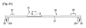
図21に示したように、レール21の下側と車輪231間には、車輪231のレール21の下側からの高さを調節する乗降装置25が具備される。このような乗降装置25を利用して車輪231のレール21からの高さを調節することができるので、ガイドユニット20の施工面に対する高さ及び施工面に対する角度を調節することができる。このような乗降装置25は、油圧または空圧によって作動するシリンダーのように、レール21の高さを自動調節できる構成が適用される。
As shown in FIG. 21, a boarding / alighting
更に、図22に示したように、レール21と車輪231間には車輪231を上側方向及び下側方向へ回転させるための回転装置28が具備される。このような、回転装置28の動作によって、車輪231がレール21の下側に位置する場合に車輪231を上側方向に回転させることで、レール21を直接施工面に支持させることが可能で、車輪231がレール21の上側に位置する場合、車輪231を下側方向へ回転させることによって、レール21を車輪231を通して施工面に支持させることができる。
Furthermore, as shown in FIG. 22, a
また、レール21の一方側には、施工面に対する水平程度を測定する水平計26が設置され、施工面に対する角度を測定する角度計27が設置される。
Further, on one side of the
本発明の第8実施例に係る床施工装置は、施工面上で移動可能で、レール21と車輪231間の高さを調節する乗降装置25を具備するので、施工面からの高さ及び角度を調節し得る効果がある。
The floor construction apparatus according to the eighth embodiment of the present invention is movable on the construction surface and includes the boarding /
<第9実施例>
以下、図23を参照して、本発明の第9実施例に係る床施工装置に関して説明する。本発明の第1実施例乃至第8実施例で説明した内容と同じ部分に関しては同じ図面符号を付して詳細な説明は省略する。
<Ninth embodiment>
Hereinafter, the floor construction apparatus according to the ninth embodiment of the present invention will be described with reference to FIG. The same parts as those described in the first to eighth embodiments of the present invention are denoted by the same reference numerals, and detailed description thereof is omitted.
図23に示したように、本発明の第9実施例に係る床施工装置は、平坦化ユニット10及びガイドユニット20の組立体を移動し得るように、ガイドユニット20が固定される移動ユニット60を備える。移動ユニット60には平坦化ユニット10及びガイドユニット20の組立体が複数連結される。
As shown in FIG. 23, the floor construction apparatus according to the ninth embodiment of the present invention is a moving
移動ユニット60の本体61には車輪611が具備され、ガイドユニット20と連結されてガイドユニット20を乗降させるリフト装置62が具備される。また、リフト装置62は、ガイドユニット20を所定の高さに持ち上げた状態でガイドユニット20を回転させる構成が適用される。移動ユニット60が移動する場合、リフト装置62が駆動してガイドユニット20が施工面から所定の高さを維持する。また、リフト装置62はガイドユニット20を回転させる構成が適用されるので、所定角度に傾斜した施工面に対して平坦化作業を行うことができる。
The
本発明の第9実施例に係る床施工装置は、平坦化ユニット10及びガイドユニット20の組立体を移動させる移動ユニット60が具備されるので、大面積の施工面に対する平坦化作業を容易に行うことができる。
Since the floor construction apparatus according to the ninth embodiment of the present invention includes the moving
<第10実施例>
以下、図24乃至図30を参照して、本発明の第10実施例に係る床施工装置に関して説明する。本発明の第1実施例乃至第9実施例で説明した内容と同じ部分に関しては同じ図面符号を付して詳細な説明は省略する。
<Tenth embodiment>
Hereinafter, a floor construction apparatus according to a tenth embodiment of the present invention will be described with reference to FIGS. The same parts as those described in the first to ninth embodiments of the present invention are denoted by the same reference numerals, and detailed description thereof is omitted.
図24に示したように、本発明の第10実施例に係る床施工装置は、プレート100の下側面に施工面に向かって開放される一つ以上のノッチ101が形成される。ノッチ101は施工面に砂、セメント、アスファルトコンクリートなどの物質が塗布された場合、このような物質上に所定の大きさ及び形状を有するリッジを形成する役割をする。
As shown in FIG. 24, in the floor construction apparatus according to the tenth embodiment of the present invention, one or
一方、プレート100の一面には施工面に塗布された物質の高さまたは平坦化高さを測定できる物差しを具備することが好ましい。このような構成によって作業者が作業途中で物差しを利用して平坦化高さを測定することができるので、施工過程上の平坦化不良などの問題を予め遮断することができる。
On the other hand, it is preferable that one surface of the
また、本発明の第10実施例に係る床施工装置は、図25に示したように、平坦化ユニット10に、プレート100に上下左右方向にスライド可能に設置されてプレート100のノッチ101の開放された形状を調節するサブプレート70を更に包含して構成される。
Further, as shown in FIG. 25, the floor construction apparatus according to the tenth embodiment of the present invention is installed on the flattening
サブプレート70は、その上下側がサブプレート70の長さ方向に直線形状を有する構成が適用されるが、本発明はこれに限定されず、サブプレート70にはその幅方向の一方側に向かって開放される一つ以上のスリット71が形成される。
The
サブプレート70は、プレート100を基準に上下方向または左右方向へ移動しながらプレート100のノッチ101の形状を調節する。
The
サブプレート70がプレート100に上下方向へ移動可能に設置されるようにサブプレート70には上下方向に延長される長孔73が形成され、プレート100にはサブプレート70の長孔73に対応する貫通孔103が形成される。サブプレート70の長孔73及びプレート100の貫通孔103には締結部材320が挿入され、それによってサブプレート70が所定の上下方向位置を維持した状態でプレート100に固定される。
A
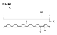
従って、図26に示したように、サブプレート70はプレート100に対して上下方向へ移動可能で、サブプレート70が下側方向へ移動する分だけプレート100のノッチ101の開放面積が縮小されるので、ノッチ101の形状を調節することができる。一方、図27に示したように、サブプレート70はスリット71が形成されてない面が下側に位置するようにプレート100に装着され、プレート100に対して上下方向への位置を調節することによってプレート100のノッチ101の開放形状を調節することができる。
Therefore, as shown in FIG. 26, the
また、サブプレート70がプレート100に左右方向へ移動可能に設置されるようにサブプレート70には左右方向に延長される長孔74が形成され、プレート100にはサブプレート70の長孔74に対応する貫通孔104が形成される。サブプレート70の長孔74及びプレート100の貫通孔104には締結部材330が挿入されて、よって、サブプレート70が所定の左右方向位置を維持した状態でプレート100に固定される。
Further, a
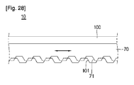
従って、図28に示したように、サブプレート70はプレート100に対して左右方向へ移動可能であるので、サブプレート70の左右方向の位置を調節することによってプレート100のノッチ222の開放形状を調節することができる。
Therefore, as shown in FIG. 28, the
前記したように構成される平坦化ユニット10は、プレート100に関して上下方向または左右方向へ移動可能に設置されるサブプレート70を備え、サブプレート70の上下方向または左右方向の位置を調節しながらプレート100のノッチ101の開放形状を調節することができるので、施工面の施工作業の種類に応じて施工面に形成されるパターン、例えば、リッジの形状などを多様に調節できる効果がある。
The flattening
一方、図29に示したように、平坦化ユニット10のプレート100は、第1プレート110と、第1プレート110に長さ方向へ移動可能に連結される第2プレート120と、を備えて構成される。第1プレート110及び第2プレート120は各々他のフレーム15に連結され、長さ方向に延長される各長孔111、121が形成される。第1プレート110及び第2プレート120の各長孔111、112には所定の締結部材340が挿入されるので、第1プレート110と第2プレート120は相互連結される。
On the other hand, as shown in FIG. 29, the
したがって、図30に示したように、第1プレート110及び第2プレート120の長さ方向への相対的な位置によってプレート100の全体長さが変化される。即ち、第1プレート110と第2プレート120が相互重なる面積が大きくなる方向へ移動する場合はプレート100の長さが順次減少され、その反対の場合にはプレート100の長さが増加する。
Therefore, as shown in FIG. 30, the overall length of the
一方、本発明ではプレート100が第1プレート110及び第2プレート120の二つに具備される構成を提示したが、本発明はこれに限定されず、プレート100が二つ以上の複数に構成されることもできる。
Meanwhile, in the present invention, the configuration in which the
前記のように構成される平坦化ユニット10は、プレート100が複数のプレート110、120が相互長さ方向へ相対変位できるように設置された構造により構成されるので、プレート100の長さを容易に調節することができる。従って、施工面の面積によってレール21の幅が変化する場合、多様な長さを有する複数のプレートを具備してレール21間の幅に対応して複数のプレートを交替するといった短所が解決される。
Since the flattening
前記の通りに構成される平坦化ユニット10は、プレート100が施工面に位置した状態で、作業者がプレート100の一方側または両方側を把持した後、施工面上でプレート100を移動させながら施工面の平坦化作業を行う。
In the state where the
本発明に係る床施工装置は、多様な形状を有するノッチ101が形成された複数のプレート100を備え、作業者が作業の種類に応じて複数のプレート100を交替しながら作業を行うことができる。
The floor construction apparatus according to the present invention includes a plurality of
このような、本発明の第10実施例に係る床施工装置の平坦化ユニット10は、第1実施例乃至第9実施例で説明したガイドユニット20に設置され、即ち、平坦化ユニット10はガイドユニット20に案内されて移動しながら施工面を平坦化する。
The flattening
<第11実施例>
以下、図31乃至図43を参照して、本発明の第11実施例に係る床施工装置に関して説明する。
<Eleventh embodiment>
Hereinafter, a floor construction apparatus according to an eleventh embodiment of the present invention will be described with reference to FIGS. 31 to 43.
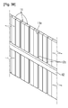
図31及び図32に示したように、本発明の第11実施例に係る床施工装置は、平坦化ユニット10が、施工面に塗布された物質を平坦化するために一列に配置される複数のプレート11と、複数のプレート11が配置される方向へ延長されて複数のプレート11を支持して複数のプレート11の配置形状を維持する支持部材12と、支持部材12の位置を固定させる固定部材13と、を含んで構成される。
As shown in FIGS. 31 and 32, in the floor construction apparatus according to the eleventh embodiment of the present invention, a plurality of flattening
複数のプレート11は各々平板状に形成されて、各プレート11の狭い面が隣接するプレート11に連結される形態で配置される。各プレート11の長さ及び幅は施工面の種類に応じて適切に変更される。一方、本発明は複数のプレート11が平板状に形成されることに限定されず、複数のプレート11はその水平方向への断面形状が三角形、多角形、円形または流線型の形状に形成される。このような複数のプレート11の水平方向への断面形状は、物質を施工面に塗布する過程で圧力を分散できるように適切に選択される。
The plurality of
図33に示したように、複数のプレート11が相互連結される両側部分には突出部11a及び凹溝部11bが形成される。従って、何れか一つのプレート11の突出部11aが隣接するプレート11の凹溝部11bに挿入される方式で複数のプレート11が相互連結される。このような構成によって複数のプレート11が前方側へ移動しながら施工面に塗布された物質を平坦化する過程で、複数のプレート11が配置された形状を一層堅固に維持させる。
As shown in FIG. 33, a protruding
また、図34及び図35に示したように、複数のプレート11の各下端部113は施工面に塗布された物質に接触する部分の面積が大きく形成される。即ち、図34に示したように、複数のプレート11は各下端部113へ行くほど厚さが順次増加する形状に形成され、図35に示したように、複数のプレート11の各下端部113はプレート11の一面から水平方向へ延長される。即ち、プレート11の下端部113は、プレート11の一面と形成する角度がほぼ直角になるように延長されて、プレート11の形状がアルファベット“L”字状になる。このような構成によって複数のプレート11が施工面と接触する面積を大きくなるようにして施工面をより均一に平坦化させる。
Further, as shown in FIGS. 34 and 35, each
また、図36に示したように、プレート11の下端部113の施工面に対向する面、即ち、施工面と接触する面には所定の溝113aが形成される。このような溝113aの形成によってプレート11と施工面間の圧力による摩擦を低減することが可能で、従って、プレート11を施工面に対して円滑に移動させることができる。
Further, as shown in FIG. 36, a
一方、複数のプレート11は、支持部材12及び固定部材13による固定が解除された場合、複数のプレート11は各々個別的に上下方向へ位置調節される。従って、平坦化される施工面の高低に合せてプレート11の上下方向への位置調節を行って、施工面に塗布された物質を施工面の高低に合せて平坦化することができる。このように、複数のプレート11は個別的に上下方向への位置が調節されるが、各プレート11の上下方向への調節位置を正確に判断できるように、図37に示したように、各プレート11の少なくとも一面には上下方向に目盛り114が形成されることが好ましい。
On the other hand, when the plurality of
支持部材12は、複数のプレート11の配置方向に延長されて複数のプレート11が相互連結された形態の全体幅に対応する長さを有する。支持部材12は、複数のプレート11の前方側面及び後方側面に各々一つ以上配置され、支持部材12の一面は複数のプレート11の前方側面及び後方側面に密着される。支持部材12は磁石で形成され、従って、複数のプレート11の前方側面に配置された支持部材12と後方側面に配置された支持部材12が磁力によって相互引っ張るようにして複数のプレート11の配置形状を維持させる。
The
一方、図38に示したように、各プレート11にはプレート11の長さ方向に延長される溝11cが形成され、支持部材12の複数のプレート11に密着される面にはプレート11の溝11cに対応する形状の突起12cが形成される。このような構成によって、支持部材12が複数のプレート11の前方側面及び後方側面を密着する時、プレート11の溝に支持部材12の突起12cが挿入されることによって、支持部材12が複数のプレート11をより堅固に支持することができる。一方、本発明は前記したような構成に限定されず、支持部材12に溝が形成されプレート11にその長さ方向に延長されて支持部材12の溝に挿入される突起が形成される構成を適用することができる。
On the other hand, as shown in FIG. 38, a
固定部材13は、複数のプレート11の前方側及び後方側に配置されて、支持部材12を複数のプレート11の前方側面及び後方側面に密着させた状態で固定する役割をする。このような固定部材13は、ほぼプレート11の長さ方向に延長され、支持部材12が複数のプレート11の前方側面及び後方側面を加圧する方向に締結される。固定部材13の締結のためには固定部材13及びプレート11を貫通するねじ131が具備される。
The fixing
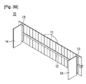
図39に示したように、固定部材13には、施工面の平坦化過程中で施工面に塗布された物質の残余分がプレートの一方側へ移動することを防止するように、固定部材13から延長される案内プレート14が具備される。案内プレート14は、一端が固定部材13に固定されて、他端はプレート11のほぼ垂直方向、即ち、プレート11が移動する前方側方向へ延長される。ただし、本発明はこのような構成に限定されず、プレート11の一面と案内プレート14の一面が形成する角度が直角になり、施工条件によって鋭角または鈍角になるように構成することができる。また、案内プレート14がプレート11の一面に固定される構成を適用することもできる。案内プレート14間の空間には複数のプレート11が移動しながら砂、セメント、アスファルトコンクリートなどの物質が塗布された施工面を平坦化する間、物質の残余分が存在する。したがって、案内プレート14は物質の残余分が複数のプレート11の両側へ移動することを防止しながら物質の残余分を除去する役割を行う。案内プレート14は複数のプレート11の配置形状に沿ってほぼ一定の間隔で複数設置されることが好ましい。このような場合複数の案内プレート14が形成する空間に物質の残余分が等しく分配されるので、複数のプレート11の移動時に発生する抵抗を低減することができる。
As shown in FIG. 39, the fixing
前記の通りに構成される平坦化ユニット10は、複数のプレート11が施工面に位置された状態で移動しながら施工面の平坦化作業を行う。ここで、平坦化ユニット10は、複数のプレート11が個別的に上下方向に位置調節される。したがって、図40に示したように、施工される面の高低を少しずつ変化させる場合と、図41に示したように、施工される面内に段差部を形成させる場合、複数のプレート11の上下方向位置(H)を調節して、平坦化ユニット10の下の面が形成する形状を調節することによって、設計に適合した形状の施工面を形成することができる。
The flattening
一方、図42に示したように、プレート11の前方側または後方側にはプレート11の長さよりも長くプレート11の幅よりも大きい幅を有する基準プレート16を更に備える。基準プレート16は、複数のプレート11の一方側に配置され、複数のプレート11が連結された形態の幅と対応されて、複数のプレート11が連結された形態の高さよりも高い。このような基準プレート16の複数のプレート11に対向する面には垂直及び水平方向への目盛り161が形成される。このような構成によって複数のプレート11中一つ以上のプレート11の高さが調節される場合、基準プレート16の目盛り161を利用してプレート11の上下方向高さ及び長さがどの程度調節されたかを正確に測定することが可能で、測定された高さからプレート11とプレート11間の高さ差及び角度を測定することができる。
On the other hand, as shown in FIG. 42, a
一方、図43に示したように、作業者が複数のプレート11を移動させる力を低減し得るように、複数のプレート11の両側には複数のプレート11を移動させるための移動機構が具備されることが好ましく、このような移動機構は、複数のプレート11の両側に具備される支持体116と、支持体116に回転可能に連結されてその外周面が施工面に接触する車輪117と、を含んで構成される。かつ、作業者が平坦化ユニット10を容易に移動させるように移動機構には取っ手17が連結されることが好ましい。このような構成によって、作業者は車輪117の回転を通して複数のプレート11を小力で移動し得るので、施工面の平坦化作業を容易に行って施工時間を短縮させる効果がある。
On the other hand, as shown in FIG. 43, a moving mechanism for moving the plurality of
このような、本発明の第11実施例に係る床施工装置の平坦化ユニット10は、第1実施例乃至第9実施例で説明したガイドユニット20に設置することが可能で、これに従って、平坦化ユニット10はガイドユニット20に案内されて移動しながら施工面を平坦化する。
The flattening
本発明に係る床施工装置は、建物の室内の施工面及び道路や歩道のような室外の施工面を平坦化する作業に適用することが可能で、建物の内壁及び外壁を平坦化する作業にも適用される。 The floor construction apparatus according to the present invention can be applied to an operation for flattening an indoor construction surface of a building and an outdoor construction surface such as a road or a sidewalk, and for an operation of flattening an inner wall and an outer wall of a building. Also applies.
10 ・・・平坦化ユニット
14 ・・・案内プレート
15 ・・・フレーム
19 ・・・連結部材
20 ・・・ガイドユニット
21 ・・・レール
22 ・・・固定装置
100・・・プレート
DESCRIPTION OF
Claims (27)
前記施工面上での前記平坦化ユニットの移動を案内するガイドユニットと、
を包含することを特徴とする、床施工装置。 A flattening unit comprising a plate whose lower edge contacts the material applied to the construction surface for planarization of the construction surface;
A guide unit for guiding the movement of the flattening unit on the construction surface;
The floor construction apparatus characterized by including.
前記平坦化ユニットは、前記プレートにスライド可能に設置されて前記プレートのノッチの開放された形状を調節するサブプレートを更に含むことを特徴とする、請求項1記載の床施工装置。 The lower edge of the plate is formed with a notch that is open to the construction surface,
The floor construction apparatus according to claim 1, wherein the flattening unit further includes a sub-plate that is slidably installed on the plate and adjusts an open shape of the notch of the plate.
第1プレートと、
前記第1プレートに長さ方向へ移動可能に連結される第2プレートと、を含むことを特徴とする、請求項1記載の床施工装置。 The plate is
A first plate;
The floor construction apparatus according to claim 1, further comprising a second plate coupled to the first plate so as to be movable in a length direction.
前記平坦化ユニットには、前記レール上に移動可能に配置されて前記平坦化ユニットと連結されるフレームが具備されることを特徴とする、請求項1記載の床施工装置。 The guide unit is composed of one or more rails,
The floor construction apparatus according to claim 1, wherein the flattening unit includes a frame that is movably disposed on the rail and connected to the flattening unit.
前記施工面に設置される少なくとも一つの第1レールと、
前記第1レール上にスライド可能に配置されて、前記平坦化ユニットが載置される少なくとも一つの第2レールと、
を含むことを特徴とする、請求項5記載の床施工装置。 The rail is
At least one first rail installed on the construction surface;
At least one second rail, slidably disposed on the first rail, on which the flattening unit is mounted;
The floor construction apparatus according to claim 5, comprising:
前記平坦化ユニットは前記フレームを通して前記一つのレールと連結され、前記平坦化ユニットの前記レールと連結される側の反対側には取っ手が具備されることを特徴とする、請求項5記載の床施工装置。 The guide unit is composed of one rail,
The floor according to claim 5, wherein the flattening unit is connected to the one rail through the frame, and a handle is provided on an opposite side of the flattening unit to a side connected to the rail. Construction equipment.
前記平坦化ユニットは前記フレームを通して前記一つのレールと連結され、前記平坦化ユニットの前記レールと連結される側の反対側には車輪が具備されることを特徴とする、請求項5記載の床施工装置。 The guide unit is composed of one rail,
The floor according to claim 5, wherein the flattening unit is connected to the one rail through the frame, and a wheel is provided on the opposite side of the flattening unit to the side connected to the rail. Construction equipment.
前記平坦化ユニットは、前記複数のプレートが配置される方向に延長され、それら複数のプレートを支持してそれら複数のプレートの配置形状を維持する支持部材と、前記支持部材の位置を固定させる固定部材と、を含むことを特徴とする、請求項1記載の床施工装置。 The plate is composed of a plurality of plates arranged in a row,
The flattening unit is extended in the direction in which the plurality of plates are arranged, supports the plurality of plates, and maintains the arrangement shape of the plurality of plates, and fixing that fixes the position of the support member The floor construction apparatus according to claim 1, comprising a member.
前記支持部材には、前記複数のプレートの溝に挿入される突起が形成されることを特徴とする、請求項21記載の床施工装置。 In the plurality of plates, grooves extending in the length direction of the plurality of plates are formed,
The floor construction apparatus according to claim 21, wherein the support member is formed with a protrusion inserted into a groove of the plurality of plates.
前記基準プレートの前記複数のプレートに対向する面には目盛りが形成されることを特徴とする、請求項21記載の床施工装置。 On one side of the plurality of plates, a reference plate higher than the height of the form in which the plurality of plates are connected is provided,
The floor construction apparatus according to claim 21, wherein a scale is formed on a surface of the reference plate facing the plurality of plates.
Applications Claiming Priority (7)
| Application Number | Priority Date | Filing Date | Title |
|---|---|---|---|
| KR20080088878 | 2008-09-09 | ||
| KR10-2008-0088878 | 2008-09-09 | ||
| KR1020080134275A KR100922331B1 (en) | 2008-09-09 | 2008-12-26 | Apparatus for constructing floor of building |
| KR10-2008-0134275 | 2008-12-26 | ||
| KR1020090084516A KR101120050B1 (en) | 2009-09-08 | 2009-09-08 | Apparatus for constructing floor |
| KR10-2009-0084516 | 2009-09-08 | ||
| PCT/KR2009/005114 WO2010030117A2 (en) | 2008-09-09 | 2009-09-09 | Floor construction apparatus |
Publications (1)
| Publication Number | Publication Date |
|---|---|
| JP2012502204A true JP2012502204A (en) | 2012-01-26 |
Family
ID=42005624
Family Applications (1)
| Application Number | Title | Priority Date | Filing Date |
|---|---|---|---|
| JP2011525996A Pending JP2012502204A (en) | 2008-09-09 | 2009-09-09 | Floor construction equipment |
Country Status (7)
| Country | Link |
|---|---|
| US (1) | US8684717B2 (en) |
| EP (1) | EP2327845A2 (en) |
| JP (1) | JP2012502204A (en) |
| AU (1) | AU2009292322A1 (en) |
| CA (1) | CA2747849A1 (en) |
| MX (1) | MX2011002517A (en) |
| WO (1) | WO2010030117A2 (en) |
Cited By (1)
| Publication number | Priority date | Publication date | Assignee | Title |
|---|---|---|---|---|
| JP6019462B1 (en) * | 2016-04-01 | 2016-11-02 | 有限会社安藤建装 | Slope construction method |
Families Citing this family (16)
| Publication number | Priority date | Publication date | Assignee | Title |
|---|---|---|---|---|
| US9309680B2 (en) | 2012-01-12 | 2016-04-12 | Ooparts Asia Pte., Ltd. | Forming device and construction method using forming device |
| US9499994B2 (en) * | 2012-11-01 | 2016-11-22 | Propst Family Limited Partnership | Tools for applying coatings and method of use |
| US20140314482A1 (en) * | 2013-04-17 | 2014-10-23 | Rfvc Associates, Inc. | Forms and screed for paving materials |
| CN103962267A (en) * | 2014-04-23 | 2014-08-06 | 天津金禹融通生物科技有限公司 | Gumming device capable of being applied to gumming machine |
| CN104372916B (en) * | 2014-11-26 | 2016-08-17 | 夏江 | The sand-lime tiling device of floor tile |
| USD795031S1 (en) * | 2015-02-12 | 2017-08-22 | Bricky Mate Limited | Mortar guide |
| US10156048B1 (en) * | 2017-03-28 | 2018-12-18 | Chad Springborg | Boom screed chemical sprayer system for paving |
| CN108222517A (en) * | 2018-03-01 | 2018-06-29 | 苏州市越吴建筑机械有限公司 | A kind of mattess apparatus for leveling |
| CN108571154A (en) * | 2018-03-13 | 2018-09-25 | 上海相品家居建材有限公司 | Assembled tile installation method and tool |
| CN108505448A (en) * | 2018-04-30 | 2018-09-07 | 安徽省公路桥梁工程有限公司 | Pier cap beam anchor ear girder steel template system and its construction method |
| CN111119459B (en) * | 2019-12-09 | 2021-11-05 | 王勇 | Cement leveling device |
| CN111236599B (en) * | 2020-03-05 | 2021-08-31 | 广东博智林机器人有限公司 | Leveling execution device and leveling robot |
| KR102303265B1 (en) * | 2020-05-06 | 2021-09-17 | 주식회사 고도에스티 | the method of constructing terrazo |
| US11686113B2 (en) * | 2021-02-17 | 2023-06-27 | Paul Gomez | Concrete finishing assembly |
| CN114319879B (en) * | 2022-01-25 | 2023-06-06 | 中厦建设集团有限公司 | Cement floor leveling device for house building |
| CN115450433A (en) * | 2022-09-01 | 2022-12-09 | 中国建筑第五工程局有限公司 | Flatness control equipment is pour in piecemeal to floor slab post-cast strip |
Citations (10)
| Publication number | Priority date | Publication date | Assignee | Title |
|---|---|---|---|---|
| JPS5125521U (en) * | 1974-08-15 | 1976-02-25 | ||
| JPS5221151U (en) * | 1975-07-31 | 1977-02-15 | ||
| JPS6098004A (en) * | 1983-11-04 | 1985-06-01 | 東急建設株式会社 | Invert slide type frame apparatus |
| JPS6294653A (en) * | 1985-10-21 | 1987-05-01 | 島袋 良信 | Floor concrete leveling machine |
| JPH0288805A (en) * | 1988-09-26 | 1990-03-29 | Maeda Road Constr Co Ltd | Concrete leveler |
| JPH03202172A (en) * | 1989-12-28 | 1991-09-03 | Chugoku Marine Paints Ltd | Device for applying level coat to floor board |
| JPH0641914A (en) * | 1992-07-23 | 1994-02-15 | Mitsui Toatsu Chem Inc | Execution method and apparatus for elastic pavement material |
| JPH07229300A (en) * | 1994-02-16 | 1995-08-29 | Tokai Purekon Kk | Base surface leveller and method of construction levelling base surface |
| JP2002069921A (en) * | 2000-08-24 | 2002-03-08 | Yoshihiko Kobayashi | Road surface leveling device for work |
| JP2004160268A (en) * | 2002-11-08 | 2004-06-10 | Matsushita Electric Works Ltd | Iron for applying adhesive |
Family Cites Families (22)
| Publication number | Priority date | Publication date | Assignee | Title |
|---|---|---|---|---|
| US50146A (en) * | 1865-09-26 | Improvement in apparatus for enameling moldings | ||
| US2273599A (en) * | 1939-01-30 | 1942-02-17 | Bird & Son | Machine for applying roofing material |
| US2683297A (en) * | 1950-09-05 | 1954-07-13 | Atlas Products Overseas Ltd | Apparatus for the manufacture of roofing tiles and the like |
| US2763019A (en) * | 1953-08-11 | 1956-09-18 | Huber Frank | Floor treating apparatus |
| CA933729A (en) * | 1971-08-06 | 1973-09-18 | D. Paton William | Concrete finishing method and machine |
| JPS5221151A (en) | 1975-08-09 | 1977-02-17 | Iony Kk | Reciprocating separator for grain |
| US4804321A (en) * | 1988-04-18 | 1989-02-14 | Armando Riesgo | Spreader tool for cementitious mix |
| US4873738A (en) * | 1988-09-29 | 1989-10-17 | Cfc Fabrication Corporation | Apparatus for stripping concrete forms from bridge structures |
| US5302051A (en) * | 1992-01-16 | 1994-04-12 | Koter Industries, Inc. | Applicator blade assembly for resurfacing apparatus |
| US5807022A (en) * | 1995-02-10 | 1998-09-15 | Mccleary Concepts And Creations, Inc. | Combination mortar and grout spreading device |
| US5768793A (en) * | 1996-09-09 | 1998-06-23 | Fields; Timothy S. | Adjustable template for laying tiles and method |
| US6071458A (en) * | 1997-06-30 | 2000-06-06 | Port-O-Wall Systems, Llc | System for shaping the surface of pre-cast concrete panels |
| US6102615A (en) * | 1997-11-17 | 2000-08-15 | Wilson, Sr.; Jack H. | Pavement and tennis court coating machine |
| US5980154A (en) * | 1998-03-09 | 1999-11-09 | Record; Darren D. | Manual screeding system |
| US6412185B1 (en) * | 2000-07-07 | 2002-07-02 | Oscar Mills | Tile laying gauge and leveling assembly |
| US20070277475A1 (en) * | 2002-12-28 | 2007-12-06 | Smythe Timothy E | Drywall mud hopper for inside and outside corners |
| US20070266937A1 (en) * | 2003-10-31 | 2007-11-22 | Giovanni Fascianella | Device for Spreading Adhesive |
| WO2005097476A2 (en) * | 2004-04-02 | 2005-10-20 | Z Corporation | Methods and apparatus for 3d printing |
| US6907908B1 (en) * | 2004-04-30 | 2005-06-21 | Pla-Cor Incorporated | Hopper apparatus and method for application of joint compound to corner beads |
| US7213296B2 (en) * | 2004-07-06 | 2007-05-08 | Billy Star Holding Ltd | Spreading apparatus for flowable materials and spreader pad therefor |
| JP4889336B2 (en) * | 2006-03-27 | 2012-03-07 | 株式会社タジマ | Combing |
| DE102006023031A1 (en) * | 2006-05-10 | 2007-11-15 | Carl Zeiss Industrielle Messtechnik Gmbh | Method and device for probing a surface point on a workpiece |
-
2009
- 2009-09-09 CA CA2747849A patent/CA2747849A1/en not_active Abandoned
- 2009-09-09 JP JP2011525996A patent/JP2012502204A/en active Pending
- 2009-09-09 AU AU2009292322A patent/AU2009292322A1/en not_active Abandoned
- 2009-09-09 MX MX2011002517A patent/MX2011002517A/en not_active Application Discontinuation
- 2009-09-09 EP EP09813239A patent/EP2327845A2/en not_active Withdrawn
- 2009-09-09 WO PCT/KR2009/005114 patent/WO2010030117A2/en active Application Filing
- 2009-09-09 US US12/741,072 patent/US8684717B2/en active Active
Patent Citations (10)
| Publication number | Priority date | Publication date | Assignee | Title |
|---|---|---|---|---|
| JPS5125521U (en) * | 1974-08-15 | 1976-02-25 | ||
| JPS5221151U (en) * | 1975-07-31 | 1977-02-15 | ||
| JPS6098004A (en) * | 1983-11-04 | 1985-06-01 | 東急建設株式会社 | Invert slide type frame apparatus |
| JPS6294653A (en) * | 1985-10-21 | 1987-05-01 | 島袋 良信 | Floor concrete leveling machine |
| JPH0288805A (en) * | 1988-09-26 | 1990-03-29 | Maeda Road Constr Co Ltd | Concrete leveler |
| JPH03202172A (en) * | 1989-12-28 | 1991-09-03 | Chugoku Marine Paints Ltd | Device for applying level coat to floor board |
| JPH0641914A (en) * | 1992-07-23 | 1994-02-15 | Mitsui Toatsu Chem Inc | Execution method and apparatus for elastic pavement material |
| JPH07229300A (en) * | 1994-02-16 | 1995-08-29 | Tokai Purekon Kk | Base surface leveller and method of construction levelling base surface |
| JP2002069921A (en) * | 2000-08-24 | 2002-03-08 | Yoshihiko Kobayashi | Road surface leveling device for work |
| JP2004160268A (en) * | 2002-11-08 | 2004-06-10 | Matsushita Electric Works Ltd | Iron for applying adhesive |
Cited By (1)
| Publication number | Priority date | Publication date | Assignee | Title |
|---|---|---|---|---|
| JP6019462B1 (en) * | 2016-04-01 | 2016-11-02 | 有限会社安藤建装 | Slope construction method |
Also Published As
| Publication number | Publication date |
|---|---|
| US8684717B2 (en) | 2014-04-01 |
| CA2747849A1 (en) | 2010-03-18 |
| US20120279169A1 (en) | 2012-11-08 |
| AU2009292322A1 (en) | 2010-03-18 |
| MX2011002517A (en) | 2011-07-20 |
| EP2327845A2 (en) | 2011-06-01 |
| WO2010030117A2 (en) | 2010-03-18 |
| WO2010030117A3 (en) | 2010-06-24 |
Similar Documents
| Publication | Publication Date | Title |
|---|---|---|
| JP2012502204A (en) | Floor construction equipment | |
| KR101643551B1 (en) | The wall auto spread machine and method for spreading wall using this same | |
| KR20110115629A (en) | Application equipment for putty | |
| KR101100258B1 (en) | Wall solid plastering device and wall solid plastering machine using the same | |
| CN103352557B (en) | Drone version full-automatic multi-functional wall surface mortar strikes off trowelling machine | |
| CN106013746A (en) | Outer wall stone-like paint spraying device | |
| KR100922331B1 (en) | Apparatus for constructing floor of building | |
| CN202577910U (en) | Facing machine for building | |
| CN102605937A (en) | Architectural coating machine | |
| EP2694756A1 (en) | Screeding machine for leveling floor bases | |
| CN103334578A (en) | Semi-automatic multi-functional wall space mortar scraping screeding machine | |
| KR100728712B1 (en) | A fixing device for a out side panel | |
| KR101120050B1 (en) | Apparatus for constructing floor | |
| CN203452347U (en) | Full-automatic multifunctional remote control type wall space mortar scraping and trowelling machine | |
| KR20210002301A (en) | Sludge-type mortar with a plaster finish on the screed vibration dapple bar | |
| CN205857639U (en) | Exterior wall true stone paint spray equipment | |
| CN215329220U (en) | Construction is with supplementary tile work device | |
| KR101059862B1 (en) | Exterior panel fixing device of building | |
| JP7179359B2 (en) | floor construction machine | |
| CN203452351U (en) | Wall mortar leveling device | |
| CN204509962U (en) | A kind of brick paving machine | |
| CN210508277U (en) | Trowelling device | |
| CN203430000U (en) | Multifunctional steel wire quick movable elevation bar | |
| CN210289026U (en) | Automatic plastering trowelling machine | |
| JP2001159240A (en) | Concrete direct finishing method and jig |
Legal Events
| Date | Code | Title | Description |
|---|---|---|---|
| A977 | Report on retrieval |
Free format text: JAPANESE INTERMEDIATE CODE: A971007 Effective date: 20121029 |
|
| A131 | Notification of reasons for refusal |
Free format text: JAPANESE INTERMEDIATE CODE: A131 Effective date: 20121106 |
|
| A02 | Decision of refusal |
Free format text: JAPANESE INTERMEDIATE CODE: A02 Effective date: 20130402 |