JP2012245122A - Movable performance device of game machine - Google Patents

Movable performance device of game machine Download PDF

Info

Publication number
JP2012245122A
JP2012245122A JP2011118527A JP2011118527A JP2012245122A JP 2012245122 A JP2012245122 A JP 2012245122A JP 2011118527 A JP2011118527 A JP 2011118527A JP 2011118527 A JP2011118527 A JP 2011118527A JP 2012245122 A JP2012245122 A JP 2012245122A
Authority
JP
Japan
Prior art keywords
side decoration
movable
character
fixed
decoration
Prior art date
Legal status (The legal status is an assumption and is not a legal conclusion. Google has not performed a legal analysis and makes no representation as to the accuracy of the status listed.)
Granted
Application number
JP2011118527A
Other languages
Japanese (ja)
Other versions
JP5477337B2 (en
Inventor
Sei Kamisaka
聖 上坂
Current Assignee (The listed assignees may be inaccurate. Google has not performed a legal analysis and makes no representation or warranty as to the accuracy of the list.)
Okumura Yu Ki Co Ltd
Original Assignee
Okumura Yu Ki Co Ltd
Priority date (The priority date is an assumption and is not a legal conclusion. Google has not performed a legal analysis and makes no representation as to the accuracy of the date listed.)
Filing date
Publication date
Application filed by Okumura Yu Ki Co Ltd filed Critical Okumura Yu Ki Co Ltd
Priority to JP2011118527A priority Critical patent/JP5477337B2/en
Publication of JP2012245122A publication Critical patent/JP2012245122A/en
Application granted granted Critical
Publication of JP5477337B2 publication Critical patent/JP5477337B2/en
Expired - Fee Related legal-status Critical Current
Anticipated expiration legal-status Critical

Links

Images

Abstract

PROBLEM TO BE SOLVED: To provide a movable performance device of a game machine, which can impart a novel expression to a game player.SOLUTION: The movable performance device comprises: a left fixed part 150 and a right fixed part 160 which are applied with left fixed-side decoration 151 and right fixed-side decoration 161, respectively; and a movable part 130 which is applied with left movable-side decoration 135L and right movable-side decoration 135R, and movable in the vertical direction in front of the left fixed-side part 150 and the right fixed part 160. When the movable part 130 is in a first relative position in which the movable part overlaps with respect to the left fixed-side decoration 151 or the like, a first character is constituted of the left movable-side decoration 135L, the right movable-side decoration 135R, the left fixed-side decoration 151 and the right fixed-side decoration 161; and when the movable part 130 is in a second relative position in which the movable part is moved from the first relative position, a second character different from the first character is constituted of the left fixed-side decoration 151 and the right fixed-side decoration 161.

Description

本発明は、装飾が施された可動部を移動させて演出を行う遊技機の可動演出装置の技術に関する。   The present invention relates to a technique for a movable effect device for a gaming machine that performs an effect by moving a decorated movable part.

従来、装飾が施された可動部を移動させて演出を行う遊技機の可動演出装置の技術は公知となっている。例えば、特許文献1に記載の如くである。   2. Description of the Related Art Conventionally, a technique for a movable effect device for a gaming machine that performs an effect by moving a decorated movable part has been publicly known. For example, as described in Patent Document 1.

特許文献1に記載の技術では、遊技盤に固定されるとともに前面に装飾が施された装飾枠(固定部)に対して、前面に装飾が施された落下部材(可動部)が上下方向に往復移動自在となるように配置されている。この技術では、落下部材を上下方向に往復移動させることにより、当該落下部材に施された装飾が上下に動く様子を遊技者に見せることができ、当該遊技者に印象を与えることができる。   In the technique described in Patent Document 1, a falling member (movable part) with decoration on the front surface is vertically aligned with respect to a decoration frame (fixed part) with decoration on the front surface and fixed on the game board. It is arranged to be freely reciprocated. In this technique, by reciprocating the dropping member in the vertical direction, it is possible to show the player how the decoration applied to the dropping member moves up and down, and it is possible to give an impression to the player.

特開2006−192154号公報JP 2006-192154 A

本発明が解決しようとする課題は、従来の可動演出装置では実現し得なかった演出を行うことによって、遊技者に新鮮な印象を与えることができる遊技機の可動演出装置を提供するものである。   The problem to be solved by the present invention is to provide a movable effect device for a gaming machine that can give a player a fresh impression by performing an effect that could not be realized by a conventional movable effect device. .

本発明の解決しようとする課題は以上の如くであり、次にこの課題を解決するための手段を説明する。   The problem to be solved by the present invention is as described above. Next, means for solving the problem will be described.

即ち、請求項1においては、前方から視認可能な位置に固定側装飾が施された固定部と、前方から視認可能な位置に可動側装飾が施され、前記固定部の前方にて所定の方向に移動自在となる可動部と、を備え、前記可動部が前記固定部に対して前後に重複する第一の相対位置にある場合、当該可動部の可動側装飾及び当該固定部の固定側装飾によって第一のキャラクタを構成し、前記可動部が前記第一の相対位置から移動した第二の相対位置にある場合、当該可動部の可動側装飾及び前記固定部の固定側装飾、又は当該固定部の固定側装飾のみによって前記第一のキャラクタとは異なる第二のキャラクタを構成するものである。   That is, according to the first aspect, the fixed portion is provided with a fixed side decoration at a position visible from the front, and the movable side decoration is provided at a position visible from the front, and a predetermined direction is provided in front of the fixed portion. A movable part that is movable, and when the movable part is in a first relative position that overlaps the front and rear with respect to the fixed part, the movable side decoration of the movable part and the fixed side decoration of the fixed part And when the movable part is at the second relative position moved from the first relative position, the movable side decoration of the movable part and the fixed side decoration of the fixed part, or the fixed A second character different from the first character is constituted only by the fixed side decoration of the part.

本発明の効果として、以下に示すような効果を奏する。   As effects of the present invention, the following effects can be obtained.

請求項1においては、遊技者に可動部の動きとともにキャラクタの変化を視認させることで、新鮮な印象を与えることができる。   In Claim 1, a fresh impression can be given by making a player visually recognize the change of a character with a motion of a movable part.

本発明の一実施形態に係るセンター役物を備える遊技機の全体的な構成を示した正面図。The front view which showed the whole structure of the gaming machine provided with the center combination which concerns on one Embodiment of this invention. 同じく、遊技機の窓枠が開放された状態を示した前方斜視図。Similarly, the front perspective view which showed the state by which the window frame of the gaming machine was opened. 同じく、遊技盤を示した正面図。Similarly, the front view which showed the game board. センター役物を示した前方斜視図。The front perspective view which showed the center actor. 基台の図示を省略してセンター役物を示した前方斜視図。The front perspective view which abbreviate | omitted illustration of the base and showed the center accessory. センター役物を示した正面図。The front view which showed the center actor. 同じく、側面図。Similarly, side view. 同じく、平面図。Similarly, a plan view. (a)センター役物の第一状態を示した側面模式図。(b)同じく、第一状態から第二状態へと遷移する様子を示した側面模式図。(c)同じく、第二状態を示した側面模式図。(A) The side surface schematic diagram which showed the 1st state of the center accessory. (B) The side surface schematic diagram which showed a mode that it similarly changed from a 1st state to a 2nd state. (C) The side surface schematic diagram which similarly showed the 2nd state. 第二状態におけるセンター役物を示した側面図。The side view which showed the center combination in a 2nd state. 同じく、正面図。Similarly, front view. (a)本実施形態に係る左固定部を示した平面模式図。(b)左固定部の変形例を示した平面模式図。(A) The plane schematic diagram which showed the left fixing | fixed part which concerns on this embodiment. (B) The plane schematic diagram which showed the modification of the left fixing | fixed part. (a)左固定部を示した平面図。(b)同じ大きさの文字を等間隔に配列した場合の左固定部を示す図。(c)文字の大きさ及び間隔を調整して配列した場合の左固定部を示す図。(A) The top view which showed the left fixing | fixed part. (B) The figure which shows the left fixed part at the time of arranging the character of the same size at equal intervals. (C) The figure which shows the left fixed part at the time of arrange | positioning adjusting the magnitude | size and space | interval of a character. (a)可動部及び左固定部を示した模式図。(b)可動部及び左固定部によって第一のキャラクタを構成する様子を示した模式図。(c)左固定部によって第二のキャラクタを構成する様子を示した模式図。(d)可動部及び左固定部によって第二のキャラクタを構成する様子を示した模式図。(e)同じく、第二のキャラクタを構成する様子を示した模式図。(A) The schematic diagram which showed the movable part and the left fixed part. (B) The schematic diagram which showed a mode that a 1st character was comprised by a movable part and a left fixed part. (C) The schematic diagram which showed a mode that the 2nd character was comprised by the left fixing | fixed part. (D) The schematic diagram which showed a mode that a 2nd character was comprised by a movable part and a left fixed part. (E) The schematic diagram which showed the mode which similarly comprises a 2nd character.

まず、本発明に係る遊技機の一実施形態である遊技機1の全体的な構成について、図1から図3を用いて説明する。
なお、以下の説明では、遊技機1を遊技者から見て、手前側を遊技機1の前側とし、奥側を遊技機1の後側として、前後方向を規定する。また、遊技機1を遊技者から見て、左手側を遊技機1の左側とし、右手側を遊技機1の右側として、左右方向を規定する。
First, an overall configuration of a gaming machine 1 that is an embodiment of a gaming machine according to the present invention will be described with reference to FIGS.
In the following description, when the gaming machine 1 is viewed from the player, the front side is defined as the front side of the gaming machine 1 and the back side is defined as the rear side of the gaming machine 1 to define the front-rear direction. Further, when the gaming machine 1 is viewed from the player, the left and right directions are defined with the left hand side as the left side of the gaming machine 1 and the right hand side as the right side of the gaming machine 1.

遊技機1は、図1から図3が示すように、主として、外枠2と、中枠3と、窓枠4と、により構成される枠体に、各種の遊技部品が取り付けられて形成される。   As shown in FIGS. 1 to 3, the gaming machine 1 is mainly formed by attaching various gaming parts to a frame constituted by an outer frame 2, an inner frame 3, and a window frame 4. The

外枠2は、遊技機1の外郭を成し、前後面が開口された略四角筒状に形成される枠体である。外枠2は、パチンコホール等の遊技場に設けられた台島に設置される。外枠2には、中枠3が設けられる。   The outer frame 2 is a frame that forms an outline of the gaming machine 1 and is formed in a substantially rectangular tube shape with front and rear surfaces opened. The outer frame 2 is installed in Taijima provided in a game hall such as a pachinko hall. The outer frame 2 is provided with an intermediate frame 3.

中枠3は、前後面が開口された略四角筒状に形成される枠体である。中枠3は、外枠2の前側の開口部にヒンジ等の軸支部材を介して回動可能に支持される。中枠3には、窓枠4と、下皿ユニット5と、遊技盤6と、が設けられる。   The middle frame 3 is a frame formed in a substantially rectangular tube shape with front and rear surfaces opened. The middle frame 3 is rotatably supported by a front opening of the outer frame 2 via a shaft support member such as a hinge. The middle frame 3 is provided with a window frame 4, a lower tray unit 5, and a game board 6.

窓枠4は、中央が開口された略平板状に形成される枠体である。窓枠4は、正面視で中枠3の下部を除く略全面に渡って配置される。窓枠4は、中枠3の前側の開口部にヒンジ部材を介して回動可能に支持される。窓枠4の中央には、正面視で略円形状の窓枠開口部7が形成される。窓枠開口部7は、透明板19により被覆される。窓枠開口部7の下部には、発射前の遊技球が貯溜される上皿8が配設される。窓枠開口部7の左右上方には、スピーカ9がそれぞれ配設される。   The window frame 4 is a frame formed in a substantially flat plate shape with an opening at the center. The window frame 4 is arranged over substantially the entire surface except for the lower part of the middle frame 3 in a front view. The window frame 4 is rotatably supported by a front opening of the middle frame 3 via a hinge member. A substantially circular window frame opening 7 is formed in the center of the window frame 4 in front view. The window frame opening 7 is covered with a transparent plate 19. In the lower part of the window frame opening 7, an upper plate 8 for storing game balls before launching is disposed. Speakers 9 are disposed above and to the left and right of the window frame opening 7.

下皿ユニット5は、中枠3の下部であって窓枠4の下方に取り付けられる。下皿ユニット5の中央には、上皿8から溢れた遊技球が貯溜される下皿17が配設される。下皿ユニット5の右部であって下皿17の右方には、発射ハンドル18が配設される。発射ハンドル18は、上皿8に貯溜された遊技球を発射可能に構成される。   The lower dish unit 5 is attached to the lower part of the middle frame 3 and below the window frame 4. In the center of the lower plate unit 5, a lower plate 17 in which game balls overflowing from the upper plate 8 are stored is disposed. A firing handle 18 is disposed on the right side of the lower plate 17 on the right side of the lower plate unit 5. The launch handle 18 is configured to be able to launch game balls stored in the upper plate 8.

遊技盤6は、遊技球が転動する領域である遊技領域25が形成される部材である。遊技盤6は、窓枠4の後方であって、正面視で中枠3の下部を除く略全面に渡って配置される。遊技盤6は、中枠3に着脱可能に取り付けられる。なお、遊技盤6の遊技領域25は、窓枠4の窓枠開口部7の後方に配置され、前方から透明板19を介して視認可能に構成される。   The game board 6 is a member in which a game area 25 that is an area in which a game ball rolls is formed. The game board 6 is arranged behind the window frame 4 and over substantially the entire surface excluding the lower part of the middle frame 3 in a front view. The game board 6 is detachably attached to the middle frame 3. The game area 25 of the game board 6 is arranged behind the window frame opening 7 of the window frame 4 and is configured to be visible through the transparent plate 19 from the front.

次に、遊技盤6の構成について、図3を用いてさらに詳細に説明する。   Next, the configuration of the game board 6 will be described in more detail with reference to FIG.

遊技盤6は、図3に示すように、遊技板10と、ガイドレール11と、センター役物100と、図柄表示装置13と、可変入賞装置14と、大入賞装置15と、アウト口16等により構成される。   As shown in FIG. 3, the game board 6 includes a game board 10, a guide rail 11, a center accessory 100, a symbol display device 13, a variable winning device 14, a big winning device 15, an out port 16, and the like. Consists of.

遊技板10は、四隅が適宜に切り欠けられた略平板状に形成される部材である。遊技板10には、遊技盤6を構成する各種の遊技部品が取り付けられる。遊技板10は、アクリル樹脂やポリカーボネート(PC)等の透過性を有する部材によって形成される。   The game board 10 is a member formed in a substantially flat plate shape with four corners appropriately cut out. Various game parts constituting the game board 6 are attached to the game board 10. The game board 10 is formed of a permeable member such as acrylic resin or polycarbonate (PC).

ガイドレール11は、略円弧帯状に形成される部材である。ガイドレール11は、遊技板10に、前方へ向けて立ち上がり状に取り付けられる。ガイドレール11は、正面視で略円形状を形成するように配置される。なお、遊技板10においてガイドレール11によって略円形状に形成された内側の領域が、遊技球が転動する領域である遊技領域25として構成される。   The guide rail 11 is a member formed in a substantially arc belt shape. The guide rail 11 is attached to the game board 10 in a rising shape toward the front. The guide rail 11 is disposed so as to form a substantially circular shape when viewed from the front. Note that an inner area formed in a substantially circular shape by the guide rail 11 in the game board 10 is configured as a game area 25 in which the game ball rolls.

センター役物100は、その外観により遊技板10を装飾する部材である。センター役物100は正面視で略環状であって、その中央にセンター開口部27が前後方向に貫通して形成される。センター役物100は、遊技板10を前後方向に貫通するように当該遊技板10の中央から上部に渡って形成される孔に前方から挿入され、ボルト等によって取り付けられる。   The center accessory 100 is a member that decorates the game board 10 by its appearance. The center accessory 100 is substantially annular in a front view, and a center opening 27 is formed through the center in the front-rear direction. The center accessory 100 is inserted from the front into a hole formed from the center to the upper part of the game board 10 so as to penetrate the game board 10 in the front-rear direction, and is attached by a bolt or the like.

図柄表示装置13は、前方を臨むように配設された液晶画面26に図柄や数字等の変動(図柄遊技)を表示するように構成される装置である。図柄表示装置13は、遊技板10の後方に配置される。より詳細には、図柄表示装置13の液晶画面26が、遊技板10に取り付けられたセンター役物100のセンター開口部27の後方に配置される。これによって、前方からセンター開口部27を介して液晶画面26に表示される図柄遊技を視認することができる。   The symbol display device 13 is a device configured to display changes (symbol game) such as symbols and numbers on the liquid crystal screen 26 arranged to face the front. The symbol display device 13 is disposed behind the game board 10. More specifically, the liquid crystal screen 26 of the symbol display device 13 is disposed behind the center opening 27 of the center accessory 100 attached to the game board 10. Thereby, the symbol game displayed on the liquid crystal screen 26 can be visually recognized from the front through the center opening 27.

可変入賞装置14は、所定の作動条件に応じて左右一対の可動片28が開閉作動し、始動入賞口14aに遊技球が入球(入賞)可能な開放状態と入球(入賞)不能な閉塞状態とに切り替え可能に構成される装置である。可変入賞装置14は、遊技領域25の左右中央部であってセンター役物100の下方に配置される。なお、可変入賞装置14は、前記開放状態において始動入賞口14aに遊技球が入球(入賞)すると図示せぬ賞球払出装置によって所定数の遊技球(賞球)が払い出されるように構成される。   The variable winning device 14 opens and closes a pair of left and right movable pieces 28 in accordance with a predetermined operating condition, and an open state in which a game ball can enter (win) and a block that cannot enter (win) a winning. It is a device that can be switched to a state. The variable winning device 14 is disposed at the center of the left and right of the game area 25 and below the center accessory 100. The variable winning device 14 is configured such that a predetermined number of game balls (prize balls) are paid out by a prize ball paying device (not shown) when a game ball enters (wins) the start winning port 14a in the open state. The

大入賞装置15は、所定の大当たり抽選により大当たりが選択されると、大入賞口15aを開放して遊技球が入球(入賞)可能に構成される装置である。大入賞装置15は、遊技領域25の左右中央部であって可変入賞装置14の下方に配置される。なお、大入賞装置15は、開放した大入賞口15aに遊技球が入球すると図示せぬ賞球払出装置によって所定数の遊技球(賞球)が払い出されるように構成される。   The big prize device 15 is an apparatus configured to open a big prize opening 15a and to allow a game ball to enter (win) when a big prize is selected by a predetermined lottery lottery. The big winning device 15 is arranged at the center of the left and right of the game area 25 and below the variable winning device 14. The big prize device 15 is configured such that when a game ball enters the opened big prize opening 15a, a predetermined number of game balls (prize balls) are paid out by a prize ball payout device (not shown).

アウト口16は、遊技領域25を転動する遊技球が、大入賞口15aや始動入賞口14a等の各入賞口に入球(入賞)しなかった場合に、最終的に流入する開口部である。アウト口16は、遊技領域25の最下部に配置される。なお、アウト口16に流入した遊技球は、遊技機1が設置されたパチンコホール等の遊技場側に回収される。   The out port 16 is an opening through which the game ball that rolls in the game area 25 will finally flow when the game ball that has rolled does not enter (win) each winning port such as the big winning port 15a and the starting winning port 14a. is there. The out port 16 is arranged at the lowermost part of the game area 25. Note that the game balls that have flowed into the out port 16 are collected at a game hall such as a pachinko hall in which the gaming machine 1 is installed.

次に、センター役物100の上部の構成について詳細に説明する。   Next, the configuration of the upper part of the center accessory 100 will be described in detail.

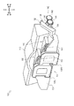
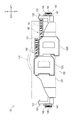
センター役物100は、本発明に係る可動演出装置の実施の一形態である。センター役物100は、液晶画面26に表示される図柄遊技に応じて可動し、遊技者に視覚的な印象(インパクト)を与えることができる。図4から図8までに示すように、センター役物100の上部は、主として基台110と、可動部130と、駆動機構140と、左固定部150と、右固定部160と、により構成される。   The center accessory 100 is an embodiment of the movable effect device according to the present invention. The center accessory 100 moves according to the symbol game displayed on the liquid crystal screen 26, and can give a visual impression (impact) to the player. As shown in FIGS. 4 to 8, the upper portion of the center accessory 100 is mainly composed of a base 110, a movable part 130, a drive mechanism 140, a left fixing part 150, and a right fixing part 160. The

なお、センター役物100の構成は概ね左右対称であるため、以下の説明では左右いずれか一方の説明及び図示を適宜省略する。
また、図中においては、説明の便宜上、基台110の図示を適宜省略し、又は想像線(二点鎖線)により示している。
In addition, since the structure of the center actor 100 is generally bilaterally symmetric, the description and illustration of either the left or right will be omitted as appropriate in the following description.
In the drawing, for convenience of explanation, illustration of the base 110 is omitted as appropriate, or is shown by an imaginary line (two-dot chain line).

図4及び図6から図8までに示す基台110は、センター役物100の上部を構成する主たる構造体である。基台110は、略直方体状に形成される。基台110の前面には、文字や図柄等の基台装飾111が施される(図11参照)。基台装飾111は透過性を有する部材によって構成される。   The base 110 shown in FIGS. 4 and 6 to 8 is a main structure constituting the upper part of the center accessory 100. The base 110 is formed in a substantially rectangular parallelepiped shape. A base decoration 111 such as letters and symbols is applied to the front surface of the base 110 (see FIG. 11). The base decoration 111 is made of a transparent member.

基台110の内部には、LED等の図示せぬ発光手段が設けられる。当該発光手段を点灯させることにより、基台装飾111を発光させることができる。   Inside the base 110, light emitting means (not shown) such as an LED is provided. The base decoration 111 can emit light by turning on the light emitting means.

図4から図8までに示す可動部130は、移動及び発光することにより、遊技者に視覚的な印象(インパクト)を与えるためのものである。可動部130は、主として表示部131と、支持部132・132と、シャフト133・133と、案内孔134・134と、左可動側装飾135Lと、右可動側装飾135Rと、により構成される。   The movable part 130 shown in FIGS. 4 to 8 is for giving a visual impression (impact) to the player by moving and emitting light. The movable part 130 is mainly composed of a display part 131, support parts 132 and 132, shafts 133 and 133, guide holes 134 and 134, a left movable side decoration 135L, and a right movable side decoration 135R.

図4から図8までに示す表示部131は、略板状の部材である。表示部131は、その板面を概ね前後方向に向け、かつ長手方向を左右方向に向けた状態で、基台110の前方に配置される。表示部131は、透過性を有する部材によって構成される。   The display 131 shown in FIGS. 4 to 8 is a substantially plate-like member. The display unit 131 is disposed in front of the base 110 in a state where the plate surface is substantially directed in the front-rear direction and the longitudinal direction is directed in the left-right direction. The display unit 131 is configured by a transparent member.

図4から図8までに示す支持部132・132は、表示部131を支持するものである。支持部132・132は、それぞれ表示部131の左右両端部から概ね後上方に向かって延設される。支持部132・132は、透過性を有する部材によって構成される。
なお、本実施形態に係る支持部132・132は、表示部131と一体的に構成されるものとするが、別部材で構成することも可能である。
The support portions 132 and 132 shown in FIGS. 4 to 8 support the display portion 131. The support portions 132 and 132 are extended substantially rearward and upward from the left and right end portions of the display portion 131, respectively. The support parts 132 and 132 are made of a permeable member.
In addition, although the support parts 132 and 132 which concern on this embodiment shall be comprised integrally with the display part 131, they can also be comprised by another member.

図4から図8までに示すシャフト133・133は、可動部130の回動軸となるものである。シャフト133・133は、その長手方向を左右方向に向けた状態で、支持部132・132の後端部にそれぞれ挿通される。当該シャフト133・133は、適宜センター役物100に支持される。   The shafts 133 and 133 shown in FIGS. 4 to 8 serve as the rotation axis of the movable unit 130. The shafts 133 and 133 are inserted into the rear end portions of the support portions 132 and 132, respectively, with the longitudinal direction thereof being directed in the left-right direction. The shafts 133 and 133 are appropriately supported by the center accessory 100.

図4、図5及び図7に示す案内孔134・134は、支持部132・132を左右方向に貫通する長孔である。案内孔134・134は、支持部132・132の下部において、当該支持部132・132の長手方向に概ね沿うようにそれぞれ形成される。   The guide holes 134 and 134 shown in FIGS. 4, 5, and 7 are long holes that penetrate the support portions 132 and 132 in the left-right direction. The guide holes 134 and 134 are formed in the lower part of the support parts 132 and 132 so as to be substantially along the longitudinal direction of the support parts 132 and 132, respectively.

図4から図6までに示す左可動側装飾135Lは、表示部131の前面の左右略中央部分からやや左方にかけて形成される装飾である。左可動側装飾135Lは、アルファベットの「D」の文字を模した装飾である。   The left movable side decoration 135 </ b> L shown in FIGS. 4 to 6 is a decoration formed from the left and right substantially central part of the front surface of the display unit 131 to the left slightly. The left movable side decoration 135L is a decoration imitating the letter “D” of the alphabet.

右可動側装飾135Rは、表示部131の前面の左右略中央部分からやや右方にかけて形成される装飾である。右可動側装飾135Rは、アルファベットの「D」の文字を模した装飾であり、左可動側装飾135Lと略同一の大きさに形成される。右可動側装飾135Rは、左可動側装飾135Lのすぐ右方であって、当該左可動側装飾135Lよりもやや低い位置(下方)に配置される。   The right movable side decoration 135 </ b> R is a decoration that is formed slightly from the left and right central portions of the front surface of the display unit 131 to the right. The right movable side decoration 135R is a decoration imitating the letter “D” of the alphabet, and is formed to be approximately the same size as the left movable side decoration 135L. The right movable side decoration 135R is disposed immediately to the right of the left movable side decoration 135L and is positioned slightly lower (downward) than the left movable side decoration 135L.

左可動側装飾135L及び右可動側装飾135Rの内部には、LED等の図示せぬ発光手段が設けられる。当該発光手段を点灯させて左可動側装飾135L及び右可動側装飾135Rの周囲を発光させることにより、当該左可動側装飾135L及び右可動側装飾135Rが発光したような演出を行うことができる。   Inside the left movable side decoration 135L and the right movable side decoration 135R, a light emitting means (not shown) such as an LED is provided. By turning on the light emitting means to emit light around the left movable side decoration 135L and the right movable side decoration 135R, it is possible to produce an effect as if the left movable side decoration 135L and the right movable side decoration 135R emit light.

上述の如く可動部130を構成することで、当該可動部130はシャフト133・133を中心として回動することが可能となり、所定の方向(本実施形態においては、上下方向)に移動可能となる。   By configuring the movable part 130 as described above, the movable part 130 can rotate around the shafts 133 and 133 and can move in a predetermined direction (in the present embodiment, the vertical direction). .

図4から図8までに示す駆動機構140は、可動部130を上下方向に往復移動(回動)させるものである。駆動機構140は、主としてモータ141と、第一駆動ギヤ142と、第一従動ギヤ143と、伝達軸144と、第二駆動ギヤ145・145と、第二従動ギヤ146・146と、伝達板147・147と、駆動突起148・148と、により構成される。   The drive mechanism 140 shown in FIGS. 4 to 8 reciprocates (rotates) the movable portion 130 in the vertical direction. The drive mechanism 140 mainly includes a motor 141, a first drive gear 142, a first driven gear 143, a transmission shaft 144, second drive gears 145 and 145, second driven gears 146 and 146, and a transmission plate 147. 147 and drive protrusions 148 and 148.

図5、図7及び図8に示すモータ141は、可動部130を往復移動させるための駆動源となるものである。モータ141は、基台110の背後に配置される。モータ141の出力軸は、当該モータ141から右方に向かって突設される。   The motor 141 shown in FIGS. 5, 7, and 8 serves as a driving source for reciprocating the movable unit 130. The motor 141 is disposed behind the base 110. The output shaft of the motor 141 projects from the motor 141 toward the right.

第一駆動ギヤ142は、モータ141の出力軸に固定され、当該出力軸を中心に回転する。   The first drive gear 142 is fixed to the output shaft of the motor 141 and rotates around the output shaft.

第一従動ギヤ143は、第一駆動ギヤ142の概ね前方から当該第一駆動ギヤ142に噛合される。   The first driven gear 143 is engaged with the first drive gear 142 from approximately the front of the first drive gear 142.

図5及び図8に示す伝達軸144は、長手方向を左右方向に向けて配置される。伝達軸144は、可動部130の左端部近傍から右端部近傍までに渡って配置される。当該伝達軸144の左右中途部には、第一従動ギヤ143が固定される。   The transmission shaft 144 shown in FIGS. 5 and 8 is arranged with the longitudinal direction directed in the left-right direction. The transmission shaft 144 is disposed from the vicinity of the left end portion of the movable portion 130 to the vicinity of the right end portion. A first driven gear 143 is fixed to the middle part of the transmission shaft 144 on the left and right sides.

図4から図8までに示す第二駆動ギヤ145・145は、伝達軸144の左右両端にそれぞれ固定される。   The second drive gears 145 and 145 shown in FIGS. 4 to 8 are fixed to the left and right ends of the transmission shaft 144, respectively.

第二従動ギヤ146・146は、第二駆動ギヤ145・145の概ね前方から当該第二駆動ギヤ145・145にそれぞれ噛合される。   The second driven gears 146 and 146 are engaged with the second drive gears 145 and 145 from approximately the front of the second drive gears 145 and 145, respectively.

伝達板147・147は、略円形板状の部材であり、その板面を左右方向に向けて配置される。当該伝達板147・147の外周の一部(上部)は概ね上方に突出するように形成される。伝達板147・147は、第二従動ギヤ146・146の内側面にそれぞれ固定される。   The transmission plates 147 and 147 are substantially circular plate-like members, and are arranged with their plate surfaces facing in the left-right direction. A part (upper part) of the outer periphery of the transmission plates 147 and 147 is formed so as to protrude substantially upward. The transmission plates 147 and 147 are fixed to the inner side surfaces of the second driven gears 146 and 146, respectively.

駆動突起148・148は、略円柱状の部材であり、伝達板147・147の突出部から内側に向かって突設され、可動部130の左右に形成された案内孔134・134にそれぞれ挿通される(図9参照)。   The drive protrusions 148 and 148 are substantially columnar members, projecting inward from the projecting portions of the transmission plates 147 and 147, and inserted through guide holes 134 and 134 formed on the left and right sides of the movable portion 130, respectively. (See FIG. 9).

図4から図8までに示す左固定部150は、遊技者に視覚的な印象(インパクト)を与えるためのものである。
左固定部150は、略箱状の部材により構成される。左固定部150の背面(後面)は、上下方向及び左右方向に平行な平面に形成され、左固定部150の前面は、左から右に向かうにつれて前方に延出するような曲面に形成される。
左固定部150の上下方向幅(高さ)は、左可動側装飾135Lの上下方向幅よりも小さくなるように形成される。より詳細には、左固定部150の上下方向幅は、左可動側装飾135Lと右可動側装飾135Rとの高さの差と略同一幅となるように形成される。
左固定部150は、その左端部近傍が表示部131(より詳細には、左可動側装飾135L)の背後に位置するようにして当該左可動側装飾135Lの右上方に配置される。当該左固定部150は、適宜基台110の前面に固定される。
The left fixing portion 150 shown in FIGS. 4 to 8 is for giving a visual impression (impact) to the player.
The left fixing part 150 is configured by a substantially box-shaped member. The back surface (rear surface) of the left fixed portion 150 is formed in a plane parallel to the up and down direction and the left and right direction, and the front surface of the left fixed portion 150 is formed in a curved surface that extends forward from left to right. .
The vertical width (height) of the left fixed portion 150 is formed to be smaller than the vertical width of the left movable side decoration 135L. More specifically, the vertical width of the left fixed portion 150 is formed to be substantially the same width as the height difference between the left movable side decoration 135L and the right movable side decoration 135R.
The left fixed portion 150 is disposed on the upper right side of the left movable side decoration 135L such that the vicinity of the left end thereof is located behind the display portion 131 (more specifically, the left movable side decoration 135L). The left fixing part 150 is appropriately fixed to the front surface of the base 110.

左固定部150の前面には、左固定側装飾151が施される。左固定側装飾151は、アルファベットの「DYNAMITE」の文字を模した装飾であり、当該文字が左固定部150の前面の左端部から右端部に渡って形成される(図11参照)。左固定側装飾151の「DYNAMITE」の各文字の大きさは、左可動側装飾135Lの「D」の文字の大きさよりも小さくなるように形成される。左固定側装飾151の文字のうち、最も左側に位置する「D」の文字は、左可動側装飾135Lの背後に位置するように形成される。   A left fixed side decoration 151 is applied to the front surface of the left fixed portion 150. The left fixed decoration 151 is a decoration imitating the letters “DYNAMITE” of the alphabet, and the letters are formed from the left end to the right end of the front surface of the left fixed portion 150 (see FIG. 11). The size of each character of “DYNAMITE” of the left fixed side decoration 151 is formed to be smaller than the size of the character “D” of the left movable side decoration 135L. Among the characters of the left fixed side decoration 151, the character “D” located on the leftmost side is formed so as to be located behind the left movable side decoration 135L.

図4から図8までに示す右固定部160は、遊技者に視覚的な印象(インパクト)を与えるためのものである。
右固定部160は、左固定部150と略同一形状となるように形成される。
右固定部160は、その左端部近傍が表示部131(より詳細には、右可動側装飾135R)の背後に位置するようにして当該右可動側装飾135Rの右上方に配置される。当該右固定部160は、適宜基台110の前面に固定される。
The right fixing portion 160 shown in FIGS. 4 to 8 is for giving a visual impression (impact) to the player.
The right fixing part 160 is formed to have substantially the same shape as the left fixing part 150.
The right fixed portion 160 is arranged on the upper right side of the right movable side ornament 135R so that the vicinity of the left end portion is located behind the display portion 131 (more specifically, the right movable side ornament 135R). The right fixing portion 160 is fixed to the front surface of the base 110 as appropriate.

右固定部160の前面には、右固定側装飾161が施される。右固定側装飾161は、アルファベットの「DYNAMITE」の文字を模した装飾であり、当該文字が右固定部160の前面の左端部から右端部に渡って形成される(図11参照)。右固定側装飾161の「DYNAMITE」の各文字の大きさは、右可動側装飾135Rの「D」の文字の大きさよりも小さくなるように形成される。右固定側装飾161の文字のうち、最も左側に位置する「D」の文字は、右可動側装飾135Rの背後に位置するように形成される。   A right fixed side decoration 161 is applied to the front surface of the right fixed portion 160. The right fixed side decoration 161 is a decoration imitating the letters “DYNAMITE” of the alphabet, and the characters are formed from the left end portion to the right end portion of the front surface of the right fixed portion 160 (see FIG. 11). The size of each character of “DYNAMITE” of the right fixed side decoration 161 is formed to be smaller than the size of the letter “D” of the right movable side decoration 135R. Of the characters of the right fixed decoration 161, the character “D” located on the leftmost side is formed so as to be positioned behind the right movable decoration 135R.

以下では、上述の如く構成されたセンター役物100の複数の状態及び状態遷移の様子について説明する。   Hereinafter, a plurality of states and state transitions of the center accessory 100 configured as described above will be described.

まず、上述した図4から図8までに示す状態においては、可動部130が基台110の基台装飾111(図11参照)と前方から重複する状態で、すなわち可動部130が基台装飾111を前方から隠蔽する状態で、当該可動部130を基台110の前方に位置させている。この状態のことを、以下では「第一状態」と記す。   First, in the state shown in FIGS. 4 to 8 described above, the movable part 130 overlaps the base decoration 111 (see FIG. 11) of the base 110 from the front, that is, the movable part 130 is the base decoration 111. The movable part 130 is positioned in front of the base 110 in a state of concealing from the front. Hereinafter, this state is referred to as a “first state”.

第一状態においては、可動部130は、左固定部150の左固定側装飾151の一部と前方から重複する位置にある。
より詳細には、可動部130に形成された左可動側装飾135Lによって左固定部150の左端部近傍が前方から隠蔽され、当該左固定部150に形成された左固定側装飾151のうち、「D」の文字部分が前方(遊技者側)から視認不能となる。すなわち、左固定側装飾151のうち「D」の文字部分は、同じ種類(同じ「D」の文字)であって当該左固定側装飾151の「D」の文字よりも大きい左可動側装飾135Lによって隠蔽されることになる。
この状態においては、左可動側装飾135Lの「D」の文字部分と、左固定側装飾151のうち左可動側装飾135Lにより隠蔽されていない「YNAMITE」の文字部分と、によって、「DYNAMITE」という1つのキャラクタ(第一のキャラクタ)を構成する(図6参照)。
In the first state, the movable portion 130 is in a position overlapping with a part of the left fixed side decoration 151 of the left fixed portion 150 from the front.
More specifically, the left movable portion decoration 135L formed on the movable portion 130 conceals the vicinity of the left end portion of the left fixed portion 150 from the front, and among the left fixed side ornament 151 formed on the left fixed portion 150, “ The character portion of “D” becomes invisible from the front (player side). That is, the character portion “D” of the left fixed side decoration 151 is of the same type (the same “D” character) and is larger than the character “D” of the left fixed side decoration 151, the left movable side decoration 135 </ b> L. Will be concealed.
In this state, the character part “D” of the left movable side decoration 135L and the character part “YNAMITE” that is not concealed by the left movable side decoration 135L in the left fixed side decoration 151 are referred to as “DYNAMITE”. One character (first character) is formed (see FIG. 6).

ここで、「キャラクタ」とは、性格や人格等、小説や映画等の登場人物、文字や記号等を広く意味するものである。   Here, the “character” broadly means characters such as personality and personality, characters such as novels and movies, characters and symbols.

前記第一のキャラクタは、「DYNAMITE」の文字のうち「D」の文字のみが大きく構成されることになり、「DYNAMITE」という英単語の意味の印象とともに、遊技者に力強い印象を与えることができる。   In the first character, only the letter “D” among the letters “DYNAMITE” is configured to be large, and the player can make a strong impression with the impression of the meaning of the English word “DYNAMITE”. it can.

また、同様に、第一状態においては、可動部130は、右固定部160の右固定側装飾161の一部と前方から重複する位置にある。
より詳細には、可動部130に形成された右可動側装飾135Rによって右固定部160の左端部近傍が前方から隠蔽され、当該右固定部160に形成された右固定側装飾161のうち、「D」の文字部分が前方(遊技者側)から視認不能となる。すなわち、右固定側装飾161のうち「D」の文字部分は、同じ種類(同じ「D」の文字)であって当該右固定側装飾161の「D」の文字よりも大きい右可動側装飾135Rによって隠蔽されることになる。
この状態においては、右可動側装飾135Rの「D」の文字部分と、右固定側装飾161のうち右可動側装飾135Rにより隠蔽されていない「YNAMITE」の文字部分と、によって、「DYNAMITE」という1つのキャラクタ(第一のキャラクタ)を構成する(図6参照)。この状態(第一状態)における可動部130と左固定部150及び右固定部160との相対的な位置関係のことを、以下では「第一の相対位置」と記す。
Similarly, in the first state, the movable portion 130 is in a position overlapping with a part of the right fixed side decoration 161 of the right fixed portion 160 from the front.
More specifically, the vicinity of the left end portion of the right fixed portion 160 is concealed from the front by the right movable side decoration 135R formed on the movable portion 130, and among the right fixed side decoration 161 formed on the right fixed portion 160, “ The character portion of “D” becomes invisible from the front (player side). That is, the character portion “D” of the right fixed side decoration 161 is of the same type (the same “D” character) and is larger than the character “D” of the right fixed side decoration 161. Will be concealed.
In this state, the character portion “D” of the right movable side decoration 135R and the character portion “YNAMITE” of the right fixed side decoration 161 that is not concealed by the right movable side decoration 135R are referred to as “DYNAMITE”. One character (first character) is formed (see FIG. 6). Hereinafter, the relative positional relationship between the movable part 130 and the left fixed part 150 and the right fixed part 160 in this state (first state) will be referred to as a “first relative position”.

第一状態においては、左固定部150が左可動側装飾135Lの背後から右に向かうにつれて前方(遊技者側)へと延出している(図4等参照)。このように左固定部150を立体的に構成することにより、当該左固定部150の左固定側装飾151と左可動側装飾135Lとの一体感を出すことができる。
同様に、第一状態においては、右固定部160が右可動側装飾135Rの背後から右に向かうにつれて前方(遊技者側)へと延出している。このように右固定部160を立体的に構成することにより、当該右固定部160の右固定側装飾161と右可動側装飾135Rとの一体感を出すことができる。
In the first state, the left fixed portion 150 extends forward (player side) from the back of the left movable side decoration 135L toward the right (see FIG. 4 and the like). By thus configuring the left fixed portion 150 in a three-dimensional manner, a sense of unity between the left fixed side decoration 151 and the left movable side decoration 135L of the left fixed portion 150 can be obtained.
Similarly, in the first state, the right fixing portion 160 extends forward (player side) from the back of the right movable side decoration 135R toward the right. By thus configuring the right fixed portion 160 in a three-dimensional manner, a sense of unity between the right fixed side decoration 161 and the right movable side decoration 135R of the right fixed portion 160 can be obtained.

さらに、第一状態においては、左可動側装飾135L及び右可動側装飾135Rの内部に配置された発光手段が点灯される。当該発光手段が点灯されることによって、当該左可動側装飾135L及び右可動側装飾135Rが発光し、遊技者に当該左可動側装飾135L及び右可動側装飾135Rによる印象を強く与えることができる。   Further, in the first state, the light emitting means arranged in the left movable side decoration 135L and the right movable side decoration 135R are turned on. When the light emitting means is turned on, the left movable side decoration 135L and the right movable side decoration 135R emit light, and the player can be given a strong impression of the left movable side decoration 135L and the right movable side decoration 135R.

第一状態から、モータ141を一方向に回転駆動させ、第一駆動ギヤ142を側面(図7)視反時計回りに回転させると、当該第一駆動ギヤ142と噛合した第一従動ギヤ143、伝達軸144及び第二駆動ギヤ145・145は側面視時計回りに回転する。第二駆動ギヤ145・145が側面視時計回りに回転すると、当該第二駆動ギヤ145・145と噛合した第二従動ギヤ146・146及び伝達板147・147は側面視反時計回りに回転する。   From the first state, when the motor 141 is rotationally driven in one direction and the first drive gear 142 is rotated counterclockwise as viewed from the side (FIG. 7), the first driven gear 143 meshed with the first drive gear 142, The transmission shaft 144 and the second drive gears 145 and 145 rotate clockwise in a side view. When the second drive gears 145 and 145 rotate clockwise in side view, the second driven gears 146 and 146 and the transmission plates 147 and 147 engaged with the second drive gears 145 and 145 rotate counterclockwise in side view.

伝達板147・147と共に、当該伝達板147・147に固定された駆動突起148・148も側面視反時計回りに回転する(図9の(a)から(c)まで参照)。当該駆動突起148・148は可動部130の案内孔134・134を押しながら回転するため、当該駆動突起148・148の回転に伴って、可動部130もシャフト133・133を中心として側面視反時計回りに回転し、正面視においては下方に移動することになる(図11参照)。   Along with the transmission plates 147 and 147, the drive projections 148 and 148 fixed to the transmission plates 147 and 147 also rotate counterclockwise when viewed from the side (see FIGS. 9A to 9C). Since the drive protrusions 148 and 148 rotate while pushing the guide holes 134 and 134 of the movable portion 130, the movable portion 130 also rotates counterclockwise around the shafts 133 and 133 as the drive protrusions 148 and 148 rotate. It rotates around and moves downward in front view (see FIG. 11).

可動部130の支持部132・132の長手方向が概ね上下方向を向いたとき(図9(c)及び図10参照)に、モータ141の駆動が停止される。   When the longitudinal direction of the support portions 132 and 132 of the movable portion 130 is substantially in the vertical direction (see FIGS. 9C and 10), the driving of the motor 141 is stopped.

図11に示すように、この状態においては、基台110の基台装飾111が露出し、前方(遊技者側)から当該基台装飾111が視認可能となる。この状態のことを、以下では「第二状態」と記す。   As shown in FIG. 11, in this state, the base decoration 111 of the base 110 is exposed, and the base decoration 111 is visible from the front (player side). Hereinafter, this state is referred to as a “second state”.

第二状態においては、可動部130は、左固定部150の左固定側装飾151と前方から重複しない位置にある。
この状態においては、左固定側装飾151自身の文字部分のみによって、「DYNAMITE」という第一のキャラクタとは異なる1つのキャラクタ(第二のキャラクタ)を構成する(図11参照)。
In the second state, the movable part 130 is in a position that does not overlap with the left fixed side decoration 151 of the left fixed part 150 from the front.
In this state, only the character portion of the left fixed decoration 151 itself constitutes one character (second character) different from the first character “DYNAMITE” (see FIG. 11).

前記第二のキャラクタは、「DYNAMITE」の文字が全て同じ大きさで構成されるため、第一のキャラクタに比べて全体として小さくなり、遊技者にすっきりとした印象を与えることができるとともに、遊技者の注意を当該第二のキャラクタだけでなく基台110の基台装飾111にも向けることができる。   In the second character, since the letters “DYNAMITE” are all the same size, the second character is smaller as a whole than the first character, and can give a clear impression to the player. The user's attention can be directed not only to the second character but also to the base decoration 111 of the base 110.

また、同様に、第一状態においては、可動部130は、右固定部160の右固定側装飾161と前方から重複しない位置にある。
この状態においては、右固定側装飾161自身の文字部分のみによって、「DYNAMITE」という第一のキャラクタとは異なる1つのキャラクタ(第二のキャラクタ)を構成する(図11参照)。この状態(第二状態)における可動部130と左固定部150及び右固定部160との相対的な位置関係のことを、以下では「第二の相対位置」と記す。
Similarly, in the first state, the movable portion 130 is in a position that does not overlap with the right fixed side decoration 161 of the right fixed portion 160 from the front.
In this state, only the character portion of the right fixed decoration 161 itself constitutes one character (second character) different from the first character “DYNAMITE” (see FIG. 11). The relative positional relationship between the movable part 130 and the left fixed part 150 and the right fixed part 160 in this state (second state) is hereinafter referred to as “second relative position”.

さらに、第二状態においては、前方(遊技者側)から基台110の基台装飾111が視認可能となり、当該基台装飾111によって前記第一のキャラクタ及び第二のキャラクタとは異なる第三のキャラクタが構成される。
また、第二状態においては、基台110の内部に配置された発光手段が点灯される。当該発光手段が点灯されることによって、基台装飾111が発光し、遊技者に当該基台装飾111(すなわち、第三のキャラクタ)による印象を強く与えることができる。
Further, in the second state, the base decoration 111 of the base 110 can be visually recognized from the front (player side), and the third decoration different from the first character and the second character by the base decoration 111. A character is composed.
In the second state, the light emitting means disposed inside the base 110 is turned on. When the light emitting means is turned on, the base decoration 111 emits light, and the player can be given a strong impression of the base decoration 111 (that is, the third character).

さらに、第二状態においては、可動部130は、シャフト133・133を中心に下方に回動しているため、当該可動部130は前傾している。このため、遊技者からは左可動側装飾135L及び右可動側装飾135Rの内容が識別し難くなるため、遊技者の注意が当該左可動側装飾135L及び右可動側装飾135Rではなく、基台装飾111、左固定側装飾151及び右固定側装飾161に行き易くなる。   Furthermore, in the second state, the movable part 130 is pivoted downward about the shafts 133 and 133, so the movable part 130 is tilted forward. For this reason, it becomes difficult for the player to identify the contents of the left movable side decoration 135L and the right movable side decoration 135R, so the player's attention is not the left movable side decoration 135L and the right movable side decoration 135R but the base decoration. 111, the left fixed side decoration 151 and the right fixed side decoration 161 are easily accessible.

上記とは逆に第二状態から第一状態へと状態遷移させる場合、モータ141を上記と逆方向に回転駆動させる。これによって、上記とは逆に可動部130は側面(図7)視時計回りに回転し、正面視においては上方に移動することになる(図6参照)。このようにして、再び第一状態に状態遷移することができる。   In contrast to the above, when the state transition is made from the second state to the first state, the motor 141 is rotationally driven in the opposite direction to the above. As a result, contrary to the above, the movable portion 130 rotates clockwise as viewed from the side (FIG. 7) and moves upward in the front view (see FIG. 6). In this way, the state transition can be made again to the first state.

このように、可動部130は、上下方向(所定の方向)に移動することで、左固定側装飾151及び右固定側装飾161の一部と重複する位置と、左固定側装飾151及び右固定側装飾161と重複しない位置と、に位置することができる。   As described above, the movable unit 130 moves in the vertical direction (predetermined direction), so that it overlaps with a part of the left fixed side decoration 151 and the right fixed side decoration 161, and the left fixed side decoration 151 and the right fixed side. It can be located at a position that does not overlap with the side decoration 161.

以上の如く、本実施形態に係る遊技機1のセンター役物100は、
前方から視認可能な位置に左固定側装飾151及び右固定側装飾161(固定側装飾)が施された左固定部150及び右固定部160(固定部)と、
前方から視認可能な位置に左可動側装飾135L及び右可動側装飾135R(可動側装飾)が施され、左固定部150及び右固定部160の前方にて上下方向(所定の方向)に移動自在となる可動部130と、
を備え、
可動部130が左固定部150及び右固定部160に対して前後に重複する第一の相対位置にある場合、当該可動部130の左可動側装飾135L及び右可動側装飾135R並びに当該左固定部150及び右固定部160の左固定側装飾151及び右固定側装飾161によって第一のキャラクタを構成し、
可動部130が前記第一の相対位置から移動した第二の相対位置にある場合、当該左固定側装飾151及び右固定側装飾161によって前記第一のキャラクタとは異なる第二のキャラクタを構成するものである。
As described above, the center accessory 100 of the gaming machine 1 according to the present embodiment is
A left fixed part 150 and a right fixed part 160 (fixed part) provided with a left fixed side decoration 151 and a right fixed side decoration 161 (fixed side decoration) at a position visible from the front;
A left movable side decoration 135L and a right movable side decoration 135R (movable side decoration) are provided at a position visible from the front, and can be moved in the vertical direction (predetermined direction) in front of the left fixed portion 150 and the right fixed portion 160. A movable part 130,
With
When the movable part 130 is in the first relative position that overlaps with the left fixed part 150 and the right fixed part 160 in the front-rear direction, the left movable side decoration 135L and the right movable side decoration 135R of the movable part 130 and the left fixed part 150 and the left fixed side decoration 151 and the right fixed side decoration 161 of the right fixed part 160 constitute a first character,
When the movable unit 130 is at the second relative position moved from the first relative position, the left fixed side decoration 151 and the right fixed side decoration 161 form a second character different from the first character. Is.

このように構成することにより、遊技者に可動部130の動きとともにキャラクタの変化を視認させることで、新鮮な印象を与えることができる。
すなわち、第一状態と第二状態との間で状態遷移することにより、遊技者に可動部130の動きを視認させるだけでなく、当該可動部130が構成していた第一のキャラクタが第二のキャラクタへと変化する様子や、第二のキャラクタが上昇してきた可動部130によって第一のキャラクタへと変化する様子を視認させることができる。これによって、遊技者に様々な印象を与えることができる。
By comprising in this way, a fresh impression can be given by making a player visually recognize the change of a character with the movement of the movable part 130. FIG.
That is, by making a state transition between the first state and the second state, not only does the player visually recognize the movement of the movable part 130, but the first character that the movable part 130 has configured is the second character. It is possible to visually recognize the state of changing to the first character and the state of changing to the first character by the movable part 130 where the second character has risen. Thereby, various impressions can be given to the player.

また、本実施形態に係る遊技機1のセンター役物100は、
第一状態においては、
可動部130が基台110の基台装飾111を前方から隠蔽し、
当該可動部130の左可動側装飾135Lと、左固定部150の左固定側装飾151であって当該可動部130によって隠蔽される部分と、は同じ種類のもの(「D」の文字)であって、その大きさは左固定側装飾151の方が小さく、
また当該可動部130の右可動側装飾135Rと、右固定部160の右固定側装飾161であって当該可動部130によって隠蔽される部分と、は同じ種類のもの(「D」の文字)であって、その大きさは右固定側装飾161の方が小さく、
第二状態においては、
可動部130が移動することにより左固定部150の左固定側装飾151及び右固定部160の右固定側装飾161によって第一のキャラクタよりも大きさが小さく変更された第二のキャラクタが表示されるとともに、基台110の基台装飾111による第三のキャラクタが表示されるものである。
In addition, the center accessory 100 of the gaming machine 1 according to the present embodiment is
In the first state,
The movable part 130 conceals the base decoration 111 of the base 110 from the front,
The left movable side decoration 135L of the movable part 130 and the left fixed side decoration 151 of the left fixed part 150 that are concealed by the movable part 130 are of the same type (letter “D”). The size of the left fixed side decoration 151 is smaller,
Also, the right movable side decoration 135R of the movable part 130 and the right fixed side decoration 161 of the right fixed part 160 that are concealed by the movable part 130 are of the same type (letter “D”). The size of the right fixed side decoration 161 is smaller,
In the second state,
As the movable part 130 moves, the second character whose size is changed smaller than the first character by the left fixed side decoration 151 of the left fixed part 150 and the right fixed side decoration 161 of the right fixed part 160 is displayed. In addition, a third character by the base decoration 111 of the base 110 is displayed.

このように構成することにより、第一状態においては左可動側装飾135L及び左固定側装飾151並びに右可動側装飾135R及び右固定側装飾161によってそれぞれ第一のキャラクタを構成し、第二状態(可動部130を左固定側装飾151及び右固定側装飾161を隠蔽しない位置に移動させた場合)においては左固定側装飾151及び右固定側装飾161によって第一のキャラクタよりも大きさが小さい第二のキャラクタを表示することで、空きスペースを確保し、当該空いたスペースに新たなキャラクタとして基台装飾111による第三のキャラクタが登場したように遊技者に見せることができる。
すなわち、第一状態においては第一のキャラクタのみを表示していた領域に、第二状態においては第一のキャラクタと同じ種類(すなわち、同じ「DYNAMITE」という意味)の第二のキャラクタを、第一のキャラクタに比べて小さく表示するとともに、新たな第三のキャラクタを表示させることができる。
With this configuration, in the first state, the left movable side decoration 135L and the left fixed side decoration 151, the right movable side decoration 135R, and the right fixed side decoration 161 constitute the first character, respectively, and the second state ( In the case where the movable part 130 is moved to a position where the left fixed side decoration 151 and the right fixed side decoration 161 are not concealed), the left fixed side decoration 151 and the right fixed side decoration 161 are smaller in size than the first character. By displaying the second character, an empty space can be secured and the player can be shown as if the third character by the base decoration 111 appeared as a new character in the empty space.
That is, in the area where only the first character is displayed in the first state, the second character of the same type as the first character (that is, the same meaning of “DYNAMITE”) is displayed in the second state. A new third character can be displayed while being displayed smaller than one character.

なお、本実施形態においては、第一のキャラクタ及び第二のキャラクタは「DYNAMITE」の英単語を構成するものとしたが、本発明はこれに限るものではなく、第一のキャラクタ及び第二のキャラクタは、それぞれが一体として一つの意味や纏まりを成すようなキャラクタであれば良い。
例えば、左固定側装飾151として横たわった人物の絵を施し、当該人物の顔の部分を左可動側装飾135Lで隠蔽可能とし、当該左可動側装飾135Lには左固定側装飾151の人物とは異なる表情の顔の部分を施すことも可能である。このように構成した場合、第一状態と第二状態とで人物の表情が変化する様子を遊技者に視認させることができる。
また、本実施形態においては、第一のキャラクタと第二のキャラクタとで英単語の意味は同じであるが、異なる単語に変化させる構成とすることも可能である。
In the present embodiment, the first character and the second character constitute an English word “DYNAMITE”, but the present invention is not limited to this, and the first character and the second character The characters may be characters that each form a single meaning or group.
For example, a picture of a person lying down as the left fixed side decoration 151 is applied, and the face portion of the person can be concealed by the left movable side decoration 135L, and the left movable side decoration 135L includes the person of the left fixed side decoration 151. It is also possible to apply facial parts with different facial expressions. When comprised in this way, a player can be made to visually recognize a mode that a person's facial expression changes with a 1st state and a 2nd state.
In the present embodiment, the meaning of the English word is the same between the first character and the second character, but it may be changed to a different word.

また、本実施形態においては、第一のキャラクタ及び第二のキャラクタはいずれも「DYNAMITE」の英単語を構成しているが、「D」の文字部分の大きさが異なるため、互いに異なるキャラクタを構成している。すなわち、第一のキャラクタ及び第二のキャラクタは、(1)同じ形であっても大きさが(一部でも)異なっていれば異なるキャラクタを構成し、(2)同じ大きさであっても形が異なっていれば異なるキャラクタを構成し、(3)同じ大きさで同じ形であっても、色が異なっていれば異なるキャラクタを構成する。   In the present embodiment, both the first character and the second character constitute the English word “DYNAMITE”. However, since the size of the character portion “D” is different, different characters are used. It is composed. That is, the first character and the second character are (1) even if they are the same shape, but they are different if they are different in size (partially), and (2) they are the same size If the shapes are different, different characters are formed. (3) Even if they are the same size and the same shape, different characters are formed if the colors are different.

また、本実施形態においては、図12(a)に示すように、左固定部150の前面は、左から右に向かうにつれて前方に延出するような曲面に形成されるものとしたが、本発明はこれに限るものではない。すなわち、図12(b)に示すように、左固定部150の前面は、左から右に向かうにつれて段階的に前方に演出するような階段状に形成される構成とすることも可能である。右固定部160についても同様である。   In the present embodiment, as shown in FIG. 12A, the front surface of the left fixed portion 150 is formed in a curved surface that extends forward from left to right. The invention is not limited to this. That is, as shown in FIG. 12 (b), the front surface of the left fixed portion 150 may be formed in a staircase shape that produces a forward effect stepwise from left to right. The same applies to the right fixing portion 160.

また、左固定部150に左固定側装飾151(例えば、文字Rの列)を施す場合、図13(b)に示すように、図13(a)におけるA−A矢視において全ての文字R・R・・・を同じ大きさで、かつ等間隔に配列すると、前方(遊技者側)から当該左固定側装飾151を見た場合(図13(a)におけるB−B矢視)、右に向かうにつれて文字Rの横幅が狭く、かつ隣り合う文字R・Rの間隔が狭く歪んで見える。
そこで、図13(c)に示すように、前述の歪みを予め考慮して、図13(a)におけるA−A矢視において右に向かうにつれて文字Rの横幅を広く、かつ隣り合う文字R・Rの間隔が広くなるように文字R・R・・・を配列することで、前方(遊技者側)から当該左固定側装飾151を見た場合(図13(a)におけるB−B矢視)に全ての文字R・R・・・が同じ大きさで、かつ等間隔に見えるようにすることができる。これは、文字の列に限らず図形等でも同様であり、また右固定部160についても同様である。
Further, when the left fixed side decoration 151 (for example, a row of characters R) is applied to the left fixed portion 150, as shown in FIG. 13B, all the characters R are viewed in the direction of arrows AA in FIG. -When R ... is the same size and arranged at equal intervals, when the left fixed side decoration 151 is viewed from the front (player side) (as viewed from arrow BB in FIG. 13 (a)), the right The width of the character R becomes narrower and the distance between the adjacent characters R · R appears narrower and distorted as it goes to.
Therefore, as shown in FIG. 13 (c), the above-described distortion is taken into consideration in advance, and the width of the character R becomes wider toward the right in the direction of arrow AA in FIG. When the left fixed side decoration 151 is viewed from the front (player side) by arranging the characters R, R,... So that the interval of R is wide (viewed by arrows BB in FIG. 13A) ) All the characters R, R... Can be seen at the same size and at equal intervals. This applies not only to character strings but also to graphics and the like, and also to the right fixing unit 160.

また、本実施形態においては、可動部130を上下方向に移動させることで、第一状態と第二状態とを切り替え、遊技者に第一のキャラクタ又は第二のキャラクタを視認させるものとしたが、さらに別の可動部を設け、3つ以上のキャラクタを切り替えながら視認させる構成とすることも可能である。   In the present embodiment, the movable portion 130 is moved in the vertical direction to switch between the first state and the second state, so that the player can visually recognize the first character or the second character. Furthermore, it is possible to provide another movable part so that three or more characters can be viewed while switching.

また、本実施形態においては、第一状態において可動部130の左可動側装飾135Lによって左固定部150の左固定側装飾151を隠蔽し、当該左可動側装飾135Lと左固定側装飾151のうち左可動側装飾135Lにより隠蔽されていない部分とによって第一のキャラクタを構成するものとしたが、可動部130の左可動側装飾135Lを半透明の(透光性を有する)部材で構成し、当該左可動側装飾135Lと左固定側装飾151(左可動側装飾135Lと重複する部分を含む)とによって第一のキャラクタを構成するものとしても良い。すなわち、この場合、左可動側装飾135Lを透して視認される左固定側装飾151も含めて第一のキャラクタを構成する。
これは、可動部130の右可動側装飾135Rと右固定部160の右固定側装飾161についても同様である。
In the present embodiment, the left fixed side decoration 151 of the left fixed part 150 is concealed by the left movable side decoration 135L of the movable part 130 in the first state, and the left movable side decoration 135L and the left fixed side decoration 151 are The first character is configured by the portion that is not concealed by the left movable side decoration 135L, but the left movable side decoration 135L of the movable unit 130 is configured by a translucent member (having translucency), The left movable side decoration 135L and the left fixed side decoration 151 (including a portion overlapping the left movable side decoration 135L) may be used as the first character. That is, in this case, the first character is configured including the left fixed side decoration 151 that is visible through the left movable side decoration 135L.
The same applies to the right movable side decoration 135R of the movable part 130 and the right fixed side decoration 161 of the right fixed part 160.

また、本実施形態においては、図14に模式的に示すように、可動部130(図14(a)参照)が左固定部150(図14(a)参照)の左固定側装飾151の一部(「CBC」の文字列のうち、左側の「C」の文字部分)と前方から重複する位置に移動した場合(図14(b)参照)、当該可動部130の左可動側装飾135L及び当該左固定側装飾151によって第一のキャラクタ(「ABC」の文字列)を構成し、可動部130が左固定部150の左固定側装飾151と前方から重複しない位置に移動した場合(図14(c)参照)、当該左固定側装飾151のみによって第一のキャラクタとは異なる第二のキャラクタ(「CBC」の文字列)を構成するものとした。
しかし、本発明はこれに限るものではなく、例えば、可動部130が左固定部150の左固定側装飾151の他の部分(「CBC」の文字列のうち、右側の「C」の文字部分)と前方から重複する位置に移動した場合(図14(d)参照)、当該可動部130の左可動側装飾135L及び当該左固定側装飾151によって第一のキャラクタとは異なる第二のキャラクタ(「CBA」の文字列)を構成するものとしても良い。
また、可動部130が左固定部150の左固定側装飾151と前方から重複しない位置に移動した場合(図14(e)参照)、当該可動部130の左可動側装飾135L及び当該左固定側装飾151によって第一のキャラクタとは異なる第二のキャラクタ(「CBCA」の文字列)を構成するものとしても良い。
これは、可動部130の右可動側装飾135Rと右固定部160の右固定側装飾161についても同様である。
In the present embodiment, as schematically shown in FIG. 14, the movable portion 130 (see FIG. 14A) is one of the left fixed side decorations 151 of the left fixed portion 150 (see FIG. 14A). Part (refer to FIG. 14 (b)), the left movable side decoration 135L of the movable part 130 and the movable part 130 are moved to the position overlapping the front part (the character part "C" on the left side of the character string "CBC") from the front. When the left fixed side decoration 151 forms a first character (a character string “ABC”), and the movable part 130 moves from the front to a position that does not overlap with the left fixed side decoration 151 of the left fixed part 150 (FIG. 14). (See (c)), only the left fixed side decoration 151 constitutes a second character (a character string “CBC”) different from the first character.
However, the present invention is not limited to this. For example, the movable portion 130 is another portion of the left fixed side decoration 151 of the left fixed portion 150 (the character portion “C” on the right side of the character string “CBC”). ) And an overlapping position from the front (see FIG. 14D), a second character (different from the first character by the left movable side decoration 135L and the left fixed side decoration 151 of the movable part 130) A character string “CBA”) may be configured.
Further, when the movable unit 130 moves from the front to the left fixed side decoration 151 of the left fixed unit 150 (see FIG. 14E), the left movable side decoration 135L of the movable unit 130 and the left fixed side The decoration 151 may constitute a second character (a character string “CBCA”) different from the first character.
The same applies to the right movable side decoration 135R of the movable part 130 and the right fixed side decoration 161 of the right fixed part 160.

1:遊技機,100:センター役物,110:基台,130:可動部,135L:左可動側装飾,135R:右可動側装飾,140:駆動機構,150:左固定部,151:左固定側装飾,160:右固定部,161:右固定側装飾   1: gaming machine, 100: center role, 110: base, 130: movable part, 135L: left movable side decoration, 135R: right movable side decoration, 140: drive mechanism, 150: left fixed part, 151: left fixed Side decoration, 160: Right fixed part, 161: Right fixed side decoration

Claims (1)

前方から視認可能な位置に固定側装飾が施された固定部と、
前方から視認可能な位置に可動側装飾が施され、前記固定部の前方にて所定の方向に移動自在となる可動部と、
を備え、
前記可動部が前記固定部に対して前後に重複する第一の相対位置にある場合、当該可動部の可動側装飾及び当該固定部の固定側装飾によって第一のキャラクタを構成し、
前記可動部が前記第一の相対位置から移動した第二の相対位置にある場合、当該可動部の可動側装飾及び前記固定部の固定側装飾、又は当該固定部の固定側装飾のみによって前記第一のキャラクタとは異なる第二のキャラクタを構成する、
遊技機の可動演出装置。
A fixed part with a fixed side decoration at a position visible from the front;
A movable part is provided with a movable decoration at a position visible from the front, and is movable in a predetermined direction in front of the fixed part; and
With
When the movable part is at a first relative position that overlaps the front and rear with respect to the fixed part, the first character is configured by the movable side decoration of the movable part and the fixed side decoration of the fixed part,
When the movable part is in the second relative position moved from the first relative position, the movable side decoration of the movable part and the fixed side decoration of the fixed part, or the fixed side decoration of the fixed part only. Constituting a second character different from the one character,
A movable production device for gaming machines.
JP2011118527A 2011-05-26 2011-05-26 Movable direction device for gaming machine Expired - Fee Related JP5477337B2 (en)

Priority Applications (1)

Application Number Priority Date Filing Date Title
JP2011118527A JP5477337B2 (en) 2011-05-26 2011-05-26 Movable direction device for gaming machine

Applications Claiming Priority (1)

Application Number Priority Date Filing Date Title
JP2011118527A JP5477337B2 (en) 2011-05-26 2011-05-26 Movable direction device for gaming machine

Publications (2)

Publication Number Publication Date
JP2012245122A true JP2012245122A (en) 2012-12-13
JP5477337B2 JP5477337B2 (en) 2014-04-23

Family

ID=47466161

Family Applications (1)

Application Number Title Priority Date Filing Date
JP2011118527A Expired - Fee Related JP5477337B2 (en) 2011-05-26 2011-05-26 Movable direction device for gaming machine

Country Status (1)

Country Link
JP (1) JP5477337B2 (en)

Cited By (2)

* Cited by examiner, † Cited by third party
Publication number Priority date Publication date Assignee Title
JP2015043818A (en) * 2013-08-27 2015-03-12 株式会社サンセイアールアンドディ Game machine
JP2016083507A (en) * 2016-02-02 2016-05-19 株式会社藤商事 Pinball game machine

Citations (2)

* Cited by examiner, † Cited by third party
Publication number Priority date Publication date Assignee Title
JPH07151870A (en) * 1993-09-16 1995-06-16 Eta Sa Fab Ebauches Analog-display type timer, which can provide alphanumeric information regarding operating mode or state of programmed phenomenon
JP2010142276A (en) * 2008-12-16 2010-07-01 Kyoraku Sangyo Kk Game machine

Patent Citations (2)

* Cited by examiner, † Cited by third party
Publication number Priority date Publication date Assignee Title
JPH07151870A (en) * 1993-09-16 1995-06-16 Eta Sa Fab Ebauches Analog-display type timer, which can provide alphanumeric information regarding operating mode or state of programmed phenomenon
JP2010142276A (en) * 2008-12-16 2010-07-01 Kyoraku Sangyo Kk Game machine

Cited By (2)

* Cited by examiner, † Cited by third party
Publication number Priority date Publication date Assignee Title
JP2015043818A (en) * 2013-08-27 2015-03-12 株式会社サンセイアールアンドディ Game machine
JP2016083507A (en) * 2016-02-02 2016-05-19 株式会社藤商事 Pinball game machine

Also Published As

Publication number Publication date
JP5477337B2 (en) 2014-04-23

Similar Documents

Publication Publication Date Title
JP3123359U (en) Production equipment for gaming machines
JP2012236004A (en) Game machine
JP5477338B2 (en) Display device for gaming machine
JP2014083111A (en) Movable performance device of game machine
JP5477337B2 (en) Movable direction device for gaming machine
JP2015042197A (en) Pachinko game machine
JP5673488B2 (en) Movable direction device for gaming machine
JP2010029373A (en) Movable image display, game board and pachinko game machine
JP2013183949A (en) Pachinko game machine
JP2009261420A (en) Game machine
JP5757045B2 (en) Game machine
JP5464170B2 (en) Movable direction device for gaming machine
JP5440552B2 (en) Movable direction device for gaming machine
JP2001334021A (en) Game machine
JP2013094465A (en) Pachinko game machine
JP5849262B2 (en) Game machine
JP6349595B2 (en) Game machine
JP2015051096A (en) Movable performance device of game machine
JP5565535B1 (en) Movable direction device for gaming machine
JP5049370B2 (en) Light emitting unit
JP5740603B2 (en) Game machine
JP5477332B2 (en) Game machine
JP5611898B2 (en) Game machine
JP5962735B2 (en) Game machine
JP6372763B2 (en) Game machine

Legal Events

Date Code Title Description
A621 Written request for application examination

Free format text: JAPANESE INTERMEDIATE CODE: A621

Effective date: 20130417

A131 Notification of reasons for refusal

Free format text: JAPANESE INTERMEDIATE CODE: A131

Effective date: 20131029

A521 Request for written amendment filed

Free format text: JAPANESE INTERMEDIATE CODE: A523

Effective date: 20131213

TRDD Decision of grant or rejection written
A01 Written decision to grant a patent or to grant a registration (utility model)

Free format text: JAPANESE INTERMEDIATE CODE: A01

Effective date: 20140114

A61 First payment of annual fees (during grant procedure)

Free format text: JAPANESE INTERMEDIATE CODE: A61

Effective date: 20140127

R150 Certificate of patent or registration of utility model

Ref document number: 5477337

Country of ref document: JP

Free format text: JAPANESE INTERMEDIATE CODE: R150

LAPS Cancellation because of no payment of annual fees