JP2012240718A - Self-standing packaging bag with gusset and manufacturing method therefor - Google Patents
Self-standing packaging bag with gusset and manufacturing method therefor Download PDFInfo
- Publication number
- JP2012240718A JP2012240718A JP2011113377A JP2011113377A JP2012240718A JP 2012240718 A JP2012240718 A JP 2012240718A JP 2011113377 A JP2011113377 A JP 2011113377A JP 2011113377 A JP2011113377 A JP 2011113377A JP 2012240718 A JP2012240718 A JP 2012240718A
- Authority
- JP
- Japan
- Prior art keywords
- bag
- gusset
- base member
- corner
- self
- Prior art date
- Legal status (The legal status is an assumption and is not a legal conclusion. Google has not performed a legal analysis and makes no representation as to the accuracy of the status listed.)
- Granted
Links
Images


Abstract
Description
本発明は物品収納状態において安定した自立性を発揮することのできる自立型ガゼット付き包装用袋とその製造方法に関する。 The present invention relates to a packaging bag with a self-supporting gusset that can exhibit stable self-supporting property in an article storage state, and a method for manufacturing the same.
周知のとおり、食品・薬品・医療品・雑貨などの包装分野では、所定の物品(製品ないし商品)を包装するためのものとして、合成樹脂製のシートフィルムを主体にして作製された包装用袋が広く採用されている。かかる包装用袋には、また、自立型のもの・非自立型のもの・ガゼット付きのもの・ガゼットなしのものなど各種のものがみられる。 As is well known, in the packaging field of foods, medicines, medical products, miscellaneous goods, etc., packaging bags made mainly of synthetic resin sheet films are used to wrap certain articles (products or goods). Is widely adopted. Such packaging bags also include various types such as a self-supporting type, a non-self-supporting type, a type with a gusset, and a type without a gusset.
上記のうちで非自立型の包装用袋は、自立性がないために商品陳列時にレイアウトの制約を受けたり使用に際して使い勝手が悪かったりする。その反面、非自立型のものは製造が簡易で低コストという利点がある。これに対する自立型の包装用袋は、商品レイアウトの自由度が高いほか、自立できるゆえ使い勝手もよいといえる。けれども、その分だけ製造難度やコストが高くなりがちである。この自立型と非自立型、いずれの包装用袋を用いるかについては、被包装物の種類・容量・値段・その他に基づいて決定されている。 Among the above, non-self-supporting packaging bags are not self-supporting, and thus are restricted in layout at the time of product display and are not convenient to use. On the other hand, the non-self-supporting type has the advantage of simple manufacturing and low cost. In contrast, the self-supporting packaging bag has a high degree of freedom in product layout and can be said to be easy to use because it can stand on its own. However, the manufacturing difficulty and cost tend to increase accordingly. Whether to use the self-supporting type or the non-self-supporting type is determined based on the type, capacity, price, etc. of the package.
一方、ガゼット付き包装用袋の場合は、これがないものに比べ、被包装物の充填時に膨らみ、襠幅に比例して収容量が増すので、それが実用上望ましいとされている。加えて未使用状態など空のときには、嵩張ることのない扁平状態に折り畳むことができるので、これも望ましいと評価されている。 On the other hand, in the case of a packaging bag with a gusset, it swells at the time of filling an object to be packaged, and the accommodation amount increases in proportion to the width of the bag, which is desirable in practice. In addition, when it is empty, such as an unused state, it can be folded into a flat state that is not bulky, and this is also evaluated as desirable.
自立型包装用袋とガゼット付き包装用袋との関係性についていうと、自立型包装用袋にはガゼット付きのものが多い。その理由の一つは既述のとおり、被包装物を充填した際の袋底部側がガゼットで大きく膨らむことである。すなわち、底部側が大きく膨らむために袋の重心が低くなり、それによって袋の自立安定性が高まるというのである。 Regarding the relationship between the free-standing packaging bags and the packaging bags with gussets, many of the free-standing packaging bags have gussets. One of the reasons is that, as described above, the bag bottom side when the packaged item is filled swells greatly with a gusset. That is, since the bottom side swells greatly, the center of gravity of the bag is lowered, thereby improving the self-supporting stability of the bag.
下記の先行技術文献(特許文献1〜6)は、代表的な包装用袋のいくつかに関するものである。このうちで特許文献1に開示されたものは、ガゼットが一つもない非自立型の包装用袋である。特許文献2に開示されたものは、シングル型のサイドガゼットを有する非自立型の包装用袋である。特許文献3について、ここに開示されている一つは、シングル型のサイドガゼットとシングル型のボトムガゼットとを有する自立型の包装用袋である。特許文献4に開示されたものは、シングル型のボトムガゼットを有する自立型の包装用袋やダブル型のボトムガゼットを有する自立型の包装用袋である。特許文献5に開示されたものも、シングル型のボトムガゼットやダブル型のボトムガゼットなどを有する自立型の包装用袋である。特許文献6に開示されたものの一つは、シングル型のサイドガゼットとシングル型のボトムガゼットとを有する自立型の包装用袋である。 The following prior art documents (Patent Documents 1 to 6) relate to some typical packaging bags. Among these, what was disclosed by patent document 1 is a non-self-supporting packaging bag without any gusset. Patent Document 2 discloses a non-self-supporting packaging bag having a single-type side gusset. Regarding Patent Document 3, one disclosed here is a self-supporting packaging bag having a single-type side gusset and a single-type bottom gusset. Patent Document 4 discloses a self-standing packaging bag having a single-type bottom gusset and a self-standing packaging bag having a double-type bottom gusset. Also disclosed in Patent Document 5 is a self-standing packaging bag having a single-type bottom gusset, a double-type bottom gusset, and the like. One of those disclosed in Patent Document 6 is a self-supporting packaging bag having a single-type side gusset and a single-type bottom gusset.
ガゼット付きの包装用袋については、特許文献2〜6以外にも多数のものが提供されている。それらのうちの一部は、シングル型サイドガゼット・シングル型ボトムガゼット・ダブル型サイドガゼット・ダブル型ボトムガゼットのうちのいずれか一つを有するものである。他の一部は、シングル型またはダブル型のサイドガゼットとシングル型またはダブル型のボトムガゼットとを具備するものである。 Many packaging bags with gussets are provided in addition to Patent Documents 2-6. Some of them have one of a single-type side gusset, a single-type bottom gusset, a double-type side gusset, and a double-type bottom gusset. The other part includes a single-type or double-type side gusset and a single-type or double-type bottom gusset.
従来のガゼット付き包装用袋についていうと、ガゼットで袋が膨らむことを利用して各種の被包装物を充填包装するものがほとんどである。これがこの袋の特徴であり、かかる特徴を活かして商品包装などを行っているのである。その一方、余裕をもって大きく膨らんだりする高機能ガゼット付きの包装用袋については、これを「是」としない商品も存在する。その典型例はつぎに述べる「茶葉」である。 When it comes to conventional packaging bags with gussets, most of them are filled and packaged with various items to be packaged by utilizing the fact that the bags swell with gussets. This is a characteristic of this bag, and product packaging and the like are performed taking advantage of this characteristic. On the other hand, there is a product that does not make this a “good” for a packaging bag with a high-function gusset that swells greatly with a margin. A typical example is “tea leaves” described below.
茶葉は軽量である上に一袋当たりの袋詰め量が少量である。軽量で少量の茶葉を袋詰めするときは、通常、縦長で扁平な袋が用いられる。その一例は特許文献1にみられるような扁平な袋である。このタイプの袋に詰められた茶葉は袋内全域に薄くほぼ均等に分布するようになる。つまり茶葉は、袋内の一部に偏在することなく包装されて陳列されるのである。これは「袋内のスペースが有効利用できて収納バランスがよい」、「袋の一部が極端に膨らんだりすることがないために包装の見ばえ(外観体裁)がよい」、「被収納物相互が過度に圧迫し合うことがないために高品位を維持しやすい」など、ガゼットを具備しないことが、かえって好結果につながっているといえる。他の一例としては、特許文献2にみられるようなシングル型サイドガゼット付き包装用袋も茶葉の包装に用いられたりする。この場合のガゼット付き包装用袋は、サイドガゼットを具備するとはいえ、その襠幅を小さなものにすることで袋の薄型形状を維持し、それによって、上記のような望ましい包装状態を得るようにしているのである。 Tea leaves are light and have a small amount of bagging per bag. When bagging a small amount of light tea leaves, a vertically long and flat bag is usually used. One example is a flat bag as seen in Patent Document 1. The tea leaves packed in this type of bag become thin and almost evenly distributed throughout the bag. That is, tea leaves are packaged and displayed without being unevenly distributed in a part of the bag. This is because “the space in the bag can be used effectively and the storage balance is good”, “the appearance of the packaging is good because the part of the bag does not bulge out excessively”, “ It can be said that the lack of a gusset, such as “it is easy to maintain high quality because the objects do not overstress each other”, has led to good results. As another example, a packaging bag with a single type side gusset as seen in Patent Document 2 is also used for packaging tea leaves. The packaging bag with a gusset in this case is provided with a side gusset, but by maintaining the thin shape of the bag by reducing its width, it is possible to obtain the desired packaging state as described above. -ing
縦長で扁平な包装用袋については上記のとおり、茶葉とか、ふりかけ食品とか、その種の類同品とかを想定した場合に、これらの包装に適するものである。しかしながら扁平な包装用袋にも難点はある。それは自立性の欠如である。扁平な包装用袋に自立性がないのは自明のとおり、自立のための形状や構造を有していないからである。 As described above, the vertically long and flat packaging bag is suitable for packaging such as tea leaves, sprinkled foods, and similar products of that kind. However, flat packaging bags also have drawbacks. It is a lack of independence. The reason why the flat packaging bag is not self-supporting is because it does not have a shape or structure for self-supporting.
自立しない袋詰め商品(非自立性の包装商品)の場合、その陳列に際して制限を受けることが多く、不都合をともなうことさえある。それは陳列の場で札を並べるような面配列で包装商品を配置した場合に、多くの設置スペースを消費してしまうということである。また、陳列の際のフラット状態での商品段積みでは、陳列商品の量的規模を来客者に十分に提示することができず、かつ、被包装物の種類如何では、下段の商品ほど上位商品の重みを受けるために圧迫変形をきたしがちとなる。一方、スタンド状態での使い置きができない袋詰め食品(例:ふりかけ食品)などは、袋が転倒状態になってしまうためにこれをつかむのがわずらわしくなる。 In the case of products that are not self-supporting (non-self-supporting packaging products), there are many restrictions on the display of the products, and there are even inconveniences. That means that a large amount of installation space is consumed when the packaged goods are arranged in such a manner that the cards are arranged in a display place. In addition, product stacking in a flat state at the time of display cannot sufficiently show the quantitative scale of the displayed product to the visitor, and depending on the type of package, the lower product is the higher product. It tends to cause pressure deformation to receive the weight of. On the other hand, bag-packed foods (eg, sprinkled foods) that cannot be used in the stand state become annoying to grab because the bags fall over.
上記の対策としては、特許文献3〜6にみられるようなガゼット構造を包装用袋の所定部に導入して当該袋を自立型に改変すればよいかのごとくである。しかしながらガゼット構造の導入については、包装用袋の扁平維持と対立することがこれを阻む要因になる。ガゼット構造の導入で包装用袋の扁平が維持できないとなると、茶葉などの商品包装において、「袋内スペースの有効利用と良好な収納バランス」、「袋の局部膨満防止による包装外観の好体裁」、「被収納物相互が過度圧迫防止による高品位維持しやすい」など、既述の好結果が得られなくなる。ゆえに、扁平包装維持と袋の自立性とが両立するところの技術が新たに希求されているのである。 As the above-mentioned countermeasure, it is as if the gusset structure as shown in Patent Documents 3 to 6 is introduced into a predetermined portion of the packaging bag and the bag is changed to a self-supporting type. However, the introduction of the gusset structure is a factor that prevents this from being in conflict with the flatness of the packaging bag. If the flatness of the packaging bag cannot be maintained due to the introduction of the gusset structure, in the packaging of tea leaves and other products, “effective use of the space in the bag and a good storage balance”, “paste appearance of the packaging by preventing local expansion of the bag” The above-mentioned good results cannot be obtained, such as "the mutual contents are easy to maintain high quality by preventing excessive compression between each other". Therefore, there is a new need for a technology that can maintain both flat packaging and bag independence.
包装用袋の自立性の確立に関しては、扁平包装の要求に応えることのできる上記包装用袋にとどまらず、厚みのある容量の大きな包装用袋についてもいえることである。この容量の大きい包装用袋について自立性を確保するときは、ボトムガゼットを袋底部に設けるのが有効といえる。この場合に包装用袋の容量をさらに高めるというのであれば、シングル型のガゼットよりも襠幅の大きいダブル型のガゼットがよいこととなる。 The establishment of the self-supporting property of the packaging bag is not limited to the above-described packaging bag that can meet the demand for flat packaging, but can also be said for a thick packaging bag having a large thickness. It can be said that it is effective to provide a bottom gusset at the bottom of the bag when securing the self-supporting property of the packaging bag having a large capacity. In this case, if the capacity of the packaging bag is further increased, a double-type gusset having a larger width than the single-type gusset is better.
包装用袋のうちで、容量を大きくするためにダブル型のボトムガゼットを袋底部に具備したものは、そのねらいどおり大きな容量を確保することができる。しかしその反面、自立性について安定性を欠くきらいがある。それはダブル型ボトムガゼット構造を袋底部に具備したことで生じた三つのボトムリブ(フロントボトムリブ・センターボトムリブ・リアボトムリブ)に起因するものであり、その三つのボトムリブがふらつきを誘引するために袋の座りが悪くなるのである。したがって包装用袋について、その容量増大をはかりつつ安定した自立性を技術的に確立するというとき、しかもそれを、袋底部のダブル型ボトムガゼット構造で達成するというときは、複数の各ボトムリブをそのまま放置するのでなく、これらに対して技術的に有効な措置を講じなければならいこととなる。 Among the packaging bags, those having a double bottom gusset at the bottom of the bag in order to increase the capacity can secure a large capacity as intended. However, on the other hand, there is a tendency to lack stability in terms of independence. This is due to the three bottom ribs (front bottom rib, center bottom rib, rear bottom rib) generated by providing a double bottom gusset structure at the bottom of the bag, and the three bottom ribs cause the wobbling of the bag. Sitting worsens. Therefore, when technically establishing stable independence while increasing the capacity of a packaging bag, and achieving it with a double bottom gusset structure at the bottom of the bag, a plurality of bottom ribs are used as they are. Instead of leaving it alone, technically effective measures must be taken against these.
加えて、イニシャルコストやランニングコストの抑制をはかりつつ、その有用で有益な自立型ガゼット付き包装用袋が高歩留まりで安定量産できるならば、かかる技術の貢献するところはきわめて大きいものになる。 In addition, if the useful and useful packaging bags with self-supporting gussets can be stably mass-produced at a high yield while suppressing initial costs and running costs, the contribution of such technology will be extremely large.
本発明はこのような技術上の課題を解決するためになされたものである。したがって本発明は、下記<01>〜<04>のような事項を主たる目的とするものである。
<01> 扁平な包装状態を維持することができて安定した自立性をも発揮することのできる自立型ガゼット付き包装用袋を提供すること。とくに、巧みなガゼット構造を案出することで扁平包装と自立性とを同時に満足させることのできる包装用袋を提供すること。
<02> 収納容量の大きな自立型ガゼット付き包装用袋について、巧みなガゼット構造を案出することで自立安定性の高いものを提供すること。
<03> 上記いずれの自立型ガゼット付き包装用袋についても、袋両側部をシングル型のサイドガゼット構造とし、かつ、袋底部をダブル型のボトムガゼット構造とすることで、構成の簡潔化と強化とをはかり、高品質と低コストとを同時に満足させること。
<04> 上記いずれの自立型ガゼット付き包装用袋についても、イニシャルコストの抑制・ランニングコストの抑制・高歩留まり・安定量産性を期すことのできる製造方法を提供すること。
The present invention has been made to solve such technical problems. Therefore, the present invention mainly has the following items <01> to <04>.
<01> To provide a packaging bag with a self-supporting gusset capable of maintaining a flat packaging state and exhibiting a stable self-supporting property. In particular, to provide a packaging bag capable of satisfying both flat packaging and self-supporting ability by devising a clever gusset structure.
<02> To provide a highly self-supporting sachet with a large storage capacity by devising a clever gusset structure for packaging bags with a self-supporting gusset.
<03> With any of the above-mentioned packaging bags with self-supporting gussets, the structure is simplified and strengthened by adopting a single-type side gusset structure on both sides of the bag and a double-type bottom gusset structure on the bag bottom. To satisfy both high quality and low cost at the same time.
<04> To provide a manufacturing method capable of reducing initial costs, running costs, high yield, and stable mass productivity for any of the above-mentioned packaging bags with self-supporting gussets.
本発明に係る自立型ガゼット付き包装用袋とその製造方法は、所期の目的を達成するために下記<11>〜<19>の課題解決手段を特徴とする。
<11> 袋表部を構成するためのものであってシート状をなすフロント用のベースメンバと、袋裏部を構成するためのものあってシート状をなすリア用のベースメンバと、袋両側部を構成するためのものであって袋内方へ折り込み可能なシングル型のサイドガゼットと、袋両側部を構成するためのものであって袋内方へ折り込み可能なダブル型のボトムガゼットとを具備していること、および、
袋表部に配されたフロント用ベースメンバと袋裏部に配されたリア用ベースメンバと袋両側部に配されたサイドガゼットと袋底部に配されたボトムガゼットとが袋状に接着されていること、および、
袋両側部のそれぞれには構成材料相互の接着部として上下方向に沿う二つのサイドリブが存するものであるとともに、袋底部にも構成材料相互の接着部として幅方向に沿う三つのボトムリブが存するものであること
を前提とする包装用袋において、
袋底部にある三つのボトムリブがそれぞれ自立構造を有していて袋用スタンドの一部を構成するものであること、および、
袋下部側にある左前下隅部について、この左前下隅部には、フロント用ベースメンバの左下隅部と左サイドガゼットの下端前部とボトムガゼットの左端前部とを接着一体化してなる左前コーナボトムリブが形成されていること、および、
袋下部側にある右前下隅部について、右前下隅部には、フロント用ベースメンバの右下隅部と右サイドガゼットの下端前部とボトムガゼットの右端前部とを接着一体化してなる右前コーナボトムリブが形成されていること、および、
袋下部側にある左後下隅部について、左後下隅部には、リア用ベースメンバの左下隅部と左サイドガゼットの下端後部とボトムガゼットの左端後部とを接着一体化してなる左後コーナボトムリブが形成されていること、および、
袋下部側にある右後下隅部について、右後下隅部には、リア用ベースメンバの右下隅部と右サイドガゼットの下端後部とボトムガゼットの右端後部とを接着一体化してなる右後コーナボトムリブが形成されていること、および、
左前・右前・左後・右後の各コーナボトムリブが自立構造を有していて袋用スタンドの残部を構成するものであるとともに、ボトムガゼット広がりに対する抵抗部をも兼ねるものであること
を特徴とする自立型ガゼット付き包装用袋。
<12> シングル型のサイドガゼットにおけるシングル襠幅をSとし、ダブル型のボトムガゼットにおけるダブル襠幅をWとした場合、Sが0.3W〜1Wの範囲内にある上記<11>に記載された自立型ガゼット付き包装用袋。
<13> シングル型のサイドガゼットにおけるシングル襠幅をSとし、フロント用ベースメンバやリア用ベースメンバの幅をそれぞれHとし、フロント用ベースメンバやリア用ベースメンバの高さをそれぞれTとした場合、Hが1S〜7Sの範囲内にあって、Tが0.5H〜4Hの範囲内にある上記<11>または<12>に記載された自立型ガゼット付き包装用袋。<14> 袋表部を構成するためのものであってシート状をなすフロント用のベースメンバと、袋裏部を構成するためのものあってシート状をなすリア用のベースメンバと、袋両側部を構成するためのものであって袋内方へ折り込み可能なシングル型のサイドガゼットと、袋両側部を構成するためのものであって袋内方へ折り込み可能なダブル型のボトムガゼットとを具備していること、および、
袋表部に配されたフロント用ベースメンバと袋裏部に配されたリア用ベースメンバと袋両側部に配されたサイドガゼットと袋底部に配されたボトムガゼットとが袋状に接着されていること、および、
袋両側部のそれぞれには構成材料相互の接着部として上下方向に沿う二つのサイドリブが存するものであるとともに、袋底部にも構成材料相互の接着部として幅方向に沿う三つのボトムリブが存するものであること
を前提とする包装用袋において、
袋底部にある三つのボトムリブのうち、その中央のボトムリブを除く二つのボトムリブが自立構造を有していて袋用スタンドの一部を兼ねるものであり、かつ、中央のボトムリブが倒伏自在な非自立構造のものであること、および、
袋下部側にある左前下隅部について、この左前下隅部には、フロント用ベースメンバの左下隅部と左サイドガゼットの下端前部とボトムガゼットの左端前部とを接着一体化してなる左前コーナボトムリブが形成されていること、および、
袋下部側にある右前下隅部について、右前下隅部には、フロント用ベースメンバの右下隅部と右サイドガゼットの下端前部とボトムガゼットの右端前部とを接着一体化してなる右前コーナボトムリブが形成されていること、および、
袋下部側にある左後下隅部について、左後下隅部には、リア用ベースメンバの左下隅部と左サイドガゼットの下端後部とボトムガゼットの左端後部とを接着一体化してなる左後コーナボトムリブが形成されていること、および、
袋下部側にある右後下隅部について、右後下隅部には、リア用ベースメンバの右下隅部と右サイドガゼットの下端後部とボトムガゼットの右端後部とを接着一体化してなる右後コーナボトムリブが形成されていること、および、
左前・右前・左後・右後の各コーナボトムリブが自立構造を有していて袋用スタンドの残部を構成するものであること、および、
倒伏自在な非自立構造の中央ボトムリブを含む袋底面部が袋載置面に対して接するものであること
を特徴とする自立型ガゼット付き包装用袋。
<15> 各コーナボトムリブの中央部にガゼット広がりを容易にするための切り離し部が設けられている上記<14>に記載された自立型ガゼット付き包装用袋。
<16> 袋表部を構成するためのものであってシート状をなすフロント用のベースメンバと、袋裏部を構成するためのものであってシート状をなすリア用のベースメンバと、袋両側部を構成するためのものであって袋内方へ折り込み可能なシングル型のサイドガゼットと、袋両側部を構成するためのものであって袋内方へ折り込み可能なダブル型のボトムガゼットとを具備していること、および、
袋表部に配されたフロント用ベースメンバと袋裏部に配されたリア用ベースメンバと袋両側部に配されたサイドガゼットと袋底部に配されたボトムガゼットとが袋状に接着されていること、および、
袋両側部のそれぞれには構成材料相互の接着部として上下方向に沿う二つのサイドリブが存するものであるとともに、袋底部にも構成材料相互の接着部として幅方向に沿う三つのボトムリブが存するものであること
を前提とする包装用袋において、
袋底部にある三つのボトムリブがいずれも倒伏自在な非自立構造のものであり、かつ、そのうちで中央のボトムリブを除くフロント側のボトムリブとリア側のボトムリブとが、それぞれフロント用ベースメンバの下端やリア用ベースメンバの下端から外向き折れ曲がって張り出した袋自立用の支持フラップを兼ねるものであること、および、
倒伏自在な非自立構造の中央ボトムリブを含む袋底面部と二つの支持フラップとが袋載置面に対して接するものであること
を特徴とする自立型ガゼット付き包装用袋。
<17> 一対の咬合自在な雌部材と雄部材とを有するチャックが袋開口部内に装着されているものであり、かつ、そのチャックの雌部材と雄部材とが互いに対面して、袋開口部側におけるフロント用ベースメンバ内面とリア用ベースメンバ内面に咬合自在に設けられている上記<11>〜<16>のいずれかに記載された自立型ガゼット付き包装用袋。
<18> 上記<11>〜<17>のいずれかに記載された自立型ガゼット付き包装用袋を製造するための方法において、
フロント用ベースメンバとリア用ベースメンバとの間であって当該両ベースメンバの両側部に該当する箇所には、一対のシングル型サイドガゼットを介在させること、および、 フロント用ベースメンバとリア用ベースメンバとの間であって当該両ベースメンバの底部に該当する箇所、しかも、フロント用ベースメンバと両サイドガゼットとの間やリア用ベースメンバと両サイドガゼットとの間には、シングル型のボトムガゼットをそれぞれ介在させること、および、
上記各構成材料相互の互いに対応する箇所を熱接着手段で接着することにより、袋両側部にシングル型のサイドガゼット構造を形成するとともに、袋下部にダブル型のボトムガゼット構造を形成すること
を特徴とする自立型ガゼット付き包装用袋の製造方法。
<19> 上記<11>〜<17>のいずれかに記載された自立型ガゼット付き包装用袋を製造するための方法において、
フロント用ベースメンバとリア用ベースメンバとの間であって当該両ベースメンバの両側部に該当する箇所には、一対のシングル型サイドガゼットを介在させること、および、 フロント用ベースメンバとリア用ベースメンバとの間であって当該両ベースメンバの底部に該当する箇所には、ダブル型のボトムガゼットを介在させるとともに、そのダブル型ボトムガゼットの中央折り込み部内に両サイドガゼットの下端部を介在させること、および、
上記各構成材料相互の互いに対応する箇所を熱接着手段で接着することにより、袋両側部にシングル型のサイドガゼット構造を形成するとともに、袋下部にダブル型のボトムガゼット構造を形成すること
を特徴とする自立型ガゼット付き包装用袋の製造方法。
The self-standing gusseted packaging bag and the manufacturing method thereof according to the present invention are characterized by the following problem solving means <11> to <19> in order to achieve an intended purpose.
<11> A front base member that forms the front of the bag and forms a sheet; a rear base member that forms the back of the bag and forms a sheet; and both sides of the bag A single-type side gusset that can be folded inward of the bag and a double-type bottom gusset that can be folded inward of the bag. Has, and
A front base member disposed on the front surface of the bag, a rear base member disposed on the back of the bag, side gussets disposed on both sides of the bag, and a bottom gusset disposed on the bottom of the bag are bonded together in a bag shape. And
Each side of the bag has two side ribs along the vertical direction as an adhesive part between the constituent materials, and three bottom ribs along the width direction as an adhesive part between the constituent materials also at the bag bottom. In packaging bags that are assumed to be
The three bottom ribs at the bottom of the bag each have a self-supporting structure and constitute part of the bag stand; and
About the lower left front corner on the lower side of the bag, the lower left front corner is formed by bonding and integrating the lower left corner of the front base member, the lower front of the left side gusset, and the lower left front of the bottom gusset. That ribs are formed, and
For the lower right front corner on the lower side of the bag, the lower right front corner has a right front corner bottom rib formed by bonding and integrating the lower right corner of the front base member, the lower end front of the right side gusset, and the right end front of the bottom gusset. Is formed, and
For the lower left corner on the lower bag side, the lower left corner is the left rear corner bottom formed by bonding and integrating the lower left corner of the rear base member, the lower end rear of the left side gusset, and the rear left end of the bottom gusset. That ribs are formed, and
For the lower right rear corner on the lower side of the bag, the lower right rear corner is formed by bonding and integrating the lower right corner of the rear base member, the lower end rear of the right side gusset, and the right rear end of the bottom gusset. That ribs are formed, and
Each of the front left, right front, left rear, and right rear corner bottom ribs has a self-supporting structure and constitutes the remaining part of the bag stand, and also serves as a resistance to the spread of the bottom gusset A self-supporting packaging bag with a gusset.
<12> In the above <11>, S is in the range of 0.3 W to 1 W, where S is a single heel width in a single-type side gusset and W is a double ridge width in a double-type bottom gusset. Packaging bag with free standing gusset.
<13> In the case of a single side gusset, the single collar width is S, the width of the front and rear base members is H, and the height of the front and rear base members is T, respectively. , H is in the range of 1S to 7S, and T is in the range of 0.5H to 4H. The packaging bag with a self-supporting gusset described in the above <11> or <12>. <14> A front base member for forming the front of the bag and forming a sheet, a rear base member for forming the back of the bag and forming a sheet, and both sides of the bag A single-type side gusset that can be folded inward of the bag and a double-type bottom gusset that can be folded inward of the bag. Has, and
A front base member disposed on the front surface of the bag, a rear base member disposed on the back of the bag, side gussets disposed on both sides of the bag, and a bottom gusset disposed on the bottom of the bag are bonded together in a bag shape. And
Each side of the bag has two side ribs along the vertical direction as an adhesive part between the constituent materials, and three bottom ribs along the width direction as an adhesive part between the constituent materials also at the bag bottom. In packaging bags that are assumed to be
Of the three bottom ribs at the bottom of the bag, the two bottom ribs except for the central bottom rib have a self-supporting structure that also serves as a part of the bag stand, and the central bottom rib is a free-standing non-independent Being of structure, and
About the lower left front corner on the lower side of the bag, the lower left front corner is formed by bonding and integrating the lower left corner of the front base member, the lower front of the left side gusset, and the lower left front of the bottom gusset. That ribs are formed, and
For the lower right front corner on the lower side of the bag, the lower right front corner has a right front corner bottom rib formed by bonding and integrating the lower right corner of the front base member, the lower end front of the right side gusset, and the right end front of the bottom gusset. Is formed, and
For the lower left corner on the lower bag side, the lower left corner is the left rear corner bottom formed by bonding and integrating the lower left corner of the rear base member, the lower end rear of the left side gusset, and the rear left end of the bottom gusset. That ribs are formed, and
For the lower right rear corner on the lower side of the bag, the lower right rear corner is formed by bonding and integrating the lower right corner of the rear base member, the lower end rear of the right side gusset, and the right rear end of the bottom gusset. That ribs are formed, and
Each of the front left, right front, left rear, and right rear corner bottom ribs has a self-supporting structure and constitutes the remainder of the bag stand, and
A packaging bag with a self-supporting gusset, wherein the bottom surface of the bag including the center bottom rib of a non-self-supporting structure that can be laid down is in contact with the bag mounting surface.
<15> The packaging bag with a self-supporting gusset according to the above <14>, wherein a separation portion for facilitating the spread of the gusset is provided at the center of each corner bottom rib.
<16> A front base member that forms a sheet and forms a sheet, a rear base member that forms a sheet and forms a sheet, and a bag A single-type side gusset for constituting both sides and foldable into the bag, and a double-type bottom gusset for constituting both sides of the bag and foldable into the bag Having, and
A front base member disposed on the front surface of the bag, a rear base member disposed on the back of the bag, side gussets disposed on both sides of the bag, and a bottom gusset disposed on the bottom of the bag are bonded together in a bag shape. And
Each side of the bag has two side ribs along the vertical direction as an adhesive part between the constituent materials, and three bottom ribs along the width direction as an adhesive part between the constituent materials also at the bag bottom. In packaging bags that are assumed to be
The three bottom ribs at the bottom of the bag are all of a non-self-supporting structure that can fall down, and the front bottom rib and the rear bottom rib excluding the central bottom rib are the bottom end of the front base member and It also serves as a support flap for bag self-supporting that is bent outward from the lower end of the rear base member, and
A packaging bag with a self-supporting gusset, characterized in that a bag bottom surface portion including a central bottom rib of a self-supporting structure that can be laid down and two support flaps are in contact with the bag mounting surface.
<17> A chuck having a pair of occluded female members and a male member is mounted in the bag opening, and the female member and the male member of the chuck face each other so that the bag opening The packaging bag with a self-supporting gusset described in any one of the above <11> to <16>, which is provided on the inner surface of the front base member and the inner surface of the rear base member so as to be engageable with each other.
<18> In the method for producing a packaging bag with a self-supporting gusset described in any one of <11> to <17> above,
A pair of single-type side gussets are interposed between the front base member and the rear base member and corresponding to both sides of the base members, and the front base member and the rear base A single-type bottom between a member and a portion corresponding to the bottom of both base members, between a front base member and both side gussets, and between a rear base member and both side gussets. Interposing gussets respectively, and
The parts corresponding to each other of the above-mentioned constituent materials are bonded to each other by heat bonding means, thereby forming a single type side gusset structure on both sides of the bag and a double type bottom gusset structure on the lower part of the bag. The manufacturing method of the packaging bag with a self-supporting gusset.
<19> In the method for producing a packaging bag with a self-supporting gusset described in any one of <11> to <17> above,
A pair of single-type side gussets are interposed between the front base member and the rear base member and corresponding to both sides of the base members, and the front base member and the rear base A double-type bottom gusset is interposed at a position between the members and corresponding to the bottoms of both base members, and the lower ends of both side gussets are interposed in the central folding portion of the double-type bottom gusset. ,and,
The parts corresponding to each other of the above-mentioned constituent materials are bonded to each other by heat bonding means, thereby forming a single type side gusset structure on both sides of the bag and a double type bottom gusset structure on the lower part of the bag. The manufacturing method of the packaging bag with a self-supporting gusset.
本発明に係る自立型ガゼット付き包装用袋のうちで、課題解決手段<11>〜<13>に記載されたもの(この段落において以下第一発明という)は、下記<21>〜<26>のような効果を有するものである。
<21> 第一発明の包装用袋は袋両側部にシングル型のサイドガゼット構造を具備し、袋底部にダブル型のボトムガゼット構造を具備するものである。この場合の袋底部には、三つのボトムリブがあり、このそれぞれのボトムリブが自立構造を有していて袋用スタンドの一部を構成しているのである。加えて第一発明の包装用袋には、左前・右前・左後・右後の各コーナボトムリブがあり、このそれぞれのコーナボトムリブも自立構造を有していて袋用スタンドの残部を構成しているのである。かかる第一発明の包装用袋であれば、袋底部に存在する各袋用スタンドの相乗効果によって安定に自立することができる。その一方で、左前・右前・左後・右後の各コーナボトムリブは、ボトムガゼット広がりに対する抵抗部(広がりの抑制部)をも兼ねるものである。これは広げることを目的にしたガゼット構造に対する発想の転換であって技術常識と逆行するものであり、それによってガゼットの広がりに抑制を掛けているのである。より具体的にいうと、左前・右前・左後・右後の各コーナボトムリブは、両サイドガゼット構造(シングル型)の下端部やボトムガゼット構造(ダブル型)の両端部を接着一体化していてこれらボトムガゼット構造部分が大きく広がりすぎるのを抑制しつつ、袋の扁平状態を維持するという機能を発揮する。したがって、茶葉など軽量かつ少量の被包装物の袋詰に適用した場合、ガゼット構造を具備するものでありながらも、第一発明の包装用袋は大きく膨らむことなく所要の扁平包装状態を維持するのである。ゆえに第一発明の包装用袋は、二者択一であった扁平包装と自立性について、これが両立するという優れた特徴効果を有するものとなる。
<22> 第一発明の包装用袋について、上記のようにガゼット広がりを抑制するときは、また、袋の膨らみが小さいものになるから、フロントボトムリブとリアボトムリブとにわたる前後方向(袋の厚みを増す方向)の間隔も小さいものになり、それによって自立安定性がより高いものになる。この第一発明の比較例についていうと、前後方向に大きく膨らむときのガゼット付き袋の場合は、その膨らむ方向に引っ張られたアウターボトムリブ(フロントボトムリブ・リアボトムリブ)とそのような引っ張り力の及ばないインナーボトムリブ(センターボトムリブ)との底部が高低差のある不揃い状態になる。このような不揃いの生じるリブを袋底部にもつ比較例の包装用袋は、これをスタンド状態にしたとき、センターボトムリブを支点にして釣り合い人形ような前後揺動を起こし、転倒しやすいものになる。
<23> 扁平包装タイプからなる既成の包装用袋や膨満包装タイプからなる既成の包装用袋には、下記のような長所と短所がある。はじめに、前者(扁平包装タイプ)の長所についていうと、それは余剰空間の生じがたい扁平包装であるため、包装雰囲気中にある空気の袋内取り込み、とくに、湿気や酸素の袋内取り込みが抑制されることである。これによって、袋内残留空気による影響がほとんど無視できるレベルにまで低減されるから、湿気や酸素との過敏な反応で品質劣化をきたしやすい商品(茶葉・焼き海苔・乾物など)であっても、防湿や酸化防止の点で実効性のある包装を実現することができる。また、高価な品質維持ガス(N2・He・Arなどの不活性ガス)を袋内に充填する場合でも、袋内残留容積が小さいので、そのガス充填量を少量に抑えることができる。かかる前者(扁平包装タイプ)の短所は、前述した自立性の欠如である。つぎに、後者(膨満包装タイプ)の長所についていうと、それはガゼット付き包装用袋にみられるとおり、容量が大きくて自立性機能を有することである。かかる後者(膨満包装タイプ)の短所は、包装に際して空気の取り込み量が多くなることであり、これが湿気や酸素をきらう被包装物の品質維持を困難にすることである。その対策のために上記品質維持ガスを袋内に充填するときも、膨満包装タイプの袋は、扁平包装タイプの袋に比してガス充填量が多くなってしまう。一方、これらの既成包装用袋に対する第一発明の包装用袋は、サイドガゼットやボトムガゼットを有する構成でありながら、自立機能と扁平包装機能とを併有するものであるから、既成包装用袋の短所のみを解消してそれぞれの長所を有するものとなる。すなわち、第一発明の包装用袋は、扁平包装タイプでありながらも既述の安定した自立性を発揮し、しかも、その扁平包装において空気の取り込み量を抑制するものであるから、高度の乾燥包装や酸化防止包装が要求される商品について、防湿対策や酸化防止対策などをより効果的にすることのできる包装が実現する。もちろん袋内に上記品質維持ガスを充填する場合でも、第一発明の包装用袋は、そのガス充填量を少量に抑えることができる。
<24> 第一発明の包装用袋の場合、その袋両側部には上下方向に沿う二つのサイドリブがあり、その袋底部には幅方向に沿う三つのボトムリブがあるほか、左前・右前・左後・右後の各コーナボトムリブなども具備するものである。このうちの各コーナボトムリブは、上記三つのボトムリブの安定自立をサポートしつつ袋底部の強度を増すことにも貢献するものである。したがって各リブ構成によって十分に強化された第一発明の包装用袋は、これに基づく応分の強度を発揮するものである。
<25> 第一発明の包装用袋における各構成要素はベースメンバやガゼットであって格別のものでないが、該各構成要素の接着構成においてガゼット構造を巧みに形成したことにより、自立安定性を高めたり扁平状態を維持したりするものである。すなわちこれは、特殊部材の増設や構造の複雑化を排除して扁平包装と自立性とを両立させているものである。したがって第一発明のものは、扁平包装と自立性とを両立させるところの特殊機能をもつ包装用袋について、その構成の簡潔化をもはかることができる。
<26> 第一発明の包装用袋は、扁平包装と自立性とを両立させる上で、高価な部品や高価で複雑な加工を要しないものであるから、扁平包装と自立性との両立という格別な包装用袋であっても、これを安価に提供することができる。
Among the packaging bags with self-supporting gussets according to the present invention, those described in the problem solving means <11> to <13> (hereinafter referred to as the first invention in this paragraph) are the following <21> to <26> It has the following effects.
<21> The packaging bag of the first invention has a single-type side gusset structure on both sides of the bag and a double-type bottom gusset structure on the bottom of the bag. In this case, the bottom of the bag has three bottom ribs, each of which has a self-supporting structure and constitutes a part of the bag stand. In addition, the packaging bag of the first invention has left front, right front, left rear, and right rear corner bottom ribs, and each corner bottom rib also has a self-supporting structure and constitutes the remainder of the bag stand. It is doing. If it is this packaging bag of 1st invention, it can stand by the synergistic effect of each bag stand which exists in a bag bottom part stably. On the other hand, the left bottom, right front, left rear, and right rear corner bottom ribs also serve as resistance portions (spreading suppression portions) against bottom gusset spread. This is a change in the idea of the gusset structure for the purpose of spreading and goes against the common sense of technology, thereby suppressing the spread of the gusset. More specifically, each of the corner bottom ribs on the left front, right front, left rear, and right rear is bonded and integrated at the lower end of both side gusset structures (single type) and both ends of the bottom gusset structure (double type). Thus, the bottom gusset structure portion is suppressed from being excessively widened, and the function of maintaining the flat state of the bag is exhibited. Therefore, when applied to the packaging of light and small quantities of packaged items such as tea leaves, the packaging bag of the first invention maintains the required flat packaging state without greatly expanding even though it has a gusset structure. It is. Therefore, the packaging bag of the first invention has an excellent characteristic effect that the flat packaging and the self-supporting property, which were alternatives, are compatible with each other.
<22> For the packaging bag of the first invention, when suppressing the spread of the gusset as described above, since the swelling of the bag becomes small, the front-rear direction (the thickness of the bag is reduced between the front bottom rib and the rear bottom rib). (In the increasing direction) also becomes smaller, and thus the self-supporting stability becomes higher. Regarding the comparative example of the first invention, in the case of a bag with a gusset when greatly inflating in the front-rear direction, the outer bottom rib (front bottom rib / rear bottom rib) pulled in the inflating direction and the extent of such pulling force The bottom portion with no inner bottom rib (center bottom rib) is in an uneven state with a height difference. The packaging bag of the comparative example having such irregular ribs on the bag bottom portion, when it is in a stand state, causes a back-and-forth swing like a balanced doll with the center bottom rib as a fulcrum, and is easy to tip over. Become.
<23> An existing packaging bag made of a flat packaging type and an existing packaging bag made of a full packaging type have the following advantages and disadvantages. First, regarding the advantages of the former (flat packaging type), since it is a flat packaging that does not generate excess space, air intake in the packaging atmosphere, especially ingestion of moisture and oxygen into the bag, is suppressed. Is Rukoto. As a result, the effect of residual air in the bag is reduced to a level that can be almost ignored, so even products that are prone to quality degradation due to sensitive reactions with moisture and oxygen (tea leaves, baked laver, dry matter, etc.) Effective packaging in terms of moisture and oxidation prevention can be realized. Further, even when an expensive quality maintenance gas (inert gas such as N 2 · He · Ar) is filled in the bag, since the residual volume in the bag is small, the gas filling amount can be suppressed to a small amount. The disadvantage of the former (flat packaging type) is the lack of independence described above. Next, regarding the advantages of the latter (full packaging type), it is large in capacity and has a self-supporting function as seen in packaging bags with gussets. The disadvantage of the latter (full packaging type) is that the amount of air taken in during packaging is increased, which makes it difficult to maintain the quality of the packaged product that is free from moisture and oxygen. Even when the quality maintenance gas is filled in the bag as a countermeasure, the full packaging type bag has a larger gas filling amount than the flat packaging type bag. On the other hand, the packaging bag of the first invention for these ready-made packaging bags has both a self-supporting function and a flat packaging function while having a side gusset and a bottom gusset. Only the disadvantages are eliminated and each has its advantages. That is, the packaging bag of the first invention exhibits the above-mentioned stable self-supporting property while being a flat packaging type, and further suppresses the amount of air taken in the flat packaging, so that it is highly dry. For products that require packaging and anti-oxidation packaging, packaging that can make moisture-proofing and anti-oxidation measures more effective is realized. Of course, even when the quality maintenance gas is filled in the bag, the packaging bag of the first invention can suppress the gas filling amount to a small amount.
<24> In the case of the packaging bag of the first invention, there are two side ribs along the vertical direction on both sides of the bag, and there are three bottom ribs along the width direction at the bottom of the bag. The rear bottom and right rear corner bottom ribs are also provided. Each of the corner bottom ribs also contributes to increasing the strength of the bag bottom while supporting the stable independence of the three bottom ribs. Therefore, the packaging bag of the first invention that is sufficiently reinforced by each rib configuration exhibits the appropriate strength based on this.
<25> Although each component in the packaging bag of the first invention is a base member or a gusset and is not exceptional, self-supporting stability is achieved by skillfully forming a gusset structure in the adhesive configuration of each component. It can be raised or maintained flat. That is, this eliminates the addition of special members and the complexity of the structure, and achieves both flat packaging and independence. Therefore, the thing of the 1st invention can aim at simplification of the composition about the bag for packaging which has the special function of making flat packaging and independence compatible.
<26> Since the packaging bag of the first invention does not require expensive parts or expensive and complicated processing in order to achieve both flat packaging and self-supporting properties, it is said that both flat packaging and self-supporting properties are compatible. Even special packaging bags can be provided at low cost.
本発明に係る自立型ガゼット付き包装用袋のうちで、課題解決手段<14>〜<15>に記載されたもの(この段落において以下第二発明という)は、下記<27>〜<31>のような効果を有するものである。
<27> 第二発明の包装用袋は、その要部の構成が第一発明のそれと共通するものである。すなわち第二発明の包装用袋は、袋両側部にシングル型のサイドガゼット構造を具備し、袋底部にダブル型のボトムガゼット構造を具備するものである。さらにその袋底部には、袋幅方向に沿う三つのボトムリブや、左前・右前・左後・右後の各コーナボトムリブがある。しかしながら第二発明の包装用袋は、第一発明のそれと比較した場合に、各コーナボトムリブには広がりを抑制するような抵抗機能がなく、しかも、中央のボトムリブが倒伏自在な非自立構造のものであって、当該中央ボトムリブを含む袋底面部が袋載置面に対して接するものである。このような第二発明の包装用袋において、サイドガゼット構造を具備する袋両側部やボトムガゼット構造を具備する袋底部は、本来のガゼット機能を奏して袋に膨らみを与えるようになるから、第一発明の包装用袋でいうところの扁平包装とは異なるものになる。すなわち第二発明の包装用袋は、各部にガゼットを具備した分だけ包装用袋としてのボリュームが増すこととなり、より多くの量の被包装物を詰めることができるのである。
<28> 第一発明の比較例で述べたとおり、袋底部にダブル型のボトムガゼット構造を具備する包装用袋については、前後方向に大きく膨らんだとき、その膨らむ方向に引っ張られたアウターボトムリブ(フロントボトムリブ・リアボトムリブ)とそのような引っ張り力の及ばないインナーボトムリブ(センターボトムリブ)との底部が高低差のある不揃い状態になってしまい、転倒しやすくなるという指摘をした。これについて、中央ボトムリブが倒伏自在な非自立構造であるという第二発明の包装用袋、しかも、その中央ボトムリブを含む袋底面部が袋載置面に対して接するという第二発明の包装用袋は、不揃い原因である一方(中央ボトムリブ)が倒伏格納状態で畳み込まれて袋載置面に接するようになるのであるから、残る二つの揃ったアウターボトムリブ(フロント側とリア側)には安定性こそあれ、特段の支障がないものになる。換言すると、第二発明の包装用袋の場合は、袋のフロント側にあるボトムリブと袋のリア側にあるボトムリブとが互いに同等の状態で安定起立することとなり、加えて、中央ボトムリブを含む袋底面部が袋載置面に接して(袋載置面に接地ないし着地して)安定性を増すものであるから、その相乗効果として高度に安定したスタンディング状態を呈するものとなる。
<29> 第二発明の包装用袋の場合、その袋両側部には上下方向に沿う二つのサイドリブがあり、その袋底部には幅方向に沿う三つのボトムリブがあるほか、左前・右前・左後・右後の各コーナボトムリブなども具備するものであり、これらが袋底部の強度を増すことにも貢献する。それに袋の幅方向に沿う倒伏状態の中央ボトムリブは数層の部材が接着一体化された高強度のものである。この高強度の中央ボトムリブは、袋底面部が袋載置面に接したときに、その袋底面部への当て物(袋の幅方向に沿って袋底面中央部に当たるもの)にもなって該部にフィットするから、このプロテクト効果によって袋底部が防護されることになる。したがって各リブ構成によってこのように強化される第二発明の包装用袋も、これに基づく応分の強度を発揮するものである。
<30> 第二発明の包装用袋における各構成要素はベースメンバやガゼットであって格別のものでないが、該各構成要素の接着構成においてガゼット構造を巧みに形成したことにより、自立安定性や被包装物の収容量を高めたものである。すなわちこれも、特殊部材の増設や構造の複雑化を排除して自立性と高い収容量とを両立させているものであるから、有用で有益な当該包装用袋の構成の簡潔化をはかることができる。
<31> 第二発明の包装用袋は、自立安定性と高い収容量とを両立させる上で、高価な部品や高価で複雑な加工を要しないものであるから、かかる格別な包装用袋であっても、これを安価に提供することができる。
Among the packaging bags with self-supporting gussets according to the present invention, those described in the problem solving means <14> to <15> (hereinafter referred to as the second invention in this paragraph) are the following <27> to <31> It has the following effects.
<27> The packaging bag of the second invention has the same structure as that of the first invention. That is, the packaging bag of the second invention comprises a single-type side gusset structure on both sides of the bag and a double-type bottom gusset structure on the bottom of the bag. Further, at the bottom of the bag, there are three bottom ribs along the width direction of the bag and corner bottom ribs of the left front, front right, left rear, and right rear. However, in the packaging bag of the second invention, when compared with that of the first invention, each corner bottom rib does not have a resistance function to suppress the spread, and the center bottom rib has a non-self-supporting structure in which the center bottom rib can freely fall down. The bag bottom portion including the center bottom rib is in contact with the bag placement surface. In such a packaging bag of the second invention, both sides of the bag having the side gusset structure and the bottom of the bag having the bottom gusset structure perform the original gusset function to give the bag swelling. This is different from the flat packaging referred to in the packaging bag of one invention. That is, the packaging bag of the second invention has an increased volume as a packaging bag by the amount of gussets in each part, and can pack a larger amount of articles to be packaged.
<28> As described in the comparative example of the first invention, for the packaging bag having a double bottom gusset structure at the bottom of the bag, when the bag is greatly inflated in the front-rear direction, the outer bottom rib is pulled in the inflating direction. It was pointed out that the bottom of the (front bottom rib, rear bottom rib) and the inner bottom rib (center bottom rib) where such a tensile force does not reach would be in an uneven state with a difference in height, making it easier to fall. In this regard, the packaging bag of the second invention that the center bottom rib is a free-standing and non-self-standing structure, and the packaging bag of the second invention that the bottom surface portion of the bag including the center bottom rib is in contact with the bag placement surface Is one of the causes of unevenness (the center bottom rib) is folded in the storage state and comes into contact with the bag mounting surface, so the remaining two outer bottom ribs (front side and rear side) Regardless of stability, there will be no particular problems. In other words, in the case of the packaging bag of the second invention, the bottom rib on the front side of the bag and the bottom rib on the rear side of the bag are stably erected in an equivalent state, and in addition, the bag including the central bottom rib Since the bottom surface portion comes into contact with the bag placement surface (contacts or lands on the bag placement surface) and the stability is increased, a highly stable standing state is exhibited as a synergistic effect thereof.
<29> In the case of the packaging bag of the second invention, there are two side ribs along the vertical direction on both sides of the bag, and there are three bottom ribs along the width direction at the bottom of the bag. The rear and right rear corner bottom ribs are also provided, which contribute to increasing the strength of the bag bottom. In addition, the center bottom rib in a lying state along the width direction of the bag is of high strength in which several layers of members are bonded and integrated. This high-strength central bottom rib also serves as an abutment to the bottom surface of the bag (which hits the central portion of the bottom of the bag along the width direction of the bag) when the bottom surface of the bag contacts the bag placement surface. The bag bottom is protected by this protective effect. Therefore, the packaging bag of the second invention strengthened in this way by each rib configuration also exhibits appropriate strength based thereon.
<30> Although each component in the packaging bag of the second invention is a base member or a gusset and is not special, by skillfully forming a gusset structure in the adhesive configuration of each component, self-supporting stability and The amount of packaged items is increased. In other words, this also eliminates the addition of special members and the complexity of the structure, and achieves both independence and high capacity, thus simplifying the configuration of the packaging bag that is useful and useful. Can do.
<31> The packaging bag of the second invention is an exceptional packaging bag because it does not require expensive parts or expensive and complicated processing in order to achieve both self-supporting stability and high capacity. Even if it exists, this can be provided cheaply.
本発明に係る自立型ガゼット付き包装用袋のうちで、課題解決手段<16>に記載されたもの(この段落において以下第三発明という)は、下記<32>〜<37>のような効果を有するものである。
<32> 第三発明の包装用袋は、その要部の構成が第一発明や第二発明のそれと共通するものである。すなわち第三発明の包装用袋も、袋両側部にシングル型のサイドガゼット構造を具備し、袋底部にダブル型のボトムガゼット構造を具備するものである。しかしながら第三発明の包装用袋における袋底部には、左前・右前・左後・右後の各コーナボトムリブがない上、三つの各ボトムリブがいずれも倒伏自在な非自立構造となっている。なかんずく袋のフロント側にあるボトムリブと袋のリア側にあるボトムリブは、外向きに張り出した形状構造で袋自立用の支持フラップを兼ねるものであり、しかも、倒伏自在な非自立構造の中央ボトムリブを含む袋底面部と二つの支持フラップとが袋載置面に対して接するものである。この第三発明の包装用袋でも、サイドガゼット構造を具備する袋両側部やボトムガゼット構造を具備する袋底部が本来のガゼット機能を奏して袋に膨らみを与えるようになるから、第一発明の包装用袋でいうところの扁平包装とは異なるものになる。すなわち第三発明の包装用袋は、各部にガゼットを具備した分だけ包装用袋としてのボリュームが増すこととなり、より多くの量の被包装物を詰めることができるのである。
<33> 既述のとおり、袋底部にダブル型のボトムガゼット構造を具備する包装用袋については、これが前後方向に大きく膨らんだとき、その膨らむ方向に引っ張られたアウターボトムリブ(フロントボトムリブ・リアボトムリブ)とそのような引っ張り力の及ばないインナーボトムリブ(センターボトムリブ)との底部が高低差のある不揃い状態になってしまい、転倒しやすいものになる。これに対し、中央ボトムリブが倒伏自在な非自立構造であって、当該中央ボトムリブを含む袋底面部が袋載置面に接(接地ないし着地)するという第三発明の包装用袋は、第二発明のものと同様に安定したスタンディング状態になる。第三発明の包装用袋はこだけにとどまらず、袋のフロント側や袋のリア側に張り出した二つの支持フラップも袋載置面に接するのである。それは安定なスタンディング状態にある当該包装用袋に対して不測の事態で前傾作用が及ぶときには、袋のフロント側に張り出した一方の支持フラップがその前傾を阻止するように働き、逆に、当該包装用袋に対して不測の事態で後傾作用が及ぶときには、袋のリア側に張り出した他方の支持フラップがその後傾を阻止するように働くのである。これは安定なスタンディング状態を呈する第三発明の包装用袋が、二つの支持フラップを介してさらに前傾や後傾のしがたいものに支持されるのであるから、より高度の自立安定性が確保できるのである。
<34> 第三発明の包装用袋の場合、その袋両側部には上下方向に沿う二つのサイドリブがあり、その袋底部には幅方向に沿う三つのボトムリブがある。このうちで、被包装物による圧縮荷重をより多く受けるのは各ボトムリブであるが、これらのボトムリブはいずれも倒伏状態(フラット状態)で袋載置面と接するのであるから、圧縮荷重の影響がほとんどなく、それが強度問題に発展することもないのである。もちろんここでも、袋の幅方向に沿う倒伏状態の高強度の中央ボトムリブ(数層の部材が接着一体化された高強度のもの)は、袋底面部が袋載置面に接したときに、その袋底面部への当て物(袋の幅方向に沿って袋底面中央部に当たるもの)にもなって該部にフィットするから、このプロテクト効果で袋底部が防護されることになる。ゆえに、強度問題がなくてプロテクト効果などを奏する第三発明の包装用袋も、応分の強度を発揮するものとなる。
<35> 第三発明の包装用袋における各構成要素はベースメンバやガゼットであって格別のものでないが、該各構成要素の接着構成においてガゼット構造を巧みに形成したことにより、自立安定性や被包装物の収容量を高めたものである。すなわちこれも、特殊部材の増設や構造の複雑化を排除して自立性と高い収容量とを両立させているものであるから、有用で有益な当該包装用袋の構成の簡潔化をはかることができる。
<36> 第三発明の包装用袋は、自立安定性と高い収容量とを両立させる上で、高価な部品や高価で複雑な加工を要しないものであるから、かかる格別な包装用袋であっても、これを安価に提供することができる。
Among the packaging bags with self-supporting gussets according to the present invention, those described in the problem solving means <16> (hereinafter referred to as the third invention in this paragraph) have the following effects <32> to <37> It is what has.
<32> The packaging bag according to the third aspect of the invention has the same configuration as that of the first aspect and the second aspect of the invention. That is, the packaging bag of the third invention also has a single-type side gusset structure on both sides of the bag and a double-type bottom gusset structure on the bag bottom. However, the bottom of the bag in the packaging bag of the third invention does not have the left front, right front, left rear, and right rear corner bottom ribs, and the three bottom ribs have a non-self-supporting structure in which they can fall down. Above all, the bottom rib on the front side of the bag and the bottom rib on the rear side of the bag are the outwardly projecting shape structure that also serves as a support flap for the bag to stand on its own. The bag bottom portion and the two support flaps are in contact with the bag placement surface. Even in the packaging bag according to the third aspect of the invention, since both sides of the bag having the side gusset structure and the bottom of the bag having the bottom gusset structure perform the original gusset function, the bag is swollen. This is different from flat packaging in the case of packaging bags. That is, the packaging bag according to the third aspect of the present invention increases the volume of the packaging bag by the amount of gusset in each part, and can pack a larger amount of articles to be packaged.
<33> As described above, for a packaging bag having a double-type bottom gusset structure at the bottom of the bag, when the bag expands greatly in the front-rear direction, the outer bottom rib (front bottom rib, The bottoms of the rear bottom ribs and the inner bottom ribs (center bottom ribs) that do not have such a pulling force are in an uneven state with a difference in height, and can easily fall over. On the other hand, the packaging bag according to the third aspect of the present invention has a non-self-standing structure in which the center bottom rib is free to fall, and the bag bottom portion including the center bottom rib is in contact with the bag placement surface (grounding or landing). A stable standing state is obtained as in the invention. The packaging bag of the third invention is not limited to this, and the two support flaps projecting to the front side of the bag and the rear side of the bag are also in contact with the bag placement surface. When a forward tilting action occurs in an unexpected situation with respect to the packaging bag in a stable standing state, one support flap protruding to the front side of the bag works to prevent the forward tilting, When a backward tilting action is exerted on the packaging bag in an unexpected situation, the other support flap projecting to the rear side of the bag functions to prevent the subsequent tilting. This is because the packaging bag of the third invention exhibiting a stable standing state is supported by a material that is difficult to incline forward and backward through two support flaps, so that a higher degree of self-supporting stability is achieved. It can be secured.
<34> In the case of the packaging bag of the third invention, there are two side ribs along the vertical direction on both sides of the bag, and three bottom ribs along the width direction at the bag bottom. Of these, it is each bottom rib that receives more compressive load due to the packaged items, but these bottom ribs are all in contact with the bag placement surface in a lying state (flat state). There is almost no development into a strength problem. Of course, also here, the high-strength central bottom rib in a lying state along the width direction of the bag (a high-strength one in which several layers of members are bonded and integrated) is in contact with the bag placement surface when Since it also becomes a padding to the bag bottom surface part (those hitting the bag bottom center part along the width direction of the bag) and fits to this part, the bag bottom part is protected by this protection effect. Therefore, the packaging bag according to the third aspect of the present invention, which has no strength problem and exhibits a protective effect, also exhibits appropriate strength.
<35> Although each component in the packaging bag of the third invention is a base member or a gusset and is not special, by skillfully forming a gusset structure in the adhesive configuration of each component, self-supporting stability and The amount of packaged items is increased. In other words, this also eliminates the addition of special members and the complexity of the structure, and achieves both independence and high capacity, thus simplifying the configuration of the packaging bag that is useful and useful. Can do.
<36> The packaging bag of the third invention is an exceptional packaging bag because it does not require expensive parts or expensive and complicated processing in order to achieve both self-supporting stability and high capacity. Even if it exists, this can be provided cheaply.
<37> 自立型ガゼット付き包装用袋については、チャック付きのものが多く実用に供されており、それが広範囲の包装分野で貢献している。したがって、上記の諸効果を有する第一発明ないし第三発明の包装用袋において、その袋開口部内にチャックが装着されたものであれば、包装分野でこれまで以上に貢献することができる。 <37> Many packaging bags with self-supporting gussets are provided for practical use, which contributes to a wide range of packaging fields. Therefore, in the packaging bag of the first invention or the third invention having the above-described effects, if the chuck is mounted in the bag opening, it can contribute more than ever in the packaging field.
本発明に係る自立型ガゼット付き包装用袋の製造方法として、課題解決手段<18>に記載されたもの(この段落において以下第四発明という)は、下記<38>〜<40>のような効果を有するものである。
<38> 第四発明の包装用袋製造方法では、フロント用ベースメンバとリア用ベースメンバとの間にガゼット(ガゼットメンバ)など所要部材を介在させて、要所要所を熱接着手段により接着する。この場合において、ベースメンバは周知のとおりのシート状であり、ガゼットメンバもシングル型に折り込んだ周知のものである。したがってこれは、量産するためのライン生産方式において、上下に合流する両ベースメンバのうちの下側ベースメンバの上に、各ガゼットメンバを所定の順序で供給配置したり接着したりするだけでよいのである。このような技術は、現状において安定した完熟域にある。包装用袋の各メンバも特別のものではない。これは不良品発生率の高い高難度生産技術を排したところの製造手段、すなわち、良品率を高めることのできる安定製造手段によって、上記の各効果を有する有用で有益な自立型ガゼット付き包装用袋を製造するというものである。ゆえに、第四発明の包装用袋製造方法によるときは、自立型ガゼット付き包装用袋を高歩留まりで安定量産することができる。
<39> 第四発明の包装用袋製造方法において所定の包装用袋をライン生産するときは、それぞれのメンバを供給手段で供給したり合流させたりし、また、それらの要所を熱接着手段で接着したり所定箇所を切断手段で切断したりすればよいのである。これは格別の高価設備とか広スペース消費型の大型設備とかを要したりせず、既存設備においてラインの一部を変更する程度で実施できるものである。したがって、第四発明の包装用袋製造方法によるときは、イニシャルコストを抑制して自立型ガゼット付き包装用袋を経済的に製造することができる。これは、また、有用で有益な自立型ガゼット付き包装用袋の提供が廉価にできることにつながる。
<40> 第四発明の包装用袋製造方法は、材料供給・要所接着・要所切断など作業種の少ない工程を有効にライン化して所定の包装用袋を製造するものである。これは無駄のない工程、しかもエネルギ消費の少ない工程で包装用袋を製造することになるから、ランニングコストも低廉化できる。したがって、第四発明の包装用袋製造方法によるときは、ランニングコストを抑制して自立型ガゼット付き包装用袋を経済的に製造することができる。これも、また、有用で有益な自立型ガゼット付き包装用袋の提供が廉価にできることにつながる。
As a method for producing a self-supporting gusseted packaging bag according to the present invention, the problem-solving means <18> (hereinafter referred to as the fourth invention in this paragraph) includes the following <38> to <40> It has an effect.
<38> In the packaging bag manufacturing method according to the fourth aspect of the present invention, a required member such as a gusset (gadget member) is interposed between the front base member and the rear base member, and the required parts are bonded by thermal bonding means. . In this case, the base member is in the form of a sheet as is well known, and the gusset member is also a known member folded into a single type. Therefore, in a line production system for mass production, it is only necessary to supply and arrange each gusset member in a predetermined order on the lower base member of both base members that merge vertically. It is. Such a technique is in a stable and mature region at present. Each member of the packaging bag is not special. This is a product that eliminates the high-difficulty production technology with a high incidence of defective products, that is, for a packaging with a useful and useful self-supporting gusset having the above-mentioned effects by means of a stable manufacturing method that can increase the rate of non-defective products. It is to manufacture bags. Therefore, according to the packaging bag manufacturing method of the fourth invention, the packaging bag with a self-supporting gusset can be stably mass-produced with a high yield.
<39> When a predetermined packaging bag is produced in a line in the packaging bag manufacturing method of the fourth invention, the respective members are supplied or joined by the supply means, and the important points thereof are thermally bonded means. It is only necessary to bond with or cut a predetermined portion with a cutting means. This does not require specially expensive equipment or large equipment that consumes a large amount of space, and can be implemented by changing a part of the line in the existing equipment. Therefore, when using the packaging bag manufacturing method of the fourth invention, the initial bag can be suppressed and the packaging bag with a self-supporting gusset can be economically manufactured. This also leads to a low cost provision of useful and useful self-supporting gusseted packaging bags.
<40> The packaging bag manufacturing method according to the fourth aspect of the invention is to manufacture a predetermined packaging bag by effectively line-up processes with few work types such as material supply, adhesion at important points, and cutting at important points. This makes it possible to reduce the running cost because the packaging bag is manufactured in a lean process and a process with low energy consumption. Therefore, when using the packaging bag manufacturing method of the fourth invention, the running bag can be economically manufactured while suppressing the running cost. This also leads to an inexpensive provision of useful and useful self-supporting packaging bags with gussets.
本発明に係る自立型ガゼット付き包装用袋の製造方法として、課題解決手段<19>に記載されたもの(この段落において以下第五発明という)は、上記<38>〜<40>のような効果を有するものである。それはダブル型のボトムガゼット構造を袋底部に形成に形成する際、複数のシングル型ボトムガゼットを用いる第四発明の方法であっても、単数のダブル型ボトムガゼットを用いる第五発明の方法であっても、上記<38>〜<40>の効果に実質的な差異が生じないからである。ゆえに第五発明の包装用袋製造方法も、上記<38>〜<40>の効果を有するといえるのである。 As a method for producing a self-supporting gusseted packaging bag according to the present invention, the problem-solving means <19> (hereinafter referred to as the fifth invention in this paragraph) is as described in <38> to <40> above. It has an effect. This is the method of the fifth invention using a single double-type bottom gusset, even if the method of the fourth invention uses a plurality of single-type bottom gussets when forming a double-type bottom gusset structure on the bag bottom. However, there is no substantial difference in the effects <38> to <40>. Therefore, the packaging bag manufacturing method of the fifth invention can also be said to have the effects <38> to <40>.
本発明に係る自立型ガゼット付き包装用袋とその製造方法について、これらの実施形態を添付の図面に基づき説明すると、以下に述べるとおりである。 The embodiments of the packaging bag with a self-supporting gusset according to the present invention and the manufacturing method thereof will be described below with reference to the accompanying drawings.
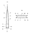
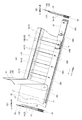
図1〜図4と図5(A)は本発明に係る自立型ガゼット付き包装用袋11の第一実施形態に関するものである。この自立型ガゼット付き包装用袋11については、以下に述べるそれぞれの実施形態において、単に包装用袋11ということがある。
1-4 and FIG. 5 (A) are related with 1st embodiment of the
図1〜図4と図5(A)に例示された包装用袋11は、後で説明する詳細内容からも明らかなように、前後一対のベースメンバ12・13と左右一対のシングル型サイドガゼット14・15と一つのダブル型ボトムガゼット16とを主要な構成要素(構成部材)にしている。これらのうちで両ベースメンバ12・13は、フィルム状とか、シート状とか、シートフィルム状とかいわれる薄い材料からなり、ほぼ四角形(四角形も含む)の外形を有するものである。両サイドガゼット14・15やボトムガゼット16も、両ベースメンバ12・13と同様の薄い材料からなるものである。このほか、ダブル型ボトムガゼット16については、後述からも明らかなように、シングル型からなる二つのボトムガゼット16F・16Rを合成することでダブル型を呈しているものである。
The
両ベースメンバ12・13と両サイドガゼット14・15とボトムガゼット16とを主要な構成要素とする包装用袋11については、種々の材質のものがある。その一つとして合成樹脂をあげることができ、他の一つとして金属箔(金属製フィルム)をあげることができる。さらに他の一つとして紙をあげることができる。これら以外のものとしては、合成樹脂・金属箔・紙のうちから選択された二つ以上の組み合わせによる複合材をあげることができる。典型的な一例に該当する合成樹脂製包装用袋11について、その場合の具体的な合成樹脂フィルムとしては、直鎖状低密度ポリエチレン(LLDPE)、高密度ポリエチレン(HDPE)、未延伸ポリプロピレン(CPP)、ポリアミド(PA)、ポリエステル(PET)、蒸着フィルム、ポリ塩化ビニールなどをあげることができ、これらのフィルムを複層数張り合わせたラミネート加工フィルムが包装用袋向けとして最も普及している。金属箔製の包装用袋11における具体的な金属箔としては、アルミ箔、銅箔、SUS箔(ステンレス箔)、鉄箔などをあげることができる。紙製の包装用袋11における具体的な紙としては和紙や洋紙を問わないが、とくには未晒包装紙や晒包装紙、合成紙などの包装紙をあげることができる。その代表的一例はクラフト紙である。複合材については、合成樹脂フィルムと紙とによるラミネート加工品、合成樹脂フィルムと金属箔とによるラミネート加工品、金属箔と紙とによるラミネート加工品、合成樹脂フィルムと紙と金属箔とによるラミネート加工品などをあげることができる。
The
図1〜図4と図5(A)に例示された包装用袋11の他の構成要素について、その一つは袋開口部側の気密性を高めるためのシール材17Fであり、他の一つは袋開口部を自在に閉じたり開いたりするためのチャック18である。シール材17Fやチャック18を採用するか否かについては自由度がある。したがってシール材17Fやチャック18の場合は、必要に応じて包装用袋11に設けられるものである。
One of the other components of the
上記シール材17Fは袋の幅方向に長いテープ状の形態をしている。シール材17Fの材質について具体的一例をあげると、それは熱接着性を有する合成樹脂である。ちなみに両ベースメンバ12・13が合成樹脂からなる場合、シール材17Fとしては、それと同じ合成樹脂か、または、それとは異なる合成樹脂が採用されたりする。シール材17Fは両サイドガゼット14・15の上端側の接着強度を高めたり、袋内部で引張応力が集中した際の剥離破袋(両サイドガゼット14・15の上端側における剥離破袋)を阻止したりするために設けられるものである。かかるシール材17Fは、両ベースメンバ12・13のうちのいずれか一方の内面に接着されるものであるが、図4を参照して、それがたとえばリア用ベースメンバ13である場合には、図4におけるリア用ベースメンバ13の開口部側の内面の一部がシール材接着部17Rに設定される。
The sealing
上記チャック18は周知のとおり、一対の咬合自在な雌部材19aと雄部材19bとからなるものである。この一対の雌部材19a・雄部材19bも、典型的な一例において合成樹脂製である。チャック18の材料である合成樹脂について具体的にいうと、それは低密度ポリエチレン、直鎖状低密度ポリエチレン、エチレン−酢酸ビニル共重合体、ポリプロピレンなどであり、これらのうちから適当な樹脂が選択される。ちなみにチャック11に柔軟さが要求される場合は、ポリエチレンまたはエチレン共重合体などの樹脂が望ましい。また、チャック11として伸びにくさが要求される場合は、ホモポリプロピレン、ブロックポリプロピレン、ランダムポリプロピレン(RPP)、プロピレン−エチレン−ブテン1ランダム三元共重合体、ポリオレフィン系特殊軟質樹脂(例:プライムポリマーTPOのようなTPO樹脂)などの熱可塑性樹脂や、これらの樹脂を混合した混合物が望ましい。かかるチャック18について、雌部材19aの場合は、テープ状をなすベース材の片面に凹形の雌爪が形成されており、雄部材19bの場合は、テープ状をなすベース材の片面に凸形の雄爪が形成されている。そして雌部材19aの雌爪と雄部材19bの雄爪とが咬合自在に対応するので、これらの咬合とその離脱とが自由に行えるのである。チャック18についてはこのほか、雌部材19aや雄部材19bが両ベースメンバ12・13の内面に一体形成されることもある。
As is well known, the
すでに述べたとおり、図1〜図4と図5(A)には、第一実施形態の包装用袋11が示されているものである。この包装用袋11における各構成要素の相対的な位置関係をいうと、フロント用ベースメンバ12は自明のように袋表部となる位置にあり、かつ、リア用ベースメンバ13も自明のように袋裏部となる位置にある。両ベースメンバ12・13の内面におけるそれぞれの上部側(袋の開口部側)には、チャック18の雌部材19aと雄部材19bとが設けられる。この場合の雌部材19aと雄部材19bについて、雌雄いずれの部材を前後いずれのベースメンバ12・13に設けるかについては自由である。ゆえに、雌部材19aや雄部材19bが設けられるベースメンバが図示例の逆になることもある。リア用ベースメンバ13の内面には、また、雄部材19b下のシール材接着部17Rにシール材17Fが施され、それによって両サイドガゼット14・15の上端側を含む領域が気密にシールされる。
As already described, FIGS. 1 to 4 and FIG. 5 (A) show the
ダブル型のボトムガゼット16は、所定の接着が完了するまで、図4のごとくシングル型のボトムガゼット16F・16Rとして互いに分離しているものである。シングル型の各ボトムガゼット16F・16Rには、袋内方へ折り込み可能な折り込み形状を有するものである。シングル型の各ボトムガゼット16F・16Rには、その両端部に貫通接着用の切除部16Hがそれぞれ形成されている。図4に示されているように、一方のボトムガゼット16Fはフロント用ベースメンバ12の下部内面側に位置するものであり、他方のボトムガゼット16Rはリア用ベースメンバ13の下部内面側に位置するものである。
The double-
左右それぞれのシングル型のサイドガゼット14・15も、袋内方へ折り込み可能な折り込み形状を有するものである。シングル型の各サイドガゼット14・15は図4で明らかなように、両ベースメンバ12・13の互いに対面する内面間にあってその両側部に位置するものであり、しかも、該各サイドガゼットの下部がそれぞれ両シングル型ボトムガゼット16F・16R間に介在するものである。
Each of the left and right single-
第一実施形態の包装用袋11や第二実施形態以降の包装用袋11については、その構成要素の材質いかんで、熱接着手段(ヒートシール手段)とか接着剤による接着手段とかが選択的に採用されて袋状に仕上げられる。とくに各構成要素が合成樹脂系のものであるときは熱接着手段の採用されることが多い。ちなみに、以下に述べる第一実施形態の包装用袋11の代表的一例では、各構成要素が合成樹脂系のものであるから、その主要部の接着または全部の接着に際して熱接着手段が採用される。より具体的にいうと、接着に関与する面を構成する部分の合成樹脂が熱接着性のものからなるとともに、接着に関与しない面を構成する部分の合成樹脂が非熱接着性のものからなり、この両合成樹脂がフィルム状ないしシート状に一体化されているものである。
Regarding the
第一実施形態の包装用袋11において上記各部位にある各構成要素は、それぞれの所定部が相対接着されて当該袋11を構成するものである。すなわち、袋表部に配されたフロント用ベースメンバ12と袋裏部に配されたリア用ベースメンバ13と袋両側部に配されたサイドガゼット14・15と袋底部に配されたボトムガゼット16F・16Rとが袋状に接着されて包装用袋11を構成しているのである。こうして構成された包装用袋11の場合、袋両側部(左側部と右側部)のそれぞれには構成材料相互の接着部として上下方向に沿う二つのサイドリブ(合計四つ)が存するものであるとともに、袋底部にも構成材料相互の接着部として幅方向に沿う三つのボトムリブが存するものである。図1〜図3において、四つのサイドリブには符号31〜34が付されており、三つのボトムリブには符号35〜37が付されている。この場合における三つのボトムリブ35〜37、すなわちフロントボトムリブ35・センターボトムリブ36・リアボトムリブ37は、それぞれ図示のとおりの自立構造を有していて袋用スタンドの一部を構成するものである。この三つのボトムリブ35〜37が外側や内側に位置することに鑑みた場合、外側二つのボトムリブ35・37についてはアウターリブということができ、内側一つのボトムリブ36についてはインナーリブということができる。この場合の接着について、さらにいうと、シングル型の各ボトムガゼット16F・16Rがセンターボトムリブ36の部分で相互に接着されたことで、ダブル型のボトムガゼット16になるものである。
In the
第一実施形態の包装用袋11については、また、上記各部位にある各構成要素がつぎのようにも接着されて四つのコーナボトムリブ41〜44が形成されるものである。そのうちの一つ目である袋下部側にある左前下隅部について、当該左前下隅部には、フロント用ベースメンバ12の左下隅部と左サイドガゼット14の下端前部とボトムガゼット16の左端前部とを接着一体化してなる左前コーナボトムリブ41が形成される。そのうちの二つ目である袋下部側にある右前下隅部について、当該右前下隅部には、フロント用ベースメンバ12の右下隅部と右サイドガゼット15の下端前部とボトムガゼット16の右端前部とを接着一体化してなる右前コーナボトムリブ42が形成される。そのうちの三つ目である袋下部側にある左後下隅部について、当該左後下隅部には、リア用ベースメンバ13の左下隅部と左サイドガゼット14の下端後部とボトムガゼット16の左端後部とを接着一体化してなる左後コーナボトムリブ43が形成される。そのうちの四つ目である袋下部側にある右後下隅部について、当該右後下隅部には、リア用ベースメンバ13の右下隅部と右サイドガゼット16の下端後部とボトムガゼット16の右端後部とを接着一体化してなる右後コーナボトムリブ44が形成される。このようにして形成された左前・右前・左後・右後の各コーナボトムリブ41〜44も自立構造を有している。該各コーナボトムリブ41〜44は袋用スタンドの残部を構成するものであるとともに、ボトムガゼット16の広がりに対する抵抗部をも兼ねるものである。各コーナボトムリブ41〜44がこのような抵抗部になる理由は、上記の接着一体化によって分厚くなるとともに他部よりも硬いものになり、それによって変形のしがたい剛性を獲得するからである。それゆえボトムガゼット16が広がろうとするときには、これに抗してボトムガゼット広がりを抑制するのである。
About the
各サイドリブ31〜34・各ボトムリブ35〜37・各コーナボトムリブ41〜44などは、それぞれの構成要素を上記のように接着することで生じるものである。その際の具体的一例としては図1・図3で明らかなように、両ベースメンバ12・13の一部(側縁の下方部)と両サイドガゼット14・15の一部(側縁の下方部)とが各ボトムガゼット16F・16Rの切除部16Hを通じて直接接着されるものである。また、袋下部の四隅には、三角形状のコーナ接着部45がそれぞれ形成される。四つある各コーナ接着部45については、それぞれ対応するコーナボトムリブ41〜44と連続しているので、その連続するコーナボトムリブ41〜44の一部に含まれるものである。
Each of the
包装用袋11の第一実施形態として図1〜図4に例示されたものは、縦(上下方向)に長く、幅(左右方向)が狭く、厚み(前後方向)が小さいものであることから、一例として「茶葉」の包装に用いられるものである。もちろん、この場合の寸法・仕様などを変更することで、たとえば「ふりかけ食品」の包装にも適用することができ、その他の被包装物であっても、扁平包装状態での自立を要するものであれば、それらに適用することができる。
1 to 4 illustrated as the first embodiment of the
第一実施形態の包装用袋11において、シングル型のサイドガゼット14・15におけるシングル襠幅をSとし、ダブル型のボトムガゼット16におけるダブル襠幅をWとした場合、Sが0.3W〜1Wの範囲内にあるのがよく、とくに、Sが0.5W〜0.8Wの範囲内にあるのが望ましい。その理由は、SとWとがこのような数値範囲の関係にあることにより、扁平包装を維持することができるからである。
In the
第一実施形態の包装用袋11において、シングル型のサイドガゼット14・15におけるシングル襠幅をSとし、フロント用ベースメンバ12やリア用ベースメンバ13の幅をそれぞれHとし、フロント用ベースメンバ12やリア用ベースメンバ13の高さをそれぞれTとした場合、Hが1S〜7Sの範囲内にあって、Tが0.5H〜4Hの範囲内にあるのが望ましい。これは、襠幅Sを基準にして袋丈(T)や袋幅(H)がこのような範囲にあれば、各種サイズの包装用袋11において扁平包装を維持できることとなる。
In the
上記において、襠幅Sはサイドガゼット14・15の有効襠幅をさすものであり、襠幅Wもボトムガゼット16の有効襠幅をさすものである。さらに有効襠幅は、それぞれの襠が最大限度まで広がったときの襠幅をさすものである。
In the above description, the heel width S indicates the effective heel width of the
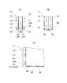
第一実施形態の包装用袋11において、袋底部のダブル型ボトムガゼット構造は、二つのシングル型ボトムガゼット16F・16Rを接合することで、その種のダブル型にしたものである。このタイプのものについては、図5(B)のような変形例もある。ちなみに図5(A)(B)に図示されたものついていうと、同図の(A)が前述した第一実施形態のもの、同図の(B)がその変形例である。
In the
図5(B)を参照して、この図示例のボトムガゼット16は、これ単独でダブル型をなすものである。このダブル型のボトムガゼット16も、既述の実施形態に準じて両ベースメンバ12・13や両サイドガゼット14・15と接着されるのであるが、これには、シングル型ボトムガゼット16F・16Rの場合のようなボトムガゼット相互の接着がないのである。図5(A)(B)の両包装用袋11にはこのような差異があるものの、自立型の扁平包装という点からすると、両者には実質的な差異がない。
Referring to FIG. 5B, the
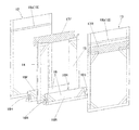
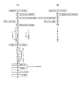
図1〜図5(A)の包装用袋11については、一例にすぎない例示の図6(A)と図7の製造方法でつくられる。周知のとおり、製造ライン上に設備されたフロント用ベースメンバ12の供給部やリア用ベースメンバ13の供給部には、ベースメンバ用の原反ロールがそれぞれセットされているのである。この両供給部からは、連続状態にあるフロント用ベースメンバ12やリア用ベースメンバ13が所定方向へ巻き戻し供給されてそれぞれが所定位置で重なり合うように対面合流するのである。その一方において各構成要素の供給部からは、所要の各材料(サイドガゼット14・15・ボトムガゼット16F・16R・シール材17Fとなる各材料)が製造ラインの所定位置から適時供給され、これらに対して所要の処理が施されるのである。図6(A)はその際の製造ラインの要部を示し、図7はその際の製造状況の要部を示している。この両図を参照して明らかなように、連続したリア用ベースメンバ13の上面(袋状態での内面)には、下記のものが下記に述べるようにして供給配置される。そのうちの一つ目は、連続状態にあるボトムガゼット16R用の材料(ボトムガゼット16Rの長尺材料)である。この長尺ボトムガゼット16Rは図7のごとく、連続リア用ベースメンバ13の一側縁に沿ってその上に供給配置される。その二つ目は、両サイドガゼット14・15の一体化材料である。このサイドガゼット一体化材料は矩形シート材を筒状に巻いて扁平化したものである。このサイドガゼット一体化材料については、その中心線のところで等分することにより、二つのサイドガゼット14・15に切り分けることができるものである。かかるサイドガゼット一体化材料は、連続状リア用ベースメンバ13の進行方向(メインの製造ライン)と直交する方向から当該リア用ベースメンバ13上に供給配置される。その際、このサイドガゼット一体化材料の一端部は、図7のごとく長尺ボトムガゼット16Rの材料上に乗る。その三つ目は、上記と同様、連続状態にあるボトムガゼット16F用の材料(ボトムガゼット16Fの長尺材料)である。この長尺ボトムガゼット16Fも図7のごとく、連続リア用ベースメンバ13の一側縁に沿ってその上に供給配置され、サイドガゼット一体化材料の一端部上に重なる。これによって、サイドガゼット一体化材料の一端部は二つの長尺ボトムガゼット16R・16Fで上下から挟まれることとなる。その四つ目は、連続状態にあるシール材17F用の材料(シール材17Fの長尺材料)である。この長尺シール材17Fは図7のごとく、連続リア用ベースメンバ13の他側縁に沿ってその上に供給配置される。それで長尺シール材17Fは、サイドガゼット一体化材料の他端部上に重なる。図6(A)や図7を参照して、それぞれの材料がこの状態にまで合流したときには、図6(A)に示す長尺シール材17Fのシール処理が行われる。このシール処理はメインの製造ラインに沿うもの、すなわち、メインの製造ラインに平行するところの平行シール処理である。この平行シール処理では、メイン製造ラインに沿って細長い形状をした平行シールバーが用いられる。さらにいうと、所定温度に加熱された平行シールバーが長尺シール材17Fの上から押し付けられ、これにより、連続リア用ベースメンバ13とサイドガゼット一体化材料の他端部と長尺シール材17Fとが加熱加圧接着されて一体化する。この直後、かかる接着部分が図6(A)に示すごとく冷却処理される。この冷却処理の際には、平行シールバーの場合と同様、メイン製造ライン沿いに細長い形状をした平行冷却バーが用いられ、当該平行冷却バーが上記る接着部分に押し当てられる結果、その接着部分が所定の温度まで冷却される。図6(A)を参照してこの後、ローラRXを経由して到来する連続フロント用ベースメンバ12が連続リア用ベースメンバ13と対面合流する。すなわち、所要の各構成要素を配給された後の連続リア用ベースメンバ13に対し、その上面から覆い被さるようにして連続フロント用ベースメンバ12が重なるのである。この段階までを経たとき、図7に示す直交シール処理と直交冷却処理とが行われる。そのうちの直交シール処理についていうと、これにはメイン製造ラインと直交する方向に細長い形状をした直交シールバーが用いられる。この直交シールバーは、上記ローラRXよりもライン後方にあってライン上面に向けて降下したり上昇復帰したりするものである。そして図6(A)に示す上記サイドガゼット一体化材料(その中心線のところ)が直交シールバー下まで進行してくるのと同期して、直交シールバーが連続フロント用ベースメンバ12の上から押し付けられる(その押し付け部位はサイドガゼット一体化材料が位置するところ)。これにより、連続リア用ベースメンバ13とサイドガゼット一体化材料と長尺シール材17Fと連続フロント用ベースメンバ12とが加熱加圧接着されて一体化する。この際、連続リア用ベースメンバ13と連続フロント用ベースメンバ12とは、既述の切除部16Hを通じて接着状態になる。直交シール処理後の直交冷却処理では、直交シールバーの場合と同様、メイン製造ラインと直交する方向に細長い形状をした直交冷却バーが用いられ、当該直交冷却バーが上記る接着部分に押し当てられることで、その接着部分が所定の温度まで冷却される。以下は図6(A)に示すところのカッティング処理やトリミング処理が施される。そのうちのカッティング処理では、メイン製造ラインと直交する方向に細長い形状であってライン上面に向けて降下したり上昇復帰したりするカッターが用いられ、かつ、そのカッターにより、上記サイドガゼット一体化材料の中心線のところを切断箇所とするカッティングが行われる。かくて一袋ごとの包装用袋11が得られる。その後のトリミング処理では、不要部分の切除や袋形態を整えるためのトリミングが行われる。
The
上述した図6(A)・図7の製造方法は、図1〜図5(A)の包装用袋11を製造する際の一例であるが、当該製造方法を一部変更するだけで、図5(B)の包装用袋11も製造することができる。その図5(B)の包装用袋11を製造する例について、図6(B)と図8を参照して要点のみ説明する。
The manufacturing method of FIG. 6 (A) and FIG. 7 described above is an example when manufacturing the
図5(B)の包装用袋11を製造する場合についていうと、このときに用いられるボトムガゼット用材料はシングル型ではなく、ダブル型ボトムガゼット16用の長尺材料である。図5(A)(B)の各包装用袋11を製造するときの主な相違はこの点だけである。以下、この相違点に着目して図5(B)の包装用袋11の製造例について、図6(B)と図8を参照して説明する。
In the case of manufacturing the
図6(B)と図8とくに図8を参照して明らかなように、連続供給されるリア用ベースメンバ13の一側縁上には、ダブル型の長尺ボトムガゼット16が供給配置される。その後、両サイドガゼット14・15の一体化材料が、連続状リア用ベースメンバ13の進行方向(メインの製造ライン)と直交する方向から当該リア用ベースメンバ13上に供給配置される。その際、このサイドガゼット一体化材料の一端部は、図8のごとくダブル型長尺ボトムガゼット16の中央折り込み部内に進入するのである。この場合において、当該型長尺ボトムガゼット16の中央折り込み部内に進入する各サイドガゼット一体化材料の一端部には、図8で明らかなように、長尺ボトムガゼット16の貫通接着用切除部16Hと合致する孔状の切除部16Wが形成されている。この切除部16Wも貫通接着用のものである。この後は前製造例の場合と同様、長尺シール材17Fが連続リア用ベースメンバ13の他側縁に沿ってその上に供給配置され、それが前製造例と同様にヒートシールされる。これ以降も前製造例の場合と実質的に同様のプロセスを経ることとなり、それによって図5(B)の包装用袋11が製造されるのである。したがって、図5(B)の各包装用袋11に関する製造について、これ以降のプロセスは、前製造例の内容を参照することでその説明を省略するものである。
As apparent from FIG. 6B and FIG. 8 with particular reference to FIG. 8, a double
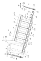
図9は本発明に係る自立型ガゼット付き包装用袋11の第二実施形態に関するものである。第二実施形態の包装用袋11も、両サイドガゼット14・15がシングル型、ボトムガゼット16がダブル型というものであるから、その基本的な構成は第一実施形態のそれと変わるところがない。さらに袋両側部に各サイドリブ31〜34が存すること、袋底部に各ボトムリブ35〜37が存すること、各コーナボトムリブ41〜44が存することなども、第一実施形態のものと実質的に同じである。図9の包装用袋11について、さらにいうと、自立構造を有するフロントボトムリブ35やリアボトムリブ37などのアウターボトムリブが自立構造を有していて袋用スタンドの一部を兼ね、かつ、各コーナボトムリブ41〜44も自立構造を有していて袋用スタンドの一部を兼ねるものである。
FIG. 9 relates to the second embodiment of the
図9に例示する第二実施形態の包装用袋11が第一実施形態のそれと異なるのは、センターボトムリブ(中央ボトムリブと同義)36を含む袋底面部21である。すなわち、第二実施形態の包装用袋11におけるセンターボトムリブ36は、倒伏自在な非自立構造となっている。そして当該センターボトムリブ36を含む袋底面部20が袋載置面に対して接するものとなっている。さらに第二実施形態の包装用袋11では、各コーナボトムリブ41〜44の中央部に、ガゼット広がりを容易にするための切り離し部21〜24が設けられている。この各切り離し部21〜24は、たとえばトリミング処理において各コーナボトムリブ41〜44の所定部を切除することにより形成されるものである。
The
第二実施形態の包装用袋11におけるその他の事項は、第二実施形態の包装用袋11で述べた内容と実質的に同一かそれに準ずるものである。したがって、第二実施形態の包装用袋11におけるその他の事項は、第一実施形態の包装用袋11で述べた内容を参照することで説明を省略するものである。
Other matters in the
上記第二実施形態やつぎの第三実施形態で使用する用語のうちで、「袋載置面」とは、各種の取り扱いに際して包装用袋11をスタンディング状態で載せ置くときの面をいうものである。具体的には、商品陳列棚の上面(棚面)とかテーブルの上面とかがこれに該当する。
Among the terms used in the second embodiment and the next third embodiment, the “bag placing surface” refers to a surface when the
図9に例示する第二実施形態の包装用袋11で各コーナボトムリブ41〜44には、ガゼット広がりに対する抵抗機能が実質的になく、その襠幅の範囲内であれば容易に広がるものである。その理由の一つは、包装用袋11の袋底面部21において、センターボトムリブ36を境界にして前後二つある袋底面部21が、いずれもガゼット広がりの容易な船底形状をしているからである。この船底形状については周知のとおり、袋底面部21の両側部が袋両側部に向けて傾斜面または弯曲面で迫り上がるという形状のものである。他の理由の一つは、ガゼット広がりを容易にするための切り離し部21〜24が各コーナボトムリブ41〜44に設けられているからである。
In the
図9に例示する第二実施形態の包装用袋11は、両サイドガゼット14・15やダブル型のボトムガゼット16がよく広がる膨満包装タイプであるから、被包装物の収容量を高い。それに、倒伏自在な非自立構造のセンターボトムリブ36を含む袋底面部20が袋載置面に対してしっかりと接地するから自立安定性も高いとともに、袋底面部20にあてがわれたセンターボトムリブ36が、そのプロテクト効果によって当該袋底面部20を防護することとなる。
The
図10は本発明に係る自立型ガゼット付き包装用袋11の第三実施形態に関するものである。第三実施形態の包装用袋11も、両サイドガゼット14・15がシングル型、ボトムガゼット16がダブル型というものであるから、その基本的な構成は第一実施形態や第二実施形態のそれと変わるところがない。さらに袋両側部に各サイドリブ31〜34が存すること、袋底部に各ボトムリブ35〜37が存することなども、第一実施形態や第二実施形態のものと実質的に同じである。
FIG. 10 relates to a third embodiment of the
図10に例示する第三実施形態の包装用袋11が各前例のものと異なるのは、袋底部にある三つのボトムリブ35〜37がいずれも倒伏自在な非自立構造のものであること、しかも、前述したような自立構造の各コーナボトムリブ41〜44が存しないことである。図10の包装用袋11は、また、フロントボトムリブ(前側のボトムリブ)35とリアボトムリブ(後側のボトムリブ)37とが、それぞれフロント用ベースメンバ12の下端やリア用ベースメンバ13の下端から外向き折れ曲がって張り出した袋自立用の支持フラップを兼ねるものである。したがって以下において、第三実施形態の包装用袋11におけるフロントボトムリブ35とリアボトムリブ37については、支持フラップということもある。図10の包装用袋11では、さらに、非自立構造のセンターボトムリブ(中央のボトムリブ)36がプロテクト効果のあるフラップとして袋底面部21にあてがわれるものである。
The
図10の包装用袋11において、ダブル型のボトムガゼット16しても、シングル型のボトムガゼット16F・16Rにしても、これには前述した切除部16Hがない。この切除部16Hがないゆえ、両サイドガゼット14・15の一部が直接接着されることもないのである。したがって三つのボトムリブ35〜37のそれぞれ両側部は、互いに分離しているのである。さらに図10の包装用袋11においては、両サイドガゼット14・15とボトムリブ16との接着部が、図10(D)のごとき部分的なトリミング処理で一部が凹形(V字形またはU字形など)に切除されている。ここでは、これを重なり回避部51と称する。かかる重なり回避部51は、各ボトムリブ35〜37を倒伏状態にした際の不必要なフラップ重なりをできるだけ少なくするため、また、センターボトムリブ36の倒伏を容易にするための技術的配慮によるものである。
In the
第三実施形態の包装用袋11におけるその他の事項は、第一実施形態や第二実施形態の包装用袋11で述べた内容と実質的に同一かそれに準ずるものである。したがって、第三実施形態の包装用袋11におけるその他の事項は、第一実施形態や第二実施形態の包装用袋11で述べた内容を参照することで説明を省略するものである。
Other matters in the
図10に例示する第三実施形態の包装用袋11も、両サイドガゼット14・15やダブル型のボトムガゼット16がよく広がる膨満包装タイプであるから、被包装物の収容量を高い。しかも、倒伏自在な非自立構造のセンターボトムリブ36を含む袋底面部20が袋載置面に対してしっかりと接地する上、フロントボトムリブ35やリアボトムリブ37が袋前後に張り出し接地した支持フラップとなるものであるから、自立安定性がより高いものになる。さらに、袋底面部20にあてがわれたセンターボトムリブ36が、前例と同様のプロテクト効果によって当該袋底面部20を防護することとなる。
The
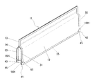
図11に例示する第四実施形態の包装用袋11は、扁平包装を維持しながら安定自立性を発揮するという第一実施形態とタイプものについて、他の一例を示したものである。この第四実施形態の包装用袋11が第一実施形態のそれと異なる点は、第一実施形態のものが縦長、それに対して第四実施形態のものが横長ということである。この縦長・横長の相違点を除き、第四実施形態の包装用袋11は第一実施形態のそれと実質的に同一かそれに準ずるものである。したがって、第四実施形態の包装用袋11におけるその他の事項は、第一実施形態や第二実施形態の包装用袋11で述べた内容を参照することで説明を省略するものである。
The
第四実施形態として示す横長タイプの包装用袋11は、たとえば、細長いスティック状の菓子・パスタなどの食品の包装に適している。もちろん食品以外の細長い商品なども包装することができる。このタイプの包装用袋11は、被包装物を入れて陳列などした場合に、転倒のおそれが皆目ないので望ましい。
The horizontally
このほか、第二実施形態や第三実施形態の包装用袋11も、縦長ものや横長のものが、その設計変更の範囲内であり得る。また、第二実施形態〜第四実施形態の各包装用袋11についても、既述の内容を主体にした本発明の製造方法によって製造することができるものである。
In addition, the
本発明に係る自立型ガゼット付き包装用袋は、扁平包装タイプや膨満包装タイプのいずれであっても自立安定性が高く、しかも、構造の簡潔性・強度・低価格などを満足させるものであるから、産業上の利用可能性が高いといえる。 The packaging bag with a self-supporting gusset according to the present invention has high self-supporting stability regardless of whether it is a flat packaging type or an inflated packaging type, and satisfies the simplicity, strength, and low price of the structure. Therefore, it can be said that the industrial applicability is high.
本発明に係る自立型ガゼット付き包装用袋の製造方法は、当該包装用袋の製造に関し、イニシャルコストの抑制・ランニングコストの抑制・高歩留まり・安定量産性を期すことのできるので、この分野での貢献度が高いものである。 The method for manufacturing a packaging bag with a self-supporting gusset according to the present invention can reduce the initial cost, the running cost, the high yield, and the stable mass productivity with respect to the manufacturing of the packaging bag. The contribution of is high.
11 包装用袋
12 フロント用ベースメンバ
13 リア用ベースメンバ
14 サイドガゼット
15 サイドガゼット
16 ボトムガゼット(ダブル型)
16F ボトムガゼット(シングル型)
16R ボトムガゼット(シングル型)
16H 切除部
16W 切除部
17F シール材
18 チャック
19a 雌部材
19b 雄部材
20 袋底面部
21 切り離し部
22 切り離し部
23 切り離し部
24 切り離し部
31 サイドリブ
32 サイドリブ
33 サイドリブ
34 ボトムリブ
35 ボトムリブ(フロントボトムリブ)
36 ボトムリブ(センターボトムリブ・中央ボトムリブ)
37 リアボトムリブ
41 コーナボトムリブ
42 コーナボトムリブ
43 コーナボトムリブ
44 コーナボトムリブ
45 コーナ接着部
51 重なり回避部
11
16F Bottom gusset (single type)
16R Bottom gusset (single type)
36 Bottom rib (Center bottom rib, Center bottom rib)
37
Claims (9)
袋表部に配されたフロント用ベースメンバと袋裏部に配されたリア用ベースメンバと袋両側部に配されたサイドガゼットと袋底部に配されたボトムガゼットとが袋状に接着されていること、および、
袋両側部のそれぞれには構成材料相互の接着部として上下方向に沿う二つのサイドリブが存するものであるとともに、袋底部にも構成材料相互の接着部として幅方向に沿う三つのボトムリブが存するものであること
を前提とする包装用袋において、
袋底部にある三つのボトムリブがそれぞれ自立構造を有していて袋用スタンドの一部を構成するものであること、および、
袋下部側にある左前下隅部について、この左前下隅部には、フロント用ベースメンバの左下隅部と左サイドガゼットの下端前部とボトムガゼットの左端前部とを接着一体化してなる左前コーナボトムリブが形成されていること、および、
袋下部側にある右前下隅部について、右前下隅部には、フロント用ベースメンバの右下隅部と右サイドガゼットの下端前部とボトムガゼットの右端前部とを接着一体化してなる右前コーナボトムリブが形成されていること、および、
袋下部側にある左後下隅部について、左後下隅部には、リア用ベースメンバの左下隅部と左サイドガゼットの下端後部とボトムガゼットの左端後部とを接着一体化してなる左後コーナボトムリブが形成されていること、および、
袋下部側にある右後下隅部について、右後下隅部には、リア用ベースメンバの右下隅部と右サイドガゼットの下端後部とボトムガゼットの右端後部とを接着一体化してなる右後コーナボトムリブが形成されていること、および、
左前・右前・左後・右後の各コーナボトムリブが自立構造を有していて袋用スタンドの残部を構成するものであるとともに、ボトムガゼット広がりに対する抵抗部をも兼ねるものであること
を特徴とする自立型ガゼット付き包装用袋。 A front base member that forms a sheet, which forms the front of the bag, a rear base member that forms a sheet, and forms both sides of the bag. A single-type side gusset that can be folded inward of the bag, and a double-type bottom gusset that constitutes both sides of the bag and can be folded inward of the bag. And
A front base member disposed on the front surface of the bag, a rear base member disposed on the back of the bag, side gussets disposed on both sides of the bag, and a bottom gusset disposed on the bottom of the bag are bonded together in a bag shape. And
Each side of the bag has two side ribs along the vertical direction as an adhesive part between the constituent materials, and three bottom ribs along the width direction as an adhesive part between the constituent materials also at the bag bottom. In packaging bags that are assumed to be
The three bottom ribs at the bottom of the bag each have a self-supporting structure and constitute part of the bag stand; and
About the lower left front corner on the lower side of the bag, the lower left front corner is formed by bonding and integrating the lower left corner of the front base member, the lower front of the left side gusset, and the lower left front of the bottom gusset. That ribs are formed, and
For the lower right front corner on the lower side of the bag, the lower right front corner has a right front corner bottom rib formed by bonding and integrating the lower right corner of the front base member, the lower end front of the right side gusset, and the right end front of the bottom gusset. Is formed, and
For the lower left corner on the lower bag side, the lower left corner is the left rear corner bottom formed by bonding and integrating the lower left corner of the rear base member, the lower end rear of the left side gusset, and the rear left end of the bottom gusset. That ribs are formed, and
For the lower right rear corner on the lower side of the bag, the lower right rear corner is formed by bonding and integrating the lower right corner of the rear base member, the lower end rear of the right side gusset, and the right rear end of the bottom gusset. That ribs are formed, and
Each of the front left, right front, left rear, and right rear corner bottom ribs has a self-supporting structure and constitutes the remaining part of the bag stand, and also serves as a resistance to the spread of the bottom gusset A self-supporting packaging bag with a gusset.
袋表部に配されたフロント用ベースメンバと袋裏部に配されたリア用ベースメンバと袋両側部に配されたサイドガゼットと袋底部に配されたボトムガゼットとが袋状に接着されていること、および、
袋両側部のそれぞれには構成材料相互の接着部として上下方向に沿う二つのサイドリブが存するものであるとともに、袋底部にも構成材料相互の接着部として幅方向に沿う三つのボトムリブが存するものであること
を前提とする包装用袋において、
袋底部にある三つのボトムリブのうち、その中央のボトムリブを除く二つのボトムリブが自立構造を有していて袋用スタンドの一部を兼ねるものであり、かつ、中央のボトムリブが倒伏自在な非自立構造のものであること、および、
袋下部側にある左前下隅部について、この左前下隅部には、フロント用ベースメンバの左下隅部と左サイドガゼットの下端前部とボトムガゼットの左端前部とを接着一体化してなる左前コーナボトムリブが形成されていること、および、
袋下部側にある右前下隅部について、右前下隅部には、フロント用ベースメンバの右下隅部と右サイドガゼットの下端前部とボトムガゼットの右端前部とを接着一体化してなる右前コーナボトムリブが形成されていること、および、
袋下部側にある左後下隅部について、左後下隅部には、リア用ベースメンバの左下隅部と左サイドガゼットの下端後部とボトムガゼットの左端後部とを接着一体化してなる左後コーナボトムリブが形成されていること、および、
袋下部側にある右後下隅部について、右後下隅部には、リア用ベースメンバの右下隅部と右サイドガゼットの下端後部とボトムガゼットの右端後部とを接着一体化してなる右後コーナボトムリブが形成されていること、および、
左前・右前・左後・右後の各コーナボトムリブが自立構造を有していて袋用スタンドの残部を構成するものであること、および、
倒伏自在な非自立構造の中央ボトムリブを含む袋底面部が袋載置面に対して接するものであること
を特徴とする自立型ガゼット付き包装用袋。 A front base member that forms a sheet, which forms the front of the bag, a rear base member that forms a sheet, and forms both sides of the bag. A single-type side gusset that can be folded inward of the bag, and a double-type bottom gusset that constitutes both sides of the bag and can be folded inward of the bag. And
A front base member disposed on the front surface of the bag, a rear base member disposed on the back of the bag, side gussets disposed on both sides of the bag, and a bottom gusset disposed on the bottom of the bag are bonded together in a bag shape. And
Each side of the bag has two side ribs along the vertical direction as an adhesive part between the constituent materials, and three bottom ribs along the width direction as an adhesive part between the constituent materials also at the bag bottom. In packaging bags that are assumed to be
Of the three bottom ribs at the bottom of the bag, the two bottom ribs except for the central bottom rib have a self-supporting structure that also serves as a part of the bag stand, and the central bottom rib is a free-standing non-independent Being of structure, and
About the lower left front corner on the lower side of the bag, the lower left front corner is formed by bonding and integrating the lower left corner of the front base member, the lower front of the left side gusset, and the lower left front of the bottom gusset. That ribs are formed, and
For the lower right front corner on the lower side of the bag, the lower right front corner has a right front corner bottom rib formed by bonding and integrating the lower right corner of the front base member, the lower end front of the right side gusset, and the right end front of the bottom gusset. Is formed, and
For the lower left corner on the lower bag side, the lower left corner is the left rear corner bottom formed by bonding and integrating the lower left corner of the rear base member, the lower end rear of the left side gusset, and the rear left end of the bottom gusset. That ribs are formed, and
For the lower right rear corner on the lower side of the bag, the lower right rear corner is formed by bonding and integrating the lower right corner of the rear base member, the lower end rear of the right side gusset, and the right rear end of the bottom gusset. That ribs are formed, and
Each of the front left, right front, left rear, and right rear corner bottom ribs has a self-supporting structure and constitutes the remainder of the bag stand, and
A packaging bag with a self-supporting gusset, wherein the bottom surface of the bag including the center bottom rib of a non-self-supporting structure that can be laid down is in contact with the bag mounting surface.
袋表部に配されたフロント用ベースメンバと袋裏部に配されたリア用ベースメンバと袋両側部に配されたサイドガゼットと袋底部に配されたボトムガゼットとが袋状に接着されていること、および、
袋両側部のそれぞれには構成材料相互の接着部として上下方向に沿う二つのサイドリブが存するものであるとともに、袋底部にも構成材料相互の接着部として幅方向に沿う三つのボトムリブが存するものであること
を前提とする包装用袋において、
袋底部にある三つのボトムリブがいずれも倒伏自在な非自立構造のものであり、かつ、そのうちで中央のボトムリブを除く前側のボトムリブと後側のボトムリブとが、それぞれフロント用ベースメンバの下端やリア用ベースメンバの下端から外向き折れ曲がって張り出した袋自立用の支持フラップを兼ねるものであること、および、
倒伏自在な非自立構造の中央ボトムリブを含む袋底面部と二つの支持フラップとが袋載置面に対して接するものであること
を特徴とする自立型ガゼット付き包装用袋。 A front base member that forms a sheet and forms a sheet, a rear base member that forms a sheet and forms a sheet, and both sides of the bag A single-type side gusset that can be folded inward of the bag and a double-type bottom gusset that can be folded inward of the bag. And
A front base member disposed on the front surface of the bag, a rear base member disposed on the back of the bag, side gussets disposed on both sides of the bag, and a bottom gusset disposed on the bottom of the bag are bonded together in a bag shape. And
Each side of the bag has two side ribs along the vertical direction as an adhesive part between the constituent materials, and three bottom ribs along the width direction as an adhesive part between the constituent materials also at the bag bottom. In packaging bags that are assumed to be
The three bottom ribs at the bottom of the bag are all free-standing, and the front bottom rib and the rear bottom rib excluding the center bottom rib are the bottom and rear of the front base member, respectively. Serving as a support flap for bag self-supporting that is bent outward from the lower end of the base member, and
A packaging bag with a self-supporting gusset, characterized in that a bag bottom surface portion including a central bottom rib of a self-supporting structure that can be laid down and two support flaps are in contact with the bag mounting surface.
フロント用ベースメンバとリア用ベースメンバとの間であって当該両ベースメンバの両側部に該当する箇所には、一対のシングル型サイドガゼットを介在させること、および、 フロント用ベースメンバとリア用ベースメンバとの間であって当該両ベースメンバの底部に該当する箇所、しかも、フロント用ベースメンバと両サイドガゼットとの間やリア用ベースメンバと両サイドガゼットとの間には、シングル型のボトムガゼットをそれぞれ介在させること、および、
上記各構成材料相互の互いに対応する箇所を熱接着手段で接着することにより、袋両側部にシングル型のサイドガゼット構造を形成するとともに、袋下部にダブル型のボトムガゼット構造を形成すること
を特徴とする自立型ガゼット付き包装用袋の製造方法。 In the method for manufacturing the packaging bag with a self-supporting gusset according to any one of claims 1 to 7,
A pair of single-type side gussets are interposed between the front base member and the rear base member and corresponding to both sides of the base members, and the front base member and the rear base A single-type bottom between a member and a portion corresponding to the bottom of both base members, between a front base member and both side gussets, and between a rear base member and both side gussets. Interposing gussets respectively, and
The parts corresponding to each other of the above-mentioned constituent materials are bonded to each other by heat bonding means, thereby forming a single type side gusset structure on both sides of the bag and a double type bottom gusset structure on the lower part of the bag. The manufacturing method of the packaging bag with a self-supporting gusset.
フロント用ベースメンバとリア用ベースメンバとの間であって当該両ベースメンバの両側部に該当する箇所には、一対のシングル型サイドガゼットを介在させること、および、 フロント用ベースメンバとリア用ベースメンバとの間であって当該両ベースメンバの底部に該当する箇所には、ダブル型のボトムガゼットを介在させるとともに、そのダブル型ボトムガゼットの中央折り込み部内に両サイドガゼットの下端部を介在させること、および、
上記各構成材料相互の互いに対応する箇所を熱接着手段で接着することにより、袋両側部にシングル型のサイドガゼット構造を形成するとともに、袋下部にダブル型のボトムガゼット構造を形成すること
を特徴とする自立型ガゼット付き包装用袋の製造方法。 In the method for manufacturing the packaging bag with a self-supporting gusset according to any one of claims 1 to 7,
A pair of single-type side gussets are interposed between the front base member and the rear base member and corresponding to both sides of the base members, and the front base member and the rear base A double-type bottom gusset is interposed at a position between the members and corresponding to the bottoms of both base members, and the lower ends of both side gussets are interposed in the central folding portion of the double-type bottom gusset. ,and,
The parts corresponding to each other of the above-mentioned constituent materials are bonded to each other by heat bonding means, thereby forming a single type side gusset structure on both sides of the bag and a double type bottom gusset structure on the lower part of the bag. The manufacturing method of the packaging bag with a self-supporting gusset.
Priority Applications (1)
| Application Number | Priority Date | Filing Date | Title |
|---|---|---|---|
| JP2011113377A JP5420589B2 (en) | 2011-05-20 | 2011-05-20 | Packaging bag with self-supporting gusset and its manufacturing method |
Applications Claiming Priority (1)
| Application Number | Priority Date | Filing Date | Title |
|---|---|---|---|
| JP2011113377A JP5420589B2 (en) | 2011-05-20 | 2011-05-20 | Packaging bag with self-supporting gusset and its manufacturing method |
Related Child Applications (1)
| Application Number | Title | Priority Date | Filing Date |
|---|---|---|---|
| JP2013042940A Division JP5563116B2 (en) | 2013-03-05 | 2013-03-05 | Packaging bag with self-supporting gusset and its manufacturing method |
Publications (2)
| Publication Number | Publication Date |
|---|---|
| JP2012240718A true JP2012240718A (en) | 2012-12-10 |
| JP5420589B2 JP5420589B2 (en) | 2014-02-19 |
Family
ID=47462825
Family Applications (1)
| Application Number | Title | Priority Date | Filing Date |
|---|---|---|---|
| JP2011113377A Active JP5420589B2 (en) | 2011-05-20 | 2011-05-20 | Packaging bag with self-supporting gusset and its manufacturing method |
Country Status (1)
| Country | Link |
|---|---|
| JP (1) | JP5420589B2 (en) |
Citations (8)
| Publication number | Priority date | Publication date | Assignee | Title |
|---|---|---|---|---|
| JPS54113811U (en) * | 1978-01-24 | 1979-08-10 | ||
| JPS5837801Y2 (en) * | 1979-06-12 | 1983-08-26 | 大日本印刷株式会社 | free standing bag |
| JPH05305902A (en) * | 1992-04-17 | 1993-11-19 | Kao Corp | Method and device for boxing self-standing bag |
| JPH10119991A (en) * | 1996-10-21 | 1998-05-12 | Toppan Printing Co Ltd | Standing package container with spout |
| JP3084814U (en) * | 2001-09-20 | 2002-03-29 | 株式会社ジェイ・ピー・エム | Zippered bag with sitting stability |
| JP2005306382A (en) * | 2004-04-16 | 2005-11-04 | Techno Win:Kk | Packaging bag and method for manufacturing the same |
| JP2006096388A (en) * | 2004-09-29 | 2006-04-13 | O M Ltd | Standing pouch |
| JP2009083396A (en) * | 2007-10-02 | 2009-04-23 | Totani Corp | Bag-making machine |
-
2011
- 2011-05-20 JP JP2011113377A patent/JP5420589B2/en active Active
Patent Citations (8)
| Publication number | Priority date | Publication date | Assignee | Title |
|---|---|---|---|---|
| JPS54113811U (en) * | 1978-01-24 | 1979-08-10 | ||
| JPS5837801Y2 (en) * | 1979-06-12 | 1983-08-26 | 大日本印刷株式会社 | free standing bag |
| JPH05305902A (en) * | 1992-04-17 | 1993-11-19 | Kao Corp | Method and device for boxing self-standing bag |
| JPH10119991A (en) * | 1996-10-21 | 1998-05-12 | Toppan Printing Co Ltd | Standing package container with spout |
| JP3084814U (en) * | 2001-09-20 | 2002-03-29 | 株式会社ジェイ・ピー・エム | Zippered bag with sitting stability |
| JP2005306382A (en) * | 2004-04-16 | 2005-11-04 | Techno Win:Kk | Packaging bag and method for manufacturing the same |
| JP2006096388A (en) * | 2004-09-29 | 2006-04-13 | O M Ltd | Standing pouch |
| JP2009083396A (en) * | 2007-10-02 | 2009-04-23 | Totani Corp | Bag-making machine |
Also Published As
| Publication number | Publication date |
|---|---|
| JP5420589B2 (en) | 2014-02-19 |
Similar Documents
| Publication | Publication Date | Title |
|---|---|---|
| JP5097992B2 (en) | Bag making and filling method for self-supporting packaging bags | |
| US20060201111A1 (en) | Standup bag and method of manufacturing same | |
| US20160264300A1 (en) | Rectangular Multi-Substrate Vertical Form, Fill, and Seal Bag and Apparatus for Forming and Filling Same | |
| JP2018144857A (en) | Soft packaging material container, soft packaging material container package and soft packaging material organizer | |
| JP5563116B2 (en) | Packaging bag with self-supporting gusset and its manufacturing method | |
| RU2669741C1 (en) | Packaged granular product | |
| JP5420589B2 (en) | Packaging bag with self-supporting gusset and its manufacturing method | |
| JP5972923B2 (en) | Packaging bag with self-supporting gusset and its manufacturing method | |
| JP4614294B2 (en) | bag | |
| CA2948837C (en) | Flexible film container and manufacturing method | |
| CN211894030U (en) | Multilayer composite corrugated cardboard box | |
| JP2593457Y2 (en) | Flexible packaging container structure | |
| US20050262815A1 (en) | Vertical tubular bag machine for packing horizontally aligned groups of items | |
| KR20100048378A (en) | Packing vinyl pack and manufacturing method thereof | |
| JP5155580B2 (en) | Product exhibit and manufacturing method thereof | |
| KR200492619Y1 (en) | Corrugated cardboard capable of changing shape and pouch using the same | |
| KR102630185B1 (en) | Plastic packaging for product display and packaging and its manufacturing method | |
| JP2003335347A (en) | Self-standing flat bag and its production method | |
| JP3226120U (en) | Packaging bag set | |
| AU2011352982B2 (en) | Flexible film container and method for making same | |
| JP2022140955A (en) | Food packaging bag and manufacturing method for food packaging bag | |
| JP2009248988A (en) | Package with auxiliary bag, and its auxiliary bag | |
| JP6912864B2 (en) | Gazette bag | |
| JP2018047921A (en) | Gazette bag | |
| JP3628929B2 (en) | Packaging bag with shape-degradable contents |
Legal Events
| Date | Code | Title | Description |
|---|---|---|---|
| A131 | Notification of reasons for refusal |
Free format text: JAPANESE INTERMEDIATE CODE: A131 Effective date: 20130108 |
|
| A521 | Written amendment |
Free format text: JAPANESE INTERMEDIATE CODE: A523 Effective date: 20130305 |
|
| A131 | Notification of reasons for refusal |
Free format text: JAPANESE INTERMEDIATE CODE: A131 Effective date: 20130528 |
|
| A521 | Written amendment |
Free format text: JAPANESE INTERMEDIATE CODE: A523 Effective date: 20130716 |
|
| TRDD | Decision of grant or rejection written | ||
| A01 | Written decision to grant a patent or to grant a registration (utility model) |
Free format text: JAPANESE INTERMEDIATE CODE: A01 Effective date: 20131119 |
|
| A61 | First payment of annual fees (during grant procedure) |
Free format text: JAPANESE INTERMEDIATE CODE: A61 Effective date: 20131120 |
|
| R150 | Certificate of patent or registration of utility model |
Ref document number: 5420589 Country of ref document: JP Free format text: JAPANESE INTERMEDIATE CODE: R150 |
|
| R250 | Receipt of annual fees |
Free format text: JAPANESE INTERMEDIATE CODE: R250 |
|
| R250 | Receipt of annual fees |
Free format text: JAPANESE INTERMEDIATE CODE: R250 |
|
| R250 | Receipt of annual fees |
Free format text: JAPANESE INTERMEDIATE CODE: R250 |