JP2012220679A - Stereoscopic video imaging apparatus, convergence distance adjustment method, and program - Google Patents
Stereoscopic video imaging apparatus, convergence distance adjustment method, and program Download PDFInfo
- Publication number
- JP2012220679A JP2012220679A JP2011085564A JP2011085564A JP2012220679A JP 2012220679 A JP2012220679 A JP 2012220679A JP 2011085564 A JP2011085564 A JP 2011085564A JP 2011085564 A JP2011085564 A JP 2011085564A JP 2012220679 A JP2012220679 A JP 2012220679A
- Authority
- JP
- Japan
- Prior art keywords
- focus
- convergence
- distance
- point
- ring
- Prior art date
- Legal status (The legal status is an assumption and is not a legal conclusion. Google has not performed a legal analysis and makes no representation as to the accuracy of the status listed.)
- Pending
Links
Images


Classifications
-
- G—PHYSICS
- G03—PHOTOGRAPHY; CINEMATOGRAPHY; ANALOGOUS TECHNIQUES USING WAVES OTHER THAN OPTICAL WAVES; ELECTROGRAPHY; HOLOGRAPHY
- G03B—APPARATUS OR ARRANGEMENTS FOR TAKING PHOTOGRAPHS OR FOR PROJECTING OR VIEWING THEM; APPARATUS OR ARRANGEMENTS EMPLOYING ANALOGOUS TECHNIQUES USING WAVES OTHER THAN OPTICAL WAVES; ACCESSORIES THEREFOR
- G03B35/00—Stereoscopic photography
- G03B35/08—Stereoscopic photography by simultaneous recording
- G03B35/10—Stereoscopic photography by simultaneous recording having single camera with stereoscopic-base-defining system
-
- H—ELECTRICITY
- H04—ELECTRIC COMMUNICATION TECHNIQUE
- H04N—PICTORIAL COMMUNICATION, e.g. TELEVISION
- H04N23/00—Cameras or camera modules comprising electronic image sensors; Control thereof
- H04N23/60—Control of cameras or camera modules
-
- G—PHYSICS
- G02—OPTICS
- G02B—OPTICAL ELEMENTS, SYSTEMS OR APPARATUS
- G02B7/00—Mountings, adjusting means, or light-tight connections, for optical elements
- G02B7/02—Mountings, adjusting means, or light-tight connections, for optical elements for lenses
-
- G—PHYSICS
- G03—PHOTOGRAPHY; CINEMATOGRAPHY; ANALOGOUS TECHNIQUES USING WAVES OTHER THAN OPTICAL WAVES; ELECTROGRAPHY; HOLOGRAPHY
- G03B—APPARATUS OR ARRANGEMENTS FOR TAKING PHOTOGRAPHS OR FOR PROJECTING OR VIEWING THEM; APPARATUS OR ARRANGEMENTS EMPLOYING ANALOGOUS TECHNIQUES USING WAVES OTHER THAN OPTICAL WAVES; ACCESSORIES THEREFOR
- G03B3/00—Focusing arrangements of general interest for cameras, projectors or printers
-
- G—PHYSICS
- G03—PHOTOGRAPHY; CINEMATOGRAPHY; ANALOGOUS TECHNIQUES USING WAVES OTHER THAN OPTICAL WAVES; ELECTROGRAPHY; HOLOGRAPHY
- G03B—APPARATUS OR ARRANGEMENTS FOR TAKING PHOTOGRAPHS OR FOR PROJECTING OR VIEWING THEM; APPARATUS OR ARRANGEMENTS EMPLOYING ANALOGOUS TECHNIQUES USING WAVES OTHER THAN OPTICAL WAVES; ACCESSORIES THEREFOR
- G03B35/00—Stereoscopic photography
- G03B35/08—Stereoscopic photography by simultaneous recording
-
- G—PHYSICS
- G03—PHOTOGRAPHY; CINEMATOGRAPHY; ANALOGOUS TECHNIQUES USING WAVES OTHER THAN OPTICAL WAVES; ELECTROGRAPHY; HOLOGRAPHY
- G03B—APPARATUS OR ARRANGEMENTS FOR TAKING PHOTOGRAPHS OR FOR PROJECTING OR VIEWING THEM; APPARATUS OR ARRANGEMENTS EMPLOYING ANALOGOUS TECHNIQUES USING WAVES OTHER THAN OPTICAL WAVES; ACCESSORIES THEREFOR
- G03B5/00—Adjustment of optical system relative to image or object surface other than for focusing
-
- H—ELECTRICITY
- H04—ELECTRIC COMMUNICATION TECHNIQUE
- H04N—PICTORIAL COMMUNICATION, e.g. TELEVISION
- H04N13/00—Stereoscopic video systems; Multi-view video systems; Details thereof
- H04N13/20—Image signal generators
- H04N13/204—Image signal generators using stereoscopic image cameras
- H04N13/239—Image signal generators using stereoscopic image cameras using two 2D image sensors having a relative position equal to or related to the interocular distance
-
- H—ELECTRICITY
- H04—ELECTRIC COMMUNICATION TECHNIQUE
- H04N—PICTORIAL COMMUNICATION, e.g. TELEVISION
- H04N13/00—Stereoscopic video systems; Multi-view video systems; Details thereof
- H04N13/20—Image signal generators
- H04N13/296—Synchronisation thereof; Control thereof
-
- H—ELECTRICITY
- H04—ELECTRIC COMMUNICATION TECHNIQUE
- H04N—PICTORIAL COMMUNICATION, e.g. TELEVISION
- H04N2213/00—Details of stereoscopic systems
- H04N2213/001—Constructional or mechanical details
Abstract
Description
本開示は、例えば、輻輳距離を調整して立体(3D:three-dimension)映像を撮像する場合に適用して好適な立体映像撮像装置、輻輳距離調整方法及びプログラムに関する。 The present disclosure relates to a stereoscopic image capturing apparatus, a convergence distance adjusting method, and a program suitable for application to, for example, capturing a three-dimensional (3D) image by adjusting a convergence distance.
従来、立体映像を撮像する撮像システムは、2台の撮像装置を組み合わせて構築されていた。この撮像システムでは、例えば、両眼視差を再現するために2台の撮像装置をハーフミラーと組み合わせてフレーム(リグ)に取り付け、撮像を行っていた。近年は、1台の撮像装置に左右2つのレンズが設けられ、これら2つのレンズを用いて立体映像を撮像可能とした撮像システムが用いられるようになってきた。 Conventionally, an image pickup system for picking up a stereoscopic image has been constructed by combining two image pickup apparatuses. In this imaging system, for example, in order to reproduce binocular parallax, two imaging devices are combined with a half mirror and attached to a frame (rig) to perform imaging. In recent years, an imaging system has been used in which two imaging lenses are provided on one imaging device, and a stereoscopic image can be captured using these two lenses.
以下の説明において、視聴者の左右の目の視線が交わる点を「輻輳点(コンバージェンスポイント:Convergence Point)」と呼び、この視線の交差によって作り出される角度を「輻輳角」と呼ぶ。輻輳点と輻輳角の定義は、視聴者の左右の目を立体映像撮像装置が有する左右のレンズ光学系に置き換えても成り立つ。輻輳とは、立体映像の立体感(奥行きや飛び出し)の調整に際して用いられるパラメータである。輻輳点の位置で撮像された被写体は、スクリーンに映像が投影されたときに立体視する視聴者にとってスクリーン上に存在するように見える。一方、輻輳点より手前で撮影された被写体は、スクリーン手前に飛び出すように見え、輻輳点より奥で撮影された被写体は、スクリーン奥に引っ込むように見える。このため、立体映像を撮像する際には、撮像装置で平面(2D:two-dimension)映像を撮像するに必要であったフォーカス、ズーム、アイリス等のパラメータ調整に加えて、輻輳点を調整する必要があった。 In the following description, the point at which the line of sight of the viewer's left and right eyes intersect is called a “convergence point (convergence point)”, and the angle created by the intersection of these lines of sight is called “convergence angle”. The definition of the convergence point and the convergence angle is valid even if the left and right eyes of the viewer are replaced with the left and right lens optical systems included in the stereoscopic video imaging apparatus. Congestion is a parameter used when adjusting the stereoscopic effect (depth or pop-out) of a stereoscopic image. The subject imaged at the position of the convergence point appears to exist on the screen for the viewer who views stereoscopically when the image is projected on the screen. On the other hand, a subject photographed in front of the convergence point appears to jump out in front of the screen, and a subject photographed in the back of the convergence point appears to retract into the back of the screen. For this reason, when capturing a stereoscopic image, the convergence point is adjusted in addition to the adjustment of parameters such as focus, zoom, and iris necessary for capturing a two-dimensional (2D) image with the imaging device. There was a need.
従来、撮像レンズから輻輳点までの輻輳距離は、カメラに設けられた左右2つのレンズの光軸に対する傾きを変えて輻輳角を調整することによって変えられていた。立体映像を撮影する撮影者は、所望の輻輳点を考慮して立体映像を撮影するために、輻輳点とフォーカス点(FP:Focus Point)をそれぞれ独立して調整をしていた。 Conventionally, the convergence distance from the imaging lens to the convergence point has been changed by adjusting the convergence angle by changing the inclination of the two left and right lenses provided in the camera with respect to the optical axis. A photographer who shoots a stereoscopic image has independently adjusted a convergence point and a focus point (FP) in order to shoot a stereoscopic image in consideration of a desired convergence point.
特許文献1には、フォーカスを自動調整した後、マニュアル操作で輻輳角を調整する技術が開示されている。 Patent Document 1 discloses a technique for adjusting the convergence angle by manual operation after the focus is automatically adjusted.
ところで、撮影者がまずフォーカスを動かすと、動かしたフォーカスに合わせて撮影者が所望する立体映像を撮像するために都度輻輳点の調整をし直す作業が発生する。逆に、輻輳点を動かすと、動かした輻輳点に合わせて都度フォーカスの調整をし直す作業も発生する。つまり、フォーカス、輻輳点のうち、どちらか一方を動かすと、そこに撮影者が所望する立体映像を撮像するためにもう一方を所望する位置に調整することになる。その操作は、フォーカスリング、コンバージェンスリングを用いて撮影する度に調整しなければならず操作の手間がかかっていた。また、撮影中にフォーカス点を動的に変化させながら手動により輻輳点をフォーカス点に追従して調整するためには撮影者に高度な撮影スキルが求められていた。 By the way, when the photographer first moves the focus, an operation of re-adjusting the convergence point is generated each time in order to capture the stereoscopic video desired by the photographer in accordance with the moved focus. On the other hand, when the convergence point is moved, an operation of re-adjusting the focus in accordance with the moved convergence point also occurs. That is, when one of the focus and the convergence point is moved, the other is adjusted to a desired position in order to capture a stereoscopic video desired by the photographer. The operation had to be adjusted every time it was photographed using the focus ring and convergence ring, and it took time and effort. Further, in order to manually adjust the convergence point following the focus point while dynamically changing the focus point during shooting, a photographer is required to have high shooting skills.
本開示はこのような状況に鑑みて成されたものであり、フォーカス点及び輻輳距離の調整を良好かつ容易に行うことを目的とする。 The present disclosure has been made in view of such a situation, and an object thereof is to satisfactorily and easily adjust the focus point and the convergence distance.
本開示は、所定の基線長を隔てて配置される左右一対の撮像レンズを含む光学系のフォーカスを合わせて、フォーカス点を調整する。
次に、撮像レンズの光軸方向におけるフォーカス点から設定しようとする輻輳点までの距離をオフセット距離とする。
そして、撮像レンズからフォーカス点に至るまでのフォーカス距離にオフセット距離を加えて、撮像レンズ左右一対の撮像レンズの光軸が交わる輻輳点から前記輻輳点までの輻輳距離を調整する。
In the present disclosure, the focus point is adjusted by adjusting the focus of an optical system including a pair of left and right imaging lenses arranged with a predetermined baseline length.
Next, the distance from the focus point in the optical axis direction of the imaging lens to the convergence point to be set is set as an offset distance.
Then, an offset distance is added to the focus distance from the imaging lens to the focus point to adjust the convergence distance from the convergence point where the optical axes of the pair of left and right imaging lenses of the imaging lens intersect to the convergence point.
このようにしたことで、オフセット距離及びフォーカス距離に基づいて輻輳距離を調整することが可能となった。 This makes it possible to adjust the convergence distance based on the offset distance and the focus distance.
本開示によれば、フォーカス距離を調整した後に、フォーカス距離にオフセット距離を加えて輻輳距離を調整する。このように、フォーカス距離に合わせて輻輳距離を自動的に調整することができるため、フォーカス距離と輻輳距離を手動で別々に調整する手間を不要とし、立体映像の撮像を良好かつ容易に行うことが可能となる。 According to the present disclosure, after the focus distance is adjusted, the convergence distance is adjusted by adding the offset distance to the focus distance. In this way, the convergence distance can be automatically adjusted according to the focus distance, so that it is not necessary to manually adjust the focus distance and the convergence distance separately, and 3D video imaging can be performed easily and easily. Is possible.
以下、本開示を実施するための形態(以下実施の形態とする。)について説明する。なお、説明は以下の順序で行う。
1.第1の実施の形態(輻輳距離を自動調整する例)
2.第2の実施の形態(輻輳距離を自動追従する例)
3.変形例
Hereinafter, modes for carrying out the present disclosure (hereinafter referred to as embodiments) will be described. The description will be given in the following order.
1. First embodiment (example of automatically adjusting the convergence distance)
2. Second embodiment (example of automatically following the convergence distance)
3. Modified example
<1.第1の実施の形態>
[輻輳距離を自動調整する例]
<1. First Embodiment>
[Example of automatically adjusting the convergence distance]
以下、本開示の第1の実施の形態(以下、「本例」という。)について、図1〜図10を参照して説明する。 Hereinafter, a first embodiment of the present disclosure (hereinafter referred to as “this example”) will be described with reference to FIGS.
本実施の形態では、同一の被写体を複数の視点から撮影して立体映像を生成することが可能な二眼レンズ式の立体映像撮像装置100に適用した例について説明する。立体映像撮像装置100は、プログラムを実行することにより、内部ブロックが連携して行う輻輳距離調整方法を実現する。始めに、フォーカス距離、オフセット距離及び輻輳距離の関係について図1を参照して説明する。
In this embodiment, an example in which the same subject is captured from a plurality of viewpoints and applied to a binocular lens type stereoscopic
[フォーカス距離、オフセット距離及び輻輳距離の説明]
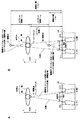
図1は、フォーカス距離、オフセット距離及び輻輳距離の説明図である。図1Aは、被写体のいる位置でフォーカス点及び輻輳点が一致している例を示す。
[Explanation of focus distance, offset distance and convergence distance]
FIG. 1 is an explanatory diagram of a focus distance, an offset distance, and a convergence distance. FIG. 1A shows an example in which the focus point and the convergence point coincide at the position where the subject is present.
立体映像撮像装置100は、人間の左右の目の幅に合わせた基線長(IAD:Inter Axial Distance)だけ隔てて配置される左右一対の撮像レンズを含む左レンズ光学系121Lと右レンズ光学系121Rを備える。立体映像撮像装置100に実装される左レンズ光学系121Lと右レンズ光学系121Rは、レンズの光軸が被写体に向けて交差するように斜めに設けられ、不図示のシフトレンズを用いて各光学系の輻輳点を手前又は奥行き方向に移動させている。
The stereoscopic
左レンズ光学系121Lと右レンズ光学系121Rは主従関係を持っており、主となる光学系の動作に従となる光学系の動作が連動する。本例では、左レンズ光学系121Lを主とし、右レンズ光学系121Rを従としている。そして、主となる左レンズ光学系121Lを被写体に向けてフォーカスを合わせている。なお、右レンズ光学系121Rを主とし、左レンズ光学系121Lを従とする運用としてもよい。
The left lens
立体映像撮像装置100は被写体の正面に位置しており、左レンズ光学系121Lと右レンズ光学系121Rは、一例として、被写体である人間の頭部にフォーカスを合わせている。以下の説明では、左レンズ光学系121Lの光軸方向であって、左レンズ光学系121Lの撮像レンズからフォーカス点F1までの距離を「フォーカス距離」と呼ぶ。同様に、左レンズ光学系121Lの光軸方向であって、左レンズ光学系121Lの撮像レンズから輻輳点A1までの距離を「輻輳距離」と呼ぶ。
The stereoscopic
左レンズ光学系121Lと右レンズ光学系121Rは、基線長の中点における垂線を線対称の軸線として、左レンズ光学系121Lの動作に従い、右レンズ光学系121Rが動作する。このため、右レンズ光学系121Rにおけるフォーカス距離と輻輳距離は、左レンズ光学系121Lにおける各距離に等しい。
In the left lens
図1Bは、輻輳点B1,B2を設定した例を示す。
各光学系は、被写体である人間の頭部にフォーカス点F2を定め、フォーカスを合わせている。ここで、フォーカス点F2を基準とした場合における輻輳点B1又は輻輳点B2までの距離を「オフセット距離」と呼ぶ。例えば、フォーカス点F2をオフセット距離の基準である±0mとした場合に、フォーカス点F2より撮影レンズから見て手前側を負のオフセット距離に設定し、フォーカス点F2より撮影レンズから見て奥側を正のオフセット距離に設定する。このため、オフセット距離が−1mで設定されると、被写体の1m手前に輻輳点B2が設定される。そして、フォーカス距離にオフセット距離(−1m)を加えることで、輻輳点B2における輻輳距離(−1m)が求まる。このとき、フォーカス距離>輻輳距離の関係を満たす。
FIG. 1B shows an example in which the convergence points B1 and B2 are set.
Each optical system determines a focus point F2 on the human head, which is the subject, and focuses. Here, the distance to the convergence point B1 or the convergence point B2 when the focus point F2 is used as a reference is referred to as an “offset distance”. For example, when the focus point F2 is set to ± 0 m which is the reference of the offset distance, the front side from the focus point F2 when viewed from the photographing lens is set to a negative offset distance, and the rear side from the focus point F2 as viewed from the photographing lens Set to a positive offset distance. For this reason, when the offset distance is set to −1 m, the convergence point B2 is set to 1 m before the subject. Then, by adding the offset distance (−1 m) to the focus distance, the convergence distance (−1 m) at the convergence point B2 is obtained. At this time, the relationship of focus distance> convergence distance is satisfied.
一方、オフセット距離が+1mで設定されると、被写体の1m奥に輻輳点B1が設定される。そして、フォーカス距離にオフセット距離(+1m)を加えることで、輻輳点B1における輻輳距離(+1m)が求まる。このとき、フォーカス距離<輻輳距離の関係を満たす。 On the other hand, when the offset distance is set at +1 m, the convergence point B1 is set 1 m behind the subject. Then, the convergence distance (+1 m) at the convergence point B1 is obtained by adding the offset distance (+1 m) to the focus distance. At this time, the relationship of focus distance <congestion distance is satisfied.
なお、図1Bでは主となる左レンズ光学系121Lの光軸上の距離を「オフセット距離」として定義した上で説明しているが、左レンズ光学系121Lと右レンズ光学系121Rの光軸の中心線(本例では、垂線)上に定義し直してもよい。そして、フォーカスを合わせた被写体が画面の奥にあることを強調したい場合は、フォーカス距離より短い距離に輻輳点を設定すればよい。一方、フォーカスを合わせた被写体を画面から浮かびあがらせたい場合は、フォーカス距離より長い距離に輻輳点を設定すればよい。
In FIG. 1B, the distance on the optical axis of the main left lens
[立体映像撮像装置の構成]
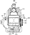
図2は、本発明の第1の実施の形態に係る立体映像撮像装置100の正面図を示す。
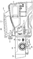
図3は、本発明の第1の実施の形態に係る立体映像撮像装置100の左側面図を示す。
立体映像撮像装置100は、本体部110とレンズ部120とを有する。
[Configuration of stereoscopic imaging device]
FIG. 2 shows a front view of the stereoscopic
FIG. 3 is a left side view of the stereoscopic
The stereoscopic
二眼レンズ式の立体映像撮像装置100は、左右のレンズを通してそれぞれ取り込んだ被写体の左右の像を、撮像素子で電気的な信号に変換し、A/D変換を行う。その後、HDV(High-Definition Video)方式などの所定の方式で圧縮符号化して、左右それぞれの半導体記録媒体に記録する。撮像素子には、例えば、CCD(Charge Coupled Device)イメージャやCMOS(Complementary Metal Oxide Semiconductor)センサ等が用いられる。
The binocular lens type stereoscopic
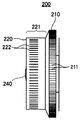
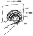
立体映像撮像装置100の側面には、ズーム、フォーカス、及びコンバージェンスの調整を行うための3つのリングで構成される調整リング200を備える。3つのリングは、互いに同軸となるように組み合わされ、かつ互いに独立して回動して操作することが可能である。そして、ズーム、フォーカス、及びコンバージェンスの調整を行うために、ズームリング210、フォーカスリング220、及びコンバージェンスリング230が設けられている。撮影者が所望の立体映像を撮像するためには、一般には交互に繰り返しフォーカスとコンバージェンスを調整することが多い。しかし、調整リング200の同軸でそれぞれ独立して回動可能であるフォーカス調整用のフォーカスリング220とコンバージェンス調整用のコンバージェンスリング230を用いるため、調整作業の効率を向上させることができる。
The side surface of the stereoscopic
本例の立体映像撮像装置100は、コンバージェンスリング230の中心部分に配され、フォーカスリング220及びコンバージェンスリング230の軸方向に突出する指示ボタン240を備える。指示ボタン240が撮影者によって押下されると、コンバージェンスリング230による輻輳距離の調整とは別に、制御回路312(後述する図6参照)に対して輻輳距離の調整を開始する指示を行う。指示ボタン240は、左右一対の撮像レンズの光軸が交わる輻輳点から撮像レンズまでの輻輳距離の調整を開始する指示を行う調整指示部として用いられる。
The stereoscopic
この他、本体部110には、外部機器に接続するために用いられる各種のインタフェース群、各種の操作ボタン群、ハンドル111、表示部113、不図示のバッテリアダプタ、メモリカードスロット等が設けられている。インタフェース群及びバッテリアダプタは主に本体部110の後部に設けられている。インタフェースとしては、例えば、デジタル映像及びデジタル音声の入出力、アナログ映像及びアナログ音声の入出力、制御用の入力、モニタ出力、ヘッドホン出力などがある。また、バッテリアダプタには、不図示のバッテリを着脱することが可能とされている。
In addition, the
操作部115、表示部113、及びメモリカードスロットは主に本体部110の側面に設けられている。操作部115には、例えば、電源ボタン、録画ボタン、再生ボタン、早送りボタン、戻りボタン、シャッタボタン、その他のボタンが含まれる。表示部113は撮像中の映像や記録映像、機能選択や設定操作を行うためのグラフィカル・ユーザ・インタフェース(GUI: Graphical User Interface)などの表示や、オフセット距離を設定する設定部として用いられたりする。そして、表示部113は、本体部110の側面において2軸の回り方向に回動自在に設けられている。メモリカードスロットは、半導体記録媒体であるメモリカードの着脱が可能とされ、このメモリカードに対してデジタル映像データの記録及び読み出しを行うことが可能である。
The
表示部113としては、例えば液晶ディスプレイや有機ELディスプレイ等が採用されており、撮影者が被写体を撮像しながら立体映像を確認するために3Dモニタとして用いることができる。そして、表示部113には、オートフォーカス又はマニュアルによるフォーカスの設定を区別して表示する。なお、表示部113は、主として動作する左レンズ光学系121Lによって撮像された左映像のみを表示したり、左映像を緑、右映像を赤とするアナグリフで表現する場合に、緑色の左映像を表示したりする。これらの映像は不図示のビューファインダによって表示するようにしてもよい。
As the
操作ボタン群の一部やハンドル111は、主に本体部110の上面に設けられている。ハンドル111は撮影者が立体映像撮像装置100を支持するために用いられる。ハンドル111の前部にはマイクロフォン119が取り付けられ、本体部110の内部には、CPU(Central Processing Unit)等の制御回路、左右の撮像素子、信号処理回路、エンコーダ回路などが収納されている。
A part of the operation button group and the
レンズ部120には、右レンズ光学系121Rと左レンズ光学系121Lが左右平行に設けられ、設定された輻輳角に応じて右レンズ光学系121Rと左レンズ光学系121Lの光軸が傾けられる。左レンズ光学系121Lが動作すると、右レンズ光学系121Rは、ズーム、フォーカス、及びコンバージェンスの調整を左レンズ光学系121Lの動作に同期して行う。
The
また、レンズ部120の先端部には、右レンズ光学系121Rと左レンズ光学系121Lに入射する光の波長を制限するレンズフィルタ123が設けられている。また、右レンズ光学系121Rと左レンズ光学系121Lの撮像レンズを様々な目的で保護するレンズフード125が設けられている。
A
レンズ部120の側面には、調整リング200の他、撮影者の手によって把持されるグリップ部127が設けられ、グリップ部127には広角/望遠スイッチ128が設けられている。また、レンズ部120の側面には、右レンズ光学系121R及び左レンズ光学系121Lに入る光の量を減少させるよう調整する減光フィルタボタン129が設けられている。さらに、露出を調整することで撮像する画像の明るさを調整するアイリスダイヤル130等も設けられている。
In addition to the
[調整リングの構成]
次に、調整リング200の構成について、図4と図5を参照して説明する。
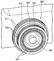
図4は、調整リング200の斜視図を示す。
図5は、調整リング200の側面図を示す。
[Adjustment ring configuration]
Next, the configuration of the
FIG. 4 shows a perspective view of the
FIG. 5 shows a side view of the
調整リング200は、ズームを調整するためのズームリング210、フォーカスを調整するためのフォーカスリング220、及びコンバージェンスを調整するためのコンバージェンスリング230で構成される。ズームリング210、フォーカスリング220、及びコンバージェンスリング230はそれぞれ入れ子構造で組み合わされて、互いに独立して正・逆方向に同軸で回動自在に構成されている。
The
ズームリング210は、調整リング200において最も外周側に位置する回動部である。
フォーカスリング220は、回動されることにより光学系のフォーカスを合わせて、フォーカス点を調整するフォーカス調整部として用いられる。
コンバージェンスリング230は、外径が異なるフォーカスリング220と同軸に入れ子構造で組み合わされ、フォーカスリング220とは別に回動されることにより、輻輳点を調整する。そして、コンバージェンスリング230は、ズームリング210の内側で回動自在であり、さらにフォーカスリング220の内側で回動自在である。したがって、ズームリング210、フォーカスリング220、コンバージェンスリング230の外径は、ズームリング210、フォーカスリング220、コンバージェンスリング230の順に小さくなる。このため、撮影者は操作しているリングの位置関係を容易に知ることができ、操作性の向上が期待される。
The
The
The
ズームリング210の外周面には滑り止め用のスリット211が設けられている。また、フォーカスリング220はズームリング210より軸方向において突出した部分221を有する。この突出した部分221の外周面に滑り止め用のスリット222が設けられている。一方、フォーカスリング220の内側に回動自在に配置されたコンバージェンスリング230の先端位置はフォーカスリング220の先端位置と一致若しくは略一致させてある。コンバージェンスリング230の先端部分はすり鉢状に凹ませてあり、この凹んだ部分の内周面(のり面)に滑り止め用のスリット231が設けられている。
A
上述したように調整リング200は、ズームリング210を調整リング200において最も外周側に配置する構成としてある。さらに、フォーカスリング220をズームリング210の内側に配置し、コンバージェンスリング230をフォーカスリング220の内側に配置する構成としてある。また、ズームリング210からフォーカスリング220を突出させている。
As described above, the
ただし、このような構成に限らず、ズームリング210を調整リング200において最も内周側に配置し、その外周に、フォーカスリング220、コンバージェンスリング230の順に配置してもよい。あるいは、コンバージェンスリング230、フォーカスリング220の順に配置してもよい。また、調整リング200は撮影者が操作しやすい場所であれば、本体部110の側面以外の場所に設けてもよい。さらに、フォーカスリング220からコンバージェンスリング230を突出させ、コンバージェンスリング230の突出した部分の外周面に滑り止めに用いるスリットを設けてもよい。
However, the present invention is not limited to such a configuration, and the
[ズーム、フォーカス、及びコンバージェンスの調整回路]
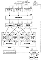
図6は、ズーム、フォーカス、及びコンバージェンスの調整回路の構成例を示す。
[Zoom, focus, and convergence adjustment circuits]
FIG. 6 shows a configuration example of an adjustment circuit for zoom, focus, and convergence.
立体映像撮像装置100は、調整リング200のズームリング210、フォーカスリング220、及びコンバージェンスリング230にそれぞれ対応する以下の回路を有する。すなわち、ロータリーエンコーダ301,302,303、光学系制御回路304、ズーム駆動回路305、フォーカス駆動回路306、コンバージェンス駆動回路307、である。さらに、左光学系ズームアクチュエータ308L、左光学系フォーカスアクチュエータ309L、左光学系コンバージェンスアクチュエータ310Lがある。同様に、右光学系ズームアクチュエータ308R、右光学系フォーカスアクチュエータ309R、右光学系コンバージェンスアクチュエータ310Rがある。フォーカスリング220は、右レンズ光学系121Rと左レンズ光学系121Lのフォーカス点の位置(フォーカス距離)を調整するフォーカス調整部として用いられる。
The stereoscopic
独立して回動操作されるズームリング210、フォーカスリング220、及びコンバージェンスリング230によって出力されるそれぞれの回動情報は、各リングに対応して設けられたロータリーエンコーダ301,302,303によって検出される。ロータリーエンコーダ301,302,303の検出情報はCPUなどの光学系制御回路304に伝送される。光学系制御回路304はズーム調整に対応するロータリーエンコーダ301の検出情報に基づいて、ズーム調整に関する所定の演算処理を実行して制御量を求め、制御量に応じた制御情報をズーム駆動回路305に供給する。
The respective rotation information output by the
ズーム駆動回路305は、制御情報に基づいて左光学系ズームアクチュエータ308Lと右光学系ズームアクチュエータ308Rを駆動する。これにより右レンズ光学系121Rと左レンズ光学系121Lのズームの調整が行われる。また、光学系制御回路304はフォーカス調整に対応するロータリーエンコーダ302の検出情報に基づいてフォーカス調整に関する所定の演算処理を実行して制御量を求め、制御量に応じた制御情報をフォーカス駆動回路306に供給する。
The
フォーカス駆動回路306は、制御情報に基づいて左光学系フォーカスアクチュエータ309L及び右光学系フォーカスアクチュエータ309Rを駆動する。これにより右レンズ光学系121Rと左レンズ光学系121Lのフォーカスの調整が行われる。
The
さらに、光学系制御回路304は、コンバージェンス調整に対応するロータリーエンコーダ303の検出情報に基づいてコンバージェンス調整に関する所定の演算処理を実行して制御量を求める。そして、その制御量に応じた制御情報をコンバージェンス駆動回路307に供給する。コンバージェンス駆動回路307は、制御情報に基づいて左光学系コンバージェンスアクチュエータ310L及び右光学系コンバージェンスアクチュエータ310Rを駆動する。これにより右レンズ光学系121Rと左レンズ光学系121Lのコンバージェンスの調整が行われる。
Furthermore, the optical
また、立体映像撮像装置100は、左レンズ光学系121Lから受け取る情報より、基線長及びフォーカス点に基づいて、撮像レンズからフォーカス点までのフォーカス距離を検出するフォーカス距離検出部としてのフォーカスポジションセンサ311を備える。フォーカスポジションセンサ311は、三角測量を応用して、予め判明している基線長及びフォーカス点よりフォーカス距離を求めることができる。
In addition, the stereoscopic
また、立体映像撮像装置100は、フォーカス距離に基づいて輻輳距離を求める制御回路312を備える。
制御回路312は、輻輳距離の調整を開始する指示を行う指示ボタン240が押下されると、撮像レンズから輻輳点までの輻輳距離を調整する制御部として用いられる。このとき、制御回路312は、フォーカスリング220によってフォーカス点が調整された後、撮像レンズの光軸方向におけるフォーカス点から設定しようとする輻輳点までの距離をオフセット距離とする。そして、撮像レンズからフォーカス点までのフォーカス距離にオフセット距離を加えて、撮像レンズから輻輳点までの輻輳距離を調整する。
In addition, the stereoscopic
The
ここで、図1Bを参照して説明したように、制御回路312は、フォーカス点より奥に輻輳点が位置するように調整する場合には、正のオフセット距離をフォーカス距離に加える。一方、フォーカス点より手前に輻輳点が位置するように調整する場合には、負のオフセット距離をフォーカス距離に加える。これにより、撮影者が指示ボタン240を押下するだけでフォーカス距離に合わせた輻輳距離の調整を自動的に行うことが可能となる。
Here, as described with reference to FIG. 1B, the
このように立体映像撮像装置100は、輻輳距離の自動調整を実行する指示ボタン240と、輻輳点とフォーカス点との位置関係を設定するメニューを提示する。このメニューには、表示部113に表示されるGUIが含まれる場合があるが、本体部110に取付けた操作ボタン等によりメニューの機能を実現してもよい。このメニューを用いると、撮影者が輻輳点とフォーカス点の所望の位置関係(距離)をオフセット距離として事前に設定しておくことができる。そして、撮影時にはフォーカスを合わせた後、指示ボタン240を押す操作だけで立体映像撮像装置100が自動的に輻輳点位置を調整する。このため、撮影者が手動で行う輻輳点やフォーカス点の調整作業を簡略化し、容易に所望の3D映像を得ることを可能とする。
As described above, the stereoscopic
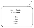
図7は、表示部113に表示されるオフセット距離を設定するための設定メニューの表示例を示す。
制御回路312は、操作部115の入力操作がなされると、撮影者がオフセット距離の値を設定するために用いるメニュー画面を表示部113に表示する。撮影者は、操作部115の操作入力により、コンバージェンス距離の算出のために用いられるオフセット距離を、「コンバージェンスオフセット距離」として事前に設定することができる。このため、立体映像の撮像時には、指示ボタン240が押下されると、立体映像撮像装置100は、設定されたオフセット距離に合わせて輻輳距離を調整することができる。
FIG. 7 shows a display example of a setting menu for setting the offset distance displayed on the
When the input operation of the
[選択操作の例]
ここで選択操作の例を説明する。
始めに、撮影者は、表示部113に表示され、オフセット距離を設定するためのメニュー画面からオフセット距離をどの値にするか選択する。
[Example of selection operation]
Here, an example of the selection operation will be described.
First, the photographer selects what value the offset distance is to be displayed from the menu screen displayed on the
撮影時には、被写体にフォーカスを合わせた後、制御回路312は、選択されたオフセット距離に基づいて、フォーカスポジションセンサ311から取得したフォーカス距離に基づいて輻輳角を求める。そして、制御回路312は、コンバージェンス駆動回路307に対して左レンズ光学系121Lと右レンズ光学系121Rに含まれる撮像レンズの光軸を変えて、輻輳点に合わせた輻輳角を設定する。
At the time of shooting, after focusing on the subject, the
例えば、輻輳距離は次のように求められる。
表示部113のメニュー画面より操作部115を介して設定されたオフセット距離が+1m、フォーカス距離が3mの場合、輻輳距離は4m=3m+1mとする。このとき、左レンズ光学系121Lと右レンズ光学系121Rからそれぞれ半径4mの円弧の交点を求める。次に、制御回路312は、左レンズ光学系121Lと右レンズ光学系121Rから円弧の交点までの光軸の角度(輻輳角θ)をテーブル(または計算)により求める。このテーブルには、予めフォーカス距離に対する輻輳角の関係が記憶されている。このため、制御回路312は、フォーカスポジションセンサ311によって求められたフォーカス距離に基づいて、テーブルから輻輳角を読出す。そして、制御回路312は、この輻輳角に合わせて輻輳点が移動するようにコンバージェンス駆動回路307にコンバージェンスを調整する指示を行う。これにより、レンズ群の一部(例えば、シフトレンズ)は、撮影レンズの光軸の直交面、水平方向又は左右方向に駆動され、輻輳角が所定値θに設定される。
For example, the convergence distance is obtained as follows.
When the offset distance set via the
その後、撮影者は、表示部113に表示される映像を見ながら立体撮影の効果を確認する。ここで、意図した立体撮影が行えていないようであれば、オフセット距離を再度設定し直す。表示部113には、立体映像を表示可能な3Dビューファインダ又は3Dモニタが用いられているため、撮影者はリアルタイムで立体撮影の効果を確認できる。ただし、立体映像は、撮影後に不図示のHDD等から読み出し、再生した映像データに基づいて確認することもできる。
Thereafter, the photographer confirms the effect of the stereoscopic shooting while viewing the video displayed on the
次に、調整リング200の操作例について、図8〜図10を参照して説明する。
図8は、ズーム調整時の操作例を示す。
撮影者は、ズーム調整時にズームリング210の外周面に指を当ててズームリング210を回動操作する。この操作によって、ロータリーエンコーダ301で回動情報が検出され、ズームの調整を行うことかできる。
Next, an operation example of the
FIG. 8 shows an operation example during zoom adjustment.
The photographer rotates the
図9は、フォーカス調整時の操作例を示す。
撮影者は、フォーカス調整時にフォーカスリング220の突出した部分221の外周面に指を当ててフォーカスリング220を回動操作する。この操作によって、ロータリーエンコーダ302で回動情報が検出され、フォーカスの調整を行うことかできる。
FIG. 9 shows an operation example during focus adjustment.
The photographer rotates the
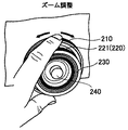
図10は、コンバージェンス調整時の操作例を示す。
撮影者は、コンバージェンス調整時にコンバージェンスリング230の先端部分のすり鉢状に凹んだ部分の内周面に指を当ててコンバージェンスリング230を回動操作する。この操作によって、ロータリーエンコーダ303で回動情報が検出され、コンバージェンス調整を行うことができる。
FIG. 10 shows an example of operation during convergence adjustment.
The photographer rotates the
ズームリング210、フォーカスリング220、及びコンバージェンスリング230は全て同軸に組み合わせた調整リング200として一体化されている。このため、撮影者は僅かに手を移動させるだけでズーム、フォーカス、コンバージェンス間で調整対象をスムーズに変更することができる。また、ズームリング210、フォーカスリング220、及びコンバージェンスリング230は全て同軸で回動されるので、全て同様な感覚での操作が可能である。したがって、調整対象を変更した直後から速やかに他の調整を開始することができる。特に、フォーカスとコンバージェンスの調整のように交互にかつ繰り返し行われることの多い調整作業において効率の向上を期待できる。
The
このようにズームリング210、フォーカスリング220、及びコンバージェンスリング230を全て同軸的に組み合わせて調整リング200として一体化してある。これにより、撮影者は僅かに手を移動させるだけでズーム、フォーカス、コンバージェンス間で調整対象をスムーズに変更することができる。また、ズームリング210、フォーカスリング220、及びコンバージェンスリング230は全て同軸で回動され、接触しないときには設定値が変わらない。このため、撮影者が調整後に手を離して、再び調整を行う際には、以前設定した値から調整を再開することができる。特に、フォーカスとコンバージェンスの調整のように交互にかつ繰り返し行われることの多い調整作業において効率の向上を期待できる。また、ズーム調整によってフォーカス調整が必要になる場合には、ズーム調整を含めて調整作業の効率化を図れる。
Thus, the
以上説明した本実施形態に係る立体映像撮像装置100によれば、指示ボタン240を押下するだけでオフセット距離に合わせた輻輳距離を容易に設定できる。このため、従来のように手動操作でフォーカス距離と輻輳距離を別々に設定する場合に比べて、輻輳距離の変更が完了するまでの時間を大幅に短縮することができる。また、一旦設定したオフセット距離は変わらないため、指示ボタン240を押下するだけでオフセット距離が一定である立体映像を安定して撮像することができ、撮影途中でオフセット距離が変わることによる立体映像の違和感が生じない。このため、高品質な立体映像を撮影する場合における立体映像撮像装置100の操作性を容易とすることができる。
According to the stereoscopic
また、指示ボタン240は、調整リング200の中心部に軸方向に突出した状態で配置してある。このため、普段の操作では撮影者が指示ボタン240に誤って触れる可能性がなく、意図しない立体映像を撮影することがない。
Further, the
また、オフセット距離は事前にユーザによって任意の値を設定することが可能である。このため、オフセット距離の変更が容易であり、輻輳距離が少しずつ異なる同じ被写体を撮影する際に操作の手間を減らすことができる。 The offset distance can be set to an arbitrary value by the user in advance. For this reason, it is easy to change the offset distance, and it is possible to reduce the labor of the operation when photographing the same subject with slightly different convergence distances.
<2.第2の実施の形態>
[輻輳距離を自動追従する例]
次に、本発明の第2の実施の形態について、図11を参照して説明する。本実施の形態では、立体映像を撮像中にオートフォーカス等によってフォーカス距離が変わる場合であっても、このフォーカス距離の変化に輻輳距離を自動的に追従して変えるようにした立体映像撮像装置100に適用した例について説明する。以下の説明において、既に第1の実施の形態で説明した図1〜図4に対応する部分には同一符号を付し、詳細な説明を省略する。
<2. Second Embodiment>
[Example of automatically tracking the convergence distance]
Next, a second embodiment of the present invention will be described with reference to FIG. In the present embodiment, even when the focus distance changes due to autofocus or the like during imaging of a stereoscopic video, the stereoscopic
図11は、自動追従するオフセット距離を設定するための設定メニューの表示例を示す。
制御回路312は、フォーカスリング220によって調整されるフォーカス点に対して、自動的に輻輳点を追従させて輻輳距離を調整するか否かを選択させるメニュー画面を表示部113に表示する。撮影者が自動追従をオンに設定すると、設定した時点以降において、フォーカス点が動的に変動しても、フォーカスポジションセンサ311が自動的にフォーカス距離を求める。そして、制御回路312は、事前に設定したオフセット距離を保持するようにフォーカス距離に基づいて輻輳点を自動的に追従させて輻輳距離を調整する。
FIG. 11 shows a display example of a setting menu for setting an offset distance for automatic tracking.
The
以上説明した第2の実施の形態に係る立体映像撮像装置100によれば、輻輳点の自動追従をオンすることにより、撮影者はオートフォーカス等を用いて動的にフォーカス点を変える場合であっても、輻輳点が自動的に変化し、輻輳距離が調整される。このため、動きのある被写体や、奥行き方向に移動する被写体等を撮影する場合に、フォーカスを合わせるだけで、意図した輻輳距離による立体映像の撮影が容易となる。このように、撮影者は輻輳点を設定するための複雑な操作が不要であり、撮影に集中することができるため、撮影した立体映像の品質を高めることができる。
According to the stereoscopic
<3.変形例>
なお、この輻輳点の自動追従について特にメニュー画面を設けることなく、初めから自動追従をオンに設定しておいてもよい。これにより、撮影者がマニュアル又はオートフォーカスによりフォーカス点を動かしても、輻輳点の設定を意識することなく良好な立体映像を撮像できる。
<3. Modification>
Note that the automatic tracking of the convergence point may be turned on from the beginning without providing a menu screen. As a result, even when the photographer moves the focus point manually or by auto-focusing, a good stereoscopic image can be captured without being aware of the setting of the convergence point.
また、上述した第1及び第2の実施の形態では、フォーカス調整部としてフォーカスリング220を用い、コンバージェンス調整部としてコンバージェンスリング230を用い、調整指示部として指示ボタン240を用いた。しかし、フォーカス調整部、コンバージェンス調整部及び調整指示部としてはリングに限らず、スライドスイッチや各種のスイッチ機構を用いてもよい。また、表示部113にGUI表示させたメニューにより各種の値を調整するようにしてもよい。
In the first and second embodiments described above, the
また、上述した第1及び第2の実施の形態では、二眼レンズ式の立体映像撮像装置100に適用した例を説明したが、従来のように、2台のカメラを用いて立体映像を生成する撮像システムに用いることも可能である。
In the first and second embodiments described above, the example applied to the binocular lens type stereoscopic
また、上述した実施の形態例における一連の処理は、ハードウェアにより実行することができるが、ソフトウェアにより実行させることもできる。一連の処理をソフトウェアにより実行させる場合には、そのソフトウェアを構成するプログラムが専用のハードウェアに組み込まれているコンピュータ、または、各種の機能を実行するためのプログラムをインストールしたコンピュータにより、実行可能である。例えば汎用のパーソナルコンピュータなどに所望のソフトウェアを構成するプログラムをインストールして実行させればよい。 The series of processes in the above-described embodiment can be executed by hardware, but can also be executed by software. When a series of processing is executed by software, it can be executed by a computer in which a program constituting the software is incorporated in dedicated hardware or a computer in which programs for executing various functions are installed. is there. For example, what is necessary is just to install and run the program which comprises desired software in a general purpose personal computer.
また、上述した実施の形態の機能を実現するソフトウェアのプログラムコードを記録した記録媒体を、システムあるいは装置に供給してもよい。また、そのシステムあるいは装置のコンピュータ(またはCPU等の制御装置)が記録媒体に格納されたプログラムコードを読み出し実行することによっても、機能が実現されることは言うまでもない。 Further, a recording medium on which a program code of software that realizes the functions of the above-described embodiments may be supplied to the system or apparatus. It goes without saying that the function is also realized by a computer (or a control device such as a CPU) of the system or apparatus reading and executing the program code stored in the recording medium.
この場合のプログラムコードを供給するための記録媒体としては、例えば、フレキシブルディスク、ハードディスク、光ディスク、光磁気ディスク、CD−ROM、CD−R、磁気テープ、不揮発性のメモリカード、ROMなどを用いることができる。 As a recording medium for supplying the program code in this case, for example, a flexible disk, a hard disk, an optical disk, a magneto-optical disk, a CD-ROM, a CD-R, a magnetic tape, a nonvolatile memory card, a ROM, or the like is used. Can do.
また、コンピュータが読み出したプログラムコードを実行することにより、上述した実施の形態の機能が実現される。加えて、そのプログラムコードの指示に基づき、コンピュータ上で稼動しているOSなどが実際の処理の一部又は全部を行う。その処理によって上述した実施の形態の機能が実現される場合も含まれる。 Further, the functions of the above-described embodiment are realized by executing the program code read by the computer. In addition, based on the instruction of the program code, the OS running on the computer performs part or all of the actual processing. The case where the functions of the above-described embodiment are realized by the processing is also included.
また、本開示は上述した実施の形態に限られるものではなく、特許請求の範囲に記載した本開示の要旨を逸脱しない限りその他種々の応用例、変形例を取り得ることは勿論である。 Further, the present disclosure is not limited to the above-described embodiment, and various other application examples and modifications may be taken without departing from the gist of the present disclosure described in the claims.
なお、本開示は以下のような構成も取ることができる。
(1) 所定の基線長を隔てて配置される左右一対の撮像レンズを含む光学系と、
前記光学系のフォーカスを合わせて、フォーカス点を調整するフォーカス調整部と、
前記フォーカス調整部によってフォーカス点が調整された後、前記撮像レンズの光軸方向における前記フォーカス点から設定しようとする輻輳点までの距離をオフセット距離として、前記撮像レンズから前記フォーカス点までのフォーカス距離に前記オフセット距離を加えて、前記撮像レンズから前記輻輳点までの輻輳距離を調整する制御部と、を備える
立体映像撮像装置。
(2) 前記制御部は、前記フォーカス点より奥に前記輻輳点が位置するように調整する場合には、正の前記オフセット距離を前記フォーカス距離に加え、前記フォーカス点より手前に前記輻輳点が位置するように調整する場合には、負の前記オフセット距離を前記フォーカス距離に加える
前記(1)記載の立体映像撮像装置。
(3) さらに、前記オフセット距離を設定する設定部と、
前記輻輳距離の調整を開始する指示を行う調整指示部と、
前記基線長及び前記フォーカス点に基づいて、前記撮像レンズから前記フォーカス点までのフォーカス距離を検出するフォーカス距離検出部と、を備える
前記(1)又は(2)記載の立体映像撮像装置。
(4) 前記フォーカス調整部は、回動されることにより前記光学系のフォーカスを調整するフォーカスリングであり、
外径が異なる前記フォーカスリングと同軸に入れ子構造で組み合わされ、前記フォーカスリングとは別に回動されることにより、前記輻輳距離の調整を行うコンバージェンスリングを備え、
前記調整指示部は、前記フォーカスリング及び前記コンバージェンスリングの軸方向に突出し、押下されることによって、前記コンバージェンスリングによる前記輻輳距離の調整とは別に、前記制御部に対して前記輻輳距離の調整を開始する指示を行うボタンである
前記(1)〜(3)のいずれかに記載の立体映像撮像装置。
(5) 前記制御部は、前記オフセット距離の値を設定するメニュー画面を表示部に表示する
前記(1)〜(4)のいずれかに記載の立体映像撮像装置。
(6) 前記制御部は、前記フォーカス調整部によって調整されるフォーカスに追従して、前記制御部が前記輻輳距離を調整するか否かを選択させるメニュー画面を表示部に表示する
前記(1)〜(4)のいずれかに記載の立体映像撮像装置。
(7) 所定の基線長を隔てて配置される左右一対の撮像レンズを含む光学系のフォーカスを合わせて、フォーカス点を調整することと、
前記撮像レンズの光軸方向における前記フォーカス点から設定しようとする輻輳点までの距離をオフセット距離として、前記撮像レンズから前記フォーカス点までのフォーカス距離に前記オフセット距離を加えて、前記撮像レンズから前記輻輳点までの輻輳距離を調整することと、を含む
輻輳距離調整方法。
(8) 所定の基線長を隔てて配置される左右一対の撮像レンズを含む光学系のフォーカスを合わせて、フォーカス点を調整する手順、
前記撮像レンズの光軸方向における前記フォーカス点から設定しようとする輻輳点までの距離をオフセット距離として、前記撮像レンズから前記フォーカス点までのフォーカス距離に前記オフセット距離を加えて、前記撮像レンズから前記輻輳点までの輻輳距離を調整する手順とを
コンピュータに実行させるプログラム。
In addition, this indication can also take the following structures.
(1) an optical system including a pair of left and right imaging lenses arranged with a predetermined baseline length therebetween;
A focus adjustment unit for adjusting a focus point by adjusting the focus of the optical system;
After the focus point is adjusted by the focus adjustment unit, the distance from the focus point to the convergence point to be set in the optical axis direction of the imaging lens is an offset distance, and the focus distance from the imaging lens to the focus point And a control unit that adjusts a convergence distance from the imaging lens to the convergence point by adding the offset distance to the stereoscopic video imaging apparatus.
(2) When adjusting the convergence point so that the convergence point is located behind the focus point, the control unit adds the positive offset distance to the focus distance, and the convergence point is located before the focus point. In the case of adjusting to be positioned, the negative offset distance is added to the focus distance. The stereoscopic video imaging apparatus according to (1).
(3) Furthermore, a setting unit for setting the offset distance;
An adjustment instruction unit for giving an instruction to start adjustment of the convergence distance;
A stereoscopic image capturing apparatus according to (1) or (2), further comprising: a focus distance detecting unit that detects a focus distance from the imaging lens to the focus point based on the base line length and the focus point.
(4) The focus adjustment unit is a focus ring that adjusts the focus of the optical system by being rotated,
It is combined with the focus ring having a different outer diameter coaxially in a nested structure, and is provided with a convergence ring that adjusts the convergence distance by being rotated separately from the focus ring,
The adjustment instruction unit protrudes in the axial direction of the focus ring and the convergence ring, and is pressed to adjust the convergence distance to the control unit separately from the adjustment of the convergence distance by the convergence ring. The stereoscopic video imaging apparatus according to any one of (1) to (3), wherein the stereoscopic video imaging apparatus is a button for performing an instruction to start.
(5) The stereoscopic video imaging device according to any one of (1) to (4), wherein the control unit displays a menu screen for setting a value of the offset distance on a display unit.
(6) The control unit displays on the display unit a menu screen that allows the control unit to select whether to adjust the convergence distance following the focus adjusted by the focus adjustment unit. The three-dimensional imaging device according to any one of to (4).
(7) adjusting a focus point by adjusting a focus of an optical system including a pair of left and right imaging lenses arranged with a predetermined baseline length;
The distance from the focus point in the optical axis direction of the imaging lens to the convergence point to be set is set as an offset distance, and the offset distance is added to the focus distance from the imaging lens to the focus point. Adjusting a convergence distance to a point of convergence, and a method for adjusting a convergence distance.
(8) A procedure for adjusting a focus point by adjusting a focus of an optical system including a pair of left and right imaging lenses arranged with a predetermined baseline length therebetween,
The distance from the focus point in the optical axis direction of the imaging lens to the convergence point to be set is set as an offset distance, and the offset distance is added to the focus distance from the imaging lens to the focus point. A program that causes a computer to execute a procedure for adjusting the convergence distance to the point of convergence.
100…立体映像撮像装置、110…本体部、113…表示部、115…操作部、120…レンズ部、121L…左レンズ光学系、121R…右レンズ光学系、123…レンズフィルタ、125…レンズフード、200…調整リング、210…ズームリング、220…フォーカスリング、230…コンバージェンスリング、240…設定ボタン、311…フォーカスポジションセンサ、312…制御回路
DESCRIPTION OF
Claims (8)
前記光学系のフォーカスを合わせて、フォーカス点を調整するフォーカス調整部と、
前記フォーカス調整部によってフォーカス点が調整された後、前記撮像レンズの光軸方向における前記フォーカス点から設定しようとする輻輳点までの距離をオフセット距離として、前記撮像レンズから前記フォーカス点までのフォーカス距離に前記オフセット距離を加えて、前記撮像レンズから前記輻輳点までの輻輳距離を調整する制御部と、を備える
立体映像撮像装置。 An optical system including a pair of left and right imaging lenses arranged with a predetermined baseline length therebetween;
A focus adjustment unit for adjusting a focus point by adjusting the focus of the optical system;
After the focus point is adjusted by the focus adjustment unit, the distance from the focus point to the convergence point to be set in the optical axis direction of the imaging lens is an offset distance, and the focus distance from the imaging lens to the focus point And a control unit that adjusts a convergence distance from the imaging lens to the convergence point by adding the offset distance to the stereoscopic video imaging apparatus.
請求項1記載の立体映像撮像装置。 When adjusting the convergence point so that the convergence point is located behind the focus point, the control unit adds the positive offset distance to the focus distance so that the convergence point is located before the focus point. The stereoscopic video imaging apparatus according to claim 1, wherein the negative offset distance is added to the focus distance.
前記輻輳距離の調整を開始する指示を行う調整指示部と、
前記基線長及び前記フォーカス点に基づいて、前記撮像レンズから前記フォーカス点までのフォーカス距離を検出するフォーカス距離検出部と、を備える
請求項2記載の立体映像撮像装置。 A setting unit for setting the offset distance;
An adjustment instruction unit for giving an instruction to start adjustment of the convergence distance;
The stereoscopic video imaging apparatus according to claim 2, further comprising: a focus distance detection unit that detects a focus distance from the imaging lens to the focus point based on the base line length and the focus point.
外径が異なる前記フォーカスリングと同軸に入れ子構造で組み合わされ、前記フォーカスリングとは別に回動されることにより、前記輻輳距離の調整を行うコンバージェンスリングを備え、
前記調整指示部は、前記フォーカスリング及び前記コンバージェンスリングの軸方向に突出し、押下されることによって、前記コンバージェンスリングによる前記輻輳距離の調整とは別に、前記制御部に対して前記輻輳距離の調整を開始する指示を行うボタンである
請求項3記載の立体映像撮像装置。 The focus adjustment unit is a focus ring that adjusts the focus of the optical system by being rotated;
It is combined with the focus ring having a different outer diameter coaxially in a nested structure, and is provided with a convergence ring that adjusts the convergence distance by being rotated separately from the focus ring,
The adjustment instruction unit protrudes in the axial direction of the focus ring and the convergence ring, and is pressed to adjust the convergence distance to the control unit separately from the adjustment of the convergence distance by the convergence ring. The stereoscopic video imaging apparatus according to claim 3, wherein the button is a button for giving an instruction to start.
請求項4記載の立体映像撮像装置。 The stereoscopic video imaging apparatus according to claim 4, wherein the control unit displays a menu screen for setting the value of the offset distance on a display unit.
請求項5記載の立体映像撮像装置。 The stereoscopic video according to claim 5, wherein the control unit displays a menu screen that allows the control unit to select whether or not to adjust the convergence distance following the focus adjusted by the focus adjustment unit. Imaging device.
前記撮像レンズの光軸方向における前記フォーカス点から設定しようとする輻輳点までの距離をオフセット距離として、前記撮像レンズから前記フォーカス点までのフォーカス距離に前記オフセット距離を加えて、前記撮像レンズから前記輻輳点までの輻輳距離を調整することと、を含む
輻輳距離調整方法。 Adjusting the focus point by adjusting the focus of an optical system including a pair of left and right imaging lenses arranged with a predetermined baseline length; and
The distance from the focus point in the optical axis direction of the imaging lens to the convergence point to be set is set as an offset distance, and the offset distance is added to the focus distance from the imaging lens to the focus point. Adjusting a convergence distance to a point of convergence, and a method for adjusting a convergence distance.
前記撮像レンズの光軸方向における前記フォーカス点から設定しようとする輻輳点までの距離をオフセット距離として、前記撮像レンズから前記フォーカス点までのフォーカス距離に前記オフセット距離を加えて、前記撮像レンズから前記輻輳点までの輻輳距離を調整する手順とを
コンピュータに実行させるプログラム。 A procedure for adjusting the focus point by adjusting the focus of an optical system including a pair of left and right imaging lenses arranged with a predetermined baseline length;
The distance from the focus point in the optical axis direction of the imaging lens to the convergence point to be set is set as an offset distance, and the offset distance is added to the focus distance from the imaging lens to the focus point. A program that causes a computer to execute a procedure for adjusting the convergence distance to the point of convergence.
Priority Applications (7)
| Application Number | Priority Date | Filing Date | Title |
|---|---|---|---|
| JP2011085564A JP2012220679A (en) | 2011-04-07 | 2011-04-07 | Stereoscopic video imaging apparatus, convergence distance adjustment method, and program |
| KR1020137023911A KR20140020901A (en) | 2011-04-07 | 2012-03-15 | Stereoscopic video imaging apparatus, convergence distance adjustment method, and program for convergence distance adjustment method |
| CN2012800163243A CN103477280A (en) | 2011-04-07 | 2012-03-15 | Stereoscopic video imaging apparatus, convergence distance adjustment method, and program for convergence distance adjustment method |
| US14/008,650 US20140240465A1 (en) | 2011-04-07 | 2012-03-15 | Three-dimensional image pickup apparatus, convergence distance adjustment method, and program |
| PCT/JP2012/001815 WO2012137423A1 (en) | 2011-04-07 | 2012-03-15 | Stereoscopic video imaging apparatus, convergence distance adjustment method, and program for convergence distance adjustment method |
| BR112013025253A BR112013025253A2 (en) | 2011-04-07 | 2012-03-15 | three-dimensional imaging apparatus, convergence distance adjustment method, and program |
| TW101110841A TWI457691B (en) | 2011-04-07 | 2012-03-28 | Dimensional image camera, convergence distance adjustment method and program |
Applications Claiming Priority (1)
| Application Number | Priority Date | Filing Date | Title |
|---|---|---|---|
| JP2011085564A JP2012220679A (en) | 2011-04-07 | 2011-04-07 | Stereoscopic video imaging apparatus, convergence distance adjustment method, and program |
Publications (2)
| Publication Number | Publication Date |
|---|---|
| JP2012220679A true JP2012220679A (en) | 2012-11-12 |
| JP2012220679A5 JP2012220679A5 (en) | 2014-04-17 |
Family
ID=46968839
Family Applications (1)
| Application Number | Title | Priority Date | Filing Date |
|---|---|---|---|
| JP2011085564A Pending JP2012220679A (en) | 2011-04-07 | 2011-04-07 | Stereoscopic video imaging apparatus, convergence distance adjustment method, and program |
Country Status (7)
| Country | Link |
|---|---|
| US (1) | US20140240465A1 (en) |
| JP (1) | JP2012220679A (en) |
| KR (1) | KR20140020901A (en) |
| CN (1) | CN103477280A (en) |
| BR (1) | BR112013025253A2 (en) |
| TW (1) | TWI457691B (en) |
| WO (1) | WO2012137423A1 (en) |
Cited By (2)
| Publication number | Priority date | Publication date | Assignee | Title |
|---|---|---|---|---|
| JP2014153471A (en) * | 2013-02-06 | 2014-08-25 | Canon Inc | Stereoscopic photography system |
| TWI561908B (en) * | 2015-03-27 | 2016-12-11 | Vivotek Inc | Auto focus method and apparatus using the same method |
Families Citing this family (4)
| Publication number | Priority date | Publication date | Assignee | Title |
|---|---|---|---|---|
| JPWO2012023168A1 (en) * | 2010-08-19 | 2013-10-28 | パナソニック株式会社 | Stereoscopic imaging device and stereoscopic imaging method |
| US9544574B2 (en) * | 2013-12-06 | 2017-01-10 | Google Inc. | Selecting camera pairs for stereoscopic imaging |
| WO2017218834A1 (en) | 2016-06-17 | 2017-12-21 | Kerstein Dustin | System and method for capturing and viewing panoramic images having motion parralax depth perception without images stitching |
| JP7023699B2 (en) * | 2017-12-14 | 2022-02-22 | キヤノン株式会社 | Optical equipment |
Citations (7)
| Publication number | Priority date | Publication date | Assignee | Title |
|---|---|---|---|---|
| JPH07264633A (en) * | 1994-03-24 | 1995-10-13 | Sanyo Electric Co Ltd | Stereoscopic video camera |
| JPH08201940A (en) * | 1995-01-30 | 1996-08-09 | Olympus Optical Co Ltd | Stereoscopic image pickup device |
| JP2001202843A (en) * | 2000-01-17 | 2001-07-27 | Matsushita Electric Ind Co Ltd | Switch device, video camera and method of operating the same |
| JP2002247603A (en) * | 2001-02-16 | 2002-08-30 | Canon Inc | Stereoscopic photographing optical device and stereoscopic photographing system |
| JP2006301340A (en) * | 2005-04-21 | 2006-11-02 | Canon Inc | Zoom lens |
| JP2008059796A (en) * | 2006-08-29 | 2008-03-13 | Auto Network Gijutsu Kenkyusho:Kk | Operating system and operating apparatus |
| JP2009017128A (en) * | 2007-07-03 | 2009-01-22 | Sony Corp | Camera support device |
Family Cites Families (10)
| Publication number | Priority date | Publication date | Assignee | Title |
|---|---|---|---|---|
| JPH0666967B2 (en) * | 1986-12-26 | 1994-08-24 | 日本放送協会 | Convergence angle controller for stereoscopic camera |
| JP4235291B2 (en) * | 1998-10-02 | 2009-03-11 | キヤノン株式会社 | 3D image system |
| JP2001016617A (en) * | 1999-06-30 | 2001-01-19 | Canon Inc | Image pickup device, its convergence control method, storage medium and optical device |
| JP2002090921A (en) * | 2000-09-11 | 2002-03-27 | Canon Inc | Stereoscopic photographic optical unit and stereoscopic photographic optical system |
| JP2002112288A (en) * | 2000-09-29 | 2002-04-12 | Canon Inc | Stereoscopic photographing optical unit and stereoscopic image photographing system |
| JP2004208211A (en) * | 2002-12-26 | 2004-07-22 | Canon Inc | Stereoscopic video imaging apparatus |
| WO2005073773A1 (en) * | 2004-01-30 | 2005-08-11 | Matsushita Electric Industrial Co., Ltd. | Lens barrel and imaging device provided with lens barrel, and assembling method for lens barrel |
| US7899321B2 (en) * | 2009-03-23 | 2011-03-01 | James Cameron | Stereo camera with automatic control of interocular distance |
| US8238741B2 (en) * | 2009-03-24 | 2012-08-07 | James Cameron & Vincent Pace | Stereo camera platform and stereo camera |
| US8265477B2 (en) * | 2010-03-31 | 2012-09-11 | James Cameron | Stereo camera with preset modes |
-
2011
- 2011-04-07 JP JP2011085564A patent/JP2012220679A/en active Pending
-
2012
- 2012-03-15 KR KR1020137023911A patent/KR20140020901A/en not_active Application Discontinuation
- 2012-03-15 US US14/008,650 patent/US20140240465A1/en not_active Abandoned
- 2012-03-15 WO PCT/JP2012/001815 patent/WO2012137423A1/en active Application Filing
- 2012-03-15 CN CN2012800163243A patent/CN103477280A/en active Pending
- 2012-03-15 BR BR112013025253A patent/BR112013025253A2/en not_active IP Right Cessation
- 2012-03-28 TW TW101110841A patent/TWI457691B/en not_active IP Right Cessation
Patent Citations (7)
| Publication number | Priority date | Publication date | Assignee | Title |
|---|---|---|---|---|
| JPH07264633A (en) * | 1994-03-24 | 1995-10-13 | Sanyo Electric Co Ltd | Stereoscopic video camera |
| JPH08201940A (en) * | 1995-01-30 | 1996-08-09 | Olympus Optical Co Ltd | Stereoscopic image pickup device |
| JP2001202843A (en) * | 2000-01-17 | 2001-07-27 | Matsushita Electric Ind Co Ltd | Switch device, video camera and method of operating the same |
| JP2002247603A (en) * | 2001-02-16 | 2002-08-30 | Canon Inc | Stereoscopic photographing optical device and stereoscopic photographing system |
| JP2006301340A (en) * | 2005-04-21 | 2006-11-02 | Canon Inc | Zoom lens |
| JP2008059796A (en) * | 2006-08-29 | 2008-03-13 | Auto Network Gijutsu Kenkyusho:Kk | Operating system and operating apparatus |
| JP2009017128A (en) * | 2007-07-03 | 2009-01-22 | Sony Corp | Camera support device |
Cited By (2)
| Publication number | Priority date | Publication date | Assignee | Title |
|---|---|---|---|---|
| JP2014153471A (en) * | 2013-02-06 | 2014-08-25 | Canon Inc | Stereoscopic photography system |
| TWI561908B (en) * | 2015-03-27 | 2016-12-11 | Vivotek Inc | Auto focus method and apparatus using the same method |
Also Published As
| Publication number | Publication date |
|---|---|
| KR20140020901A (en) | 2014-02-19 |
| TW201250372A (en) | 2012-12-16 |
| CN103477280A (en) | 2013-12-25 |
| BR112013025253A2 (en) | 2017-02-07 |
| WO2012137423A1 (en) | 2012-10-11 |
| US20140240465A1 (en) | 2014-08-28 |
| TWI457691B (en) | 2014-10-21 |
Similar Documents
| Publication | Publication Date | Title |
|---|---|---|
| JP5595499B2 (en) | Monocular stereoscopic imaging device | |
| JP5269252B2 (en) | Monocular stereoscopic imaging device | |
| JP4897940B2 (en) | Stereo imaging device | |
| JP5468482B2 (en) | Imaging device | |
| WO2012137423A1 (en) | Stereoscopic video imaging apparatus, convergence distance adjustment method, and program for convergence distance adjustment method | |
| JP2011077900A (en) | Image processing apparatus, camera, and image processing method | |
| JP2011259168A (en) | Stereoscopic panoramic image capturing device | |
| WO2013038863A1 (en) | Monocular stereoscopic imaging device, imaging method, and program | |
| US8976232B2 (en) | Device and method for adjusting parallax, imaging apparatus, and image reproduction device | |
| WO2011108283A1 (en) | 3d imaging device and 3d imaging method | |
| JP5449535B2 (en) | Stereo imaging device and control method thereof | |
| JP5611469B2 (en) | Stereoscopic imaging apparatus and method | |
| JP2012015619A (en) | Stereoscopic display device and stereoscopic photographing device | |
| JP2011112808A (en) | Image pickup apparatus | |
| JP2012053303A (en) | Stereoscopic camera device and electronic information device | |
| JP2012080515A (en) | 3-d image pickup apparatus | |
| JP6218615B2 (en) | Display device, display method, photographing apparatus, and photographing system | |
| JP2007335944A (en) | Device and method for photographing image | |
| WO2013136832A1 (en) | Stereoscopic image display control device and stereoscopic image display control method | |
| JP2022191013A (en) | Image processing device, image processing method, and program | |
| JP3169327U (en) | Portable electronic device having shooting and recording function | |
| JP2012129601A (en) | Imaging apparatus |
Legal Events
| Date | Code | Title | Description |
|---|---|---|---|
| A521 | Request for written amendment filed |
Free format text: JAPANESE INTERMEDIATE CODE: A523 Effective date: 20140303 |
|
| A621 | Written request for application examination |
Free format text: JAPANESE INTERMEDIATE CODE: A621 Effective date: 20140303 |
|
| A131 | Notification of reasons for refusal |
Free format text: JAPANESE INTERMEDIATE CODE: A131 Effective date: 20150331 |
|
| A521 | Request for written amendment filed |
Free format text: JAPANESE INTERMEDIATE CODE: A523 Effective date: 20150508 |
|
| A131 | Notification of reasons for refusal |
Free format text: JAPANESE INTERMEDIATE CODE: A131 Effective date: 20151027 |
|
| A521 | Request for written amendment filed |
Free format text: JAPANESE INTERMEDIATE CODE: A523 Effective date: 20151201 |
|
| A02 | Decision of refusal |
Free format text: JAPANESE INTERMEDIATE CODE: A02 Effective date: 20160524 |