WO2013136832A1 - Stereoscopic image display control device and stereoscopic image display control method - Google Patents
Stereoscopic image display control device and stereoscopic image display control method Download PDFInfo
- Publication number
- WO2013136832A1 WO2013136832A1 PCT/JP2013/050529 JP2013050529W WO2013136832A1 WO 2013136832 A1 WO2013136832 A1 WO 2013136832A1 JP 2013050529 W JP2013050529 W JP 2013050529W WO 2013136832 A1 WO2013136832 A1 WO 2013136832A1
- Authority
- WO
- WIPO (PCT)
- Prior art keywords
- parallax
- image
- display
- images
- unit
- Prior art date
Links
Images


Classifications
-
- H—ELECTRICITY
- H04—ELECTRIC COMMUNICATION TECHNIQUE
- H04N—PICTORIAL COMMUNICATION, e.g. TELEVISION
- H04N13/00—Stereoscopic video systems; Multi-view video systems; Details thereof
- H04N13/30—Image reproducers
- H04N13/398—Synchronisation thereof; Control thereof
-
- H—ELECTRICITY
- H04—ELECTRIC COMMUNICATION TECHNIQUE
- H04N—PICTORIAL COMMUNICATION, e.g. TELEVISION
- H04N13/00—Stereoscopic video systems; Multi-view video systems; Details thereof
- H04N13/30—Image reproducers
- H04N13/302—Image reproducers for viewing without the aid of special glasses, i.e. using autostereoscopic displays
- H04N13/31—Image reproducers for viewing without the aid of special glasses, i.e. using autostereoscopic displays using parallax barriers
Definitions
- the present invention relates to a stereoscopic image display control device and a stereoscopic image display control method, and in particular, based on four parallax images obtained by forming, on an image sensor, subject images that have passed through different regions in four directions of a photographing lens.
- the present invention relates to a technology for stereoscopic display.
- Patent Document 1 discloses an imaging apparatus that arranges a single microlens for a plurality of captured images and generates a method of right and left parallax images and upper and lower parallax images.
- Patent Document 2 discloses a display device that can simultaneously generate both a left and right parallax image and an upper and lower parallax image.
- pixels of a stereoscopic image display device that expresses an image in three dimensions are divided and formed into pairs of odd-numbered pixels and even-numbered pixels, and the light rays are horizontally placed in front of the odd-numbered pixels and even-numbered pixels.
- a stereoscopic image display device provided with polarizing means for passing only one of the vertical components.
- a parallax image in the vertical and horizontal directions can be obtained using a Bayer array type imaging device having a configuration of one microlens for four photodiodes as in Patent Document 1.
- the parallax image can be rotated and displayed so as to obtain an appropriate stereoscopic view according to the parallax direction of the viewer and the orientation of the display device.
- a stereoscopic display device having a display parallax a direction in which binocular parallax occurs on the display surface
- a stereoscopic display device having a display parallax a direction in which binocular parallax occurs on the display surface
- the parallax image is rotated by + 90 ° or ⁇ 90 °
- the pupil division direction matches the display parallax direction, and stereoscopic viewing is possible.
- three-dimensional display methods include a parallax barrier method, a lenticular method, and a liquid crystal shutter method.
- stereoscopic display becomes impossible when the image or display is rotated.
- binocular parallax is generated by placing the display of the display device in the horizontal direction (horizontal placement)
- the parallax image in the left-right direction is stereoscopically displayed horizontally.
- the display is rotated by 90 ° (vertically placed)
- the left-right parallax image cannot be recognized as a stereoscopic display.
- the vertical parallax image since the vertical parallax image has not been acquired, the vertical parallax image cannot be stereoscopically displayed on the vertical display.
- an image set consisting only of left and right parallax images and an image set consisting of vertical parallax images are acquired and mixed on the same recording medium.
- the parallax image is not recognized as a stereoscopic display unless the parallax direction of the parallax image matches the binocular parallax direction of the display device viewed from the observer.
- the parallax direction of the parallax image matches the binocular parallax direction of the display device viewed from the observer, it is recognized as stereoscopic display. If the observer cannot recognize the stereoscopic effect by the frame during frame advance, the observer feels uncomfortable and tires the eyes of the observer.
- the present invention has been made in view of such circumstances, and an object thereof is to appropriately display a parallax image input from the outside corresponding to the parallax direction of a display device.
- the present invention relates to an input unit capable of inputting a set of images having parallax from the outside, a selection unit for selecting a desired set of images from the set of images input to the input unit, and a set of images having parallax.
- a determination unit that determines whether or not a specific display parallax direction of the display unit capable of stereoscopic display matches an image parallax direction that is a parallax direction of a selected image set that is a set of images selected by the selection unit; In response to determining that the display parallax direction and the image parallax direction do not match, the determination unit rotates each image of the selected image set by an angle at which the display parallax direction and the image parallax direction match, and There is provided a stereoscopic image display control device including a display control unit that controls display.
- the display control unit controls to rotate each image of the selected image set by 90 ° and display the image on the display unit in a stereoscopic manner.
- the display control unit includes a setting unit that sets whether to rotate the selected image set.
- the display control unit selects the selected image set by an angle at which the display parallax direction matches the image parallax direction. These images are rotated so as to be displayed in a stereoscopic manner on the display unit.
- the display control unit displays information indicating the rotation angle of the image or the rotation direction of the display unit on the display unit so that the display parallax direction and the image parallax direction match when the setting unit is configured not to rotate the image. Control.
- the present invention provides a display unit capable of stereoscopically displaying a set of images having parallax in a specific display parallax direction, an input unit capable of inputting a set of images having parallax from the outside, and a set of images input to the input unit
- a selection unit that selects a desired set of images from the image, and determines whether the display parallax direction and the image parallax direction that is the parallax direction of the selected image set that is a set of images selected by the selection unit match And the rotation angle of the image or the rotation of the display unit so that the display parallax direction and the image parallax direction match in accordance with the determination that the display parallax direction and the image parallax direction do not match.
- a stereoscopic image display control device including a display control unit that controls to display information indicating a direction on a display unit.
- Information is a figure and / or a character indicating the rotation angle of the image or the rotation direction of the display unit.
- the display parallax direction is the horizontal direction
- the input unit can input a set of images having parallax in a single horizontal or vertical direction and a set of images having parallax in a plurality of horizontal and vertical directions It is.
- the display control unit stereoscopically displays the set of images having parallax in the horizontal direction on the display unit, and stereoscopically displays the set of images having parallax in the vertical direction. Control is performed so that information indicating that the information can be displayed is displayed on the display unit.
- the display control unit stereoscopically displays the set of images having parallax in the horizontal direction on the display unit, and displays the set of images having parallax in the vertical direction.
- a representative image showing a state of rotation so as to match.
- the display control unit converts the set of images having parallax in the vertical direction by rotating the set of rotated images by an angle that matches the display parallax direction and the parallax in the horizontal direction. Control is performed to stereoscopically display the set of images on the display unit sequentially or simultaneously.
- the light beam from the subject is divided into four light beams by pupil division in the vertical and horizontal directions, and the four light beams are imaged on four photoelectric conversion element groups corresponding to the color filters of a specific arrangement, respectively, and subjected to photoelectric conversion.
- An imaging unit that outputs a set of four viewpoint image signals having color components corresponding to each color filter, and a set of four viewpoint image signals having color components corresponding to each color filter output by the imaging unit By combining the two viewpoint image signals obtained from the photoelectric conversion elements adjacent in the vertical direction or the two viewpoint image signals obtained from the photoelectric conversion elements adjacent in the horizontal direction, there is a parallax in the horizontal direction.
- a composition unit that creates a set of images or a set of images having parallax in the vertical direction, and the input unit is configured to create a set of images having parallax in the horizontal direction created by the synthesis unit or in the vertical direction. Inputting a set of images having the difference.
- the combining unit includes two viewpoint image signals obtained from photoelectric conversion elements adjacent in the vertical direction and a horizontal direction among a set of four viewpoint image signals having color components corresponding to the color filters output from the imaging unit.
- the display control unit selects a set of images having parallax that matches the display parallax direction at the time of output of the imaging unit, and stereoscopically displays the selected set of images Control to do.
- a posture information detection unit that detects posture information at the time of outputting a set of four viewpoint image signals of the imaging unit, and the combining unit is a photoelectric conversion element adjacent in the vertical direction based on the posture information detected by the posture information detection unit
- the left viewpoint image signal set and the right viewpoint image signal set obtained from the above are discriminated, the discriminated left viewpoint image signal set is synthesized, and the discriminated right viewpoint image signal set is synthesized
- a set of images having parallax in the horizontal direction is created.
- a display parallax direction acquisition unit that acquires a specific display parallax direction of the display unit is provided, and the determination unit is a parallax of a selected image set that is a set of the display parallax direction acquired by the display parallax direction acquisition unit and the image selected by the selection unit It is determined whether or not the image parallax direction, which is the same direction, matches.
- a stereoscopic image display control device inputs a set of images having parallax from the outside, a step of selecting a desired set of images from the set of input images, Determining whether or not a specific display parallax direction of the display unit capable of stereoscopically displaying the set matches an image parallax direction that is a parallax direction of a selected image set that is a set of selected images, and a display parallax direction And a step of controlling each image of the selected image set to be stereoscopically displayed by rotating an angle at which the display parallax direction and the image parallax direction match in response to determining that the image parallax direction and the image parallax direction do not match.
- a stereoscopic image display control method to be executed is provided.
- a stereoscopic image display control device inputs a set of images having parallax from the outside, a step of selecting a desired set of images from the set of input images, Determining whether or not a specific display parallax direction of a display unit capable of stereoscopically displaying the set matches an image parallax direction that is a parallax direction of a selected image set that is a set of selected images; The rotation angle of the image such that the display parallax direction matches the image parallax direction in response to determining that the specific display parallax direction and the image parallax direction of the display unit capable of stereoscopically displaying the set of images are inconsistent
- a method of controlling to display information indicating the rotation direction of the display unit is provided.
- the selected image when a parallax image that cannot be stereoscopically displayed as it is is selected, the selected image is rotated in an appropriate direction and stereoscopically displayed, so that the user does not feel uncomfortable.
- the direction in which the selected parallax image can be viewed stereoscopically is displayed as information such as a figure. If the user recognizes this information and rotates the image, the user can understand that the image is displayed three-dimensionally.
- Block diagram of monocular stereoscopic imaging device The figure which shows the structural example of the light-receiving surface of CCD Compositing process flowchart The figure which shows the parallax image synthesize
- the figure which shows the example of the frame of a parallax image Flow chart of rotation process Diagram showing an example of rotation of a composite image Notification process flowchart The figure which shows the example of a display of the information explaining the rotation direction in which a three-dimensional display is attained Flow chart of rotation processing that can be selected on / off Flowchart of notification processing according to the fourth embodiment
- the figure which shows the example of a display of the information which shows direction of the display apparatus in which a stereoscopic vision is possible The figure which shows the example of a display of the information which shows the direction which can be displayed three-dimensionally
- the figure which shows the example of a display of the information which shows that a plane display is possible
- Flowchart of notification processing according to the fifth embodiment The figure which shows the example of a display of the icon which shows that the stereo image of an up-down direction can be displayed
- the figure which shows the example of a display of the thumbnail of the image which has the parallax of an up-down direction The figure which shows the
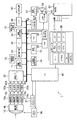
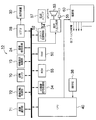
- FIG. 1 is a block diagram showing an embodiment of a monocular stereoscopic imaging device 1.
- This monocular stereoscopic imaging device 1 records a captured image on a recording medium 57, and the operation of the entire device is centrally controlled by a central processing unit (CPU) 40. Further, the operation power supply of each block of the apparatus is supplied from the power supply unit 60.
- CPU central processing unit
- the monocular three-dimensional imaging device 1 is provided with operation units 38 such as a shutter operation unit, a mode operation unit, a reproduction operation unit, a MENU / OK operation unit, a cross operation unit, and a BACK operation unit.
- operation units 38 such as a shutter operation unit, a mode operation unit, a reproduction operation unit, a MENU / OK operation unit, a cross operation unit, and a BACK operation unit.
- a signal from the operation unit 38 is input to the CPU 40, and the CPU 40 controls each circuit of the monocular stereoscopic imaging device 1 based on the input signal.
- lens drive control aperture drive control
- shooting operation control shutter operation unit half
- image processing control image data recording / playback control
- the shutter operation unit is a means for inputting an instruction to start imaging, and can be constituted by a two-stage stroke type switch composed of so-called “half press” and “full press”.
- a two-stage stroke type switch composed of so-called “half press” and “full press”.
- an S1 ON signal is output, and when the shutter button is further pressed halfway down, an S2 ON signal is output and an S1 ON signal is output.
- Shooting preparation processing such as automatic focus adjustment (AF processing) and automatic exposure control (AE processing) is executed, and when the S2 ON signal is output, shooting processing is executed.
- the shutter operation unit is not limited to a two-stroke type switch composed of half-pressing and full-pressing, and may output an S1 on signal and an S2 on signal in one operation, A switch may be provided to output an S1 on signal and an S2 on signal.
- the operation instruction may be output by touching an area corresponding to the operation instruction displayed on the screen of the touch panel as the operation unit.
- the form of the operation means is not limited to this as long as it instructs the shooting preparation process and the shooting process. Further, the shooting preparation process and the shooting process may be executed continuously by an operation instruction to one operation means.
- the mode operation unit is a means for selecting one of an auto shooting mode for shooting a still image, a manual shooting mode, a scene position such as a person, a landscape, a night view, and a moving image mode for shooting a moving image.
- the reproduction operation unit is means for switching to a reproduction mode in which a still image or a moving image of a stereoscopic image (3D image) or a planar image (2D image) that has been recorded is displayed on the display device 30.
- the MENU / OK operation unit is a means having both a function for instructing to display one or a plurality of menus on the screen of the display device 30 and a function for instructing confirmation and execution of selection contents.
- the cross operation unit is an operation unit that inputs instructions in four directions, up, down, left, and right, and functions as a cursor movement operation unit that selects an item from a menu screen or instructs selection of various setting items from each menu.
- the up / down operation unit of the cross operation unit functions as a zoom operation unit during shooting or a playback zoom operation unit during playback mode, and the left / right operation unit performs frame advance (forward / reverse feed) during playback mode. ) Functions as an operation unit.
- the BACK operation unit is used to delete a desired object such as a selection item, cancel an instruction content, or return to the previous operation state.
- the image light indicating the subject corresponds to four types of viewpoints, top, bottom, left, and right, of a parallax image obtained by pupil division in the vertical and horizontal directions through the imaging lens 12, the microlens ML, and a diaphragm (not shown).
- An image is formed on the light receiving surface of a solid-state imaging device (hereinafter referred to as “CCD”) 16 which is a phase difference image sensor that can be acquired by the pixels 16a to 16d.
- CCD solid-state imaging device
- the imaging lens 12 is driven by a motor driver 36 controlled by the CPU 40, and performs focus control, zoom (focal length) control, and the like.
- the diaphragm is composed of, for example, five diaphragm blades and is driven by a diaphragm driving unit (not shown) controlled by the CPU 40.
- a diaphragm value (F value) F2.8 to F11 is controlled in five steps in increments of 1AV. Is done.
- the CPU 40 performs charge accumulation time (shutter speed) in the CCD 16 and reading control of an image signal from the CCD 16 through the timing generator 37.
- the signal charge accumulated in the CCD 16 is read out as a voltage signal corresponding to the signal charge based on the readout signal applied from the timing generator 37. From the voltage signals read from the pixels 16a to 16d of the CCD 16, R, G, and B signals for each pixel are sampled and held, amplified, and then applied to the A / D converters 20a to 20d, respectively.
- the A / D converter 20 converts R, G, and B signals that are sequentially input into digital R, G, and B signals and outputs them to the image input controller 22.
- the image signal processing unit 24 performs predetermined processing such as offset control, gain control processing including white balance correction and sensitivity correction, gamma correction processing, YC processing, etc., on the digital image signal input via the image input controller 22. Perform signal processing.
- predetermined processing such as offset control, gain control processing including white balance correction and sensitivity correction, gamma correction processing, YC processing, etc.
- the top / bottom / left / right viewpoint image data (3D image data) processed by the image signal processing unit 24 is input to the RAM 50.
- the RAM 50 includes an A area and a B area each storing 3D image data representing a 3D image for one frame.
- 3D image data representing a 3D image for one frame is rewritten alternately in the A area and the B area.
- the written 3D image data is read from an area other than the area where the 3D image data is rewritten in the A area and the B area of the RAM 50.
- the 3D image data read from the RAM 50 is converted into an image signal for stereoscopic display by the 3D image signal processing unit 34, encoded by the video encoder 28, and provided for the stereoscopic display provided on the back of the camera. This is output to the display device 30, whereby a 3D subject image is displayed on the display screen of the display device 30.
- the display device 30 can display a stereoscopic image (left viewpoint image and right viewpoint image) as a directional image having directivity in a specific display parallax direction, here the horizontal direction, by a parallax barrier. It is.
- the stereoscopic image display method adopted by the display device 30 is not limited to this, and each viewpoint image can be viewed individually by using a lenticular lens or wearing special glasses such as polarized glasses or liquid crystal shutter glasses. You can do it.
- the CPU 40 starts the AF operation and the AE operation, and the focus lens in the imaging lens 12 is brought into the in-focus position via the motor driver 36. Control to come to.
- the image data output from the A / D converter 20 when the shutter operation unit is half-pressed is taken into the AE / AWB detection circuit 44.
- the AE / AWB detection circuit 44 integrates the G signals of the entire screen or integrates the G signals that are weighted differently in the central portion and the peripheral portion of the screen, and outputs the integrated value to the CPU 40.
- the CPU 40 calculates the brightness of the subject (shooting Ev value) from the integrated value input from the AE / AWB detection circuit 44, and the aperture value of the aperture for obtaining an appropriate exposure based on this shooting Ev value and the electronic shutter of the CCD 16 ( (Shutter speed) is determined according to the program diagram, the aperture is controlled via the aperture drive unit based on the determined aperture value, and the charge is accumulated in the CCD 16 via the timing generator 37 based on the determined shutter speed. Control the time.
- the brightness of the subject may be calculated based on an external photometric sensor.
- the AF processing unit 42 is a part that performs contrast AF processing or phase difference AF processing.
- the contrast AF process the high-frequency component of the image data in the focus area is extracted from at least one of the left-viewpoint image data and the right-viewpoint image data, and the high-frequency component is integrated to focus.
- An AF evaluation value indicating the state is calculated.
- the AF control is performed by controlling the focus lens in the imaging lens 12 so that the AF evaluation value is maximized.
- phase difference AF processing the phase difference between the image data corresponding to the main pixel and the sub pixel in the focus area in the left viewpoint image data and the right viewpoint image data is detected, and this phase difference is indicated. Based on the information, a defocus amount (a shift amount in a state where the in-focus position is shifted with respect to the target subject) is obtained.
- AF control is performed by controlling the focus lens in the imaging lens 12 so that the defocus amount becomes zero.
- the image data temporarily stored in the RAM 50 is appropriately read out by the image signal processing unit 24, where signal processing including luminance data and color difference data generation processing (YC processing) is performed.
- the YC processed image data (YC data) is stored in the RAM 50 again.
- the YC data is respectively output to the image signal processing unit 24 and subjected to compression processing such as JPEG (joint photographic photographic experts group), and then stored in the memory 48 again.
- a multi-picture file (MP file: a file in which a plurality of images are connected) is generated from YC data (compressed data) of the upper, lower, left, and right viewpoint images stored in the RAM 50, and the MP file is a media recording control unit. 52 and is recorded on the recording medium 57.
- MP file a file in which a plurality of images are connected
- the speaker 53 emits sound according to the control of the sound input / output processing unit 54.
- the contents of the voice are stored in the ROM 55.
- the microphone 56 acquires sound in conjunction with image recording and converts it into an analog sound signal.
- the analog audio signal is converted into compressed digital audio data via the audio input / output processing unit 54 and recorded in the RAM 50 or the recording medium 57.
- the parallax correction unit 63 deconvolves the small area with a restoration filter corresponding to the small area covering each viewpoint image, and restores the corresponding small area of the viewpoint image. Specifically, the parallax correction unit 63 obtains a defocus amount corresponding to each of the small areas based on the phase difference calculated for each of the small areas. A set of defocus amounts corresponding to each of the small areas obtained over the entire effective pixel area is referred to as a defocus map. The parallax correction unit 63 temporarily stores the obtained defocus map in the RAM 50 or the like. The parallax correction unit 63 may detect feature points and corresponding points between the viewpoint images, and create a defocus map based on a difference in position information between the feature points and the corresponding points.
- the ROM 55 restores the image height (distance from the image center, typically the distance from the optical axis center L of the imaging lens 12) and the defocus amount (or subject distance) of each small area in each viewpoint image. Saving the filter.
- the parallax correction unit 63 deconvolves the small area with the restoration filter selected for each small area of each viewpoint image, and restores the corresponding small area of the viewpoint image. Thereby, parallax according to the defocus amount (blur amount) can be given to the image.
- the 3D image signal processing unit 34 When the stereoscopic image display mode is selected from the operation unit 38, the 3D image signal processing unit 34 performs stereoscopic image data for the display device 30 to stereoscopically display the right-eye image and the left-eye image stored in the RAM 50. To synthesize. For example, when the display device 30 adopts the parallax barrier method, the 3D image signal processing unit 34 generates stereoscopic image data in which the image for the right eye and the image for the left eye are divided into strips and the strip images are alternately arranged. And output to the video encoder 28. The image selection unit 71 selects a viewpoint image to be combined with the right-eye image and the left-eye image from the four viewpoint images.
- the image rotation processing unit 72 rotates the image selected by the image selection unit 71 by an angle at which the image is stereoscopically displayed.
- the line-of-sight display control unit 73 displays information indicating the orientation of the display device on the display device 30 such that the image selected by the image selection unit 71 is stereoscopically displayed.
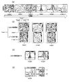
- FIG. 2 (a) is a diagram showing a configuration example of the light receiving surface of the CCD 16.
- FIG. As shown in part (a) of FIG. 2, on the light receiving surface of the CCD 16, a red, blue or green color filter, a pixel group of four viewpoints of pixels A, B, C and D corresponding to the color filter, and Microlenses ML for the four pixel groups are arranged.
- the light receiving units including the color filter, the four pixel group, and the microlens are arranged in a Bayer shape.
- the Bayer array has three primary colors of red (R, r), green (G, g), and blue (B, b) on the four pixel groups formed in a square lattice pattern on the semiconductor substrate surface of the CCD 16.
- red and green filters are alternately arranged and a row in which the green and blue filters are alternately arranged are alternately provided in the column direction.
- the XY plane is the light receiving surface of the CCD 16
- X is the row direction
- Y direction is the column direction.
- the pixels A and C are located on the left side
- the pixels B and D are located on the right side.
- Z is the optical axis direction of the lens 12, and the direction toward the subject (in this figure, the direction from the front to the back of the page) is defined as the positive direction.
- the monocular three-dimensional imaging device 1 is “horizontal”.
- the monocular stereoscopic imaging device 1 is assumed to be “vertically placed”.
- the monocular stereoscopic imaging device 1 when the monocular stereoscopic imaging device 1 is placed horizontally and the positive direction of Y (the direction from the column C toward the column A) is vertically upward, the monocular stereoscopic imaging device 1 is assumed to be “ordinary horizontal placement” or “0 ° horizontal placement”.
- the monocular stereoscopic imaging device 1 is placed horizontally, if the positive direction of Y is directed vertically downward, it is assumed that the monocular stereoscopic imaging device 1 is “laterally placed at + 180 °”.
- the monocular stereoscopic imaging device 1 is placed vertically, but the positive direction of X (the direction from the pixel A to the pixel B) is vertically upward, that is, a monocular.
- the stereoscopic imaging device 1 is rotated 90 ° counterclockwise as viewed from the photographer, it is assumed that the monocular stereoscopic imaging device 1 is “+ 90 ° portrait”.
- the monocular stereoscopic imaging device 1 is placed vertically, but when the positive direction of X is directed vertically downward, that is, the monocular stereoscopic imaging device 1 is viewed from the photographer. It is assumed that the monocular three-dimensional imaging device 1 is “vertically placed at ⁇ 90 °” when rotated 90 ° clockwise.
- Attitude information including the rotation direction and rotation angle of the CCD 16 around the Z axis is detected by an attitude sensor 70 such as a gyroscope.
- the CPU 40 controls the posture sensor 70 to detect posture information at the timing of starting imaging when the shutter operation unit is half-pressed or fully pressed.
- the posture information obtained from the posture sensor 70 is recorded on the recording medium 57 in association with the vertical, horizontal, and parallax images.
- this posture information is recorded as tag information (such as an Exif rotation tag) of an image file that stores vertical, horizontal, and parallax images.
- the monocular stereoscopic imaging device 1 at the time of capturing the four-viewpoint image can perform “normal horizontal placement”, “+ 180 ° horizontal placement”, “ ⁇ 90 ° vertical placement”, “+ 90 °”. It is possible to determine which state is “vertically placed”.
- the subject light incident on the pixel group is divided in the horizontal direction (left-right direction) and the vertical direction (up-down direction) by pupil dividing means such as a light shielding member and a mirror (not shown). Accordingly, a subject image having parallax in the vertical (up and down) direction and the horizontal (left and right) direction is formed on each pixel constituting the four pixel group.
- FIG. 3 is a flowchart of the synthesis process executed by the monocular stereoscopic imaging device 1.
- a program for causing the monocular stereoscopic imaging device 1 to execute the following processing is recorded in a computer-readable recording medium such as the ROM 55. This process starts in response to the selection of the stereoscopic display mode from the operation unit 38.
- This process can also be executed by an information processing apparatus other than the monocular stereoscopic imaging apparatus 1, such as a stereoscopic display apparatus 10 or a personal computer described later.
- the image selection unit 71 reads a set of four parallax images and posture information at the time of acquisition of the parallax images from the RAM 50 and the recording medium 57. In the recording medium 57, a set of four parallax images is recorded as an MP file. The image selection unit 71 determines whether or not the parallax image is captured “0 ° horizontally” from the read posture information. If Yes, the process proceeds to S2. If No, the process proceeds to S3.
- the image selection unit 71 selects the image signal from the pixel A and the image signal from the pixel C as a synthesis source image of the synthesized image L, and synthesizes the image signal from the pixel B and the image signal from the pixel D. Select the image from which the image R is to be synthesized.
- the 3D image signal processing unit 34 combines the image signal from the pixel A and the image signal from the pixel C, the image signal from the pixel B, and the image signal from the pixel D according to the selection of the image selection unit 71. A composite image R is created.
- the 3D image signal processing unit 34 determines whether the parallax image was shot with “+ 90 ° portrait” or the parallax image was taken with “ ⁇ 90 ° portrait” from the read posture information. . If Yes (the parallax image was captured with “+ 90 ° portrait”), the process proceeds to S4. If No (the parallax image was captured with “ ⁇ 90 ° portrait”), the process proceeds to S5.
- the image selection unit 71 selects the image signal from the pixel A and the image signal from the pixel B as a synthesis source image of the synthesized image L, and synthesizes the image signal from the pixel C and the image signal from the pixel D. Select the image from which the image R is to be synthesized.
- the 3D image signal processing unit 34 creates a composite image L of the pixels A and B and a composite image R of the pixels C and D according to the selection of the image selection unit 71.
- the image selection unit 71 selects the image signal from the pixel C and the image signal from the pixel D as the source image of the composite image L, and combines the image signal from the pixel A and the image signal from the pixel B. Select the image from which the image R is to be synthesized.
- the 3D image signal processing unit 34 creates a composite image L of the pixels C and D and a composite image R of the pixels A and B according to the selection by the image selection unit 71.
- the 3D image signal processing unit 34 controls the video encoder 28 to display the composite image L on the display device 30 as the left-eye display image and the composite image R as the right-eye display image.
- FIG. 4 shows a parallax image synthesized corresponding to the arrangement direction of the monocular stereoscopic imaging device 1.
- the monocular three-dimensional imaging device 1 When the monocular three-dimensional imaging device 1 is in “ordinary horizontal position” as viewed from the observer as in the part (a) of FIG. 4, the orientation of the imaging surface is as in the part (a) of FIG. 2.
- a left-right parallax exists between the composite image L of the pixels A and C generated in S2 and the composite image R of the pixels B and D. Therefore, the composite image L is an image for left eye display, and the composite image R is an image for right eye display.
- the monocular three-dimensional imaging device 1 becomes “+ 90 ° vertically placed” (portion (b) in FIG. 2) rotated + 90 ° counterclockwise from “normal landscape”, the pixel A generated in S4 A parallax in the left-right direction exists between the combined image L of B and B and the combined image R of the pixels C and D. Therefore, the composite image L is an image for left eye display, and the composite image R is an image for right eye display.
- the monocular 3D imaging device 1 When the monocular 3D imaging device 1 becomes “-90 ° vertical” (part (c) of FIG. 2) rotated by ⁇ 90 ° counterclockwise from “normal horizontal placement”, it is generated in S5. There is a left-right parallax between the synthesized image L of the pixels C and D and the synthesized image R of the pixels A and B. For this reason, the synthesized image L is an image for left-eye display, and the synthesized image R is an image for right eye display.
- the composite images L and R can be generated in accordance with the orientation of the monocular stereoscopic imaging device 1 during imaging, and the composite images L and R can be displayed as stereoscopic images.
- composite images L and R for left eye display and right eye display were created and displayed.
- the monocular three-dimensional imaging device 1 can also record the combination of the composite images L and R on the recording medium 57 instead of displaying the composite images L and R. In this way, in the monocular three-dimensional imaging apparatus 1 capable of acquiring the vertical and horizontal parallax images, if only the vertical parallax image or the horizontal parallax image is combined and recorded, all the vertical and horizontal parallax images are recorded. Data amount is halved compared to recording.
- the recording medium 57 may include a frame composed of the composite images L and R (two viewpoint images) and a frame composed of the upper, lower, left, and right parallax images that are not combined (four viewpoint images). Further, since the orientation of the monocular stereoscopic imaging device 1 at the time of imaging does not necessarily match the orientation of the display device 30 at the time of stereoscopic display, even if a frame composed of the composite images L and R is displayed as it is, stereoscopic display may not be obtained. .
- frames Image1 to Image6 are recorded on the recording medium 57 in accordance with the shooting date and time.
- frames Image1 to Image3 are a set of four images having parallax in the horizontal and vertical directions.
- the frames Image 4 and 5 are a set of two images having parallax in the horizontal direction.
- Image 6 is a set of images having parallax in the vertical direction.
- Image4 ⁇ 5 is generated in S4 of the above-described combining process
- Image6 is generated in S5 of the above-described combining process.
- Image1 to Image5 are recognized as stereoscopic images if a set of images having a parallax in the horizontal direction is placed on the display device 30 placed horizontally at 0 ° as it is. This is the same as S2 in the above synthesis process.
- the orientation of the monocular stereoscopic imaging device 1 at the time of imaging is vertical at ⁇ 90 ° and does not coincide with the horizontal orientation of 0 ° at the time of viewing the image. For this reason, when the image 6 is displayed as it is with the monocular stereoscopic imaging device 1 placed horizontally at 0 °, an image rotated by ⁇ 90 ° is displayed. In addition, since the parallax direction of Image6 is the vertical direction, Image6 is not stereoscopically displayed.
- the images 1 to 5 are displayed in 3D, but the image 6 is not displayed in 3D. This makes the user feel uncomfortable and causes eye fatigue.
- next rotation processing is performed for the frames of the two viewpoint images that cannot be browsed as a three-dimensional image as it is.
- FIG. 6 shows a flowchart of the rotation process. This process starts in response to the selection of the stereoscopic display mode from the operation unit 38. It is assumed that the monocular three-dimensional imaging device 1 is horizontally placed at 0 ° when this process is executed. The same processing steps as those already described are given the same reference numerals.
- the 3D image signal processing unit 34 reads the selected parallax image frame from the recording medium 57 in accordance with the frame selection operation to the operation unit 38.
- the 3D image signal processing unit 34 determines whether the read frame is a four-viewpoint image having parallax in the vertical and horizontal directions, or a two-viewpoint image having parallax in the vertical and horizontal directions. In the case of Yes (four viewpoint images), the process proceeds to the composition process. If No (two viewpoint images), the process proceeds to S13.
- the 3D image signal processing unit 34 performs trimming from the top, bottom, left, and right viewpoint image data so that a region arbitrarily designated by the operation unit 38 or the like has a parallax in any one direction, and the trimmed two viewpoint images May be read out as a frame of a parallax image, and the process may proceed to S13.
- the 3D image signal processing unit 34 determines whether the read frame is a two-viewpoint image having a parallax in the same horizontal direction as the display parallax direction of the display device 30 or a vertical parallax different from the display parallax direction of the display device 30. To determine whether the image is a two-viewpoint image. In the case of Yes (parallax in the left-right direction), the process proceeds to S14. In the case of No (vertical parallax), the process proceeds to S15.
- the 3D image signal processing unit 34 synthesizes stereoscopic image data for performing stereoscopic display from the read parallax images of the frames.
- the display device 30 performs stereoscopic display based on the stereoscopic image data.
- the image rotation processing unit 72 calculates the angle difference from the posture information at the time of obtaining the parallax image to the current posture information, and rotates the parallax image of the read frame in a direction to eliminate the angle difference.
- the 3D image signal processing unit 34 synthesizes stereoscopic image data for performing stereoscopic display from the parallax image after rotation.
- the display device 30 performs stereoscopic display based on the stereoscopic image data.
- the image rotation processing unit 72 reads out the posture information at the time of acquiring the corresponding parallax image before trimming as the posture information at the time of acquiring the two-viewpoint image. In this way, the rotation process can be similarly performed on the trimmed viewpoint image.
- the two-viewpoint image is automatically rotated in the direction in which stereoscopic display is possible.
- processing that indicates information indicating the direction in which stereoscopic display is possible to the user is executed. May be.
- FIG. 8 shows a flowchart of notification processing according to the second embodiment. This process starts in response to the selection of the stereoscopic display mode from the operation unit 38.
- the same processing steps as those described above are denoted by the same reference numerals.
- S11 to S13 are the same as the rotation process. However, when it determines with No in S13, it progresses to S21.
- the 3D image signal processing unit 34 notifies that the parallax direction of the parallax image is different from the display parallax direction.
- a parallax image Image6 made up of the combined images R and L as shown in part (a) of FIG. 9 is displayed.
- the composite images R and L are created in S4 of the composite process.
- the posture information at the time of photographing (the top and bottom direction at the time of photographing of the image is represented by a graphic, and the text explaining the rotation direction in which stereoscopic display is possible is also displayed. If the user recognizes this notification and rotates the image, the user can understand that the image is displayed three-dimensionally.After this notification processing, the rotation processing may be executed in accordance with an instruction from the user.
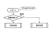
- the rotation process or the notification process may be executed in response to an instruction to turn on or off the function of rotating the viewpoint image.
- FIG. 10 shows the flowchart.
- notification that the image is automatically rotated or the parallax direction of the parallax image is different from the display parallax direction is performed in accordance with an instruction from the user.
- ⁇ Fourth embodiment> When the display device 30 can stereoscopically display parallax not only in the horizontal direction but also in the vertical direction (for example, Patent Document 3), in the notification processing of the second and third embodiments, instead of indicating the rotation direction of the image, the stereoscopic view is displayed. You may notify the information which shows the rotation direction of the display apparatus 30 which becomes possible.
- FIG. 11 is a flowchart of notification processing according to the fourth embodiment.
- the line-of-sight display control unit 73 displays information indicating the rotation direction of the display device 30 that enables stereoscopic viewing.
- Image1 to Image6 as shown in part (a) of Fig. 5 are selected and displayed by frame advance.
- Image6 is created in S4 of the synthesis process and has vertical parallax.
- Image 6 has parallax in the vertical direction
- the parallax direction of Image 6 matches the binocular parallax direction on the left and right. Is recognized as a stereoscopic image. Therefore, as shown in FIG. 12, information I such as graphics and characters indicating the orientation of the display device 30 capable of stereoscopic viewing is displayed. This process is performed instead of S22 of the notification process.
- the parallax direction of Image6 and the display parallax direction of the display device 30 coincide with each other, so that the user can visually recognize the stereoscopic image.
- the image may be automatically rotated as in the above rotation process, but if the user himself / herself rotates the display device 30 in an appropriate direction and stereoscopic display is established, the user is shown the appropriate rotation direction, The actual rotation may be left to the user.
- the 3D image signal processing unit 34 may indicate information such as a figure and characters in a direction in which stereoscopic display is possible when a set of images having parallax in the vertical and horizontal directions is selected (FIG. 13). For a set of planar images that cannot be stereoscopically displayed, information such as graphics and characters indicating that planar display is possible may be displayed (FIG. 14).
- information indicating that a stereoscopic image in the vertical direction can be displayed may be indicated when a set of images having parallax in both the vertical and horizontal directions is selected.
- FIG. 15 is a flowchart of the notification process according to the fifth embodiment.
- S11 to S15 are the same as above, but if S11 is Yes, the process proceeds to the synthesis process, and then proceeds to S41.
- the line-of-sight display control unit 73 displays an icon M indicating that a vertical stereoscopic image can be displayed on the selected frame.
- FIG. 16 shows an example.
- both the image set consisting only of the parallax images in the horizontal direction and the image set consisting of the parallax images in the vertical direction can be stereoscopically displayed, but only one image set is stereoscopically displayed.
- the viewer may not be aware of the presence of the other image set.
- the user can know the presence of a parallax image that can display a stereoscopic image by rotating by visually recognizing the icon M.
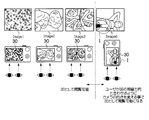
- a representative image (planar image, thumbnail image, etc.) of an image having vertical parallax that can be stereoscopically displayed may be displayed.
- thumbnail J1 of an image having parallax in the vertical direction of Image1 is displayed together with Image1.
- This thumbnail is created by reducing Image1-U or Image1-D having the vertical parallax in part (b) of FIG.
- the representative image of the image having the parallax in the vertical direction of the selected frame is displayed. Instead, all the parallax images in each direction that can be stereoscopically displayed may be displayed.
- Image1 includes Image1-1 and Image1-2.
- Image1-1 and Image1-2 are a set of two parallax images each having a parallax in the horizontal direction and a parallax in the vertical direction.
- stereoscopic images obtained by rotating a set of images Image1-1 having parallax in the left-right direction and a set of images Image1-2 having binocular parallax in the vertical direction by 90 ° are sequentially displayed.
- all images in each direction that can be stereoscopically displayed may be displayed on one screen.
- each of an image set Image1-1 having binocular parallax in the horizontal direction and a stereoscopic image Image1-2 obtained by rotating a set of images having binocular parallax in the vertical direction by 90 ° on one screen indicate.
- both stereoscopic images with different parallax directions may be displayed, and in the second frame display, only the one selected from both stereoscopic images by the operation unit 38 may be displayed. .
- FIG. 20 is a block diagram of the stereoscopic display device 10 according to the seventh embodiment.
- Blocks relating to display of a stereoscopic image equivalent to the monocular stereoscopic imaging device 1 are denoted by the same reference numerals as those of the monocular stereoscopic imaging device 1.
- the recording medium 57 records the parallax image captured by the monocular stereoscopic imaging device 1.
- the operation unit 38 mainly accepts operations related to image display and does not need to accept operations related to imaging.
- the above processing can be repeated every time a set of parallax images (frames) capable of displaying a composite image is selected from the recording medium 57.
- FIG. 21 is a block diagram of the stereoscopic display device 100 according to the eighth embodiment.
- Blocks relating to display of a stereoscopic image equivalent to the monocular stereoscopic imaging device 1 are denoted by the same reference numerals as those of the monocular stereoscopic imaging device 1.
- the stereoscopic display device 100 is connected to an external device 80 storing images such as a personal computer, a game machine, a mobile phone, a smartphone, an HDD recorder, and a Blu-ray recorder from a wired communication path such as an HDMI (High-Definition Multimedia Interface) cable, Bluetooth (registered)
- a recording medium 57 that is a detachable storage medium such as a USB memory or a memory card or a built-in storage medium is mounted via an external input unit 75 including a wireless communication path such as a trademark) or a wireless LAN station. An input of a set of parallax images is received from the media recording control unit 52.
- FIG. 22 is a flowchart of the composition process executed by the stereoscopic display device 100.
- a program for causing the stereoscopic display device 100 to execute the following processing is recorded on a computer-readable recording medium such as the ROM 55.
- the stereoscopic display device 100 receives an input of a set of four parallax images from the external device 80 or the recording medium 57.
- the stereoscopic display device 100 After S1, the stereoscopic display device 100 performs the same processing as in FIG. 3 on the set of parallax images input from the external device 80 or the recording medium 57. Thereby, also about the group of parallax images input from the external device 80, a stereoscopic image can be combined according to the direction at the time of imaging and displayed on the display device 30, as in the first embodiment.
- the stereoscopic display device 100 can perform the processes of FIGS. 6, 8, 10, 11, and 15 on the set of parallax images input from the external device 80 or the recording medium 57.
- a stereoscopic image obtained by executing the various processes (compositing process, rotation process, notification process) described in the first to sixth embodiments is stored in a buffer of the display device 30 (not shown), and the display device 30 is displayed. May display stereoscopic images stored in this buffer. That is, the stereoscopic display device 100 only needs to include blocks necessary for executing each process other than the stereoscopic image display, and the display device 30 does not necessarily have to be provided integrally.
- An external device such as a compatible TV may be used. That is, the stereoscopic display device 100 may control image display on the external display device 30.
- the stereoscopic display device 100 includes means for acquiring the display parallax direction of the external display device 30.
- the display parallax direction (horizontal direction or the like) of the display device 30 is stored in the ROM 55 in advance, and the CPU 40 acquires this from the ROM 55 when the above processing is executed.
- the CPU 40 may acquire the display parallax direction of the display device 30 from the external device 80 via a network such as the external input unit 75.
- the CPU 40 may communicate with the external display device 30 and acquire the display parallax direction from the display device 30. Then, in S13 of the process of FIG.
- the process proceeds to S14, and if different, the process proceeds to S15.
- the display parallax direction of the external display device 30 can also be made to coincide with the parallax direction of the read frame by rotating the two-viewpoint image.
- the processes of FIGS. 8, 11, and 15 can be applied to the external display device 30.
Abstract
In the present invention, in the case where a parallax image that cannot be stereoscopically displayed in the current state thereof is selected, the selected image is rotated in an appropriate direction and stereoscopically displayed, and a sense of discomfort is therefore not imparted upon the user. Furthermore, in the present invention, a direction in which it becomes possible for the selected parallax image to be stereoscopically viewed is displayed by means of information such as a diagram. The user perceives this information and is able to understand that the image will be stereoscopically displayed if made to rotate.
Description
本発明は立体画像表示制御装置および立体画像表示制御方法に係り、特に撮影レンズの4方向の異なる領域を通過した被写体像をそれぞれ撮像素子に結像させることで得られた4つの視差画像に基づいて立体表示をする技術に関する。
The present invention relates to a stereoscopic image display control device and a stereoscopic image display control method, and in particular, based on four parallax images obtained by forming, on an image sensor, subject images that have passed through different regions in four directions of a photographing lens. The present invention relates to a technology for stereoscopic display.
特許文献1には、複数の撮像画像に1つのマイクロレンズを配置し、左右視差画像、上下視差画像の方法を生成する撮像装置が開示されている。
Patent Document 1 discloses an imaging apparatus that arranges a single microlens for a plurality of captured images and generates a method of right and left parallax images and upper and lower parallax images.
また、特許文献2には、左右視差画像、上下視差画像の両方を同時に発生させることのできるディスプレイ装置が開示されている。
Further, Patent Document 2 discloses a display device that can simultaneously generate both a left and right parallax image and an upper and lower parallax image.
特許文献3には、画像を3次元で表現する立体画像表示装置の画素を奇数列画素及び偶数列画素の対に区分して配列形成し、奇数列画素及び偶数列画素の前方に光線の水平及び垂直成分のいずれか一側方向だけをそれぞれ通過させる偏光手段を設けてある立体画像表示装置が開示されている。
In Patent Document 3, pixels of a stereoscopic image display device that expresses an image in three dimensions are divided and formed into pairs of odd-numbered pixels and even-numbered pixels, and the light rays are horizontally placed in front of the odd-numbered pixels and even-numbered pixels. And a stereoscopic image display device provided with polarizing means for passing only one of the vertical components.
その他、本発明に関連する従来技術として、下記特許文献4~8が挙げられる。
Other conventional techniques related to the present invention include the following Patent Documents 4 to 8.
特許文献1のような、4つのフォトダイオードに対して、1つのマイクロレンズの構成を持つベイヤ配列型の撮像素子を用いて、上下左右方向の視差画像を取得することができる。
A parallax image in the vertical and horizontal directions can be obtained using a Bayer array type imaging device having a configuration of one microlens for four photodiodes as in Patent Document 1.
上下左右方向の視差画像を取得した場合は、閲覧者の視差の方向や表示機器の向きに合わせて適切な立体視となるように視差画像を回転して表示させることができる。例えば、表示視差(表示面上で両眼視差を生じる方向)を左右方向に有する立体表示装置が上下方向の視差画像を立体表示する場合、当該視差画像を+90°または-90°回転すれば、瞳分割方向が表示視差方向と一致し、立体視できる。なお、立体表示の方式は、パララックスバリア方式、レンチキュラ方式、液晶シャッタ方式などがある。
When a parallax image in the vertical and horizontal directions is acquired, the parallax image can be rotated and displayed so as to obtain an appropriate stereoscopic view according to the parallax direction of the viewer and the orientation of the display device. For example, when a stereoscopic display device having a display parallax (a direction in which binocular parallax occurs on the display surface) in the left-right direction stereoscopically displays a vertical parallax image, if the parallax image is rotated by + 90 ° or −90 °, The pupil division direction matches the display parallax direction, and stereoscopic viewing is possible. Note that three-dimensional display methods include a parallax barrier method, a lenticular method, and a liquid crystal shutter method.
しかし、上下方向の視差画像のみ、あるいは左右方向の視差画像を取得した場合は、画像やディスプレイを回転すると立体表示ができなくなる。例えば、表示機器のディスプレイが水平方向に置かれる(横置き)ことで両眼視差を生じる場合、左右方向の視差画像は、横置きで立体表示される。しかし、ディスプレイを90°回転する(縦置き)と、左右方向の視差画像は立体表示として認識できない。また、上下方向の視差画像が取得されていないので、縦置きのディスプレイで上下方向の視差画像を立体表示することもできない。
However, when only a vertical parallax image or a horizontal parallax image is acquired, stereoscopic display becomes impossible when the image or display is rotated. For example, when binocular parallax is generated by placing the display of the display device in the horizontal direction (horizontal placement), the parallax image in the left-right direction is stereoscopically displayed horizontally. However, if the display is rotated by 90 ° (vertically placed), the left-right parallax image cannot be recognized as a stereoscopic display. In addition, since the vertical parallax image has not been acquired, the vertical parallax image cannot be stereoscopically displayed on the vertical display.
左右方向の視差画像のみからなる画像セットと、上下方向の視差画像からなる画像セットが、同じ記録媒体に取得されて混在しているとする。表示機器がこれらを順次コマ送りで立体表示する場合、視差画像の視差方向が、観察者から見た表示機器の両眼視差方向と合致していないと、立体表示として認識されない。一方、視差画像の視差方向が、観察者から見た表示機器の両眼視差方向と合致していると、立体表示として認識される。観察者は、コマ送りの最中に、コマによって立体感を認識できたりできなかったりすると、違和感を覚え、観察者の目を疲れさせる。
Suppose that an image set consisting only of left and right parallax images and an image set consisting of vertical parallax images are acquired and mixed on the same recording medium. When the display device stereoscopically displays these images sequentially by frame advance, the parallax image is not recognized as a stereoscopic display unless the parallax direction of the parallax image matches the binocular parallax direction of the display device viewed from the observer. On the other hand, when the parallax direction of the parallax image matches the binocular parallax direction of the display device viewed from the observer, it is recognized as stereoscopic display. If the observer cannot recognize the stereoscopic effect by the frame during frame advance, the observer feels uncomfortable and tires the eyes of the observer.
本発明はこのような事情に鑑みてなされたもので、表示装置の視差方向に対応して外部から入力された視差画像を適切に表示可能にすることを目的とする。
The present invention has been made in view of such circumstances, and an object thereof is to appropriately display a parallax image input from the outside corresponding to the parallax direction of a display device.
本発明は、視差を有する画像の組を外部から入力可能な入力部と、入力部に入力された画像の組の中から所望の画像の組を選択する選択部と、視差を有する画像の組を立体表示可能な表示部の特定の表示視差方向と選択部の選択した画像の組である選択画像組の視差の方向である画像視差方向とが一致するか否かを判断する判断部と、判断部が表示視差方向と画像視差方向とは不一致であると判断したことに応じて、表示視差方向と画像視差方向とが一致する角度だけ選択画像組の各画像を回転して表示部に立体表示するよう制御する表示制御部と、を備える立体画像表示制御装置を提供する。
The present invention relates to an input unit capable of inputting a set of images having parallax from the outside, a selection unit for selecting a desired set of images from the set of images input to the input unit, and a set of images having parallax. A determination unit that determines whether or not a specific display parallax direction of the display unit capable of stereoscopic display matches an image parallax direction that is a parallax direction of a selected image set that is a set of images selected by the selection unit; In response to determining that the display parallax direction and the image parallax direction do not match, the determination unit rotates each image of the selected image set by an angle at which the display parallax direction and the image parallax direction match, and There is provided a stereoscopic image display control device including a display control unit that controls display.
表示制御部は、表示視差方向が水平方向でありかつ画像視差方向が垂直方向である場合、選択画像組の各画像を90°回転して表示部に立体表示するよう制御する。
When the display parallax direction is the horizontal direction and the image parallax direction is the vertical direction, the display control unit controls to rotate each image of the selected image set by 90 ° and display the image on the display unit in a stereoscopic manner.
選択画像組を回転するか否かを設定する設定部を備え、表示制御部は、設定部が画像を回転する設定をした場合、表示視差方向と画像視差方向とが一致する角度だけ選択画像組の各画像を回転して表示部に立体表示するよう制御する。
The display control unit includes a setting unit that sets whether to rotate the selected image set. When the setting unit is set to rotate the image, the display control unit selects the selected image set by an angle at which the display parallax direction matches the image parallax direction. These images are rotated so as to be displayed in a stereoscopic manner on the display unit.
表示制御部は、設定部が画像を回転しない設定をした場合、表示視差方向と画像視差方向とが一致するような画像の回転角度または表示部の回転方向を示す情報を表示部に表示するよう制御する。
The display control unit displays information indicating the rotation angle of the image or the rotation direction of the display unit on the display unit so that the display parallax direction and the image parallax direction match when the setting unit is configured not to rotate the image. Control.
本発明は、特定の表示視差方向に視差を有する画像の組を立体表示可能な表示部と、視差を有する画像の組を外部から入力可能な入力部と、入力部の入力された画像の組の中から所望の画像の組を選択する選択部と、表示視差方向と選択部の選択した画像の組である選択画像組の視差の方向である画像視差方向とが一致するか否かを判断する判断部と、判断部が表示視差方向と画像視差方向とは不一致であると判断したことに応じて、表示視差方向と画像視差方向とが一致するような画像の回転角度または表示部の回転方向を示す情報を表示部に表示するよう制御する表示制御部と、を備える立体画像表示制御装置を提供する。
The present invention provides a display unit capable of stereoscopically displaying a set of images having parallax in a specific display parallax direction, an input unit capable of inputting a set of images having parallax from the outside, and a set of images input to the input unit A selection unit that selects a desired set of images from the image, and determines whether the display parallax direction and the image parallax direction that is the parallax direction of the selected image set that is a set of images selected by the selection unit match And the rotation angle of the image or the rotation of the display unit so that the display parallax direction and the image parallax direction match in accordance with the determination that the display parallax direction and the image parallax direction do not match. There is provided a stereoscopic image display control device including a display control unit that controls to display information indicating a direction on a display unit.
情報は、画像の回転角度または表示部の回転方向を示す図形および/または文字である。
Information is a figure and / or a character indicating the rotation angle of the image or the rotation direction of the display unit.
表示視差方向は水平方向であり、入力部は、水平方向または垂直方向の単一の方向に視差を有する画像の組ならびに水平方向および垂直方向の複数の方向に視差を有する画像の組を入力可能である。
The display parallax direction is the horizontal direction, and the input unit can input a set of images having parallax in a single horizontal or vertical direction and a set of images having parallax in a plurality of horizontal and vertical directions It is.
表示制御部は、選択画像組が水平および垂直方向に視差を有する場合、水平方向に視差を有する画像の組を表示部に立体表示するとともに、垂直方向に視差を有する画像の組を立体表示することが可能な旨を示す情報を表示部に表示するよう制御する。
When the selected image set has parallax in the horizontal and vertical directions, the display control unit stereoscopically displays the set of images having parallax in the horizontal direction on the display unit, and stereoscopically displays the set of images having parallax in the vertical direction. Control is performed so that information indicating that the information can be displayed is displayed on the display unit.
表示制御部は、選択画像組が水平および垂直方向に視差を有する場合、水平方向に視差を有する画像の組を表示部に立体表示するとともに、垂直方向に視差を有する画像の組を表示視差方向と一致するように回転した状態を示す代表画像を表示部に表示するよう制御する。
When the selected image set has parallax in the horizontal and vertical directions, the display control unit stereoscopically displays the set of images having parallax in the horizontal direction on the display unit, and displays the set of images having parallax in the vertical direction. To display on the display unit a representative image showing a state of rotation so as to match.
表示制御部は、選択画像組が水平および垂直方向に視差を有する場合、垂直方向に視差を有する画像の組を表示視差方向と一致する角度だけ回転した回転画像の組と、水平方向に視差を有する画像の組を、順次または同時に表示部に立体表示するよう制御する。
When the selected image set has parallax in the horizontal and vertical directions, the display control unit converts the set of images having parallax in the vertical direction by rotating the set of rotated images by an angle that matches the display parallax direction and the parallax in the horizontal direction. Control is performed to stereoscopically display the set of images on the display unit sequentially or simultaneously.
垂直および水平方向への瞳分割により被写体からの光束を4つの光束に分割し、4つの光束を、それぞれ特定配列のカラーフィルタに対応する4つの光電変換素子群に結像して光電変換することで、各カラーフィルタに対応する色成分を有する4つの視点画像信号の組を出力する撮像部と、撮像部の出力した各カラーフィルタに対応する色成分を有する4つの視点画像信号の組のうち、垂直方向に隣接する光電変換素子から得られた2つの視点画像信号同士または水平方向に隣接する光電変換素子から得られた2つの視点画像信号同士を合成することで、水平方向に視差を有する画像の組または垂直方向に視差を有する画像の組を作成する合成部と、を備え、入力部は、合成部の作成した水平方向に視差を有する画像の組または垂直方向に視差を有する画像の組を入力する。
The light beam from the subject is divided into four light beams by pupil division in the vertical and horizontal directions, and the four light beams are imaged on four photoelectric conversion element groups corresponding to the color filters of a specific arrangement, respectively, and subjected to photoelectric conversion. An imaging unit that outputs a set of four viewpoint image signals having color components corresponding to each color filter, and a set of four viewpoint image signals having color components corresponding to each color filter output by the imaging unit By combining the two viewpoint image signals obtained from the photoelectric conversion elements adjacent in the vertical direction or the two viewpoint image signals obtained from the photoelectric conversion elements adjacent in the horizontal direction, there is a parallax in the horizontal direction. A composition unit that creates a set of images or a set of images having parallax in the vertical direction, and the input unit is configured to create a set of images having parallax in the horizontal direction created by the synthesis unit or in the vertical direction. Inputting a set of images having the difference.
合成部は、撮像部の出力した各カラーフィルタに対応する色成分を有する4つの視点画像信号の組のうち、垂直方向に隣接する光電変換素子から得られた2つの視点画像信号同士および水平方向に隣接する光電変換素子から得られた2つの視点画像信号同士を合成することで、水平方向に視差を有する画像の組および垂直方向に視差を有する画像の組を作成し、入力部は、合成部の作成した水平方向に視差を有する画像の組および垂直方向に視差を有する画像の組を入力する。
The combining unit includes two viewpoint image signals obtained from photoelectric conversion elements adjacent in the vertical direction and a horizontal direction among a set of four viewpoint image signals having color components corresponding to the color filters output from the imaging unit. By combining the two viewpoint image signals obtained from the photoelectric conversion elements adjacent to each other, a set of images having parallax in the horizontal direction and a set of images having parallax in the vertical direction are created. A set of images having parallax in the horizontal direction and a set of images having parallax in the vertical direction are input.
表示制御部は、選択画像組が水平および垂直方向に視差を有する場合、撮像部の出力時における表示視差方向に一致する視差を有する画像の組を選択し、選択された画像の組を立体表示するよう制御する。
When the selected image set has parallax in the horizontal and vertical directions, the display control unit selects a set of images having parallax that matches the display parallax direction at the time of output of the imaging unit, and stereoscopically displays the selected set of images Control to do.
撮像部の4つの視点画像信号の組の出力時の姿勢情報を検出する姿勢情報検出部を備え、合成部は、姿勢情報検出部の検出した姿勢情報に基づき、垂直方向に隣接する光電変換素子から得られた左の視点画像信号の組および右の視点画像信号の組を判別し、判別された左の視点画像信号の組を合成するとともに、判別された右の視点画像信号の組を合成することで、水平方向に視差を有する画像の組を作成する。
A posture information detection unit that detects posture information at the time of outputting a set of four viewpoint image signals of the imaging unit, and the combining unit is a photoelectric conversion element adjacent in the vertical direction based on the posture information detected by the posture information detection unit The left viewpoint image signal set and the right viewpoint image signal set obtained from the above are discriminated, the discriminated left viewpoint image signal set is synthesized, and the discriminated right viewpoint image signal set is synthesized Thus, a set of images having parallax in the horizontal direction is created.
表示部の特定の表示視差方向を取得する表示視差方向取得部を備え、判断部は、表示視差方向取得部の取得した表示視差方向と選択部の選択した画像の組である選択画像組の視差の方向である画像視差方向とが一致するか否かを判断する。
A display parallax direction acquisition unit that acquires a specific display parallax direction of the display unit is provided, and the determination unit is a parallax of a selected image set that is a set of the display parallax direction acquired by the display parallax direction acquisition unit and the image selected by the selection unit It is determined whether or not the image parallax direction, which is the same direction, matches.
本発明は、立体画像表示制御装置が、視差を有する画像の組を外部から入力するステップと、入力された画像の組の中から所望の画像の組を選択するステップと、視差を有する画像の組を立体表示可能な表示部の特定の表示視差方向と選択した画像の組である選択画像組の視差の方向である画像視差方向とが一致するか否かを判断するステップと、表示視差方向と画像視差方向とは不一致であると判断したことに応じて、表示視差方向と画像視差方向とが一致する角度だけ選択画像組の各画像を回転して立体表示するよう制御するステップと、を実行する立体画像表示制御方法を提供する。
According to the present invention, a stereoscopic image display control device inputs a set of images having parallax from the outside, a step of selecting a desired set of images from the set of input images, Determining whether or not a specific display parallax direction of the display unit capable of stereoscopically displaying the set matches an image parallax direction that is a parallax direction of a selected image set that is a set of selected images, and a display parallax direction And a step of controlling each image of the selected image set to be stereoscopically displayed by rotating an angle at which the display parallax direction and the image parallax direction match in response to determining that the image parallax direction and the image parallax direction do not match. A stereoscopic image display control method to be executed is provided.
本発明は、立体画像表示制御装置が、視差を有する画像の組を外部から入力するステップと、入力された画像の組の中から所望の画像の組を選択するステップと、視差を有する画像の組を立体表示可能な表示部の特定の表示視差方向と選択した画像の組である選択画像組の視差の方向である画像視差方向とが一致するか否かを判断するステップと、視差を有する画像の組を立体表示可能な表示部の特定の表示視差方向と画像視差方向とは不一致であると判断したことに応じて、表示視差方向と画像視差方向とが一致するような画像の回転角度または表示部の回転方向を示す情報を表示するよう制御するステップと、を実行する立体画像表示制御方法を提供する。
According to the present invention, a stereoscopic image display control device inputs a set of images having parallax from the outside, a step of selecting a desired set of images from the set of input images, Determining whether or not a specific display parallax direction of a display unit capable of stereoscopically displaying the set matches an image parallax direction that is a parallax direction of a selected image set that is a set of selected images; The rotation angle of the image such that the display parallax direction matches the image parallax direction in response to determining that the specific display parallax direction and the image parallax direction of the display unit capable of stereoscopically displaying the set of images are inconsistent Alternatively, a method of controlling to display information indicating the rotation direction of the display unit is provided.
本発明では、そのままでは立体表示できない視差画像が選択された場合、選択された画像を適切な方向に回転して立体表示するため、ユーザに違和感を与えずに済む。また、本発明では、選択された視差画像が立体視可能となる方向を図形などの情報で表示する。ユーザは、この情報を認識して、画像を回転させれば立体表示されることが理解できる。
In the present invention, when a parallax image that cannot be stereoscopically displayed as it is is selected, the selected image is rotated in an appropriate direction and stereoscopically displayed, so that the user does not feel uncomfortable. In the present invention, the direction in which the selected parallax image can be viewed stereoscopically is displayed as information such as a figure. If the user recognizes this information and rotates the image, the user can understand that the image is displayed three-dimensionally.
<第1実施形態>
図1は単眼立体撮像装置1の実施の形態を示すブロック図である。 <First Embodiment>
FIG. 1 is a block diagram showing an embodiment of a monocular stereoscopic imaging device 1.
図1は単眼立体撮像装置1の実施の形態を示すブロック図である。 <First Embodiment>
FIG. 1 is a block diagram showing an embodiment of a monocular stereoscopic imaging device 1.
この単眼立体撮像装置1は、撮像した画像を記録メディア57に記録するもので、装置全体の動作は、中央処理装置(CPU)40によって統括制御される。また、装置の各ブロックの動作電源は電源部60から供給される。
This monocular stereoscopic imaging device 1 records a captured image on a recording medium 57, and the operation of the entire device is centrally controlled by a central processing unit (CPU) 40. Further, the operation power supply of each block of the apparatus is supplied from the power supply unit 60.
単眼立体撮像装置1には、シャッタ操作部、モード操作部、再生操作部、MENU/OK操作部、十字操作部、BACK操作部等の操作部38が設けられている。この操作部38からの信号はCPU40に入力され、CPU40は入力信号に基づいて単眼立体撮像装置1の各回路を制御し、例えば、レンズ駆動制御、絞り駆動制御、撮影動作制御(シャッタ操作部半押し時から画像記録完了までの処理の制御)、画像処理制御、画像データの記録/再生制御、立体表示用の表示装置30の表示制御、電源オン・オフなどを行う。
シャッタ操作部は、撮像開始の指示を入力するための手段であり、いわゆる「半押し」と「全押し」とからなる2段ストローク式のスイッチで構成されることができる。単眼立体撮像装置1では、シャッタ操作部が半押しされることによってS1オンの信号、半押しから更に押し込む全押しがされることによってS2オンの信号が出力され、S1オン信号が出力されると自動焦点調節(AF処理)や自動露出制御(AE処理)などの撮影準備処理を実行し、S2オン信号が出力されると撮影処理を実行する。 The monocular three-dimensional imaging device 1 is provided withoperation units 38 such as a shutter operation unit, a mode operation unit, a reproduction operation unit, a MENU / OK operation unit, a cross operation unit, and a BACK operation unit. A signal from the operation unit 38 is input to the CPU 40, and the CPU 40 controls each circuit of the monocular stereoscopic imaging device 1 based on the input signal. For example, lens drive control, aperture drive control, shooting operation control (shutter operation unit half) Control of processing from pressing to image recording completion), image processing control, image data recording / playback control, display control of the display device 30 for stereoscopic display, power on / off, and the like.
The shutter operation unit is a means for inputting an instruction to start imaging, and can be constituted by a two-stage stroke type switch composed of so-called “half press” and “full press”. In the monocular stereoscopic imaging device 1, when the shutter operation unit is half-pressed, an S1 ON signal is output, and when the shutter button is further pressed halfway down, an S2 ON signal is output and an S1 ON signal is output. Shooting preparation processing such as automatic focus adjustment (AF processing) and automatic exposure control (AE processing) is executed, and when the S2 ON signal is output, shooting processing is executed.
シャッタ操作部は、撮像開始の指示を入力するための手段であり、いわゆる「半押し」と「全押し」とからなる2段ストローク式のスイッチで構成されることができる。単眼立体撮像装置1では、シャッタ操作部が半押しされることによってS1オンの信号、半押しから更に押し込む全押しがされることによってS2オンの信号が出力され、S1オン信号が出力されると自動焦点調節(AF処理)や自動露出制御(AE処理)などの撮影準備処理を実行し、S2オン信号が出力されると撮影処理を実行する。 The monocular three-dimensional imaging device 1 is provided with
The shutter operation unit is a means for inputting an instruction to start imaging, and can be constituted by a two-stage stroke type switch composed of so-called “half press” and “full press”. In the monocular stereoscopic imaging device 1, when the shutter operation unit is half-pressed, an S1 ON signal is output, and when the shutter button is further pressed halfway down, an S2 ON signal is output and an S1 ON signal is output. Shooting preparation processing such as automatic focus adjustment (AF processing) and automatic exposure control (AE processing) is executed, and when the S2 ON signal is output, shooting processing is executed.
なお、シャッタ操作部は半押しと全押しとからなる2段ストローク式のスイッチの形態に限られず、1回の操作でS1オンの信号、S2オンの信号を出力しても良く、それぞれ個別のスイッチを設けてS1オンの信号、S2オンの信号を出力しても良い。
The shutter operation unit is not limited to a two-stroke type switch composed of half-pressing and full-pressing, and may output an S1 on signal and an S2 on signal in one operation, A switch may be provided to output an S1 on signal and an S2 on signal.
また、タッチ式パネル等により操作指示を行う形態では、これら操作手段としてタッチ式パネルの画面に表示される操作指示に対応する領域をタッチすることで操作指示を出力するようにしても良く、本発明においては撮影準備処理や撮影処理を指示するものであれば操作手段の形態はこれらに限られない。また、1つの操作手段への操作指示で撮影準備処理と撮影処理を連続して実行するようにしても良い。
Further, in the form in which the operation instruction is performed using the touch panel or the like, the operation instruction may be output by touching an area corresponding to the operation instruction displayed on the screen of the touch panel as the operation unit. In the invention, the form of the operation means is not limited to this as long as it instructs the shooting preparation process and the shooting process. Further, the shooting preparation process and the shooting process may be executed continuously by an operation instruction to one operation means.
モード操作部は、静止画を撮影するオート撮影モード、マニュアル撮影モード、人物、風景、夜景等のシーンポジション、および動画を撮影する動画モードのいずれかを選択する手段である。
The mode operation unit is a means for selecting one of an auto shooting mode for shooting a still image, a manual shooting mode, a scene position such as a person, a landscape, a night view, and a moving image mode for shooting a moving image.
再生操作部は、撮影記録した立体視画像(3D画像)、平面画像(2D画像)の静止画又は動画を表示装置30に表示させる再生モードに切り替えるための手段である。MENU/OK操作部は、表示装置30の画面上に1または複数のメニューを表示させる指令を行う機能と、選択内容の確定および実行などを指令する機能とを兼備した手段である。十字操作部は、上下左右の4方向の指示を入力する操作部であり、メニュー画面から項目を選択したり、各メニューから各種設定項目の選択を指示したりするカーソル移動操作手段として機能する。また、十字操作部の上/下操作部は撮影時のズーム操作部あるいは再生モード時の再生ズーム操作部として機能し、左/右操作部は再生モード時のコマ送り(順方向/逆方向送り)操作部として機能する。BACK操作部は、選択項目など所望の対象の消去や指示内容の取消し、あるいは1つ前の操作状態に戻らせる時などに使用される。
The reproduction operation unit is means for switching to a reproduction mode in which a still image or a moving image of a stereoscopic image (3D image) or a planar image (2D image) that has been recorded is displayed on the display device 30. The MENU / OK operation unit is a means having both a function for instructing to display one or a plurality of menus on the screen of the display device 30 and a function for instructing confirmation and execution of selection contents. The cross operation unit is an operation unit that inputs instructions in four directions, up, down, left, and right, and functions as a cursor movement operation unit that selects an item from a menu screen or instructs selection of various setting items from each menu. The up / down operation unit of the cross operation unit functions as a zoom operation unit during shooting or a playback zoom operation unit during playback mode, and the left / right operation unit performs frame advance (forward / reverse feed) during playback mode. ) Functions as an operation unit. The BACK operation unit is used to delete a desired object such as a selection item, cancel an instruction content, or return to the previous operation state.
撮影モード時において、被写体を示す画像光は、撮像レンズ12、マイクロレンズML、不図示の絞りを介して垂直・水平方向に瞳分割された視差画像を、上下左右の4種類の視点に対応する画素16a~16dによって取得可能な位相差イメージセンサである固体撮像素子(以下、「CCD」という)16の受光面に結像される。撮像レンズ12は、CPU40によって制御されるモータドライバ36によって駆動され、フォーカス制御、ズーム(焦点距離)制御等が行われる。絞りは、例えば、5枚の絞り羽根からなり、CPU40によって制御される不図示の絞り駆動部によって駆動され、例えば、絞り値(F値)F2.8 ~F11まで1AV刻みで5段階に絞り制御される。
In the shooting mode, the image light indicating the subject corresponds to four types of viewpoints, top, bottom, left, and right, of a parallax image obtained by pupil division in the vertical and horizontal directions through the imaging lens 12, the microlens ML, and a diaphragm (not shown). An image is formed on the light receiving surface of a solid-state imaging device (hereinafter referred to as “CCD”) 16 which is a phase difference image sensor that can be acquired by the pixels 16a to 16d. The imaging lens 12 is driven by a motor driver 36 controlled by the CPU 40, and performs focus control, zoom (focal length) control, and the like. The diaphragm is composed of, for example, five diaphragm blades and is driven by a diaphragm driving unit (not shown) controlled by the CPU 40. For example, a diaphragm value (F value) F2.8 to F11 is controlled in five steps in increments of 1AV. Is done.
また、CPU40は、タイミングジェネレータ37を介して、CCD16での電荷蓄積時間(シャッタスピード)やCCD16からの画像信号の読み出し制御等を行う。
Further, the CPU 40 performs charge accumulation time (shutter speed) in the CCD 16 and reading control of an image signal from the CCD 16 through the timing generator 37.
CCD16に蓄積された信号電荷は、タイミングジェネレータ37から加えられる読み出し信号に基づいて信号電荷に応じた電圧信号として読み出される。CCD16の画素16a~16dから読み出された電圧信号からは、各画素ごとのR、G、B信号がサンプリングホールドされ、増幅されたのち、それぞれA/D変換器20a~20dに加えられる。A/D変換器20は、順次入力するR、G、B信号をデジタルのR、G、B信号に変換して画像入力コントローラ22に出力する。
The signal charge accumulated in the CCD 16 is read out as a voltage signal corresponding to the signal charge based on the readout signal applied from the timing generator 37. From the voltage signals read from the pixels 16a to 16d of the CCD 16, R, G, and B signals for each pixel are sampled and held, amplified, and then applied to the A / D converters 20a to 20d, respectively. The A / D converter 20 converts R, G, and B signals that are sequentially input into digital R, G, and B signals and outputs them to the image input controller 22.
画像信号処理部24は、画像入力コントローラ22を介して入力するデジタルの画像信号に対して、オフセット処理、ホワイトバランス補正および感度補正を含むゲイン・コントロール処理、ガンマ補正処理、YC処理等の所定の信号処理を行う。
The image signal processing unit 24 performs predetermined processing such as offset control, gain control processing including white balance correction and sensitivity correction, gamma correction processing, YC processing, etc., on the digital image signal input via the image input controller 22. Perform signal processing.
画像信号処理部24で処理された上下左右の視点画像データ(3D画像データ)は、RAM50に入力する。RAM50には、それぞれが1コマ分の3D画像を表す3D画像データを記憶するA領域とB領域とが含まれている。RAM50において1コマ分の3D画像を表す3D画像データがA領域とB領域とで交互に書き換えられる。RAM50のA領域およびB領域のうち、3D画像データが書き換えられている方の領域以外の領域から、書き込まれている3D画像データが読み出される。RAM50から読み出された3D画像データは、3D画像信号処理部34にて立体表示用の画像信号に変換された後、ビデオ・エンコーダ28においてエンコーディングされ、カメラ背面に設けられている立体表示用の表示装置30に出力され、これにより3Dの被写体像が表示装置30の表示画面上に表示される。
The top / bottom / left / right viewpoint image data (3D image data) processed by the image signal processing unit 24 is input to the RAM 50. The RAM 50 includes an A area and a B area each storing 3D image data representing a 3D image for one frame. In the RAM 50, 3D image data representing a 3D image for one frame is rewritten alternately in the A area and the B area. The written 3D image data is read from an area other than the area where the 3D image data is rewritten in the A area and the B area of the RAM 50. The 3D image data read from the RAM 50 is converted into an image signal for stereoscopic display by the 3D image signal processing unit 34, encoded by the video encoder 28, and provided for the stereoscopic display provided on the back of the camera. This is output to the display device 30, whereby a 3D subject image is displayed on the display screen of the display device 30.
この表示装置30は、立体視画像(左視点画像および右視点画像)をパララックスバリアによりそれぞれ特定の表示視差方向、ここでは水平方向への指向性をもった指向性画像として表示できる立体表示手段である。ただし、表示装置30の採用する立体画像表示方式は、これに限らず、レンチキュラレンズを使用するものや、偏光メガネ、液晶シャッタメガネなどの専用メガネをかけることで各視点画像を個別に見ることができるものでもよい。
The display device 30 can display a stereoscopic image (left viewpoint image and right viewpoint image) as a directional image having directivity in a specific display parallax direction, here the horizontal direction, by a parallax barrier. It is. However, the stereoscopic image display method adopted by the display device 30 is not limited to this, and each viewpoint image can be viewed individually by using a lenticular lens or wearing special glasses such as polarized glasses or liquid crystal shutter glasses. You can do it.
操作部38のシャッタ操作部の第1段階の押下(半押し)があると、CPU40は、AF動作およびAE動作を開始させ、モータドライバ36を介して撮像レンズ12内のフォーカスレンズが合焦位置にくるように制御する。また、シャッタ操作部の半押し時にA/D変換器20から出力される画像データは、AE/AWB検出回路44に取り込まれる。
When the first stage pressing (half-pressing) of the shutter operation unit of the operation unit 38 is performed, the CPU 40 starts the AF operation and the AE operation, and the focus lens in the imaging lens 12 is brought into the in-focus position via the motor driver 36. Control to come to. The image data output from the A / D converter 20 when the shutter operation unit is half-pressed is taken into the AE / AWB detection circuit 44.
AE/AWB検出回路44では、画面全体のG信号を積算し、又は画面中央部と周辺部とで異なる重みづけをしたG信号を積算し、その積算値をCPU40に出力する。CPU40は、AE/AWB検出回路44から入力する積算値より被写体の明るさ(撮影Ev値)を算出し、この撮影Ev値に基づいて適正露出が得られる絞りの絞り値およびCCD16の電子シャッタ(シャッタスピード)をプログラム線図にしたがって決定し、その決定した絞り値に基づいて絞り駆動部を介して絞りを制御するとともに、決定したシャッタスピードに基づいてタイミングジェネレータ37を介してCCD16での電荷蓄積時間を制御する。なお、被写体の明るさは外部の測光センサに基づいて算出されてもよい。
The AE / AWB detection circuit 44 integrates the G signals of the entire screen or integrates the G signals that are weighted differently in the central portion and the peripheral portion of the screen, and outputs the integrated value to the CPU 40. The CPU 40 calculates the brightness of the subject (shooting Ev value) from the integrated value input from the AE / AWB detection circuit 44, and the aperture value of the aperture for obtaining an appropriate exposure based on this shooting Ev value and the electronic shutter of the CCD 16 ( (Shutter speed) is determined according to the program diagram, the aperture is controlled via the aperture drive unit based on the determined aperture value, and the charge is accumulated in the CCD 16 via the timing generator 37 based on the determined shutter speed. Control the time. Note that the brightness of the subject may be calculated based on an external photometric sensor.
AF処理部42は、コントラストAF処理又は位相差AF処理を行う部分である。コントラストAF処理を行う場合には、左視点画像データおよび右視点画像データの少なくとも一方の画像データのうちのフォーカス領域内の画像データの高周波成分を抽出し、この高周波成分を積分することにより合焦状態を示すAF評価値を算出する。このAF評価値が極大となるように撮像レンズ12内のフォーカスレンズを制御することによりAF制御が行われる。また、位相差AF処理を行う場合には、左視点画像データおよび右視点画像データのうちのフォーカス領域内の主画素、副画素に対応する画像データの位相差を検出し、この位相差を示す情報に基づいてデフォーカス量(対象の被写体に対し合焦位置がずれた状態でのずれ量)を求める。このデフォーカス量が0になるように撮像レンズ12内のフォーカスレンズを制御することによりAF制御が行われる。
The AF processing unit 42 is a part that performs contrast AF processing or phase difference AF processing. When performing the contrast AF process, the high-frequency component of the image data in the focus area is extracted from at least one of the left-viewpoint image data and the right-viewpoint image data, and the high-frequency component is integrated to focus. An AF evaluation value indicating the state is calculated. The AF control is performed by controlling the focus lens in the imaging lens 12 so that the AF evaluation value is maximized. Further, when performing phase difference AF processing, the phase difference between the image data corresponding to the main pixel and the sub pixel in the focus area in the left viewpoint image data and the right viewpoint image data is detected, and this phase difference is indicated. Based on the information, a defocus amount (a shift amount in a state where the in-focus position is shifted with respect to the target subject) is obtained. AF control is performed by controlling the focus lens in the imaging lens 12 so that the defocus amount becomes zero.
AE動作およびAF動作が終了し、シャッタ操作部の第2段階の押下(全押し)があると、その押下に応答してA/D変換器20から出力される画素対応する上下左右の視点画像の画像データが画像入力コントローラ22からRAM50に入力し、一時的に記憶される。
When the AE operation and the AF operation are completed and the shutter operation unit is depressed in the second stage (full depression), the vertical and horizontal viewpoint images corresponding to the pixels output from the A / D converter 20 in response to the depression. Is input from the image input controller 22 to the RAM 50 and temporarily stored.
RAM50に一時的に記憶された画像データは、画像信号処理部24により適宜読み出され、ここで画像データの輝度データおよび色差データの生成処理(YC処理)を含む信号処理が行われる。YC処理された画像データ(YCデータ)は、再びRAM50に記憶される。続いて、YCデータは、それぞれ画像信号処理部24に出力され、JPEG (joint photographic experts group)などの圧縮処理が実行されたのち、再びメモリ48に記憶される。
The image data temporarily stored in the RAM 50 is appropriately read out by the image signal processing unit 24, where signal processing including luminance data and color difference data generation processing (YC processing) is performed. The YC processed image data (YC data) is stored in the RAM 50 again. Subsequently, the YC data is respectively output to the image signal processing unit 24 and subjected to compression processing such as JPEG (joint photographic photographic experts group), and then stored in the memory 48 again.
RAM50に記憶された上下左右の視点画像のYCデータ(圧縮データ)から、マルチピクチャファイル(MPファイル:複数の画像が連結された形式のファイル)が生成され、そのMPファイルは、メディア記録制御部52により読み出され、記録メディア57に記録される。
A multi-picture file (MP file: a file in which a plurality of images are connected) is generated from YC data (compressed data) of the upper, lower, left, and right viewpoint images stored in the RAM 50, and the MP file is a media recording control unit. 52 and is recorded on the recording medium 57.
スピーカ53は、音声入出力処理部54の制御に従い、音声を発する。音声の内容はROM55に記憶されている。マイク56は、画像の記録に連動して音声を取得してアナログ音声信号に変換する。このアナログ音声信号は音声入出力処理部54を介して圧縮デジタル音声データに変換され、RAM50や記録メディア57に記録される。
The speaker 53 emits sound according to the control of the sound input / output processing unit 54. The contents of the voice are stored in the ROM 55. The microphone 56 acquires sound in conjunction with image recording and converts it into an analog sound signal. The analog audio signal is converted into compressed digital audio data via the audio input / output processing unit 54 and recorded in the RAM 50 or the recording medium 57.
視差補正部63は、各視点画像を被覆する小領域に対応する復元フィルタで当該小領域をデコンボリューションし、対応する視点画像の小領域を復元する。詳細には、視差補正部63は、上記小領域の各々について算出された位相差に基づき、上記小領域の各々に対応するデフォーカス量を求める。この、有効画素領域の全体に渡って求められた小領域の各々に対応するデフォーカス量の集合を、デフォーカスマップと呼ぶ。視差補正部63は、求まったデフォーカスマップをRAM50などに一時的に保存する。視差補正部63は、各視点画像間で特徴点および対応点検出を行い、それらの特徴点および対応点の間の位置情報の差に基づいてデフォーカスマップを作成してもよい。
The parallax correction unit 63 deconvolves the small area with a restoration filter corresponding to the small area covering each viewpoint image, and restores the corresponding small area of the viewpoint image. Specifically, the parallax correction unit 63 obtains a defocus amount corresponding to each of the small areas based on the phase difference calculated for each of the small areas. A set of defocus amounts corresponding to each of the small areas obtained over the entire effective pixel area is referred to as a defocus map. The parallax correction unit 63 temporarily stores the obtained defocus map in the RAM 50 or the like. The parallax correction unit 63 may detect feature points and corresponding points between the viewpoint images, and create a defocus map based on a difference in position information between the feature points and the corresponding points.
ROM55には、各視点画像における各小領域の像高(画像中心からの距離、典型的には撮像レンズ12の光軸中心Lからの距離)およびデフォーカス量(ないしは被写体距離)に対応する復元フィルタを保存している。視差補正部63は、各視点画像の小領域ごとに選択された復元フィルタで当該小領域をデコンボリューションし、対応する視点画像の小領域を復元する。これにより、デフォーカス量(ボケ量)に応じた視差を画像に与えることができる。
The ROM 55 restores the image height (distance from the image center, typically the distance from the optical axis center L of the imaging lens 12) and the defocus amount (or subject distance) of each small area in each viewpoint image. Saving the filter. The parallax correction unit 63 deconvolves the small area with the restoration filter selected for each small area of each viewpoint image, and restores the corresponding small area of the viewpoint image. Thereby, parallax according to the defocus amount (blur amount) can be given to the image.
3D画像信号処理部34は、操作部38から立体画像表示モードが選択された場合、RAM50に格納されている右目用画像および左目用画像を、表示装置30が立体表示を行うための立体画像データに合成する。例えば、表示装置30がパララックスバリア方式を採用する場合、3D画像信号処理部34は、右目用画像および左目用画像を短冊状に分割し交互に短冊状の画像を並べた立体画像データを作成し、ビデオ・エンコーダ28に出力する。画像選択部71は、4視点画像の中から右目用画像および左目用画像に合成すべき視点画像を選択する。画像回転処理部72は、画像選択部71の選択した画像を、画像が立体表示される角度だけ回転する。視線表示制御部73は、画像選択部71の選択した画像が立体表示されるような表示装置の向きを示す情報を表示装置30に表示する。
When the stereoscopic image display mode is selected from the operation unit 38, the 3D image signal processing unit 34 performs stereoscopic image data for the display device 30 to stereoscopically display the right-eye image and the left-eye image stored in the RAM 50. To synthesize. For example, when the display device 30 adopts the parallax barrier method, the 3D image signal processing unit 34 generates stereoscopic image data in which the image for the right eye and the image for the left eye are divided into strips and the strip images are alternately arranged. And output to the video encoder 28. The image selection unit 71 selects a viewpoint image to be combined with the right-eye image and the left-eye image from the four viewpoint images. The image rotation processing unit 72 rotates the image selected by the image selection unit 71 by an angle at which the image is stereoscopically displayed. The line-of-sight display control unit 73 displays information indicating the orientation of the display device on the display device 30 such that the image selected by the image selection unit 71 is stereoscopically displayed.
図2の(a)部分はCCD16の受光面の構成例を示す図である。図2の(a)部分に示すように、CCD16の受光面には、赤、青または緑のカラーフィルタ、当該カラーフィルタに対応する画素A,B,C,Dの4視点の画素群、およびその4画素群に対するマイクロレンズMLが配置されている。カラーフィルタ、4画素群、マイクロレンズからなる受光単位は、ベイヤ型に配列される。
2 (a) is a diagram showing a configuration example of the light receiving surface of the CCD 16. FIG. As shown in part (a) of FIG. 2, on the light receiving surface of the CCD 16, a red, blue or green color filter, a pixel group of four viewpoints of pixels A, B, C and D corresponding to the color filter, and Microlenses ML for the four pixel groups are arranged. The light receiving units including the color filter, the four pixel group, and the microlens are arranged in a Bayer shape.
ベイヤ配列は、CCD16の半導体基板表面部に正方格子状に形成された上記4画素群の上に、赤色(R,r),緑色(G,g),青色(B,b)の三原色系のカラーフィルタを配列するに際し、赤色と緑色の各フィルタを交互に配列した行と、緑色と青色の各フィルタを交互に配列した行とを、列方向に交互に設ける構成である。
The Bayer array has three primary colors of red (R, r), green (G, g), and blue (B, b) on the four pixel groups formed in a square lattice pattern on the semiconductor substrate surface of the CCD 16. When the color filters are arranged, a row in which the red and green filters are alternately arranged and a row in which the green and blue filters are alternately arranged are alternately provided in the column direction.
なお、図2では、XY平面がCCD16の受光面であり、Xは行方向、Y方向は列方向である。撮影者から見て、画素A・Cは左側、画素B・Dは右側に位置する。Zはレンズ12の光軸方向であり、被写体に向かう方向(この図では紙面表から裏に向かう方向)を正の方向とする。以下、Xが水平方向、Yが垂直方向と一致する場合、単眼立体撮像装置1は「横置き」であるとする。Xが垂直方向、Yが水平方向と一致する場合、単眼立体撮像装置1は「縦置き」であるとする。
In FIG. 2, the XY plane is the light receiving surface of the CCD 16, X is the row direction, and Y direction is the column direction. From the viewpoint of the photographer, the pixels A and C are located on the left side, and the pixels B and D are located on the right side. Z is the optical axis direction of the lens 12, and the direction toward the subject (in this figure, the direction from the front to the back of the page) is defined as the positive direction. Hereinafter, when X is in the horizontal direction and Y is in the vertical direction, it is assumed that the monocular three-dimensional imaging device 1 is “horizontal”. When X is in the vertical direction and Y is in the horizontal direction, the monocular stereoscopic imaging device 1 is assumed to be “vertically placed”.
図2の(a)部分のように、単眼立体撮像装置1が横置きであり、Yの正方向(列Cから列Aに向かう方向)が鉛直上方を向いている場合は、単眼立体撮像装置1は「通常の横置き」ないし「0°の横置き」であるとする。
As shown in FIG. 2A, when the monocular stereoscopic imaging device 1 is placed horizontally and the positive direction of Y (the direction from the column C toward the column A) is vertically upward, the monocular stereoscopic imaging device 1 is assumed to be “ordinary horizontal placement” or “0 ° horizontal placement”.
また、単眼立体撮像装置1が横置きであるが、Yの正方向が鉛直下方を向いている場合は、単眼立体撮像装置1は「+180°の横置き」であるとする。
In addition, although the monocular stereoscopic imaging device 1 is placed horizontally, if the positive direction of Y is directed vertically downward, it is assumed that the monocular stereoscopic imaging device 1 is “laterally placed at + 180 °”.
また、図2の(b)部分のように、単眼立体撮像装置1が縦置きであるが、Xの正方向(画素Aから画素Bに向かう方向)が鉛直上方を向いている場合、すなわち単眼立体撮像装置1が撮影者から見て反時計回りに90°回転している場合、単眼立体撮像装置1は「+90°の縦置き」であるとする。
In addition, as shown in FIG. 2B, the monocular stereoscopic imaging device 1 is placed vertically, but the positive direction of X (the direction from the pixel A to the pixel B) is vertically upward, that is, a monocular. When the stereoscopic imaging device 1 is rotated 90 ° counterclockwise as viewed from the photographer, it is assumed that the monocular stereoscopic imaging device 1 is “+ 90 ° portrait”.
また、図2の(c)部分のように、単眼立体撮像装置1が縦置きであるが、Xの正方向が鉛直下方を向いている場合、すなわち単眼立体撮像装置1が撮影者から見て時計回りに90°回転している場合、単眼立体撮像装置1は「-90°の縦置き」であるとする。
In addition, as shown in FIG. 2C, the monocular stereoscopic imaging device 1 is placed vertically, but when the positive direction of X is directed vertically downward, that is, the monocular stereoscopic imaging device 1 is viewed from the photographer. It is assumed that the monocular three-dimensional imaging device 1 is “vertically placed at −90 °” when rotated 90 ° clockwise.
Z軸を中心としたCCD16の回転方向および回転角を含む姿勢情報は、ジャイロスコープなどの姿勢センサ70によって検知される。CPU40は、シャッタ操作部の半押し時・全押し時などの撮像の開始するタイミングで、姿勢センサ70に姿勢情報を検知するよう制御する。この制御の結果、姿勢センサ70から得られた姿勢情報は、上下左右の視差画像と対応づけられて記録メディア57に記録される。例えば、この姿勢情報は、上下左右の視差画像とを格納する画像ファイルのタグ情報(Exif回転タグなど)として記録される。この姿勢情報を参照することで、4視点画像の撮影時の単眼立体撮像装置1が、「通常の横置き」、「+180°の横置き」、「-90°の縦置き」、「+90°の縦置き」のいずれの状態であったかが判別できる。
Attitude information including the rotation direction and rotation angle of the CCD 16 around the Z axis is detected by an attitude sensor 70 such as a gyroscope. The CPU 40 controls the posture sensor 70 to detect posture information at the timing of starting imaging when the shutter operation unit is half-pressed or fully pressed. As a result of this control, the posture information obtained from the posture sensor 70 is recorded on the recording medium 57 in association with the vertical, horizontal, and parallax images. For example, this posture information is recorded as tag information (such as an Exif rotation tag) of an image file that stores vertical, horizontal, and parallax images. By referring to this posture information, the monocular stereoscopic imaging device 1 at the time of capturing the four-viewpoint image can perform “normal horizontal placement”, “+ 180 ° horizontal placement”, “−90 ° vertical placement”, “+ 90 °”. It is possible to determine which state is “vertically placed”.
画素群に入射する被写体光は、図示しない遮光部材やミラーなどの瞳分割手段により、水平方向(左右方向)および垂直方向(上下方向)に瞳分割されている。よって、4画素群を構成する各画素には、垂直(上下)方向および水平(左右)方向に視差を有する被写体像が結像する。
The subject light incident on the pixel group is divided in the horizontal direction (left-right direction) and the vertical direction (up-down direction) by pupil dividing means such as a light shielding member and a mirror (not shown). Accordingly, a subject image having parallax in the vertical (up and down) direction and the horizontal (left and right) direction is formed on each pixel constituting the four pixel group.
図3は単眼立体撮像装置1の実行する合成処理のフローチャートである。以下の処理を単眼立体撮像装置1に実行させるためのプログラムは、ROM55などのコンピュータ読み取り可能な記録媒体に記録されている。この処理は操作部38からの立体表示モードの選択に応じて開始する。なお、この処理は、単眼立体撮像装置1以外の情報処理装置、例えば後述の立体表示装置10やパソコンなどでも実行できる。
FIG. 3 is a flowchart of the synthesis process executed by the monocular stereoscopic imaging device 1. A program for causing the monocular stereoscopic imaging device 1 to execute the following processing is recorded in a computer-readable recording medium such as the ROM 55. This process starts in response to the selection of the stereoscopic display mode from the operation unit 38. This process can also be executed by an information processing apparatus other than the monocular stereoscopic imaging apparatus 1, such as a stereoscopic display apparatus 10 or a personal computer described later.
S1では、画像選択部71は、RAM50や記録メディア57から4つの視差画像の組とその視差画像の取得時の姿勢情報を読み出す。記録メディア57では、4つの視差画像の組はMPファイルとして記録されている。画像選択部71は、読み出した姿勢情報から、視差画像が「0°の横置き」で撮影されたかを判定する。Yesの場合はS2、Noの場合はS3に進む。
In S <b> 1, the image selection unit 71 reads a set of four parallax images and posture information at the time of acquisition of the parallax images from the RAM 50 and the recording medium 57. In the recording medium 57, a set of four parallax images is recorded as an MP file. The image selection unit 71 determines whether or not the parallax image is captured “0 ° horizontally” from the read posture information. If Yes, the process proceeds to S2. If No, the process proceeds to S3.
S2では、画像選択部71は、画素Aからの画像信号および画素Cからの画像信号を合成画像Lの合成元の画像に選択し、画素Bからの画像信号および画素Dからの画像信号を合成画像Rの合成元の画像に選択する。3D画像信号処理部34は、画像選択部71の選択に従い、画素Aからの画像信号および画素Cからの画像信号を合成した合成画像Lと、画素Bからの画像信号および画素Dからの画像信号の合成画像Rを作成する。
In S <b> 2, the image selection unit 71 selects the image signal from the pixel A and the image signal from the pixel C as a synthesis source image of the synthesized image L, and synthesizes the image signal from the pixel B and the image signal from the pixel D. Select the image from which the image R is to be synthesized. The 3D image signal processing unit 34 combines the image signal from the pixel A and the image signal from the pixel C, the image signal from the pixel B, and the image signal from the pixel D according to the selection of the image selection unit 71. A composite image R is created.
S3では、3D画像信号処理部34は、読み出した姿勢情報から、視差画像が「+90°の縦置き」で撮影されたかまたは視差画像が「-90°の縦置き」で撮影されたかを判定する。Yes(視差画像が「+90°の縦置き」で撮影された)の場合はS4、No(視差画像が「-90°の縦置き」で撮影された)の場合はS5に進む。
In S3, the 3D image signal processing unit 34 determines whether the parallax image was shot with “+ 90 ° portrait” or the parallax image was taken with “−90 ° portrait” from the read posture information. . If Yes (the parallax image was captured with “+ 90 ° portrait”), the process proceeds to S4. If No (the parallax image was captured with “−90 ° portrait”), the process proceeds to S5.
S4では、画像選択部71は、画素Aからの画像信号および画素Bからの画像信号を合成画像Lの合成元の画像に選択し、画素Cからの画像信号および画素Dからの画像信号を合成画像Rの合成元の画像に選択する。3D画像信号処理部34は、画像選択部71の選択に従い、画素AおよびBの合成画像Lと、画素CおよびDの合成画像Rを作成する。
In S4, the image selection unit 71 selects the image signal from the pixel A and the image signal from the pixel B as a synthesis source image of the synthesized image L, and synthesizes the image signal from the pixel C and the image signal from the pixel D. Select the image from which the image R is to be synthesized. The 3D image signal processing unit 34 creates a composite image L of the pixels A and B and a composite image R of the pixels C and D according to the selection of the image selection unit 71.
S5では、画像選択部71は、画素Cからの画像信号および画素Dからの画像信号を合成画像Lの合成元の画像に選択し、画素Aからの画像信号および画素Bからの画像信号を合成画像Rの合成元の画像に選択する。3D画像信号処理部34は、画像選択部71の選択に従い、画素CおよびDの合成画像Lと、画素AおよびBの合成画像Rを作成する。
In S <b> 5, the image selection unit 71 selects the image signal from the pixel C and the image signal from the pixel D as the source image of the composite image L, and combines the image signal from the pixel A and the image signal from the pixel B. Select the image from which the image R is to be synthesized. The 3D image signal processing unit 34 creates a composite image L of the pixels C and D and a composite image R of the pixels A and B according to the selection by the image selection unit 71.
S6では、3D画像信号処理部34は、合成画像Lを左目表示用の画像とし、合成画像Rは右目表示用の画像として、表示装置30に表示するようビデオ・エンコーダ28を制御する。
In S6, the 3D image signal processing unit 34 controls the video encoder 28 to display the composite image L on the display device 30 as the left-eye display image and the composite image R as the right-eye display image.
図4は単眼立体撮像装置1の配置方向に対応して合成される視差画像を示す。図4の(a)部分のように、観察者から見て、単眼立体撮像装置1が「通常の横置き」にある場合、図2の(a)部分のような撮像面の向きとなる。この場合、S2で生成された画素AおよびCの合成画像Lと、画素BおよびDの合成画像Rとの間には左右方向の視差が存在している。このため、合成画像Lは左目表示用の画像となり、合成画像Rは右目表示用の画像となる。
FIG. 4 shows a parallax image synthesized corresponding to the arrangement direction of the monocular stereoscopic imaging device 1. When the monocular three-dimensional imaging device 1 is in “ordinary horizontal position” as viewed from the observer as in the part (a) of FIG. 4, the orientation of the imaging surface is as in the part (a) of FIG. 2. In this case, a left-right parallax exists between the composite image L of the pixels A and C generated in S2 and the composite image R of the pixels B and D. Therefore, the composite image L is an image for left eye display, and the composite image R is an image for right eye display.
単眼立体撮像装置1が「通常の横置き」から反時計回りに+90°回転された「+90°の縦置き」(図2の(b)部分)となった場合、S4で生成された画素AおよびBの合成画像Lと、画素CおよびDの合成画像Rとの間には左右方向の視差が存在している。このため、合成画像Lは左目表示用の画像となり、合成画像Rは右目表示用の画像となる。
When the monocular three-dimensional imaging device 1 becomes “+ 90 ° vertically placed” (portion (b) in FIG. 2) rotated + 90 ° counterclockwise from “normal landscape”, the pixel A generated in S4 A parallax in the left-right direction exists between the combined image L of B and B and the combined image R of the pixels C and D. Therefore, the composite image L is an image for left eye display, and the composite image R is an image for right eye display.
単眼立体撮像装置1が「通常の横置き」から反時計回りに-90°回転された「-90°の縦置き」((図2の(c)部分)となった場合、S5で生成された画素CおよびDの合成画像Lと、画素AおよびBの合成画像Rとの間には左右方向の視差が存在している。このため、合成画像Lは左目表示用の画像となり、合成画像Rは右目表示用の画像となる。
When the monocular 3D imaging device 1 becomes “-90 ° vertical” (part (c) of FIG. 2) rotated by −90 ° counterclockwise from “normal horizontal placement”, it is generated in S5. There is a left-right parallax between the synthesized image L of the pixels C and D and the synthesized image R of the pixels A and B. For this reason, the synthesized image L is an image for left-eye display, and the synthesized image R is an image for right eye display.
なお、図示は省略するが、図2のXY平面がZ軸を中心として+180°回転され、単眼立体撮像装置1が横置きから+180°回転された「+180°の横置き」となった場合、画素BおよびDの合成画像Lと、画素AおよびCの合成画像Rとの間には左右方向の視差が存在している。このため、合成画像Lは左目表示用の画像となり、合成画像Rは右目表示用の画像となる。ただし、「+180°の横置き」で撮像されることは通常想定されないため、説明は省略している。
Although not shown, when the XY plane of FIG. 2 is rotated by + 180 ° about the Z axis, and the monocular stereoscopic imaging device 1 is rotated by + 180 ° from “horizontal placement” to “+ 180 ° landscape orientation”, A parallax in the left-right direction exists between the composite image L of the pixels B and D and the composite image R of the pixels A and C. Therefore, the composite image L is an image for left eye display, and the composite image R is an image for right eye display. However, since it is not normally assumed that an image is captured in “+ 180 ° landscape”, the description is omitted.
このように、単眼立体撮像装置1の撮像時の向きに応じて合成画像L・Rを生成し、合成画像L・Rを立体画像として表示することができる。
Thus, the composite images L and R can be generated in accordance with the orientation of the monocular stereoscopic imaging device 1 during imaging, and the composite images L and R can be displayed as stereoscopic images.
上記の合成処理では、左目表示用・右目表示用の合成画像L・Rを作成して表示していた。単眼立体撮像装置1は、合成画像L・Rを表示する代わりに、合成画像L・Rの組を記録メディア57に記録することもできる。このように、上下左右方向の視差画像を取得可能な単眼立体撮像装置1において、上下方向の視差画像のみ、あるいは左右方向の視差画像を合成して記録すれば、上下左右方向の視差画像を全て記録する場合に比べてデータ量が半分になる。
In the above composition process, composite images L and R for left eye display and right eye display were created and displayed. The monocular three-dimensional imaging device 1 can also record the combination of the composite images L and R on the recording medium 57 instead of displaying the composite images L and R. In this way, in the monocular three-dimensional imaging apparatus 1 capable of acquiring the vertical and horizontal parallax images, if only the vertical parallax image or the horizontal parallax image is combined and recorded, all the vertical and horizontal parallax images are recorded. Data amount is halved compared to recording.
ただしこの場合、記録メディア57には、合成画像L・Rからなるコマ(2視点画像)と、合成のされていない上下左右の視差画像からなるコマ(4視点画像)が混在しうる。また、単眼立体撮像装置1の撮像時の向きは、表示装置30の立体表示時の向きと必ずしも一致しないため、合成画像L・Rからなるコマをそのまま表示しても立体表示にならない場合がある。
However, in this case, the recording medium 57 may include a frame composed of the composite images L and R (two viewpoint images) and a frame composed of the upper, lower, left, and right parallax images that are not combined (four viewpoint images). Further, since the orientation of the monocular stereoscopic imaging device 1 at the time of imaging does not necessarily match the orientation of the display device 30 at the time of stereoscopic display, even if a frame composed of the composite images L and R is displayed as it is, stereoscopic display may not be obtained. .
例えば、図5の(a)部分のように、記録メディア57には、撮影日時に従い、コマImage1~Image6が記録されているものとする。ここで、図5の(b)部分のように、コマImage1~Image3は水平・垂直方向に視差を有する4つの画像の組であるとする。また図5の(c)部分のように、コマImage4・5は水平方向に視差を有する2つの画像の組とする。また図5の(d)部分のように、Image6は垂直方向に視差を有する画像の組であるとする。Image4・5は上述の合成処理のS4で生成されたものであり、Image6は上述の合成処理のS5で生成されたものである。
For example, as shown in FIG. 5A, frames Image1 to Image6 are recorded on the recording medium 57 in accordance with the shooting date and time. Here, as shown in FIG. 5B, frames Image1 to Image3 are a set of four images having parallax in the horizontal and vertical directions. Further, as shown in part (c) of FIG. 5, the frames Image 4 and 5 are a set of two images having parallax in the horizontal direction. Also, as shown in FIG. 5D, Image 6 is a set of images having parallax in the vertical direction. Image4 · 5 is generated in S4 of the above-described combining process, and Image6 is generated in S5 of the above-described combining process.
Image1~Image5については、水平方向の視差を有する画像の組をそのまま0°の横置きの表示装置30に配置すれば立体画像として認識される。これは上述の合成処理のS2の通りである。
Image1 to Image5 are recognized as stereoscopic images if a set of images having a parallax in the horizontal direction is placed on the display device 30 placed horizontally at 0 ° as it is. This is the same as S2 in the above synthesis process.
しかし、Image6については、撮影時の単眼立体撮像装置1の撮像時の向きは、-90°の縦置きであり、画像の閲覧時の0°の横置きと一致しない。そのため、0°の横置きの単眼立体撮像装置1でそのままImage6を表示すると、-90°回転した画像が表示される。加えて、Image6の視差方向は垂直方向であるため、Image6は立体表示とならない。
However, for Image6, the orientation of the monocular stereoscopic imaging device 1 at the time of imaging is vertical at −90 ° and does not coincide with the horizontal orientation of 0 ° at the time of viewing the image. For this reason, when the image 6 is displayed as it is with the monocular stereoscopic imaging device 1 placed horizontally at 0 °, an image rotated by −90 ° is displayed. In addition, since the parallax direction of Image6 is the vertical direction, Image6 is not stereoscopically displayed.
ユーザがコマImage1~Image6を連続してコマ送りして閲覧するような場合、Image1~Image5については立体表示されるが、Image6については立体表示されない。このため、ユーザに違和感を与え、目の疲労の原因ともなる。
When the user browses the images Image1 to Image6 continuously, the images 1 to 5 are displayed in 3D, but the image 6 is not displayed in 3D. This makes the user feel uncomfortable and causes eye fatigue.
そこで、そのまま立体画像として閲覧できない2視点画像のコマについては、次の回転処理を実施する。
Therefore, the next rotation processing is performed for the frames of the two viewpoint images that cannot be browsed as a three-dimensional image as it is.
図6は回転処理のフローチャートを示す。この処理は操作部38からの立体表示モードの選択に応じて開始する。この処理の実行時、単眼立体撮像装置1は0°の横置きであるとする。説明済みの処理ステップと同じ処理ステップには同じ符号が付されている。
FIG. 6 shows a flowchart of the rotation process. This process starts in response to the selection of the stereoscopic display mode from the operation unit 38. It is assumed that the monocular three-dimensional imaging device 1 is horizontally placed at 0 ° when this process is executed. The same processing steps as those already described are given the same reference numerals.
S11では、3D画像信号処理部34は、操作部38へのコマ選択操作に従い、記録メディア57から選択された視差画像のコマを読み出す。3D画像信号処理部34は、読み出したコマが、上下左右方向に視差を有する4視点画像か、上下または左右方向に視差を有する2視点画像かを判断する。Yes(4視点画像)の場合は合成処理に進む。No(2視点画像)の場合はS13に進む。なお、3D画像信号処理部34は、操作部38などから任意に指定された領域が任意の一方向に視差を有するように、上下左右の視点画像データからトリミングを行い、トリミングされた2視点画像を視差画像のコマとして読み出して、S13に進んでもよい。
In S11, the 3D image signal processing unit 34 reads the selected parallax image frame from the recording medium 57 in accordance with the frame selection operation to the operation unit 38. The 3D image signal processing unit 34 determines whether the read frame is a four-viewpoint image having parallax in the vertical and horizontal directions, or a two-viewpoint image having parallax in the vertical and horizontal directions. In the case of Yes (four viewpoint images), the process proceeds to the composition process. If No (two viewpoint images), the process proceeds to S13. Note that the 3D image signal processing unit 34 performs trimming from the top, bottom, left, and right viewpoint image data so that a region arbitrarily designated by the operation unit 38 or the like has a parallax in any one direction, and the trimmed two viewpoint images May be read out as a frame of a parallax image, and the process may proceed to S13.
S13では、3D画像信号処理部34は、読み出したコマが、表示装置30の表示視差方向と同一の左右方向に視差を有する2視点画像か、表示装置30の表示視差方向と異なる上下方向に視差を有する2視点画像かを判断する。Yes(左右方向の視差)の場合はS14に進む。No(上下方向の視差)の場合はS15に進む。
In S <b> 13, the 3D image signal processing unit 34 determines whether the read frame is a two-viewpoint image having a parallax in the same horizontal direction as the display parallax direction of the display device 30 or a vertical parallax different from the display parallax direction of the display device 30. To determine whether the image is a two-viewpoint image. In the case of Yes (parallax in the left-right direction), the process proceeds to S14. In the case of No (vertical parallax), the process proceeds to S15.
S14では、3D画像信号処理部34は、読み出したコマの視差画像から立体表示を行うための立体画像データを合成する。表示装置30は、当該立体画像データに基づいて立体表示を行う。
In S14, the 3D image signal processing unit 34 synthesizes stereoscopic image data for performing stereoscopic display from the read parallax images of the frames. The display device 30 performs stereoscopic display based on the stereoscopic image data.
S15では、画像回転処理部72は、視差画像の取得時の姿勢情報から現在の姿勢情報からまでの角度差を算出し、この角度差を解消する方向に読み出したコマの視差画像を回転する。3D画像信号処理部34は、回転後の視差画像から立体表示を行うための立体画像データを合成する。表示装置30は、当該立体画像データに基づいて立体表示を行う。なお、トリミングされた2視点画像が読み出された場合、画像回転処理部72は、この2視点画像の取得時の姿勢情報として、対応するトリミング前の視差画像の取得時の姿勢情報を読み出す。こうすることで、トリミング後の視点画像についても、同様に回転処理を行うことができる。
In S15, the image rotation processing unit 72 calculates the angle difference from the posture information at the time of obtaining the parallax image to the current posture information, and rotates the parallax image of the read frame in a direction to eliminate the angle difference. The 3D image signal processing unit 34 synthesizes stereoscopic image data for performing stereoscopic display from the parallax image after rotation. The display device 30 performs stereoscopic display based on the stereoscopic image data. When the trimmed two-viewpoint image is read out, the image rotation processing unit 72 reads out the posture information at the time of acquiring the corresponding parallax image before trimming as the posture information at the time of acquiring the two-viewpoint image. In this way, the rotation process can be similarly performed on the trimmed viewpoint image.
以上の処理により、そのままでは立体表示できない2視点画像が適切な方向に回転されて立体表示でき、ユーザに違和感を与えずに済む。
Through the above processing, a two-viewpoint image that cannot be stereoscopically displayed as it is can be stereoscopically displayed by being rotated in an appropriate direction, and the user does not feel uncomfortable.
例えば、単眼立体撮像装置1が「-90°の縦置き」で撮像されたコマであるImage6が、「通常の横置き」で表示される場合、視差画像の視差方向と表示視差方向は一致しない。そこで、図7で示すように、Image6の合成画像L・Rを+90°回転させることで、Image6の合成画像L・Rの視差方向と閲覧時における単眼立体撮像装置1の表示視差方向が一致し、Image6も立体画像として閲覧できる。
For example, when Image 6 that is a frame imaged by the monocular stereoscopic imaging device 1 in “−90 ° portrait” is displayed in “normal landscape”, the parallax direction of the parallax image does not match the display parallax direction. . Therefore, as shown in FIG. 7, by rotating the composite image L • R of Image6 by + 90 °, the parallax direction of the composite image L • R of Image6 matches the display parallax direction of the monocular stereoscopic imaging device 1 at the time of viewing. Image6 can also be viewed as a stereoscopic image.
<第2実施形態>
第1実施形態の回転処理は、立体表示が可能な方向へ自動的に2視点画像を回転したが、回転処理の代わりに、立体表示の可能な方向を示す情報をユーザに示す処理を実行してもよい。 <Second Embodiment>
In the rotation processing of the first embodiment, the two-viewpoint image is automatically rotated in the direction in which stereoscopic display is possible. However, instead of the rotation processing, processing that indicates information indicating the direction in which stereoscopic display is possible to the user is executed. May be.
図8は第2実施形態に係る通知処理のフローチャートを示す。この処理は操作部38からの立体表示モードの選択に応じて開始する。以下、説明済みの処理ステップと同じ処理ステップには同じ符号が付される。
FIG. 8 shows a flowchart of notification processing according to the second embodiment. This process starts in response to the selection of the stereoscopic display mode from the operation unit 38. Hereinafter, the same processing steps as those described above are denoted by the same reference numerals.
S11~S13は回転処理と同様である。ただし、S13にてNoと判定された場合、S21に進む。
S11 to S13 are the same as the rotation process. However, when it determines with No in S13, it progresses to S21.
S21では、3D画像信号処理部34は、視差画像の視差方向が表示視差方向と異なる旨を通知する。例えば、図9の(a)部分のような合成画像R・Lからなる視差画像Image6を表示するとする。合成画像R・Lは合成処理のS4で作成されたものである。この場合、図9の(b)部分のように、撮影時の姿勢情報(画像の撮影時の天地方向を図形で表したり、立体表示が可能となる回転方向を説明する文章なども合わせて表示する。ユーザは、この通知を認識して、画像を回転させれば立体表示されることが理解できる。この通知処理の後、ユーザからの指示に応じて、回転処理を実行してもよい。
In S21, the 3D image signal processing unit 34 notifies that the parallax direction of the parallax image is different from the display parallax direction. For example, it is assumed that a parallax image Image6 made up of the combined images R and L as shown in part (a) of FIG. 9 is displayed. The composite images R and L are created in S4 of the composite process. In this case, as shown in part (b) of FIG. 9, the posture information at the time of photographing (the top and bottom direction at the time of photographing of the image is represented by a graphic, and the text explaining the rotation direction in which stereoscopic display is possible is also displayed. If the user recognizes this notification and rotates the image, the user can understand that the image is displayed three-dimensionally.After this notification processing, the rotation processing may be executed in accordance with an instruction from the user.
<第3実施形態>
第1・2実施形態において、視点画像を回転する機能のオンまたはオフ指示に応じて回転処理または通知処理を実行してもよい。図10はそのフローチャートを示す。 <Third Embodiment>
In the first and second embodiments, the rotation process or the notification process may be executed in response to an instruction to turn on or off the function of rotating the viewpoint image. FIG. 10 shows the flowchart.
S31では、視点画像を自動的に回転する機能のオンまたはオフが操作部38から指示されたか否かを判断する。オンが指示された場合は第1実施形態の回転処理に進み、オフが指示された場合は第2実施形態の通知処理に進む。
In S31, it is determined whether or not the operation unit 38 has instructed to turn on or off the function of automatically rotating the viewpoint image. When on is instructed, the process proceeds to the rotation process of the first embodiment, and when off is instructed, the process proceeds to the notification process of the second embodiment.
以上の処理により、ユーザからの指示に応じて自動的な画像の回転か、視差画像の視差方向が表示視差方向と異なる旨の通知が行われる。
Through the above processing, notification that the image is automatically rotated or the parallax direction of the parallax image is different from the display parallax direction is performed in accordance with an instruction from the user.
<第4実施形態>
表示装置30が、水平方向だけでなく垂直方向の視差を立体表示可能である場合(例えば特許文献3)、第2・3実施形態の通知処理において、画像の回転方向を示す代わりに、立体視が可能となる表示装置30の回転方向を示す情報を通知してもよい。 <Fourth embodiment>
When thedisplay device 30 can stereoscopically display parallax not only in the horizontal direction but also in the vertical direction (for example, Patent Document 3), in the notification processing of the second and third embodiments, instead of indicating the rotation direction of the image, the stereoscopic view is displayed. You may notify the information which shows the rotation direction of the display apparatus 30 which becomes possible.
表示装置30が、水平方向だけでなく垂直方向の視差を立体表示可能である場合(例えば特許文献3)、第2・3実施形態の通知処理において、画像の回転方向を示す代わりに、立体視が可能となる表示装置30の回転方向を示す情報を通知してもよい。 <Fourth embodiment>
When the
図11は第4実施形態に係る通知処理のフローチャートを示す。
FIG. 11 is a flowchart of notification processing according to the fourth embodiment.
S11~S13は上記と同様である。ただし、S13でNoの場合はS61に進む。
S11 to S13 are the same as above. However, if No in S13, the process proceeds to S61.
S61では、視線表示制御部73は、立体視が可能となる表示装置30の回転方向を示す情報を表示する。
In S61, the line-of-sight display control unit 73 displays information indicating the rotation direction of the display device 30 that enables stereoscopic viewing.
例えば、図5の(a)部分のようなImage1~Image6をコマ送りで選択して表示するとする。Image6は合成処理のS4で作成されたものであり、垂直方向の視差を有する。
Suppose, for example, that Image1 to Image6 as shown in part (a) of Fig. 5 are selected and displayed by frame advance. Image6 is created in S4 of the synthesis process and has vertical parallax.
この場合、Image6は、垂直方向に視差を有するため、表示装置30を通常の横置きから90°回転した90°の縦置きにすれば、Image6の視差方向が左右の両眼視差方向と一致し、立体画像として認識される。そこで、図12のように、立体視が可能な表示装置30の向きを示す図形や文字などの情報Iを表示する。この処理は通知処理のS22の代わりに行われる。
In this case, since Image 6 has parallax in the vertical direction, if the display device 30 is placed 90 ° vertically rotated by 90 ° from the normal landscape, the parallax direction of Image 6 matches the binocular parallax direction on the left and right. Is recognized as a stereoscopic image. Therefore, as shown in FIG. 12, information I such as graphics and characters indicating the orientation of the display device 30 capable of stereoscopic viewing is displayed. This process is performed instead of S22 of the notification process.
ユーザは、この情報Iに従って表示装置30を+90°回転すれば、Image6の視差方向と表示装置30の表示視差方向が一致するため、立体画像として視覚できる。上記の回転処理のように画像を自動回転してもよいが、ユーザ自身が表示装置30を適切な方向に回転すれば立体表示が成立する場合は、ユーザにその適切な回転方向を示して、実際の回転はユーザに委ねられてもよい。
When the user rotates the display device 30 by + 90 ° according to this information I, the parallax direction of Image6 and the display parallax direction of the display device 30 coincide with each other, so that the user can visually recognize the stereoscopic image. The image may be automatically rotated as in the above rotation process, but if the user himself / herself rotates the display device 30 in an appropriate direction and stereoscopic display is established, the user is shown the appropriate rotation direction, The actual rotation may be left to the user.
なお、3D画像信号処理部34は、上下左右方向に視差を有する画像の組が選択された場合、立体表示可能な方向を図や文字などの情報を示してもよい(図13)。立体表示の不可能な平面画像の組については、平面表示が可能であることを示す図形や文字などの情報を表示してもよい(図14)。
Note that the 3D image signal processing unit 34 may indicate information such as a figure and characters in a direction in which stereoscopic display is possible when a set of images having parallax in the vertical and horizontal directions is selected (FIG. 13). For a set of planar images that cannot be stereoscopically displayed, information such as graphics and characters indicating that planar display is possible may be displayed (FIG. 14).
<第5実施形態>
第1~4実施形態において、上下左右方向の双方に視差を有する画像の組が選択された場合、上下方向の立体画像を表示できることを示す情報を示してもよい。 <Fifth Embodiment>
In the first to fourth embodiments, information indicating that a stereoscopic image in the vertical direction can be displayed may be indicated when a set of images having parallax in both the vertical and horizontal directions is selected.
図15は第5実施形態に係る通知処理のフローチャートである。
FIG. 15 is a flowchart of the notification process according to the fifth embodiment.
S11~S15は上記と同様であるが、S11でYesの場合、合成処理に進み、その後S41に進む。
S11 to S15 are the same as above, but if S11 is Yes, the process proceeds to the synthesis process, and then proceeds to S41.
S41では、視線表示制御部73は、その選択されたコマに、上下方向の立体画像を表示できることを示すアイコンMを表示する。図16はその一例である。
In S41, the line-of-sight display control unit 73 displays an icon M indicating that a vertical stereoscopic image can be displayed on the selected frame. FIG. 16 shows an example.
上下左右方向の視差画像を取得した場合は、左右方向の視差画像のみからなる画像セットと、上下方向の視差画像からなる画像セットのいずれも立体表示できるが、一方の画像セットのみを立体表示していると、観察者は他方の画像セットの存在に気付かない可能性がある。しかし、ユーザは、アイコンMを視覚することで、回転すれば立体画像を表示できる視差画像の存在を知ることができる。
When the parallax images in the vertical and horizontal directions are acquired, both the image set consisting only of the parallax images in the horizontal direction and the image set consisting of the parallax images in the vertical direction can be stereoscopically displayed, but only one image set is stereoscopically displayed. The viewer may not be aware of the presence of the other image set. However, the user can know the presence of a parallax image that can display a stereoscopic image by rotating by visually recognizing the icon M.
また、上記の処理において、図16のようなアイコンMの代わりに、立体表示可能な上下方向の視差を有する画像の代表画像(平面画像やサムネイル画像など)を表示してもよい。
In the above processing, instead of the icon M as shown in FIG. 16, a representative image (planar image, thumbnail image, etc.) of an image having vertical parallax that can be stereoscopically displayed may be displayed.
例えば、図17のように、Image1の上下方向の視差を有する画像のサムネイルJ1を、Image1とともに表示する。なお、このサムネイルは、図5の(b)部分の上下方向の視差を有するImage1-UまたはImage1-Dを縮小することで作成される。
For example, as shown in FIG. 17, a thumbnail J1 of an image having parallax in the vertical direction of Image1 is displayed together with Image1. This thumbnail is created by reducing Image1-U or Image1-D having the vertical parallax in part (b) of FIG.
<第6実施形態>
第5実施形態では、選択されたコマの上下方向の視差を有する画像の代表画像を表示していたが、その代わり、立体表示可能な各方向の全ての視差画像を表示してもよい。 <Sixth Embodiment>
In the fifth embodiment, the representative image of the image having the parallax in the vertical direction of the selected frame is displayed. Instead, all the parallax images in each direction that can be stereoscopically displayed may be displayed.
例えば、図5の(a)部分のようなImage1~Image6のうち、上下左右方向の視差画像を有するコマImage1が選択されたとする。図5の(b)部分の通り、Image1は、Image1-1およびImage1-2を含む。また、Image1-1およびImage1-2は、それぞれ左右方向の視差、上下方向の視差を有する2つの視差画像の組である。この場合、図18のように、左右方向に視差を有する画像の組Image1-1と垂直方向に両眼視差を有する画像の組Image1-2を90°回転した立体画像のそれぞれを順次表示する。
For example, it is assumed that a frame Image1 having a parallax image in the vertical and horizontal directions is selected from Image1 to Image6 as shown in part (a) of FIG. As shown in FIG. 5B, Image1 includes Image1-1 and Image1-2. In addition, Image1-1 and Image1-2 are a set of two parallax images each having a parallax in the horizontal direction and a parallax in the vertical direction. In this case, as shown in FIG. 18, stereoscopic images obtained by rotating a set of images Image1-1 having parallax in the left-right direction and a set of images Image1-2 having binocular parallax in the vertical direction by 90 ° are sequentially displayed.
これにより、ユーザは異なる視差方向の立体画像を順次見ることができ、自分の好みの立体画像を比較検討することができる。
This allows the user to sequentially view stereoscopic images in different parallax directions, and to compare and examine their favorite stereoscopic images.
あるいは、立体表示可能な各方向の全ての画像を1画面に表示してもよい。
Alternatively, all images in each direction that can be stereoscopically displayed may be displayed on one screen.
例えば、図19のように、水平方向に両眼視差を有する画像の組Image1-1と垂直方向に両眼視差を有する画像の組を90°回転した立体画像Image1-2のそれぞれを1画面に表示する。
For example, as shown in FIG. 19, each of an image set Image1-1 having binocular parallax in the horizontal direction and a stereoscopic image Image1-2 obtained by rotating a set of images having binocular parallax in the vertical direction by 90 ° on one screen indicate.
1回目のコマ表示の際は異なる視差方向の立体画像の双方を表示し、2回目のコマ表示の際は双方の立体画像の中から操作部38で選択された方だけを表示してもよい。
In the first frame display, both stereoscopic images with different parallax directions may be displayed, and in the second frame display, only the one selected from both stereoscopic images by the operation unit 38 may be displayed. .
これにより、ユーザは異なる視差方向の立体画像を同時に見ることができ、自分の好みの立体画像を比較検討することができる。
This allows the user to view stereoscopic images in different parallax directions at the same time, and to compare and examine their favorite stereoscopic images.
なお、上下左右方向に視差を有するコマImage2・Image3が選択された場合も、Image1と同様の立体表示を行う。水平方向の視差画像を有するコマImage4・Image5が選択された場合は、水平方向に両眼視差を有する画像の組をそのまま表示する。Image6については、上記実施形態の回転処理や通知処理を行う。
It should be noted that the same 3D display as Image 1 is performed even when a frame Image 2 or Image 3 having parallax in the vertical and horizontal directions is selected. When a frame Image4 / Image5 having a parallax image in the horizontal direction is selected, a set of images having binocular parallax in the horizontal direction is displayed as it is. For Image6, the rotation processing and notification processing of the above embodiment are performed.
<第7実施形態>
第1~6実施形態で説明した各種処理(合成処理、回転処理、通知処理)は、単眼立体撮像装置1と同等な表示に関するブロックを有する表示装置でも実行しうる。 <Seventh embodiment>
The various processes (compositing process, rotation process, notification process) described in the first to sixth embodiments can be executed by a display device having blocks related to display equivalent to the monocular stereoscopic imaging device 1.
図20は第7実施形態に係る立体表示装置10のブロック図である。単眼立体撮像装置1と同等な立体画像の表示に関するブロックには単眼立体撮像装置1と同じ符号を付す。なお、記録メディア57は、単眼立体撮像装置1で撮像された視差画像を記録する。操作部38は主に画像の表示に関する操作を受け付け、撮像に関する操作を受け付ける必要はない。
FIG. 20 is a block diagram of the stereoscopic display device 10 according to the seventh embodiment. Blocks relating to display of a stereoscopic image equivalent to the monocular stereoscopic imaging device 1 are denoted by the same reference numerals as those of the monocular stereoscopic imaging device 1. The recording medium 57 records the parallax image captured by the monocular stereoscopic imaging device 1. The operation unit 38 mainly accepts operations related to image display and does not need to accept operations related to imaging.
以上の処理は、記録メディア57から合成画像を表示できる視差画像の組(コマ)が選択される度に繰り返されることができる。
The above processing can be repeated every time a set of parallax images (frames) capable of displaying a composite image is selected from the recording medium 57.
<第8実施形態>
第7実施形態において、立体表示装置10自身が視差画像を記録する必要はなく、外部から入力された視差画像について、第1~6実施形態で説明した各種処理(合成処理、回転処理、通知処理)を実行してもよい。 <Eighth Embodiment>
In the seventh embodiment, it is not necessary for thestereoscopic display device 10 itself to record a parallax image. For the parallax image input from the outside, the various processes (compositing process, rotation process, notification process) described in the first to sixth embodiments are performed. ) May be executed.
第7実施形態において、立体表示装置10自身が視差画像を記録する必要はなく、外部から入力された視差画像について、第1~6実施形態で説明した各種処理(合成処理、回転処理、通知処理)を実行してもよい。 <Eighth Embodiment>
In the seventh embodiment, it is not necessary for the
図21は第8実施形態に係る立体表示装置100のブロック図である。単眼立体撮像装置1と同等な立体画像の表示に関するブロックには単眼立体撮像装置1と同じ符号を付す。
FIG. 21 is a block diagram of the stereoscopic display device 100 according to the eighth embodiment. Blocks relating to display of a stereoscopic image equivalent to the monocular stereoscopic imaging device 1 are denoted by the same reference numerals as those of the monocular stereoscopic imaging device 1.
立体表示装置100は、パソコン、ゲーム機、携帯電話、スマートフォン、HDDレコーダ、ブルーレイレコーダなどの画像を格納した外部機器80から、HDMI(High-Definition Multimedia Interface)ケーブルなどの有線通信経路、Bluetooth(登録商標)や無線LANステーションなどの無線通信経路などを包含する外部入力部75を介して、あるいは、USBメモリやメモリカードなどの着脱可能な記憶媒体ないし内蔵の記憶媒体である記録メディア57を装着したメディア記録制御部52から、視差画像の組の入力を受け付ける。
The stereoscopic display device 100 is connected to an external device 80 storing images such as a personal computer, a game machine, a mobile phone, a smartphone, an HDD recorder, and a Blu-ray recorder from a wired communication path such as an HDMI (High-Definition Multimedia Interface) cable, Bluetooth (registered) A recording medium 57 that is a detachable storage medium such as a USB memory or a memory card or a built-in storage medium is mounted via an external input unit 75 including a wireless communication path such as a trademark) or a wireless LAN station. An input of a set of parallax images is received from the media recording control unit 52.
図22は立体表示装置100の実行する合成処理のフローチャートである。以下の処理を立体表示装置100に実行させるためのプログラムは、ROM55などのコンピュータ読み取り可能な記録媒体に記録されている。
FIG. 22 is a flowchart of the composition process executed by the stereoscopic display device 100. A program for causing the stereoscopic display device 100 to execute the following processing is recorded on a computer-readable recording medium such as the ROM 55.
S0では、立体表示装置100は、4つの視差画像の組の入力を外部機器80または記録メディア57から受け付ける。
In S0, the stereoscopic display device 100 receives an input of a set of four parallax images from the external device 80 or the recording medium 57.
S1以降では、立体表示装置100は、外部機器80または記録メディア57から入力された視差画像の組について、図3と同様の処理を行う。これにより、外部機器80から入力された視差画像の組についても、第1実施形態と同様、撮像時の向きに応じて立体画像を合成し、表示装置30に表示することができる。
After S1, the stereoscopic display device 100 performs the same processing as in FIG. 3 on the set of parallax images input from the external device 80 or the recording medium 57. Thereby, also about the group of parallax images input from the external device 80, a stereoscopic image can be combined according to the direction at the time of imaging and displayed on the display device 30, as in the first embodiment.
詳細は省略するが、同様に、立体表示装置100は、外部機器80または記録メディア57から入力された視差画像の組について、図6、8、10、11、15の処理を行うことができる。
Although the details are omitted, similarly, the stereoscopic display device 100 can perform the processes of FIGS. 6, 8, 10, 11, and 15 on the set of parallax images input from the external device 80 or the recording medium 57.
さらに、第1~6実施形態で説明した各種処理(合成処理、回転処理、通知処理)を実行することで得られた立体画像を、不図示の表示装置30のバッファに格納し、表示装置30は、このバッファに蓄えられた立体画像を表示してもよい。すなわち、立体表示装置100は、立体画像表示以外の各処理を実行するのに必要なブロックを備えていれば足り、必ずしも表示装置30を一体に備えなくてもよく、表示装置30は3D表示に対応したTVのような外部の装置でもよい。すなわち、立体表示装置100は外部の表示装置30への画像表示の制御を司るものでもよい。
Furthermore, a stereoscopic image obtained by executing the various processes (compositing process, rotation process, notification process) described in the first to sixth embodiments is stored in a buffer of the display device 30 (not shown), and the display device 30 is displayed. May display stereoscopic images stored in this buffer. That is, the stereoscopic display device 100 only needs to include blocks necessary for executing each process other than the stereoscopic image display, and the display device 30 does not necessarily have to be provided integrally. An external device such as a compatible TV may be used. That is, the stereoscopic display device 100 may control image display on the external display device 30.
この場合、立体表示装置100は、外部の表示装置30の表示視差方向を取得する手段を備えるものとする。例えば、表示装置30の表示視差方向(水平方向など)を予めROM55に記憶しておき、上記処理の実行の際に、CPU40がROM55からこれを取得する。あるいは、CPU40は、外部機器80から外部入力部75などのネットワークを経由して表示装置30の表示視差方向を取得してもよい。あるいは、CPU40は、外部の表示装置30と通信し、表示装置30から表示視差方向を取得してもよい。そして、上記の図6の処理のS13では、読み出したコマが、取得した表示視差方向と同一であればS14、異なればS15に進む。このように、外部の表示装置30の表示視差方向についても、2視点画像を回転して、読み出したコマの視差方向と一致させることができる。図8、11、15の処理も同様に、外部の表示装置30に適用できる。
In this case, the stereoscopic display device 100 includes means for acquiring the display parallax direction of the external display device 30. For example, the display parallax direction (horizontal direction or the like) of the display device 30 is stored in the ROM 55 in advance, and the CPU 40 acquires this from the ROM 55 when the above processing is executed. Alternatively, the CPU 40 may acquire the display parallax direction of the display device 30 from the external device 80 via a network such as the external input unit 75. Alternatively, the CPU 40 may communicate with the external display device 30 and acquire the display parallax direction from the display device 30. Then, in S13 of the process of FIG. 6 described above, if the read frame is the same as the acquired display parallax direction, the process proceeds to S14, and if different, the process proceeds to S15. As described above, the display parallax direction of the external display device 30 can also be made to coincide with the parallax direction of the read frame by rotating the two-viewpoint image. Similarly, the processes of FIGS. 8, 11, and 15 can be applied to the external display device 30.
30:表示装置、34:3D画像信号処理部、71:画像選択部、72:画像回転処理部、73:視線表示制御部、75:外部入力部、80:外部機器
30: Display device, 34: 3D image signal processing unit, 71: Image selection unit, 72: Image rotation processing unit, 73: Gaze display control unit, 75: External input unit, 80: External device
Claims (17)
- 視差を有する画像の組を外部から入力可能な入力部と、
前記入力部に入力された画像の組の中から所望の画像の組を選択する選択部と、
視差を有する画像の組を立体表示可能な表示部の所定の表示視差方向と前記選択部の選択した画像の組である選択画像組の視差の方向である画像視差方向とが一致するか否かを判断する判断部と、
前記判断部が前記表示視差方向と前記画像視差方向とは不一致であると判断したことに応じて、前記表示視差方向と前記画像視差方向とが一致する角度だけ前記選択画像組の各画像を回転して前記表示部に立体表示するよう制御する表示制御部と、
を備える立体画像表示制御装置。 An input unit capable of inputting a set of images having parallax from the outside;
A selection unit for selecting a desired set of images from the set of images input to the input unit;
Whether a predetermined display parallax direction of the display unit capable of stereoscopically displaying a set of images having parallax matches an image parallax direction that is a parallax direction of a selected image set that is a set of images selected by the selection unit A determination unit for determining
In response to determining that the display parallax direction and the image parallax direction do not coincide with each other, the determination unit rotates each image of the selected image set by an angle at which the display parallax direction and the image parallax direction coincide with each other. A display control unit for controlling the display unit to perform stereoscopic display;
A stereoscopic image display control device comprising: - 前記表示制御部は、前記表示視差方向が水平方向でありかつ前記画像視差方向が垂直方向である場合、前記選択画像組の各画像を90°回転して前記表示部に立体表示するよう制御する請求項1に記載の立体画像表示制御装置。 When the display parallax direction is a horizontal direction and the image parallax direction is a vertical direction, the display control unit performs control to rotate each image of the selected image set by 90 ° and to perform stereoscopic display on the display unit. The stereoscopic image display control apparatus according to claim 1.
- 前記選択画像組を回転するか否かを設定する設定部を備え、
前記表示制御部は、前記設定部が前記画像を回転する設定をした場合、前記表示視差方向と前記画像視差方向とが一致する角度だけ前記選択画像組の各画像を回転して前記表示部に立体表示するよう制御する請求項1または2に記載の立体画像表示制御装置。 A setting unit for setting whether to rotate the selected image set;
When the setting unit is configured to rotate the image, the display control unit rotates each image of the selected image set by an angle at which the display parallax direction and the image parallax direction coincide with each other on the display unit. The stereoscopic image display control apparatus according to claim 1, wherein the stereoscopic image display control device controls the stereoscopic display. - 前記表示制御部は、前記設定部が前記画像を回転しない設定をした場合、前記表示視差方向と前記画像視差方向とが一致するような画像の回転角度または前記表示部の回転方向を示す情報を前記表示部に表示するよう制御する請求項3に記載の立体画像表示制御装置。 The display control unit, when the setting unit is set not to rotate the image, information indicating a rotation angle of the image or a rotation direction of the display unit such that the display parallax direction matches the image parallax direction. The stereoscopic image display control device according to claim 3, wherein the stereoscopic image display control device controls the display to be displayed on the display unit.
- 視差を有する画像の組を外部から入力可能な入力部と、
前記入力部に入力された画像の組の中から所望の画像の組を選択する選択部と、
視差を有する画像の組を立体表示可能な表示部の所定の表示視差方向と前記選択部の選択した画像の組である選択画像組の視差の方向である画像視差方向とが一致するか否かを判断する判断部と、
前記判断部が前記表示視差方向と前記画像視差方向とは不一致であると判断したことに応じて、前記表示視差方向と前記画像視差方向とが一致するような画像の回転角度または前記表示部の回転方向を示す情報を前記表示部に表示するよう制御する表示制御部と、
を備える立体画像表示制御装置。 An input unit capable of inputting a set of images having parallax from the outside;
A selection unit for selecting a desired set of images from the set of images input to the input unit;
Whether a predetermined display parallax direction of the display unit capable of stereoscopically displaying a set of images having parallax matches an image parallax direction that is a parallax direction of a selected image set that is a set of images selected by the selection unit A determination unit for determining
When the determination unit determines that the display parallax direction and the image parallax direction do not coincide with each other, the rotation angle of the image or the display unit such that the display parallax direction coincides with the image parallax direction is determined. A display control unit that controls to display information indicating a rotation direction on the display unit;
A stereoscopic image display control device comprising: - 前記情報は、前記画像の回転角度または前記表示部の回転方向を示す図形および/または文字である請求項5に記載の立体画像表示制御装置。 6. The stereoscopic image display control device according to claim 5, wherein the information is a figure and / or a character indicating a rotation angle of the image or a rotation direction of the display unit.
- 前記表示視差方向は水平方向であり、
前記入力部は、水平方向または垂直方向の単一の方向に視差を有する画像の組ならびに水平方向および垂直方向の複数の方向に視差を有する画像の組を入力可能である請求項1~6のいずれか1項に記載の立体画像表示制御装置。 The display parallax direction is a horizontal direction;
The input unit can input a set of images having parallax in a single horizontal or vertical direction and a set of images having parallax in a plurality of horizontal and vertical directions. The three-dimensional image display control apparatus according to any one of the above. - 前記表示制御部は、前記選択画像組が水平および垂直方向に視差を有する場合、前記水平方向に視差を有する画像の組を前記表示部に立体表示するとともに、前記垂直方向に視差を有する画像の組を立体表示することが可能な旨を示す情報を前記表示部に表示するよう制御する請求項7に記載の立体画像表示制御装置。 When the selected image set has parallax in the horizontal and vertical directions, the display control unit stereoscopically displays the set of images having parallax in the horizontal direction on the display unit, and also displays the parallax in the vertical direction. The stereoscopic image display control apparatus according to claim 7, wherein control is performed so that information indicating that the group can be stereoscopically displayed is displayed on the display unit.
- 前記表示制御部は、前記選択画像組が水平および垂直方向に視差を有する場合、前記水平方向に視差を有する画像の組を前記表示部に立体表示するとともに、前記垂直方向に視差を有する画像の組を前記表示視差方向と一致するように回転した状態を示す代表画像を前記表示部に表示するよう制御する請求項7に記載の立体画像表示制御装置。 When the selected image set has parallax in the horizontal and vertical directions, the display control unit stereoscopically displays the set of images having parallax in the horizontal direction on the display unit, and also displays the parallax in the vertical direction. The stereoscopic image display control apparatus according to claim 7, wherein a control is performed to display a representative image indicating a state in which the set is rotated so as to coincide with the display parallax direction on the display unit.
- 前記表示制御部は、前記選択画像組が水平および垂直方向に視差を有する場合、前記垂直方向に視差を有する画像の組を前記表示視差方向と一致する角度だけ回転した回転画像の組と、前記水平方向に視差を有する画像の組を、順次または同時に前記表示部に立体表示するよう制御する請求項8に記載の立体画像表示制御装置。 The display control unit, when the selected image set has parallax in the horizontal and vertical directions, a set of rotated images obtained by rotating the set of images having parallax in the vertical direction by an angle that matches the display parallax direction; The stereoscopic image display control device according to claim 8, wherein the stereoscopic image display control device controls to display a set of images having parallax in the horizontal direction on the display unit sequentially or simultaneously.
- 垂直および水平方向への瞳分割により被写体からの光束を4つの光束に分割し、前記4つの光束を、それぞれ所定配列のカラーフィルタに対応する4つの光電変換素子群に結像して光電変換することで、各カラーフィルタに対応する色成分を有する4つの視点画像信号の組を出力する撮像部と、
前記撮像部の出力した各カラーフィルタに対応する色成分を有する4つの視点画像信号の組のうち、垂直方向に隣接する光電変換素子から得られた2つの視点画像信号同士または水平方向に隣接する光電変換素子から得られた2つの視点画像信号同士を合成することで、水平方向に視差を有する画像の組または垂直方向に視差を有する画像の組を作成する合成部と、
を備え、
前記入力部は、前記合成部の作成した水平方向に視差を有する画像の組または垂直方向に視差を有する画像の組を入力する請求項7~10のいずれか1項に記載の立体画像表示制御装置。 The luminous flux from the subject is divided into four luminous fluxes by pupil division in the vertical and horizontal directions, and the four luminous fluxes are imaged and photoelectrically converted into four photoelectric conversion element groups corresponding to the color filters in a predetermined arrangement. An imaging unit that outputs a set of four viewpoint image signals having color components corresponding to each color filter,
Out of a set of four viewpoint image signals having color components corresponding to each color filter output by the imaging unit, two viewpoint image signals obtained from photoelectric conversion elements adjacent in the vertical direction or adjacent in the horizontal direction. A synthesis unit that creates a set of images having parallax in the horizontal direction or a set of images having parallax in the vertical direction by synthesizing two viewpoint image signals obtained from the photoelectric conversion elements;
With
The stereoscopic image display control according to any one of claims 7 to 10, wherein the input unit inputs a set of images having parallax in the horizontal direction or a set of images having parallax in the vertical direction created by the combining unit. apparatus. - 前記合成部は、前記撮像部の出力した各カラーフィルタに対応する色成分を有する4つの視点画像信号の組のうち、垂直方向に隣接する光電変換素子から得られた2つの視点画像信号同士および水平方向に隣接する光電変換素子から得られた2つの視点画像信号同士を合成することで、水平方向に視差を有する画像の組および垂直方向に視差を有する画像の組を作成し、
前記入力部は、前記合成部の作成した水平方向に視差を有する画像の組および垂直方向に視差を有する画像の組を入力する請求項11に記載の立体画像表示制御装置。 The synthesizing unit includes two viewpoint image signals obtained from photoelectric conversion elements adjacent in the vertical direction among a set of four viewpoint image signals having color components corresponding to the color filters output from the imaging unit, and By combining two viewpoint image signals obtained from photoelectric conversion elements adjacent in the horizontal direction, a set of images having parallax in the horizontal direction and a set of images having parallax in the vertical direction are created,
The stereoscopic image display control device according to claim 11, wherein the input unit inputs a set of images having parallax in the horizontal direction and a set of images having parallax in the vertical direction created by the combining unit. - 前記表示制御部は、前記選択画像組が水平および垂直方向に視差を有する場合、前記撮像部の出力時における表示視差方向に一致する視差を有する画像の組を選択し、前記選択された画像の組を立体表示するよう制御する請求項12に記載の立体画像表示制御装置。 When the selected image set has a parallax in the horizontal and vertical directions, the display control unit selects a set of images having a parallax that matches a display parallax direction at the time of output of the imaging unit, and The three-dimensional image display control device according to claim 12, wherein the three-dimensional image display control is performed so as to perform three-dimensional display of the set.
- 前記撮像部の4つの視点画像信号の組の出力時の姿勢情報を検出する姿勢情報検出部を備え、
前記合成部は、前記姿勢情報検出部の検出した姿勢情報に基づき、前記垂直方向に隣接する光電変換素子から得られた左の視点画像信号の組および右の視点画像信号の組を判別し、前記判別された左の視点画像信号の組を合成するとともに、前記判別された右の視点画像信号の組を合成することで、前記水平方向に視差を有する画像の組を作成する請求項11~13のいずれか1項に記載の立体画像表示制御装置。 A posture information detection unit for detecting posture information at the time of outputting a set of four viewpoint image signals of the imaging unit;
The combining unit determines a set of left viewpoint image signals and a set of right viewpoint image signals obtained from the photoelectric conversion elements adjacent in the vertical direction based on the posture information detected by the posture information detection unit, 12. A set of images having a parallax in the horizontal direction is created by combining the determined set of left viewpoint image signals and combining the determined set of right viewpoint image signals. The stereoscopic image display control device according to any one of 13. - 前記表示部の所定の表示視差方向を取得する表示視差方向取得部を備え、
前記判断部は、前記表示視差方向取得部の取得した表示視差方向と前記選択部の選択した画像の組である選択画像組の視差の方向である画像視差方向とが一致するか否かを判断する請求項1~14のいずれか1項に記載の立体画像表示制御装置。 A display parallax direction acquisition unit that acquires a predetermined display parallax direction of the display unit;
The determination unit determines whether or not a display parallax direction acquired by the display parallax direction acquisition unit and an image parallax direction that is a parallax direction of a selected image set that is a set of images selected by the selection unit match. The three-dimensional image display control device according to any one of claims 1 to 14. - 立体画像表示制御装置が、
視差を有する画像の組を外部から入力するステップと、
前記入力された画像の組の中から所望の画像の組を選択するステップと、
視差を有する画像の組を立体表示可能な表示部の所定の表示視差方向と前記選択した画像の組である選択画像組の視差の方向である画像視差方向とが一致するか否かを判断するステップと、
前記表示視差方向と前記画像視差方向とは不一致であると判断したことに応じて、前記表示視差方向と前記画像視差方向とが一致する角度だけ前記選択画像組の各画像を回転して立体表示するよう制御するステップと、
を実行する立体画像表示制御方法。 Stereoscopic image display control device
Inputting a set of images having parallax from the outside;
Selecting a desired set of images from the set of input images;
It is determined whether a predetermined display parallax direction of a display unit capable of stereoscopically displaying a set of images having parallax and an image parallax direction that is a parallax direction of a selected image set that is a set of the selected images are determined. Steps,
In response to determining that the display parallax direction and the image parallax direction do not coincide with each other, the respective images of the selected image set are rotated and displayed in three dimensions by an angle at which the display parallax direction and the image parallax direction coincide with each other. Controlling to
3D image display control method for executing - 立体画像表示制御装置が、
視差を有する画像の組を外部から入力するステップと、
前記入力された画像の組の中から所望の画像の組を選択するステップと、
視差を有する画像の組を立体表示可能な表示部の所定の表示視差方向と前記選択した画像の組である選択画像組の視差の方向である画像視差方向とが一致するか否かを判断するステップと、
視差を有する画像の組を立体表示可能な表示部の所定の表示視差方向と前記画像視差方向とは不一致であると判断したことに応じて、前記表示視差方向と前記画像視差方向とが一致するような画像の回転角度または前記表示部の回転方向を示す情報を表示するよう制御するステップと、
を実行する立体画像表示制御方法。 Stereoscopic image display control device
Inputting a set of images having parallax from the outside;
Selecting a desired set of images from the set of input images;
It is determined whether a predetermined display parallax direction of a display unit capable of stereoscopically displaying a set of images having parallax and an image parallax direction that is a parallax direction of a selected image set that is a set of the selected images are determined. Steps,
The display parallax direction coincides with the image parallax direction when it is determined that the predetermined display parallax direction of the display unit capable of stereoscopically displaying a set of images having parallax and the image parallax direction do not coincide with each other. Controlling to display information indicating the rotation angle of the image or the rotation direction of the display unit;
3D image display control method for executing
Applications Claiming Priority (2)
| Application Number | Priority Date | Filing Date | Title |
|---|---|---|---|
| JP2012-055993 | 2012-03-13 | ||
| JP2012055993 | 2012-03-13 |
Publications (1)
| Publication Number | Publication Date |
|---|---|
| WO2013136832A1 true WO2013136832A1 (en) | 2013-09-19 |
Family
ID=49160754
Family Applications (1)
| Application Number | Title | Priority Date | Filing Date |
|---|---|---|---|
| PCT/JP2013/050529 WO2013136832A1 (en) | 2012-03-13 | 2013-01-15 | Stereoscopic image display control device and stereoscopic image display control method |
Country Status (1)
| Country | Link |
|---|---|
| WO (1) | WO2013136832A1 (en) |
Cited By (1)
| Publication number | Priority date | Publication date | Assignee | Title |
|---|---|---|---|---|
| JP2017525172A (en) * | 2014-05-12 | 2017-08-31 | フィリップス ライティング ホールディング ビー ヴィ | Coded light detection |
Citations (2)
| Publication number | Priority date | Publication date | Assignee | Title |
|---|---|---|---|---|
| JP2011197376A (en) * | 2010-03-19 | 2011-10-06 | Sony Corp | Display device and electronic apparatus |
| JP2012015818A (en) * | 2010-06-30 | 2012-01-19 | Fujifilm Corp | Three-dimensional image display device and display method |
-
2013
- 2013-01-15 WO PCT/JP2013/050529 patent/WO2013136832A1/en active Application Filing
Patent Citations (2)
| Publication number | Priority date | Publication date | Assignee | Title |
|---|---|---|---|---|
| JP2011197376A (en) * | 2010-03-19 | 2011-10-06 | Sony Corp | Display device and electronic apparatus |
| JP2012015818A (en) * | 2010-06-30 | 2012-01-19 | Fujifilm Corp | Three-dimensional image display device and display method |
Cited By (1)
| Publication number | Priority date | Publication date | Assignee | Title |
|---|---|---|---|---|
| JP2017525172A (en) * | 2014-05-12 | 2017-08-31 | フィリップス ライティング ホールディング ビー ヴィ | Coded light detection |
Similar Documents
| Publication | Publication Date | Title |
|---|---|---|
| US8885026B2 (en) | Imaging device and imaging method | |
| US9077976B2 (en) | Single-eye stereoscopic image capturing device | |
| JP5722975B2 (en) | Imaging device, shading correction method for imaging device, and program for imaging device | |
| JP5269252B2 (en) | Monocular stereoscopic imaging device | |
| US10587860B2 (en) | Imaging apparatus and method for controlling same | |
| JP5753321B2 (en) | Imaging apparatus and focus confirmation display method | |
| US9288472B2 (en) | Image processing device and method, and image capturing device | |
| JP2011259168A (en) | Stereoscopic panoramic image capturing device | |
| JPWO2013038863A1 (en) | Monocular stereoscopic photographing apparatus, photographing method and program | |
| JP2017041887A (en) | Image processing system, imaging apparatus, image processing method and program | |
| WO2012043003A1 (en) | Three-dimensional image display device, and three-dimensional image display method | |
| JP2010177921A (en) | Stereoscopic imaging apparatus and stereoscopic imaging method | |
| JP5580486B2 (en) | Image output apparatus, method and program | |
| WO2013136832A1 (en) | Stereoscopic image display control device and stereoscopic image display control method | |
| JP2012124650A (en) | Imaging apparatus, and imaging method | |
| JP2010200024A (en) | Three-dimensional image display device and three-dimensional image display method | |
| WO2013031392A1 (en) | 3d imaging device | |
| JP2014150506A (en) | Imaging device and method for controlling the same |
Legal Events
| Date | Code | Title | Description |
|---|---|---|---|
| 121 | Ep: the epo has been informed by wipo that ep was designated in this application |
Ref document number: 13761642 Country of ref document: EP Kind code of ref document: A1 |
|
| NENP | Non-entry into the national phase |
Ref country code: DE |
|
| 122 | Ep: pct application non-entry in european phase |
Ref document number: 13761642 Country of ref document: EP Kind code of ref document: A1 |
|
| NENP | Non-entry into the national phase |
Ref country code: JP |