JP2012015818A - Three-dimensional image display device and display method - Google Patents
Three-dimensional image display device and display method Download PDFInfo
- Publication number
- JP2012015818A JP2012015818A JP2010150574A JP2010150574A JP2012015818A JP 2012015818 A JP2012015818 A JP 2012015818A JP 2010150574 A JP2010150574 A JP 2010150574A JP 2010150574 A JP2010150574 A JP 2010150574A JP 2012015818 A JP2012015818 A JP 2012015818A
- Authority
- JP
- Japan
- Prior art keywords
- image
- eye
- image data
- stereoscopic
- stereoscopic image
- Prior art date
- Legal status (The legal status is an assumption and is not a legal conclusion. Google has not performed a legal analysis and makes no representation as to the accuracy of the status listed.)
- Withdrawn
Links
Images


Abstract
Description
本発明は、被写体の立体画像を表示する立体画像表示装置及び表示方法に関する。 The present invention relates to a stereoscopic image display device and a display method for displaying a stereoscopic image of a subject.
例えば特許文献1〜4に記載されている様なステレオカメラ等が普及し始め、誰でも簡単に被写体の立体画像を撮影することができるようになってきている。また、立体画像を表示可能なパーソナルコンピュータのモニタ装置やテレビジョン装置等の立体画像表示装置も普及し始めている。
For example, stereo cameras and the like described in
立体画像表示装置は、閲覧者が縦向き(正立した状態)で視聴しても横向き(寝そべった状態)で視聴しても立体画像が表示できるように、縦向き/横向きの2つの方向で立体表示が可能なものもある(例えば特許文献5,6)。
The stereoscopic image display device can display a stereoscopic image in two directions, portrait / landscape, so that a viewer can view a stereoscopic image whether viewed in portrait orientation (upright) or landscape orientation (lie down). Some are capable of stereoscopic display (for example,
また、特許文献7記載の従来技術では、携帯電話機等の表示画面を立体映像装置とし、表示画面に対するユーザの相対的な姿勢変化(視点の変化)を検出し、ユーザがどの視点にいても明瞭な立体画像を表示できるようにしている。 In the prior art described in Patent Document 7, a display screen of a mobile phone or the like is a stereoscopic video device, and a change in the posture of the user relative to the display screen (change in viewpoint) is detected. 3D images can be displayed.
しかし、特許文献7の立体映像装置は、携帯型でユーザが手に持って使用するため、ユーザとの間の相対的な姿勢変化といっても制限があり、水平方向の視点位置の変化にしか対応していない。 However, since the stereoscopic video device of Patent Document 7 is portable and used by the user in hand, there is a limit to the relative posture change between the user and the change of the horizontal viewpoint position. Only supported.
また、特許文献7の従来技術では、表示対象物の周囲の水平方向の7視点から見た夫々の映像データを全て保持しておき、ユーザの姿勢をジャイロセンサで検出してその視点に整合する映像データを表示しているため、保持しておかなければならない映像データ量が膨大になってしまうという問題があり、また、ユーザの視点に対応する映像データが無い場合には、その表示対象物の立体映像を表示できない。 Further, in the prior art of Patent Document 7, all video data viewed from seven horizontal viewpoints around the display object are held, and the user's posture is detected by the gyro sensor and matched with the viewpoint. Since video data is displayed, there is a problem that the amount of video data that must be retained becomes enormous, and when there is no video data corresponding to the user's viewpoint, the display object 3D video cannot be displayed.
例えば大型テレビジョン装置で閲覧者が立体映像を観賞する場合、ユーザの顔が正立状態で左右の眼が水平になっている場合もあり、右側に寝そべって右眼が下側になっている場合もあり、左側に寝そべって左眼が下側になっている場合もあり、あるいは、寝そべっているが腕枕をしているため左右の眼が右斜め45度あるいは左斜め45度に傾いている場合もあり、様々な姿勢を自由にとることが想定される。 For example, when a viewer watches a stereoscopic video on a large television device, the user's face may be upright and the left and right eyes may be horizontal, while lying on the right side and the right eye on the lower side. In some cases, the left eye lies on the left side and the left eye is on the lower side, or the left and right eyes are tilted 45 degrees to the right or 45 degrees to the left because they are lying on their arms. In some cases, it is assumed that various postures can be taken freely.
従来の立体画像表示装置は、閲覧者の様々な姿勢変化について考慮しておらず、姿勢を変化させると立体画像が観賞できなくなってしまうという問題がある。また、閲覧者の様々な姿勢に応じた立体映像データの全てを保持しなければならないと、膨大な量の映像データが必要になり、これを保存するメモリも大容量になってしまう。 The conventional stereoscopic image display device does not consider various posture changes of the viewer, and there is a problem that the stereoscopic image cannot be viewed if the posture is changed. Also, if all of the stereoscopic video data corresponding to the various postures of the viewer must be held, a huge amount of video data is required, and the memory for storing this data also has a large capacity.
このため、閲覧者の姿勢に対応した映像データが存在しない場合、どの様にして立体映像を表示すればよいかという課題が生じる。また、同一画面を観賞している閲覧者が複数存在した場合、夫々の閲覧者に適切な立体映像をどの様に表示すればよいかという課題も生じる。 For this reason, when there is no video data corresponding to the posture of the viewer, there arises a problem of how to display a stereoscopic video. In addition, when there are a plurality of viewers viewing the same screen, there is a problem of how to display an appropriate stereoscopic video for each viewer.
本発明の目的は、閲覧者が閲覧姿勢を変化させても立体映像を継続して観賞でき、また、少ない立体映像データを用いて閲覧者の様々な姿勢に対応した立体画像を表示でき、更にまた、複数の閲覧者毎に適切な立体映像を表示できる立体画像表示装置及び表示方法を提供することにある。 An object of the present invention is to continuously view a stereoscopic video even when the viewer changes the viewing posture, and to display a stereoscopic image corresponding to various postures of the viewer using a small amount of stereoscopic video data. Another object of the present invention is to provide a stereoscopic image display device and a display method capable of displaying an appropriate stereoscopic video for each of a plurality of viewers.
本発明の立体画像表示装置及びその方法は、平面をなす3つ以上の異なる視点から被写体を撮像した画像データを記憶手段に記憶し、前記記憶手段に記憶された該画像データに基づいて、左眼用画像と右眼用画像を表示部が表示し、該表示部を閲覧する閲覧者の左右の眼を結ぶ線と該表示部との相対的な傾きを視点検出部が検出し、該相対的な傾きに基づいて、該画像データから左眼用画像と右眼用画像を表示制御部が生成することを特徴とする。 The stereoscopic image display apparatus and method according to the present invention store image data obtained by imaging a subject from three or more different viewpoints forming a plane in a storage unit, and based on the image data stored in the storage unit, The display unit displays the image for the eye and the image for the right eye, and the viewpoint detection unit detects the relative inclination between the line connecting the left and right eyes of the viewer viewing the display unit and the display unit, and the relative detection is performed. The display control unit generates a left-eye image and a right-eye image from the image data based on a typical inclination.
また、本発明の立体画像表示装置及びその方法は、前記記憶された画像データは被写体に対し4つの異なる視点から撮像された画像データであり、前記相対的な傾きと同じ向きの画像データが前記記憶された画像データ中に有るか無いかを判定手段が判定し、前記表示制御部は、該判定手段の結果に応じて、前記記憶された画像データから左眼用画像と右眼用画像を生成することを特徴とする。 In the stereoscopic image display apparatus and method according to the present invention, the stored image data is image data taken from four different viewpoints with respect to the subject, and the image data having the same direction as the relative inclination is the image data. The determination unit determines whether or not the stored image data is present, and the display control unit determines the left-eye image and the right-eye image from the stored image data according to a result of the determination unit. It is characterized by generating.
本発明によれば、閲覧者が閲覧中にその姿勢を変化させても、この変化に対応した立体画像を画面に表示するため、閲覧者は立体画像を観賞し続けることができる。 According to the present invention, even when the viewer changes his / her posture while browsing, the stereoscopic image corresponding to the change is displayed on the screen, so that the viewer can continue to appreciate the stereoscopic image.
以下、本発明の一実施形態について、図面を参照して説明するが、立体画像表示装置の説明に先立ち、立体画像撮像装置について説明し、どの様な視点の立体画像データを取得するかを説明する。そして、その次に、これらの立体画像データに基づいて様々な視点の立体画像をどのように表示するかについて説明する。 DESCRIPTION OF EXEMPLARY EMBODIMENTS Hereinafter, an embodiment of the present invention will be described with reference to the drawings. Prior to description of a stereoscopic image display device, a stereoscopic image imaging device will be described and what viewpoint stereoscopic image data will be acquired will be described. To do. Next, how to display stereoscopic images from various viewpoints based on these stereoscopic image data will be described.
図1は、単眼の立体画像撮像装置の一例を示す外観斜視図である。この立体画像撮像装置10は、カメラ筐体11の前部に、単眼の撮影レンズ系12を収納するレンズ鏡筒13が沈胴可能に取り付けられており、カメラ筐体11の上面右端部にはシャッタレリーズボタン14が設けられており、カメラ筐体11の背部には、図1では図示しない液晶表示部(図2の表示部22)が設けられている。
FIG. 1 is an external perspective view showing an example of a monocular stereoscopic image pickup apparatus. In this stereoscopic
図2は、立体画像撮像装置10の内部の機能ブロック構成図である。撮影レンズ系12の背部には、瞳分割光学系13が設けられた撮像素子14が配置されている。撮像素子14は、4画素(画素A,画素B,画素C,画素D)を1組として半導体基板受光面上に配列形成されており、各組の画素Aの検出信号,画素Bの検出信号,画素Cの検出信号,画素Dの検出信号が、夫々毎に設けられたアナログデジタル(A/D)変換器15を通して画像入力コントローラ16に取り込まれ、各画素A,B,C,D毎のデジタルの撮像画像信号が画像入力コントローラ16から内部バス17に出力される。
FIG. 2 is a functional block configuration diagram inside the stereoscopic
バス17には、この立体画像撮像装置10の全体を統括制御するCPU20と、画素Aの撮像画像信号に対し周知の画像処理(例えばオフセット処理,ガンマ変換処理,同時化処理,RGB/YC変換処理等)を施して被写体の第1の撮像画像データを生成し、画素Bの撮像画像信号に対し周知の画像処理を施して被写体の第2の撮像画像データを生成し、画素Cの撮像画像信号に対し周知の画像処理を施して被写体の第3の撮像画像データを生成し、画素Dの撮像画像信号に対し周知の画像処理を施して被写体の第4の撮像画像データを生成する画像信号処理部21と、これらの撮像画像信号を表示画像に変換して表示部22に表示するビデオエンコーダ23とが接続される。
The
バス17には、更に、ROM25と、RAM26と、AE/AWB検出回路27と、記録メディア28への書き込み/読み込み制御を行うメディア記録制御部29と、スピーカ30やマイク31が接続され音声案内等を行う音声入出力処理部32と、上記の第1,第2,第3,第4の撮像画像データ間の視差補正機能を有する3D画像信号処理部33とが接続される。
The
CPU20には、撮像素子14を駆動するタイミングジェネレータ35と、撮影レンズ系12の望遠位置,フォーカス位置等をモータ駆動するモータドライバ36と、ユーザからの入力指示をユーザインタフェース(UI)処理を介して行う操作部37と、電源38とが接続される。
The
図3は、図2に示す撮像素子の一例を示す表面模式図である。なお、この例ではCCD型のイメージセンサを例示するが、CMOS型イメージセンサでも良い。 FIG. 3 is a schematic surface diagram illustrating an example of the image sensor illustrated in FIG. 2. In this example, a CCD image sensor is illustrated, but a CMOS image sensor may be used.
図3に示す撮像素子14は、半導体基板の受光面に二次元アレイ状、図示の例では正方格子状に複数の画素41が配列形成され、各画素列に沿って垂直電荷転送路(VCCD)42が形成される。各垂直電荷転送路42の転送方向端部に沿ってラインメモリ43が形成され、ラインメモリ43に並列に水平電荷転送路(HCCD)44が形成され、水平電荷転送路44の出力端部に、転送されてきた信号電荷量に応じた電圧値信号を撮像画像信号として出力するアンプ45が設けられている。
The
ラインメモリ43は、垂直電荷転送路42毎の信号電荷一時蓄積用のバッファ43aを備え、例えば特開2006―157624号公報に記載されている様に、垂直電荷転送路42から送られてきた信号電荷を一時的に保持し、この信号電荷を水平電荷転送路44に転送するときのタイミングを制御することで、水平方向の画素加算(信号電荷の混合)を行う機能を有する。なお、本実施形態では、ラインメモリ43を搭載した撮像素子14について説明したが、以下に述べる立体画像データを撮影するときは、このラインメモリ43を使った画素加算(画素混合)は行わない。
The
図中の各画素41上に記載した「R」「G」「B」はカラーフィルタの色(R=赤、G=緑、B=青)を表している。本実施形態の撮像素子14では、縦横に隣接し夫々の正方形の4角位置に配置された最隣接4画素を1組として、組内の4画素に同一色のカラーフィルタを積層している。そして、各組毎の色配列が全体としてベイヤ配列となるようにカラーフィルタを配列している。
“R”, “G”, and “B” described on each
そして、図3に示す4画素1組の夫々の上部に、破線円で示すマイクロレンズ47を設けている。これらのマイクロレンズ47が、図2に示す瞳分割光学系13を構成し、マイクロレンズ47を通して下部の各画素A〜Dに光が入射するとき、各々の画素A〜Dへの入射光に指向性が生じ、異なる視差を持つ画像が各画素A〜Dで撮像される。
And the
図4は、図3に示す画素41のうち4×4=16画素を示す図であり、4画素1組として4組の画素と夫々の瞳分割用のマイクロレンズ47を示している。各4画素の中央に記載したR,G,Bがカラーフィルタの色を表し、各4画素のうち左斜め上を画素A,右斜め上を画素B,左斜め下を画素C,右斜め下を画素Dとする。この画素A〜Dが、図2の撮像素子14で説明した画素A〜Dである。
FIG. 4 is a diagram showing 4 × 4 = 16 pixels among the
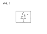
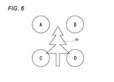
図5は、被写体としての木49を示している。図4の紙面の手前側に撮影者の目が存在し、各組の4画素を通して被写体の木49を見た場合、図6に示す様に、画素Aは木49を左斜め上(視点A)から見た画像データを取得し、画素Bは木49を右斜め上(視点B)から見た画像データを取得し、画素Cは木49を左斜め下(視点C)から見た画像データを取得し、画素Dは木49を右斜め下(視点D)から見た画像データを取得することになる。
FIG. 5 shows a
図7(a)(b)(c)(d)は、図6で説明した視点A,B,C,Dから見た画像データの具体例である。各組の画素Aから出力された撮像画像信号を信号処理部21が画像処理して得た撮像画像データ(図7(a))を記録メディア28に保存し、各組の画素Bから出力された撮像画像信号を信号処理部21が画像処理して得た撮像画像データ(図7(b))を記録メディア28に保存し、各組の画素Cから出力された撮像画像信号を信号処理部21が画像処理して得た撮像画像データ(図7(c))を記録メディア28に保存し、各組の画素Dから出力された撮像画像信号を信号処理部21が画像処理して得た撮像画像データ(図7(d))を記録メディア28に保存する。
7A, 7B, 7C, and 7D are specific examples of image data viewed from the viewpoints A, B, C, and D described with reference to FIG. Captured image data (FIG. 7A) obtained by image processing of the captured image signal output from each set of pixels A by the
これら図7(a)〜(d)の木49の4枚の撮像画像データは、マルチピクチャーフォーマットとして関連付けを行って記録メディア28に保存する。なお、記録される撮像画像データは、静止画像であっても、動画像であっても良い。
These four captured image data of the
この様に、各視点A,B,C,Dから撮影されマルチピクチャーフォーマットで記録メディア28に保存された撮像画像データを、3D画像表示を行える立体画像表示装置で観賞する場合、記録メディア28を立体画像表示装置に装着し、閲覧者が立体画像を観賞することになる。
In this way, when viewing captured image data taken from the viewpoints A, B, C, and D and stored in the
図8は、本発明の一実施形態に係る立体画像表示装置の機能ブロック構成図である。この立体画像表示装置50は、バス51に接続されたCPU52と、画像選択部53と、閲覧者の姿勢(右眼の視点と左眼の視点とが並ぶ方向)を検出する視点検出部54と、図2で説明した3D画像信号処理部33と同じ機能を持つ3D画像信号処理部55と、画像信号処理部56と、ROM57と、RAM58と、スピーカ60及びマイク61が接続された音声入出力処理部61と、立体画像撮像装置10から取り出した記録メディア28を装着するメディア読出制御部62と、3D画像を表示する表示部65が接続されたビデオエンコーダ66と、3D画像の表示方式によっては必要となる偏光メガネ等の閲覧者の視聴補助具67が接続される補助具制御部68とが接続される。CPU52には、操作部69や電源70が接続される。表示部65は、縦向き/横向きの両方で立体画像を表示できる特許文献6に記載される様な表示部を用いる。
FIG. 8 is a functional block configuration diagram of a stereoscopic image display apparatus according to an embodiment of the present invention. The stereoscopic
縦向き/横向きの両方で立体画像を表示できる表示部は、通常はテレビジョン装置の様な矩形の枠体内に填め込まれ、矩形の上縁が水平となるように部屋内に設置されるのが普通である。この結果、この「水平」と上記の縦向き/横向きの「縦向き」とが直交することになる。以下の説明では、この枠体の上縁に沿う方向を表示部の水平方向とし、これを基準として説明する。即ち、閲覧者が地面に対して直立に立っている時に左右の眼を結ぶ線が地面に対して水平になるので、その状態の閲覧者に立体視できる画像が提供される様に表示部を設置したときの横方向を「表示部の水平方向」と呼ぶことにする(例えば、特許文献6の表示部を用いた場合、縦向き(縦置き)の場合は同文献の図4のA方向で、横向き(横置き)の場合は同文献の図5のBの方向とする。)。 A display unit that can display stereoscopic images in both portrait and landscape orientations is usually placed in a rectangular frame like a television device and installed in the room so that the upper edge of the rectangle is horizontal. Is normal. As a result, the “horizontal” and the vertical / horizontal “vertical” are orthogonal to each other. In the following description, the direction along the upper edge of the frame will be referred to as the horizontal direction of the display unit, and this will be described as a reference. That is, when the viewer is standing upright with respect to the ground, the line connecting the left and right eyes is horizontal with respect to the ground, so the display unit is provided so that an image that can be viewed stereoscopically is provided to the viewer in that state. The horizontal direction when installed is referred to as the “horizontal direction of the display unit” (for example, when the display unit of Patent Document 6 is used, in the case of portrait orientation (vertical placement), the direction A in FIG. In the case of landscape orientation (horizontal orientation), the direction of FIG.
立体画像表示装置50の視点検出部54は、表示部の上記水平方向に対する視点の相対的な傾きを検出する。例えば、上記の枠体上縁部にカメラを備え、カメラが閲覧者の顔又は眼などの顔部位を検出し、閲覧者の左右の眼を結ぶ線と表示部の水平方向との相対的な傾きを検出する。また、立体表示方式が、偏光方式、液晶シャッタによるフィールドシーケンシャル方式等眼鏡を装着する場合、眼鏡に設けられた姿勢検出部により表示部に対する視点の傾きを検出しても良い。
The
記録メディア28が立体画像表示装置50に装着され、操作部69から観賞対象とする画像が選択されたとき、画像選択部53は、記録メディア28から表示に必要となる立体画像データを、閲覧者の検出視点に基づいて読み出す。なお、実施形態では、立体画像表示装置50が記録メディア28を介して画像データを読み込む構成としているが、勿論、ネットワーク等の信号線を介して画像データを読み込む構成でも良い。
When the
この立体画像データは、通常はJPEG形式やMPEG形式等の圧縮形態で記録されているため、画像信号処理部56はこの圧縮データを伸張して3D画像信号処理部55に転送する。3D画像信号処理部55は、閲覧者の視点に基づき、後述する様に組み合わせる立体画像データをビデオエンコーダ66に渡し、立体画像を3D画像表示部65に表示する。
Since the stereoscopic image data is normally recorded in a compressed form such as JPEG format or MPEG format, the image
図9は、立体画像を表示するときに組み合わせる(合成する)画像データの説明図であり、図10は、図9と同じ図であるが、実際の木49の画像を使って組み合わせる画像の具体例を示している。図11は、画像の組合せ合成の処理手順を示すフローチャートである。
FIG. 9 is an explanatory diagram of image data to be combined (combined) when displaying a stereoscopic image, and FIG. 10 is the same diagram as FIG. 9, but is a specific example of an image to be combined using an
記録メディア28には、図7(a)(b)(c)(d)に示す4視点から見た画像データA,B,C,Dが記録されている。閲覧者の姿勢を判定し(ステップS1)、この判定結果により左右の眼が表示部の水平方向に対して相対的に水平方向に近い(水平方向に対する角度が所定閾値(例えば45度)より小さい)場合(判定結果がYes)には、ステップS2に進み、水平方向の視差画像を選択する。具体的には、視点Aの画像と視点Cの画像を加算合成してA+Cの画像を生成し、これを左眼表示用の画像とする。また、視点Bの画像と視点Dの画像を加算合成してB+Dの画像を生成し、これを右眼表示用の画像とし、次のステップS3で、これらの画像を表示部65に表示する。
On the
ステップS1の判定の結果が否定(水平方向でなく、左右の眼が表示部の水平方向に対して相対的に垂直方向に近い)の場合には、次にステップS4に進み、閲覧者の姿勢により右眼の検出位置が左眼の検出位置よりも下側になっているか否かを判定する。この判定結果が肯定(Yes)の場合には、ステップS5に進み、右眼が下となる視差画像を選択する。つまり、視点Aの画像と視点Bの画像を加算合成してA+Bの画像を生成し、これを左眼表示用の画像とする。そして、視点Cの画像と視点Dの画像を加算合成してC+Dの画像を生成し、これを右眼表示用の画像とし、ステップS3に進んでこれら画像を表示部65に表示する。
If the result of the determination in step S1 is negative (not in the horizontal direction, the left and right eyes are relatively close to the vertical direction relative to the horizontal direction of the display unit), the process proceeds to step S4, and the viewer's posture Thus, it is determined whether or not the detection position of the right eye is below the detection position of the left eye. If the determination result is affirmative (Yes), the process proceeds to step S5, and a parallax image with the right eye down is selected. That is, the image of viewpoint A and the image of viewpoint B are added and synthesized to generate an A + B image, which is used as an image for left eye display. Then, the image of viewpoint C and the image of viewpoint D are added and synthesized to generate a C + D image, which is used as a right-eye display image, and the process proceeds to step S3 where these images are displayed on the
ステップS4の判定の結果が否定の場合には、左眼の検出位置が右眼の検出位置よりも下側であると判断してステップS6に進み、左眼が下となる視差画像を選択する。即ち、視点Cの画像と視点Dの画像を加算合成してC+Dの画像を生成し、これを左眼表示用の画像とする。そして、視点Aの画像と視点Bの画像を加算合成してA+Bの画像を生成し、これを右眼表示用の画像とし、ステップS3に進んでこれら画像を表示部65に表示する。
If the determination result in step S4 is negative, it is determined that the left eye detection position is below the right eye detection position, and the process proceeds to step S6 to select a parallax image with the left eye below. . That is, an image of viewpoint C and an image of viewpoint D are added and combined to generate a C + D image, which is used as an image for left eye display. Then, the image of the viewpoint A and the image of the viewpoint B are added and synthesized to generate an A + B image, which is used as an image for right eye display, and the process proceeds to step S3 to display these images on the
ステップS1,S2,S3,S4,S5,S6の処理を、所定時間毎に繰り返し行うことで、閲覧者の姿勢が途中で切り替わった場合でも、例えば視聴の途中で寝そべった姿勢に変化した場合でも、閲覧者は継続して立体画像を観賞することができる。しかも、本実施形態では、ステップS4を設け、右眼が下か左眼が下かを判断しているため、同じ傾きでも右眼用画像と左眼用画像とを逆に間違って表示することがなくなる。 Even if the viewer's posture is changed halfway by repeating the processes of steps S1, S2, S3, S4, S5, and S6 every predetermined time, for example, when the posture changes to a lying posture during viewing. The viewer can continuously view the stereoscopic image. Moreover, in the present embodiment, step S4 is provided, and it is determined whether the right eye is down or the left eye is down, so that the right eye image and the left eye image are erroneously displayed in reverse even with the same tilt. Disappears.
なお、図9〜図11では、斜め45度の立体画像については説明を省略したが、図6から明らかなように、視点Aの画像を左眼用,視点Dの画像を右眼用とすれば、右斜め45度に傾いた立体画像データを表示でき、視点Cの画像を左眼用,視点Bの画像を右眼用とすれば、左斜め45度に傾いた立体画像データを表示できる。 In FIGS. 9 to 11, the description of the oblique 45-degree stereoscopic image is omitted, but as is clear from FIG. 6, the viewpoint A image is for the left eye and the viewpoint D image is for the right eye. For example, stereoscopic image data tilted 45 degrees to the right can be displayed. If the image of viewpoint C is for the left eye and the image of viewpoint B is for the right eye, stereoscopic image data tilted 45 degrees to the left can be displayed. .
図12は、図3とは異なる画素配列の撮像素子80の表面模式図である。この例ではCCD型イメージセンサであるが、CMOS型イメージセンサでも良いことは図3の実施形態と同様である。
FIG. 12 is a schematic view of the surface of an
本実施形態の撮像素子80では、奇数行の画素行に対して偶数行の画素行が1/2画素ピッチづつずらして配列されており、各画素列に沿って形成される垂直電荷転送路(VCCD)42が、各画素41を避けるように蛇行して設けられている点が図3と異なるだけであるため、図3と同一部材には同一符号を付してその説明は省略する。
In the
本実施形態の撮像素子80でも4画素1組として同一色のカラーフィルタが積層されている。本実施形態の1組を構成する最隣接4画素の画素配列は、図13に示す様に4画素で構成される正方形を菱形状に配置して配列した構成となっており、1組毎に1つのマイクロレンズ47と同色カラーフィルタが積層される。菱形状配列の左角に設けられる画素Aと、上角に設けられる画素Bと、下角に設けられる画素Cと、右角に設けられる画素Dとが1つのマイクロレンズ下に設けられることで、瞳分割が行われる。
In the
図14は、木49の画像を画素A〜Dを通して見たときの視点位置A〜Dを示す図である。視点A(画素A)は被写体49を若干左側から見ることになり、視点B(画素B)は被写体49を若干上側から見ることになり、視点C(画素C)は被写体49を若干下側から見ることになり、視点D(画素D)は被写体49を若干右側から見ることになる。
FIG. 14 is a diagram illustrating viewpoint positions A to D when an image of the
図3の撮像素子14と図12の撮像素子80が画素数同一でチップサイズも同一とすると、図13の撮像素子80の水平方向(画素A―画素D間)の視差が、図4の撮像素子14の水平方向(画素A―画素B間)の視差より広くとれ、立体画像のデータとして有利となる。
If the
図15(a)(b)(c)(d)は、図14で説明した視点A,B,C,Dから見た画像データの具体例である。各組の画素Aで撮像された木49の撮像画像データ(図15(a))を図2の記録メディア28にマルチピクチャーフォーマット(以下、同様)で保存し、各組の画素Bで撮像された木49の撮像画像データ(図15(b))を記録メディア28に保存し、各組の画素Cで撮像された木49の撮像画像データ(図15(c))を記録メディア28に保存し、各組の画素Dで撮像された木49の撮像画像データ(図15(d))を記録メディア28に保存する。
FIGS. 15A, 15B, 15C, and 15D are specific examples of image data viewed from the viewpoints A, B, C, and D described in FIG. The captured image data (FIG. 15A) of the
図16は、図15(a)〜(d)の画像データを保存した記録メディア28から撮像画像データを読み出して立体画像を表示する立体画像表示装置50における処理手順を示すフローチャートであり、図17は、図16のフローチャートに従って選択された画像データを示す図である。
FIG. 16 is a flowchart showing a processing procedure in the stereoscopic
先ず、ステップS11で、表示部の水平方向に対する閲覧者の視点の相対的な傾きを検出し、傾きの方向が水平に近い(水平方向に対する角度が所定閾値(例えば45度)より小さい)場合(判定結果がYes)にはステップS12に進み、左眼表示用の画像として画素Aで撮像した画像データAを選択すると共に右眼表示用の画像として画素Dで撮像した画像データDを選択し、次のステップS13でこれら画像データA,Dを立体表示画面に表示する。 First, in step S11, the relative inclination of the viewer's viewpoint with respect to the horizontal direction of the display unit is detected, and the direction of the inclination is close to the horizontal (the angle with respect to the horizontal direction is smaller than a predetermined threshold (for example, 45 degrees)) ( When the determination result is Yes), the process proceeds to step S12, where the image data A captured by the pixel A is selected as the left-eye display image and the image data D captured by the pixel D is selected as the right-eye display image. In the next step S13, these image data A and D are displayed on the stereoscopic display screen.
ステップS11の判定の結果、傾きの方向が水平に近くない場合(垂直に近い場合で、判定結果がNo)には、次にステップS14に進み、その傾きが垂直方向で右眼の検出位置が左眼の検出位置よりが下側であるか否かを判定する。判定結果が肯定(Yes)であり右眼が下側の場合にはステップS15に進み、左眼表示用の画像として画像データBを選択すると共に右眼表示用画像として画像データCを選択し、ステップS13に進み、画像データB,Cを立体画像として表示する。 If the result of determination in step S11 is that the tilt direction is not nearly horizontal (when it is close to vertical and the determination result is No), the process proceeds to step S14, where the tilt is in the vertical direction and the detection position of the right eye is It is determined whether or not the detection position of the left eye is below. If the determination result is affirmative (Yes) and the right eye is on the lower side, the process proceeds to step S15, where the image data B is selected as the left-eye display image and the image data C is selected as the right-eye display image. In step S13, the image data B and C are displayed as a stereoscopic image.
ステップS14の判定の結果、否定(No)の場合、即ち、傾きの方向が垂直方向に近くて左眼が下側の場合には、ステップS16に進み、左眼表示用の画像として画像データCを選択すると共に右眼表示用の画像として画像データBを選択し、ステップS13でこれら画像データC,Bを立体画像として表示する。 If the result of determination in step S14 is negative (No), that is, if the direction of tilt is close to the vertical direction and the left eye is on the lower side, the process proceeds to step S16, and the image data C is displayed as an image for left eye display. And the image data B is selected as the right-eye display image, and the image data C and B are displayed as a stereoscopic image in step S13.
このステップS11〜S16の処理を所定時間毎に繰り返し行うことで、閲覧者の姿勢が途中で切り替わった場合でも、例えば視聴の途中で寝そべった姿勢に変化した場合でも、閲覧者は継続して立体画像を観賞することができる。しかも、本実施形態でもステップS14を設け、右眼が下か左眼が下かを判断しているため、同じ傾きでも右眼用画像と左眼用画像とを逆に間違って表示することがなくなる。 By repeatedly performing the processes of steps S11 to S16 every predetermined time, even when the viewer's posture is changed during the viewing, for example, when the posture changes to a lying-down posture during viewing, the viewer can continuously You can appreciate the images. Moreover, since step S14 is also provided in this embodiment and it is determined whether the right eye is down or the left eye is down, the right-eye image and the left-eye image can be erroneously displayed in reverse even with the same tilt. Disappear.
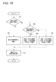
図16の処理では、説明を簡単に行うために、傾きの方向が斜めの場合を考慮していなかったが、図18に、傾きの方向が斜め方向の場合も含む処理手順を示す。図19は、図18の処理で選択される画像データを示す図である。 In the process of FIG. 16, for the sake of simplicity, the case where the inclination direction is oblique is not considered, but FIG. 18 shows a processing procedure including the case where the inclination direction is oblique. FIG. 19 is a diagram showing image data selected in the process of FIG.
図18のステップS21では、先ず、表示部の水平方向に対する閲覧者の視点の相対的な傾きが垂直、水平方向に比べて斜め方向に近いか否かを判定する。この判定の結果が否定の(No)の場合には、ステップS22に進み、図18で説明したステップS11,S12,S14,S15,S16の処理ステップで画像選択を行い、次にステップS13に進んで選択された画像データを表示する。 In step S21 of FIG. 18, first, it is determined whether or not the relative inclination of the viewer's viewpoint with respect to the horizontal direction of the display unit is closer to the diagonal direction than the vertical and horizontal directions. If the result of this determination is negative (No), the process proceeds to step S22, image selection is performed in the processing steps of steps S11, S12, S14, S15, and S16 described in FIG. 18, and then the process proceeds to step S13. The image data selected with is displayed.
ステップS21の判定の結果が肯定(Yes)の場合には次のステップS23に進み、右眼の検出位置が左眼の検出位置よりも下か否かを判定する。判定結果が肯定(Yes)の場合にはステップS24に進み、左眼表示用の画像として画像データAと画像データBを加算合成した画像A+Bを生成し、右眼表示用の画像として画像データCと画像データDを加算合成した画像C+Dを生成し、次のステップS13に進んで、画像A+Bと画像C+Dを画面に立体画像として表示する。 If the determination result of step S21 is affirmative (Yes), the process proceeds to the next step S23, and it is determined whether or not the detection position of the right eye is below the detection position of the left eye. If the determination result is affirmative (Yes), the process proceeds to step S24 to generate an image A + B obtained by adding and synthesizing the image data A and the image data B as an image for left eye display, and image data C as an image for right eye display. And image data D are added and synthesized, and the process proceeds to the next step S13, where the images A + B and C + D are displayed as a stereoscopic image on the screen.
ステップS23の判定の結果が否定(No)即ち、左眼の検出位置が下側で表示部の水平方向に対する閲覧者の視点の相対的な傾きが斜めの場合には、ステップS25に進み、左眼表示用の画像として画像データAと画像データCを加算合成した画像A+Cを生成し、右眼表示用の画像として画像データBと画像データDを加算合成した画像B+Dを生成し、次のステップS13に進み、画像A+Cと画像B+Dを画面に立体画像として表示する。 If the result of determination in step S23 is negative (No), that is, if the detection position of the left eye is lower and the relative tilt of the viewer's viewpoint with respect to the horizontal direction of the display unit is oblique, the process proceeds to step S25 and left Next, an image A + C obtained by adding and synthesizing image data A and image data C is generated as an image for eye display, and an image B + D obtained by adding and combining image data B and image data D is generated as an image for right eye display. Proceeding to S13, the images A + C and B + D are displayed on the screen as stereoscopic images.
この様に、斜め方向の視点にも対応可能にすると、更に細かい傾き方向の調整が可能となる。斜め方向にも容易に対処可能とする立体画像表示装置としては、視点の方向によらずに左右の分離が容易な眼鏡着用による偏光方式や、フィールドシーケンシャル方式等によるものが望ましい。 In this way, if it is possible to deal with an oblique viewpoint, it is possible to adjust the tilt direction more finely. As a stereoscopic image display device that can easily cope with an oblique direction, it is desirable to use a polarization method by wearing glasses, a field sequential method, or the like that can easily separate the left and right without depending on the direction of the viewpoint.
図20は、立体画像表示装置における全体の処理手順の基本を示すフローチャートである。立体画像表示装置50は、閲覧者の視点の方向を検出するが、この検出方法としては、前述したように、立体画像表示装置に装着したカメラ等で閲覧者の顔画像を撮影し、左右の目を結ぶ直線とその傾きを検出することで実現するのが、閲覧者側への負担が少なく好ましい。しかし、眼鏡着用による方式(偏光、フィールドシーケンシャル)の場合は、眼鏡に、ジャイロセンサ等により検出した傾き情報を送信させる機能を持たせても良い。
FIG. 20 is a flowchart showing the basics of the entire processing procedure in the stereoscopic image display apparatus. The stereoscopic
立体画像表示装置50は、先ず、ステップS31で、表示部の水平方向に対する閲覧者(視聴者)の視点の相対的な傾き及び方向を検出し、次のステップS32で、図16,図18で説明した画像選択の実施を行い、次のステップS33(=図18のステップS13)で左右の視差画像を画面に表示する。
First, in step S31, the stereoscopic
そして、次のステップS34では、立体画像の閲覧(観賞)が終了したか否かを判定し、終了してない場合にはステップS31に戻る。これにより、閲覧者が立体画像の閲覧中にその姿勢を変化させ、例えば寝そべって観賞する姿勢に変化しても、その姿勢変更に合わせた視差画像が選択,合成されて画面に表示されるため、閲覧者は姿勢を変化させても違和感なく立体画像の観賞を継続することができる。 In the next step S34, it is determined whether or not the viewing (viewing) of the stereoscopic image has ended. If not, the process returns to step S31. As a result, even when the viewer changes the posture while viewing the stereoscopic image, for example, the posture changes to a posture to lie down, the parallax image according to the posture change is selected, synthesized, and displayed on the screen. Even if the viewer changes his / her posture, the viewer can continue to view the stereoscopic image without a sense of incongruity.
上述した実施形態では、単眼式の立体画像撮像装置で撮影した4つの視点の撮像画像データを基に、立体視可能な左眼用,右眼用の画像を選択あるいは合成して画面に表示したが、立体画像撮像装置は単眼である必要はなく、画素A,B,C,Dに相当する撮影レンズ系及び撮像素子を4系統備えるものでもよい。 In the above-described embodiment, the left-eye and right-eye images that can be viewed stereoscopically are selected or combined and displayed on the screen based on the captured image data of the four viewpoints captured by the monocular stereoscopic image capturing device. However, the stereoscopic image capturing apparatus does not need to be monocular, and may include four systems of photographing lens systems and image sensors corresponding to the pixels A, B, C, and D.
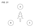
あるいは、3眼の撮像装置でもよく、単眼で3つの視点の画像データを得て、複数の視点方向の画像を合成することも可能である。例えば、図21に示す様に、被写体を中心に正三角形を成す視点A,B,Cの画像を撮像することができれば、画像Bと画像Cとで水平方向の視差画像を得ることができ、画像Aと画像(B+C)/2とで垂直方向の視差画像を得ることができ、画像Bと画像(A+C)/2とで斜め30度に傾斜した視差画像を得ることができ、画像Aと画像Bとで斜め60度に傾斜した視差画像を得ることができる。なお、図21に限ることなく、正三角形を逆三角形として各視点を配置しても良い。 Alternatively, a three-lens imaging device may be used, and it is possible to obtain image data of three viewpoints with a single eye and synthesize images of a plurality of viewpoint directions. For example, as shown in FIG. 21, if images of viewpoints A, B, and C that form an equilateral triangle with the subject as the center can be captured, a parallax image in the horizontal direction can be obtained between the images B and C, A parallax image in the vertical direction can be obtained from the image A and the image (B + C) / 2, and a parallax image inclined by 30 degrees can be obtained from the image B and the image (A + C) / 2. A parallax image tilted at an angle of 60 degrees with the image B can be obtained. Note that the viewpoint is not limited to that shown in FIG.
3視点の場合には、上記の様に、垂直,水平,右30度,右60度,左30度,左60度の各視差画像を合成できるため、閲覧者の姿勢がこれらの(表示部の水平方向に対する視点の相対的な)傾き方向に全く一致していなくても、これら視差画像の中で最も立体視可能な視差画像を合成することになる。これは4視点の場合も同様である。 In the case of three viewpoints, as described above, since the parallax images of vertical, horizontal, right 30 degrees, right 60 degrees, left 30 degrees, and left 60 degrees can be synthesized, The parallax images that are most stereoscopically viewable among these parallax images are synthesized even if they do not coincide with the tilt direction of the viewpoint relative to the horizontal direction. The same applies to the case of four viewpoints.
以上述べた実施形態では、閲覧者が一人の場合を想定しているが、閲覧者が複数存在した場合には、各人が立体画像を観賞できる様にするのが好ましい。 In the embodiment described above, it is assumed that there is only one viewer. However, when there are a plurality of viewers, it is preferable that each person can view a stereoscopic image.
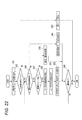
図22は、複数の閲覧者に対応できる処理手順を示すフローチャートである。先ず、記録メディア28から表示用データを読み込み(ステップS41)、立体画像表示用のデータがあるか否かを判定する(ステップS42)。立体画像表示用のデータが記録メディア28内になく、2D画像(平面画像)のデータしか無い場合にはステップS43に進み、2D画像データを表示してこの処理を終了する。
FIG. 22 is a flowchart illustrating a processing procedure that can handle a plurality of viewers. First, display data is read from the recording medium 28 (step S41), and it is determined whether there is stereoscopic image display data (step S42). If there is no stereoscopic image display data in the
ステップS42の判定の結果、立体画像の表示用データが存在する場合には、次に、その立体画像の表示用データが複数の視点情報として存在するか否かを判定する(ステップS44)。即ち、図14の視点A,B,C,Dの立体画像のデータとして存在するか(或いは図21の始点A,B,Cの立体画像のデータとして存在するか)判定する。 If there is stereoscopic image display data as a result of the determination in step S42, it is next determined whether or not the stereoscopic image display data exists as a plurality of viewpoint information (step S44). That is, it is determined whether the data exists as the stereoscopic image data of the viewpoints A, B, C, and D in FIG. 14 (or exists as the stereoscopic image data of the start points A, B, and C in FIG. 21).
少なくとも3点以上の視点による立体画像のデータが存在しない場合(2点の視点情報しかない場合)には、ステップS44からステップ45に進み、その2点の視点による立体画像データを表示し、視聴が終了したか否かを判定し(ステップS46)、視聴が終了した場合にはこの処理を終了し、視聴が終了していない場合にはステップS46からステップ44に戻る。 When there is no stereoscopic image data with at least three or more viewpoints (when there is only two viewpoint information), the process proceeds from step S44 to step 45, where the stereoscopic image data with the two viewpoints is displayed and viewed. (Step S46), the process ends when viewing ends, and the process returns from step S46 to step 44 when viewing ends.
ステップS44の判定の結果、少なくとも3点以上の視点による立体画像のデータが存在する場合には、ステップS44からステップS47に進み、閲覧者が複数存在するか否かを判定する。閲覧者が単数の場合には、ステップS48に進み、図16又は図18の処理を行い、ステップS46に進む。 As a result of the determination in step S44, if there is data of a stereoscopic image from at least three viewpoints, the process proceeds from step S44 to step S47, and it is determined whether there are a plurality of viewers. If there is a single viewer, the process proceeds to step S48, the process of FIG. 16 or 18 is performed, and the process proceeds to step S46.
ステップS47の判定の結果、複数の閲覧者が存在する場合には、ステップS50に進み、各閲覧者の姿勢をカメラ映像等から夫々算出する。そして、次のステップS51で、複数の閲覧者の平均的姿勢(平均的傾き方向)を算出し、平均的視差画像を合成して画面に表示し(ステップS52)、ステップS46に進む。 If the result of determination in step S47 is that there are a plurality of viewers, the process proceeds to step S50, and the posture of each viewer is calculated from the camera video or the like. In the next step S51, the average posture (average tilt direction) of a plurality of viewers is calculated, the average parallax image is synthesized and displayed on the screen (step S52), and the process proceeds to step S46.
この様に、複数閲覧者の平均的傾き方向の画像を合成して表示するため、各人が夫々の姿勢で立体画像を観賞することが可能となる。 In this way, since the images in the average inclination direction of a plurality of viewers are combined and displayed, it is possible for each person to view the stereoscopic image in their respective postures.
図23は、図22の処理手順によって表示する視点情報の変化を示す図である。第1,第2のユーザ(閲覧者)は最初は水平方向の姿勢を保って画面を見ているが、第2ユーザ(閲覧者)が途中で横に寝転がって画面を視聴し(傾き方向が垂直方向)、次にまた起きあがって画面を視聴したとする。 FIG. 23 is a diagram showing changes in the viewpoint information displayed by the processing procedure of FIG. The first and second users (viewers) initially look at the screen while maintaining a horizontal orientation, but the second user (viewers) lie down on the way and watch the screen (the tilt direction is (Vertical direction), then wake up again and watch the screen.
最初は水平方向の視差画像とするために、図14に示す視点Aの画像を左眼用として表示すると共に視点Dの画像を右眼用として表示しているが、途中で第2閲覧者の姿勢が変わったため、第1,第2の閲覧者の姿勢の平均値に基づき、斜め45度となる視点Aの画像を左眼用として表示すると共に視点Bの画像を右眼用として表示する。これにより、第2閲覧者が姿勢を変化させても第1,第2の閲覧者共に立体画像を視聴し続けることが可能となる。 At first, in order to obtain a horizontal parallax image, the image of viewpoint A shown in FIG. 14 is displayed for the left eye and the image of viewpoint D is displayed for the right eye. Since the posture has changed, based on the average value of the postures of the first and second viewers, the image of the viewpoint A that is 45 degrees obliquely is displayed for the left eye and the image of the viewpoint B is displayed for the right eye. Thereby, even if the second viewer changes the posture, the first and second viewers can continue to view the stereoscopic image.
なお、この実施形態の場合、その姿勢により立体表示ができない閲覧者が発生することもある。このときは、その閲覧者に対してガイド表示などを行い、立体表示可能な姿勢をとるように通知しても良い。 In the case of this embodiment, a viewer who cannot perform stereoscopic display may occur depending on the posture. At this time, a guide display or the like may be given to the viewer so as to notify the viewer of a posture capable of stereoscopic display.
図24は、別実施形態に係る複数閲覧者に対応する処理手順を示すフローチャートである。本実施形態は、図22の実施形態と、ステップS50,S51,S52が異なるだけであり、これらに代わるステップS50a,S51a,S52aについてだけ説明する。 FIG. 24 is a flowchart illustrating a processing procedure corresponding to a plurality of viewers according to another embodiment. This embodiment is different from the embodiment of FIG. 22 only in steps S50, S51, and S52, and only steps S50a, S51a, and S52a that replace them will be described.
複数の閲覧者が存在する場合に進むステップS50aでは、各視点データA,B,C,Dをフレームシーケンシャル駆動する。そして、次のステップS51aでは、閲覧者の夫々の視聴姿勢を検出し、次のステップS52aでは、各人の視聴姿勢に応じて視聴用機器へタイミング信号を発信し、ステップS46に進む。 In step S50a that proceeds when there are a plurality of viewers, each viewpoint data A, B, C, and D is frame-sequentially driven. In the next step S51a, the viewing posture of each viewer is detected. In the next step S52a, a timing signal is transmitted to the viewing device according to the viewing posture of each person, and the process proceeds to step S46.
図25は、図24の処理手順によって表示する情報変化を示す図である。ステップS50aにより、巡回的に、視点A→視点B→視点C→視点D→視点A→…とシーケンシャルに各視点データ(画像データ)が立体画像表示装置50の画面に切換表示されている(図25の左端)。この画面を見る第1,第2閲覧者は、アクティブシャッタメガネ等の視聴用装着器具を掛けており、立体画像表示装置50はこの視聴用装着器具に制御信号を発信し、夫々の閲覧者姿勢に応じたタイミングで、メガネのシャッタ開閉制御を閲覧者毎に別個に行う。
FIG. 25 is a diagram showing a change in information displayed by the processing procedure of FIG. By step S50a, each viewpoint data (image data) is cyclically switched and displayed on the screen of the stereoscopic
第1閲覧者の姿勢は、最初、その傾き方向が垂直方向となるように寝そべった姿勢で画面を視聴しており、途中で起きあがってその傾き方向を水平としている。このとき、傾き方向が垂直のときは視点Cの画像を左眼用に、視点Bの画像を右眼用に表示させるため、視点Cの画像が表示されているタイミングで第1閲覧者のメガネの左眼のシャッタを「開」とし、視点Bの画像が画面に表示されているタイミングで第1閲覧者のメガネの右眼のシャッタを「開」とする。 As for the first viewer's posture, the user views the screen in such a manner that the tilt direction is the vertical direction at first, and wakes up halfway to make the tilt direction horizontal. At this time, when the tilt direction is vertical, the image of the viewpoint C is displayed for the left eye and the image of the viewpoint B is displayed for the right eye. Therefore, the glasses of the first viewer are displayed at the timing when the image of the viewpoint C is displayed. The left-eye shutter of the first viewer is set to “open”, and the right-eye shutter of the first viewer's glasses is set to “open” at the timing when the image of the viewpoint B is displayed on the screen.
第1閲覧者が姿勢を変化させ傾き方向が水平となったときは、視点Aの画像が表示されているタイミングで第1閲覧者のメガネの左眼のシャッタを「開」とし、視点Dの画像が画面に表示されているタイミングで第1閲覧者のメガネの右眼のシャッタを「開」とする。これにより、第1閲覧者は、姿勢を変化させても常に立体画像を観賞することができる。 When the first viewer changes posture and the tilt direction becomes horizontal, the shutter of the left eye of the first viewer's glasses is set to “open” at the timing when the image of the viewpoint A is displayed, and the viewpoint D The shutter of the right eye of the first viewer's glasses is set to “open” at the timing when the image is displayed on the screen. Thereby, even if a 1st browsing person changes an attitude | position, he can always appreciate a stereo image.
第2閲覧者の場合も第1閲覧者と同様に、該当する視点情報が画面に表示されているタイミングで、第2閲覧者の左右のシャッタを開とすることで、途中で姿勢を変化させても常に立体画像を観賞することが可能となる。 Similarly to the first viewer, the second viewer can change the posture in the middle by opening the left and right shutters of the second viewer at the timing when the corresponding viewpoint information is displayed on the screen. However, it is always possible to view stereoscopic images.
このアクティブシャッタ方式の場合、目の残像を利用しているため、例えば、上述した画像合成(A+B)を行うとき視点Aの情報が表示されているタイミングと視点Bの情報が表示されているタイミングの両方でシャッタを「開」とすれば、目の残像上で画像合成を行うことが可能となる。 In the case of this active shutter method, since an afterimage of the eye is used, for example, the timing at which the information on the viewpoint A is displayed and the timing at which the information on the viewpoint B is displayed when performing the above-described image composition (A + B). If the shutter is “open” in both cases, it is possible to perform image composition on the afterimage of the eye.
本実施形態の場合、どの閲覧者の視聴姿勢にも当てはまらない視点データの駆動期間を、他の視点データに割り当てても良い。その場合、各視点データ毎の表示時間の差による輝度差や画面のちらつきを防止するため、均等に割り当てるのが良い。また、どの閲覧者の視聴姿勢にも当てはまらない視点データの駆動期間を、黒データの表示に割り当て、残像によるクロストークを軽減する等してもよい。 In the case of this embodiment, a viewpoint data driving period that does not apply to any viewer's viewing posture may be assigned to other viewpoint data. In such a case, it is preferable to assign them evenly in order to prevent a luminance difference or a screen flicker due to a difference in display time for each viewpoint data. In addition, a viewpoint data driving period that does not apply to any viewer's viewing posture may be assigned to the display of black data to reduce crosstalk due to afterimages.
本実施形態によれば、複数の閲覧者が異なる視聴姿勢で同じ画面を見ていても、各閲覧者の視聴姿勢に夫々対応した正しい立体映像を観賞させることが可能となり、より気楽で簡単に立体映像を視聴させることができる。 According to the present embodiment, even when a plurality of viewers are viewing the same screen in different viewing postures, it is possible to view the correct stereoscopic video corresponding to each viewer's viewing posture, making it easier and easier 3D images can be viewed.
以上述べた様に、実施形態の立体画像表示装置及びその方法は、平面をなす3つ以上の異なる視点から被写体を撮像した画像データを記憶手段に記憶し、前記記憶手段に記憶された該画像データに基づいて、左眼用画像と右眼用画像を表示部が表示し、該表示部を閲覧する閲覧者の左右の眼を結ぶ線と該表示部との相対的な傾きを視点検出部が検出し、該相対的な傾きに基づいて、該画像データから左眼用画像と右眼用画像を表示制御部が生成することを特徴とする。 As described above, the stereoscopic image display apparatus and method according to the embodiment store in the storage means image data obtained by imaging the subject from three or more different viewpoints forming a plane, and the image stored in the storage means Based on the data, the display unit displays the image for the left eye and the image for the right eye, and the viewpoint detection unit detects the relative inclination between the line connecting the left and right eyes of the viewer who browses the display unit and the display unit And a display control unit generates a left-eye image and a right-eye image from the image data based on the relative inclination.
また、実施形態の立体画像表示装置及びその方法は、前記記憶された画像データは被写体に対し4つの異なる視点から撮像された画像データであり、前記相対的な傾きと同じ向きの画像データが前記記憶された画像データ中に有るか無いかを判定手段が判定し、前記表示制御部は、該判定手段の結果に応じて、前記記憶された画像データから左眼用画像と右眼用画像を生成することを特徴とする。 In the stereoscopic image display apparatus and method according to the embodiment, the stored image data is image data captured from four different viewpoints with respect to the subject, and the image data having the same orientation as the relative inclination is the image data. The determination unit determines whether or not the stored image data is present, and the display control unit determines the left-eye image and the right-eye image from the stored image data according to a result of the determination unit. It is characterized by generating.
また、実施形態の立体画像表示装置及びその方法の前記表示制御部は、前記判定手段が画像データ有りと判定したときは、前記記憶された画像データから左眼用画像と右眼用画像を選択し、該判定手段が画像データ無しと判定したとき、前記記憶された画像データを合成して前記視点の向きに合わせた左眼用画像と右眼用画像を生成することを特徴とする。 Further, the display control unit of the stereoscopic image display apparatus and method according to the embodiment selects a left-eye image and a right-eye image from the stored image data when the determination unit determines that there is image data. When the determination unit determines that there is no image data, the stored image data is combined to generate a left-eye image and a right-eye image that match the orientation of the viewpoint.
また、実施形態の立体画像表示装置及びその方法の前記判定手段は、前記同じ向きの画像データが有るか無いかの判定を、前記相対的な傾きに対する角度が所定閾値未満の画像データが有るか無いかで判定することを特徴とする。 Further, the determination means of the stereoscopic image display apparatus and method according to the embodiment determines whether or not there is image data in the same direction, whether or not there is image data whose angle with respect to the relative inclination is less than a predetermined threshold. It is characterized by judging whether there is no.
また、実施形態の立体画像表示装置及びその方法は、前記視点検出部が検出した前記閲覧者の右眼が左眼より下側にあるか否かに応じて前記表示制御部は前記左眼用画像と前記右眼用画像を生成することを特徴とする。 Further, in the stereoscopic image display apparatus and method according to the embodiment, the display control unit may be configured for the left eye according to whether or not the viewer's right eye detected by the viewpoint detection unit is below the left eye. An image and the right-eye image are generated.
また、実施形態の立体画像表示装置及びその方法の前記表示制御部は、前記視点検出部が前記相対的な傾きの変化を検出したとき、該相対的な傾きの変化に応じて左眼用画像と右眼用画像を生成することを特徴とする。 Further, the display control unit of the stereoscopic image display apparatus and method according to the embodiment may be configured such that when the viewpoint detection unit detects a change in the relative inclination, the left-eye image according to the change in the relative inclination. And generating an image for the right eye.
また、実施形態の立体画像表示装置及びその方法は、前記視点検出部が前記閲覧者として複数人の前記相対的な傾きを検出したとき、該複数人の前記相対的な傾きの平均値を平均値視点検出手段が求め、前記表示制御部は、該平均値に合わせて左眼用画像と右眼用画像を生成することを特徴とする。 Further, in the stereoscopic image display apparatus and method according to the embodiment, when the viewpoint detection unit detects the relative inclinations of a plurality of persons as the viewer, the average value of the relative inclinations of the plurality of persons is averaged. Obtained by the value viewpoint detection means, the display control unit generates a left-eye image and a right-eye image in accordance with the average value.
また、実施形態の立体画像表示装置及びその方法の前記表示制御部は、前記視点検出部が前記複数人の前記相対的な傾きを検出したとき、前記記憶された画像データから前記複数人の該相対的な傾きに応じた左眼用画像と右眼用画像を生成し、該複数人の該相対的な傾きの順番に左眼用画像と右眼用画像を表示することを特徴とする。 In addition, the display control unit of the stereoscopic image display apparatus and method according to the embodiment, when the viewpoint detection unit detects the relative inclination of the plurality of persons, the plurality of persons A left-eye image and a right-eye image corresponding to the relative inclination are generated, and the left-eye image and the right-eye image are displayed in the order of the relative inclinations of the plurality of persons.
また、実施形態の立体画像表示装置及びその方法は、前記複数人の各々が掛けている複数の閲覧用保持具を備えた立体画像表示システムの立体画像表示装置及び方法であって、該複数の閲覧用保持具は、前記表示部の画像を前記複数人の各々の前記相対的な傾きに合わせて別々に制御することを特徴とする。 In addition, the stereoscopic image display apparatus and method according to the embodiment are a stereoscopic image display apparatus and method for a stereoscopic image display system including a plurality of browsing holders on which each of the plurality of persons is hung. The browsing holder controls the image of the display unit separately according to the relative inclination of each of the plurality of persons.
また、実施形態の立体画像表示装置及びその方法は、前記4つの視点が正方形に配置されることを特徴とする。 Further, the stereoscopic image display apparatus and method according to the embodiment are characterized in that the four viewpoints are arranged in a square.
また、実施形態の立体画像表示装置及びその方法は、前記4つの視点が前記被写体の左斜め上と右斜め上と左斜め下と右斜め下とに配置されることを特徴とする。 In addition, the stereoscopic image display apparatus and method according to the embodiment are characterized in that the four viewpoints are arranged on the upper left, upper right, lower left, and lower right of the subject.
また、実施形態の立体画像表示装置及びその方法は、前記4つの視点が前記被写体の上下左右に配置されることを特徴とする。 In addition, the stereoscopic image display apparatus and method according to the embodiment are characterized in that the four viewpoints are arranged on the top, bottom, left, and right of the subject.
以上述べた実施形態によれば、閲覧者が閲覧姿勢を変化させても変化前後で立体映像を継続して観賞でき、また、少ない立体映像データを用いて閲覧者の様々な姿勢に対応した立体画像を表示でき、更にまた、複数の閲覧者毎に適切な立体映像を表示することが可能となる。 According to the embodiment described above, even if the viewer changes the viewing posture, the stereoscopic video can be continuously viewed before and after the change, and the stereoscopic video corresponding to the various postures of the viewer using a small amount of stereoscopic video data. An image can be displayed, and an appropriate stereoscopic video can be displayed for each of a plurality of viewers.
本発明に係る立体画像表示方法及びその装置は、閲覧者(視聴者)が閲覧(視聴)中に姿勢を変化させても閲覧者は立体画像を観賞し続けることができるため、パーソナルコンピュータのモニタ装置やテレビジョン装置等の立体画像表示装置等に適用すると有用である。 The stereoscopic image display method and apparatus according to the present invention allow a viewer (viewer) to continue to view a stereoscopic image even when the viewer (viewer) changes his / her posture while browsing (viewing). The present invention is useful when applied to a stereoscopic image display device such as a device or a television device.
10 立体画像撮像装置
12 撮影レンズ
13 瞳分割光学系
14 撮像素子
20 CPU
21 画像処理装置
28 記録メディア
41 画素
42 垂直電荷転送路(VCCD)
47 マイクロレンズ
50 立体画像表示装置
52 CPU
53 画像選択部
54 視点検出部
55 3D画像信号処理部
65 3D画像表示部
DESCRIPTION OF
21
47
53
Claims (24)
前記記憶手段に記憶された該画像データに基づいて、左眼用画像と右眼用画像を表示する表示部と、
該表示部を閲覧する閲覧者の左右の眼を結ぶ線と該表示部との相対的な傾きを検出する視点検出部と、
該相対的な傾きに基づいて、該画像データから左眼用画像と右眼用画像を生成する表示制御部と
を備える立体画像表示装置。 Storage means for storing image data obtained by imaging a subject from three or more different viewpoints forming a plane;
A display unit for displaying a left-eye image and a right-eye image based on the image data stored in the storage unit;
A viewpoint detection unit that detects a relative inclination between a line connecting the left and right eyes of a viewer who browses the display unit and the display unit;
A stereoscopic image display device comprising: a display control unit that generates a left-eye image and a right-eye image from the image data based on the relative inclination.
前記記憶された画像データは被写体に対し4つの異なる視点から撮像された画像データであり、前記相対的な傾きに対し同じ向きの画像データが前記記憶された画像データ中に有るか無いかを判定する判定手段を更に備え、
前記表示制御部は、該判定手段の結果に応じて、該記憶された画像データから左眼用画像と右眼用画像を生成する
ことを特徴とする立体画像表示装置。 The stereoscopic image display device according to claim 1,
The stored image data is image data taken from four different viewpoints with respect to the subject, and it is determined whether or not there is image data in the same direction with respect to the relative inclination in the stored image data. Determining means for
The display control unit generates a left-eye image and a right-eye image from the stored image data according to the result of the determination unit.
前記表示制御部は、前記判定手段が画像データ有りと判定したときは、前記記憶された画像データから左眼用画像と右眼用画像を選択し、該判定手段が画像データ無しと判定したとき、前記記憶された画像データを合成して前記視点の向きに合わせた左眼用画像と右眼用画像を生成する
ことを特徴とする立体画像表示装置。 The stereoscopic image display device according to claim 1 or 2,
When the determination unit determines that there is image data, the display control unit selects a left-eye image and a right-eye image from the stored image data, and when the determination unit determines that there is no image data. A left-eye image and a right-eye image generated by synthesizing the stored image data to match the direction of the viewpoint are generated.
前記表示制御部は、前記視点検出部が前記相対的な傾きの変化を検出したとき、該相対的な傾きの変化に応じて左眼用画像と右眼用画像を生成することを特徴とする立体画像表示装置。 The stereoscopic image display device according to any one of claims 1 to 5,
The display control unit generates a left-eye image and a right-eye image according to the relative inclination change when the viewpoint detection unit detects the relative inclination change. Stereoscopic image display device.
前記視点検出部が前記閲覧者として複数人の前記相対的な傾きを検出したとき、該複数人の前記相対的な傾きの平均値を求める平均視点検出手段を更に備え、
前記表示制御部は、該平均値に合わせて左眼用画像と右眼用画像を生成する
ことを特徴とする立体画像表示装置。 The stereoscopic image display device according to any one of claims 1 to 6,
When the viewpoint detection unit detects the relative inclination of a plurality of persons as the viewer, the viewpoint detection unit further includes an average viewpoint detection unit that calculates an average value of the relative inclinations of the plurality of persons.
The display control unit generates a left-eye image and a right-eye image in accordance with the average value.
前記表示制御部は、前記視点検出部が前記複数人の前記相対的な傾きを検出したとき、前記記憶された画像データから前記複数人の該相対的な傾きに応じた左眼用画像と右眼用画像を生成し、該複数人の該相対的な傾きの順番に左眼用画像と右眼用画像を表示する
ことを特徴とする立体画像表示装置。 The stereoscopic image display device according to any one of claims 1 to 7,
The display control unit, when the viewpoint detection unit detects the relative inclination of the plurality of persons, from the stored image data, a left-eye image corresponding to the relative inclination of the plurality of persons and a right A stereoscopic image display device that generates an image for an eye and displays an image for a left eye and an image for a right eye in the order of the relative inclinations of the plurality of persons.
該複数の閲覧用保持具は、前記表示部の画像を前記複数人の各々の前記相対的な傾きに合わせて別々に制御する
ことを特徴とする立体画像表示システム。 A stereoscopic image display system comprising: the stereoscopic image display device according to claim 8; and a plurality of browsing holders on which each of the plurality of people is hung.
The plurality of browsing holders separately control the image on the display unit according to the relative inclination of each of the plurality of persons.
前記記憶手段に記憶された該画像データに基づいて、左眼用画像と右眼用画像を表示部が表示し、
該表示部を閲覧する閲覧者の左右の眼を結ぶ線と該表示部との相対的な傾きを視点検出部が検出し、
該相対的な傾きに基づいて、該画像データから左眼用画像と右眼用画像を表示制御部が生成する
立体画像表示方法。 Storing image data obtained by imaging a subject from three or more different viewpoints forming a plane in a storage means;
Based on the image data stored in the storage means, the display unit displays an image for the left eye and an image for the right eye,
The viewpoint detection unit detects a relative inclination between a line connecting the left and right eyes of a viewer who browses the display unit and the display unit,
A stereoscopic image display method in which a display control unit generates a left-eye image and a right-eye image from the image data based on the relative inclination.
前記記憶された画像データは被写体に対し4つの異なる視点から撮像された画像データであり、前記相対的な傾きと同じ向きの画像データが前記記憶された画像データ中に有るか無いかを判定手段が判定し、
前記表示制御部は、該判定手段の結果に応じて、前記記憶された画像データから左眼用画像と右眼用画像を生成する
ことを特徴とする立体画像表示方法。 The stereoscopic image display method according to claim 13,
The stored image data is image data taken from four different viewpoints with respect to the subject, and it is determined whether or not the stored image data has image data in the same direction as the relative inclination. Judgment,
The display control unit generates a left-eye image and a right-eye image from the stored image data according to the result of the determination unit.
前記表示制御部は、前記判定手段が画像データ有りと判定したときは、前記記憶された画像データから左眼用画像と右眼用画像を選択し、該判定手段が画像データ無しと判定したとき、前記記憶された画像データを合成して前記視点の向きに合わせた左眼用画像と右眼用画像を生成する
ことを特徴とする立体画像表示方法。 The stereoscopic image display method according to claim 13 or 14,
When the determination unit determines that there is image data, the display control unit selects a left-eye image and a right-eye image from the stored image data, and when the determination unit determines that there is no image data. A method for displaying a three-dimensional image, comprising: synthesizing the stored image data to generate a left-eye image and a right-eye image in accordance with the orientation of the viewpoint.
前記表示制御部は、前記視点検出部が前記相対的な傾きの変化を検出したとき、該相対的な傾きの変化に応じて左眼用画像と右眼用画像を生成することを特徴とする立体画像表示方法。 A stereoscopic image display method according to any one of claims 13 to 17,
The display control unit generates a left-eye image and a right-eye image according to the relative inclination change when the viewpoint detection unit detects the relative inclination change. 3D image display method.
前記視点検出部が前記閲覧者として複数人の前記相対的な傾きを検出したとき、該複数人の前記相対的な傾きの平均値を平均値視点検出手段が求め、
前記表示制御部は、該平均値に合わせて左眼用画像と右眼用画像を生成する
ことを特徴とする立体画像表示方法。 The stereoscopic image display method according to any one of claims 13 to 18,
When the viewpoint detection unit detects the relative inclination of a plurality of persons as the viewer, an average value viewpoint detection means obtains an average value of the relative inclinations of the plurality of persons,
The display control unit generates a left-eye image and a right-eye image in accordance with the average value.
前記表示制御部は、前記視点検出部が前記複数人の前記相対的な傾きを検出したとき、前記記憶された画像データから前記複数人の該相対的な傾きに応じた左眼用画像と右眼用画像を生成し、該複数人の該相対的な傾きの順番に左眼用画像と右眼用画像を表示する
ことを特徴とする立体画像表示方法。 The stereoscopic image display method according to any one of claims 13 to 19,
The display control unit, when the viewpoint detection unit detects the relative inclination of the plurality of persons, from the stored image data, a left-eye image corresponding to the relative inclination of the plurality of persons and a right A stereoscopic image display method comprising: generating an image for an eye and displaying an image for a left eye and an image for a right eye in the order of the relative inclinations of the plurality of persons.
該複数の閲覧用保持具は、前記表示部の画像を前記複数人の各々の前記相対的な傾きに合わせて別々に制御する
ことを特徴とする立体画像表示方法。 A stereoscopic image display method of a stereoscopic image display system comprising a plurality of browsing holders worn by each of the plurality of persons according to claim 20,
The three-dimensional image display method, wherein the plurality of browsing holders separately control images on the display unit according to the relative inclination of each of the plurality of persons.
Priority Applications (1)
| Application Number | Priority Date | Filing Date | Title |
|---|---|---|---|
| JP2010150574A JP2012015818A (en) | 2010-06-30 | 2010-06-30 | Three-dimensional image display device and display method |
Applications Claiming Priority (1)
| Application Number | Priority Date | Filing Date | Title |
|---|---|---|---|
| JP2010150574A JP2012015818A (en) | 2010-06-30 | 2010-06-30 | Three-dimensional image display device and display method |
Publications (2)
| Publication Number | Publication Date |
|---|---|
| JP2012015818A true JP2012015818A (en) | 2012-01-19 |
| JP2012015818A5 JP2012015818A5 (en) | 2013-02-14 |
Family
ID=45601715
Family Applications (1)
| Application Number | Title | Priority Date | Filing Date |
|---|---|---|---|
| JP2010150574A Withdrawn JP2012015818A (en) | 2010-06-30 | 2010-06-30 | Three-dimensional image display device and display method |
Country Status (1)
| Country | Link |
|---|---|
| JP (1) | JP2012015818A (en) |
Cited By (5)
| Publication number | Priority date | Publication date | Assignee | Title |
|---|---|---|---|---|
| JP2012255820A (en) * | 2011-06-07 | 2012-12-27 | Sharp Corp | Stereoscopic image displaying apparatus and stereoscopic image displaying method |
| CN103313065A (en) * | 2012-03-16 | 2013-09-18 | 索尼公司 | Image processing device and image processing method |
| WO2013136832A1 (en) * | 2012-03-13 | 2013-09-19 | 富士フイルム株式会社 | Stereoscopic image display control device and stereoscopic image display control method |
| JP2014072747A (en) * | 2012-09-28 | 2014-04-21 | Dainippon Printing Co Ltd | Stereoscopic display device and stereoscopic display system |
| JP2016202934A (en) * | 2016-06-28 | 2016-12-08 | ソニー株式会社 | Medical image processing device and endoscope system, medical image processing method and program |
-
2010
- 2010-06-30 JP JP2010150574A patent/JP2012015818A/en not_active Withdrawn
Cited By (6)
| Publication number | Priority date | Publication date | Assignee | Title |
|---|---|---|---|---|
| JP2012255820A (en) * | 2011-06-07 | 2012-12-27 | Sharp Corp | Stereoscopic image displaying apparatus and stereoscopic image displaying method |
| WO2013136832A1 (en) * | 2012-03-13 | 2013-09-19 | 富士フイルム株式会社 | Stereoscopic image display control device and stereoscopic image display control method |
| CN103313065A (en) * | 2012-03-16 | 2013-09-18 | 索尼公司 | Image processing device and image processing method |
| JP2013197649A (en) * | 2012-03-16 | 2013-09-30 | Sony Corp | Image processing device and image processing method |
| JP2014072747A (en) * | 2012-09-28 | 2014-04-21 | Dainippon Printing Co Ltd | Stereoscopic display device and stereoscopic display system |
| JP2016202934A (en) * | 2016-06-28 | 2016-12-08 | ソニー株式会社 | Medical image processing device and endoscope system, medical image processing method and program |
Similar Documents
| Publication | Publication Date | Title |
|---|---|---|
| JP5468482B2 (en) | Imaging device | |
| US9077976B2 (en) | Single-eye stereoscopic image capturing device | |
| JP5385462B2 (en) | Monocular stereoscopic imaging apparatus, shading correction method for monocular stereoscopic imaging apparatus, and program for monocular stereoscopic imaging apparatus | |
| US20120300041A1 (en) | Image capturing device | |
| EP2720455B1 (en) | Image pickup device imaging three-dimensional moving image and two-dimensional moving image, and image pickup apparatus mounting image pickup device | |
| JP3691444B2 (en) | Stereo imaging device | |
| JP2010032969A (en) | Compound-eye imaging apparatus | |
| JP2011259168A (en) | Stereoscopic panoramic image capturing device | |
| US8773506B2 (en) | Image output device, method and program | |
| JP2012015819A (en) | Stereoscopic image imaging apparatus | |
| JP5449535B2 (en) | Stereo imaging device and control method thereof | |
| JP2013201466A (en) | Stereoscopic image pickup device | |
| JP2012015818A (en) | Three-dimensional image display device and display method | |
| CN103339948B (en) | 3D video playing device, 3D imaging device, and 3D video playing method | |
| CN103329549B (en) | Dimensional video processor, stereoscopic imaging apparatus and three-dimensional video-frequency processing method | |
| WO2012169301A1 (en) | Image pickup device imaging three-dimensional moving image and two-dimensional moving image, and image pickup apparatus mounting image pickup device | |
| WO2012043003A1 (en) | Three-dimensional image display device, and three-dimensional image display method | |
| JP2010245691A (en) | Compound-eye imaging device | |
| JP2012015820A (en) | Stereoscopic video display apparatus and stereoscopic vide display method | |
| JP5580486B2 (en) | Image output apparatus, method and program | |
| JP5704885B2 (en) | Imaging device, imaging method, and imaging control program | |
| JP4217182B2 (en) | Imaging device | |
| JP2014103427A (en) | Stereoscopic image pickup device | |
| WO2013136832A1 (en) | Stereoscopic image display control device and stereoscopic image display control method | |
| JP2012129601A (en) | Imaging apparatus |
Legal Events
| Date | Code | Title | Description |
|---|---|---|---|
| RD04 | Notification of resignation of power of attorney |
Free format text: JAPANESE INTERMEDIATE CODE: A7424 Effective date: 20111216 |
|
| RD03 | Notification of appointment of power of attorney |
Free format text: JAPANESE INTERMEDIATE CODE: A7423 Effective date: 20121005 |
|
| A521 | Request for written amendment filed |
Free format text: JAPANESE INTERMEDIATE CODE: A523 Effective date: 20121226 |
|
| A621 | Written request for application examination |
Free format text: JAPANESE INTERMEDIATE CODE: A621 Effective date: 20121226 |
|
| A761 | Written withdrawal of application |
Free format text: JAPANESE INTERMEDIATE CODE: A761 Effective date: 20130422 |