KR20140020901A - Stereoscopic video imaging apparatus, convergence distance adjustment method, and program for convergence distance adjustment method - Google Patents
Stereoscopic video imaging apparatus, convergence distance adjustment method, and program for convergence distance adjustment method Download PDFInfo
- Publication number
- KR20140020901A KR20140020901A KR1020137023911A KR20137023911A KR20140020901A KR 20140020901 A KR20140020901 A KR 20140020901A KR 1020137023911 A KR1020137023911 A KR 1020137023911A KR 20137023911 A KR20137023911 A KR 20137023911A KR 20140020901 A KR20140020901 A KR 20140020901A
- Authority
- KR
- South Korea
- Prior art keywords
- focus
- distance
- point
- runaway
- ring
- Prior art date
Links
Images

Classifications
-
- G—PHYSICS
- G03—PHOTOGRAPHY; CINEMATOGRAPHY; ANALOGOUS TECHNIQUES USING WAVES OTHER THAN OPTICAL WAVES; ELECTROGRAPHY; HOLOGRAPHY
- G03B—APPARATUS OR ARRANGEMENTS FOR TAKING PHOTOGRAPHS OR FOR PROJECTING OR VIEWING THEM; APPARATUS OR ARRANGEMENTS EMPLOYING ANALOGOUS TECHNIQUES USING WAVES OTHER THAN OPTICAL WAVES; ACCESSORIES THEREFOR
- G03B35/00—Stereoscopic photography
- G03B35/08—Stereoscopic photography by simultaneous recording
- G03B35/10—Stereoscopic photography by simultaneous recording having single camera with stereoscopic-base-defining system
-
- H—ELECTRICITY
- H04—ELECTRIC COMMUNICATION TECHNIQUE
- H04N—PICTORIAL COMMUNICATION, e.g. TELEVISION
- H04N23/00—Cameras or camera modules comprising electronic image sensors; Control thereof
- H04N23/60—Control of cameras or camera modules
-
- G—PHYSICS
- G02—OPTICS
- G02B—OPTICAL ELEMENTS, SYSTEMS OR APPARATUS
- G02B7/00—Mountings, adjusting means, or light-tight connections, for optical elements
- G02B7/02—Mountings, adjusting means, or light-tight connections, for optical elements for lenses
-
- G—PHYSICS
- G03—PHOTOGRAPHY; CINEMATOGRAPHY; ANALOGOUS TECHNIQUES USING WAVES OTHER THAN OPTICAL WAVES; ELECTROGRAPHY; HOLOGRAPHY
- G03B—APPARATUS OR ARRANGEMENTS FOR TAKING PHOTOGRAPHS OR FOR PROJECTING OR VIEWING THEM; APPARATUS OR ARRANGEMENTS EMPLOYING ANALOGOUS TECHNIQUES USING WAVES OTHER THAN OPTICAL WAVES; ACCESSORIES THEREFOR
- G03B3/00—Focusing arrangements of general interest for cameras, projectors or printers
-
- G—PHYSICS
- G03—PHOTOGRAPHY; CINEMATOGRAPHY; ANALOGOUS TECHNIQUES USING WAVES OTHER THAN OPTICAL WAVES; ELECTROGRAPHY; HOLOGRAPHY
- G03B—APPARATUS OR ARRANGEMENTS FOR TAKING PHOTOGRAPHS OR FOR PROJECTING OR VIEWING THEM; APPARATUS OR ARRANGEMENTS EMPLOYING ANALOGOUS TECHNIQUES USING WAVES OTHER THAN OPTICAL WAVES; ACCESSORIES THEREFOR
- G03B35/00—Stereoscopic photography
- G03B35/08—Stereoscopic photography by simultaneous recording
-
- G—PHYSICS
- G03—PHOTOGRAPHY; CINEMATOGRAPHY; ANALOGOUS TECHNIQUES USING WAVES OTHER THAN OPTICAL WAVES; ELECTROGRAPHY; HOLOGRAPHY
- G03B—APPARATUS OR ARRANGEMENTS FOR TAKING PHOTOGRAPHS OR FOR PROJECTING OR VIEWING THEM; APPARATUS OR ARRANGEMENTS EMPLOYING ANALOGOUS TECHNIQUES USING WAVES OTHER THAN OPTICAL WAVES; ACCESSORIES THEREFOR
- G03B5/00—Adjustment of optical system relative to image or object surface other than for focusing
-
- H—ELECTRICITY
- H04—ELECTRIC COMMUNICATION TECHNIQUE
- H04N—PICTORIAL COMMUNICATION, e.g. TELEVISION
- H04N13/00—Stereoscopic video systems; Multi-view video systems; Details thereof
- H04N13/20—Image signal generators
- H04N13/204—Image signal generators using stereoscopic image cameras
- H04N13/239—Image signal generators using stereoscopic image cameras using two 2D image sensors having a relative position equal to or related to the interocular distance
-
- H—ELECTRICITY
- H04—ELECTRIC COMMUNICATION TECHNIQUE
- H04N—PICTORIAL COMMUNICATION, e.g. TELEVISION
- H04N13/00—Stereoscopic video systems; Multi-view video systems; Details thereof
- H04N13/20—Image signal generators
- H04N13/296—Synchronisation thereof; Control thereof
-
- H—ELECTRICITY
- H04—ELECTRIC COMMUNICATION TECHNIQUE
- H04N—PICTORIAL COMMUNICATION, e.g. TELEVISION
- H04N2213/00—Details of stereoscopic systems
- H04N2213/001—Constructional or mechanical details
Abstract
포커스 거리 및 폭주 거리의 설정을 양호하게 행하는 것이다. 입체 영상 촬상 장치(100)는, 소정의 기선 길이만큼 이격하여 배치되는 좌우 한 쌍의 촬상 렌즈를 포함하는 좌측 렌즈 광학계(121L)와 우측 렌즈 광학계(121R)를 구비한다. 또한, 좌측 렌즈 광학계(121L)와 우측 렌즈 광학계(121R)의 포커스를 조정하는 포커스 링과, 좌우 한 쌍의 촬상 렌즈의 광축이 교차하는 폭주점부터 촬상 렌즈까지의 폭주 거리를 조정하는 제어 회로를 구비한다. 제어 회로는, 포커스점부터 설정하고자 하는 폭주점까지의 거리를 오프셋 거리로 하여, 포커스 거리에 오프셋 거리를 더하여 폭주 거리를 조정한다.The focal length and the runaway distance are set well. The stereoscopic image capturing apparatus 100 includes a left lens optical system 121L and a right lens optical system 121R including a pair of left and right imaging lenses arranged to be spaced apart by a predetermined base line length. In addition, a focus ring for adjusting the focus of the left lens optical system 121L and the right lens optical system 121R, and a control circuit for adjusting the runaway distance from the runaway point where the optical axes of the left and right pair of imaging lenses intersect to the imaging lens Equipped. The control circuit adjusts the runaway distance by adding the offset distance to the focus distance, using the distance from the focus point to the runaway point to be set as the offset distance.

Description
본 발명은, 예를 들어 폭주(輻輳) 거리를 조정하여 입체(3D: three-dimension) 영상을 촬상하는 경우에 적용하기에 적합한 입체 영상 촬상 장치, 폭주 거리 조정 방법 및 프로그램에 관한 것이다.TECHNICAL FIELD The present invention relates to a stereoscopic image capturing apparatus, a congestion distance adjusting method, and a program suitable for application in the case of capturing a three-dimension (3D) image by adjusting, for example, a congestion distance.
종래, 입체 영상을 촬상하는 촬상 시스템은 2대의 촬상 장치를 조합하여 구축되고 있었다. 이 촬상 시스템에서는, 예를 들어 양안 시차를 재현하기 위하여 2대의 촬상 장치를 하프 미러와 조합하여 프레임(링)에 설치하여 촬상을 행하고 있었다. 최근에는 1대의 촬상 장치에 좌우 2개의 렌즈가 설치되고, 이들 2개의 렌즈를 사용하여 입체 영상을 촬상 가능하게 한 촬상 시스템이 사용되어 왔다.Conventionally, the imaging system which image | photographs a stereoscopic image was constructed combining two imaging devices. In this imaging system, for example, in order to reproduce binocular parallax, two imaging apparatuses were installed in the frame (ring) in combination with a half mirror, and imaging was performed. Recently, two left and right lenses are provided in one imaging device, and an imaging system has been used in which stereoscopic images can be captured using these two lenses.
이하의 설명에 있어서, 시청자의 좌우 눈의 시선이 교차하는 점을 「폭주점(컨버전스 포인트: Convergence Point)」이라고 칭하고, 이 시선의 교차에 의해 만들어지는 각도를 「폭주각」이라고 칭한다. 폭주점과 폭주각의 정의는, 시청자의 좌우 눈을 입체 영상 촬상 장치가 갖는 좌우 렌즈 광학계로 치환하여도 성립한다. 폭주란, 입체 영상의 입체감(깊이나 튀어나옴) 조정시에 사용되는 파라미터이다. 폭주점의 위치에서 촬상된 피사체는, 스크린에 영상이 투영되었을 때 입체시하는 시청자에 있어서 스크린 상에 존재하도록 보인다. 한편, 폭주점보다 앞에서 촬영된 피사체는 스크린 앞으로 튀어나오는 것처럼 보이고, 폭주점보다 뒤에서 촬영된 피사체는 스크린 안쪽으로 들아가는 것처럼 보인다. 이로 인해, 입체 영상을 촬상할 때에는, 촬상 장치에서 평면(2D: two-dimension) 영상을 촬상하는 데 필요하였던 포커스, 줌, 아이리스 등의 파라미터 조정 외에 폭주점을 조정할 필요가 있었다.In the following description, the point where the eyes of the viewer's left and right eyes intersect is called a "convergence point", and the angle created by the intersection of the eyes is called a "congestion angle". The definition of the congestion point and the congestion angle is achieved even when the viewer's left and right eyes are replaced with the left and right lens optical system of the stereoscopic image pickup device. Congestion is a parameter used when adjusting the stereoscopic sense (depth or protruding) of a stereoscopic image. The subject photographed at the position of the congestion point appears to be present on the screen for the viewer who stereoscopically views the image on the screen. On the other hand, a subject photographed before the congestion point appears to protrude in front of the screen, and a subject photographed after the congestion point appears to enter the screen. For this reason, when capturing a stereoscopic image, it was necessary to adjust the congestion point in addition to the parameters such as focus, zoom, and iris, which were required for capturing a planar (2D) image by the imaging device.
종래, 촬상 렌즈부터 폭주점까지의 폭주 거리는, 카메라에 설치된 좌우 2개의 렌즈의 광축에 대한 기울기를 바꾸어 폭주각을 조정함으로써 바뀌고 있었다. 입체 영상을 촬영하는 촬영자는, 원하는 폭주점을 고려하여 입체 영상을 촬영하기 위하여, 폭주점과 포커스점(FP: Focus Point)을 각각 독립적으로 조정하고 있었다.Conventionally, the runaway distance from the imaging lens to the runaway point has been changed by adjusting the runaway angle by changing the inclination with respect to the optical axis of two left and right lenses provided in the camera. The photographer who takes a three-dimensional image has independently adjusted the congestion point and the focus point (FP) in order to take a three-dimensional image in consideration of the desired congestion point.
특허문헌 1에는 포커스를 자동 조정한 후, 매뉴얼 조작으로 폭주각을 조정하는 기술이 개시되어 있다.Patent Literature 1 discloses a technique of adjusting the runaway angle by manual operation after automatically adjusting the focus.
그런데, 촬영자가 우선 포커스를 움직이면, 움직인 포커스에 맞추어 촬영자가 원하는 입체 영상을 촬상하기 위하여 때마다 폭주점의 조정을 다시 하는 작업이 발생한다. 반대로, 폭주점을 움직이면, 움직인 폭주점에 맞추어 때마다 포커스의 조정을 다시 하는 작업도 발생한다. 즉, 포커스, 폭주점 중 어느 한쪽을 움직이면, 거기에 촬영자가 원하는 입체 영상을 촬상하기 위하여 다른 한쪽을 원하는 위치로 조정하게 된다. 그 조작은 포커스 링, 컨버전스 링을 사용하여 촬영할 때마다 조정하지 않으면 안되어 조작에 손이 많이 가고 있었다. 또한, 촬영 중에 포커스점을 동적으로 변화시키면서 수동에 의해 폭주점을 포커스점에 추종하여 조정하기 위해서는 촬영자에게 고도의 촬영 스킬이 요구되고 있었다.By the way, when the photographer first moves the focus, the work of re-adjusting the congestion point occurs every time in order to capture the stereoscopic image desired by the photographer according to the moved focus. On the contrary, when the congestion point is moved, the operation of adjusting the focus again occurs in accordance with the moved congestion point. In other words, when one of the focus and the congestion point is moved, the other is adjusted to a desired position in order to capture a stereoscopic image desired by the photographer. The operation had to be adjusted every time a picture was taken using the focus ring and the convergence ring, and a lot of hands went to the operation. In addition, in order to manually adjust the congestion point to the focus point while dynamically changing the focus point during shooting, a photographer has been required to have a high shooting skill.
본 발명은 이러한 상황을 감안하여 이루어진 것이며, 포커스점 및 폭주 거리의 조정을 양호하게, 또한 용이하게 행하는 것을 목적으로 한다.This invention is made | formed in view of such a situation, and an object of this invention is to make adjustment of a focus point and runaway distance favorable and easy.
본 발명은, 소정의 기선(基線) 길이만큼 이격하여 배치되는 좌우 한 쌍의 촬상 렌즈를 포함하는 광학계의 포커스를 맞추어 포커스점을 조정한다.The present invention adjusts a focus point by focusing an optical system including a pair of left and right imaging lenses arranged to be spaced apart by a predetermined base line length.
이어서, 촬상 렌즈의 광축 방향에서의 포커스점부터 설정하고자 하는 폭주점까지의 거리를 오프셋 거리로 한다.Next, the distance from the focus point in the optical axis direction of the imaging lens to the runaway point to be set is an offset distance.
그리고, 촬상 렌즈부터 포커스점에 이르기까지의 포커스 거리에 오프셋 거리를 더하여, 촬상 렌즈 좌우 한 쌍의 촬상 렌즈의 광축이 교차하는 폭주점부터 상기 폭주점까지의 폭주 거리를 조정한다.Then, by adding an offset distance to the focus distance from the imaging lens to the focus point, the distance from the runaway point where the optical axes of the right and left pair of imaging lenses intersect to the runaway point is adjusted.
이렇게 함으로써, 오프셋 거리 및 포커스 거리에 기초하여 폭주 거리를 조정하는 것이 가능하게 되었다.By doing so, it becomes possible to adjust the runaway distance based on the offset distance and the focus distance.
본 발명에 따르면, 포커스 거리를 조정한 후에, 포커스 거리에 오프셋 거리를 더하여 폭주 거리를 조정한다. 이와 같이 포커스 거리에 맞추어 폭주 거리를 자동적으로 조정할 수 있기 때문에, 포커스 거리와 폭주 거리를 수동으로 따로따로 조정하는 수고가 불필요하여, 입체 영상의 촬상을 양호하게, 또한 용이하게 행하는 것이 가능하게 된다.According to the present invention, after adjusting the focus distance, the runaway distance is adjusted by adding the offset distance to the focus distance. Since the runaway distance can be automatically adjusted in accordance with the focal length in this manner, the trouble of manually adjusting the focus distance and the runaway distance manually is unnecessary, and it becomes possible to perform the imaging of the stereoscopic image satisfactorily and easily.
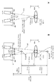
도 1은 본 발명의 제1 실시 형태에 관한 입체 영상 촬상 장치의 포커스 거리, 오프셋 거리 및 폭주 거리의 예를 도시하는 설명도이다.
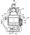
도 2는 본 발명의 제1 실시 형태에 관한 입체 영상 촬상 장치의 정면도이다.
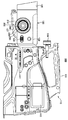
도 3은 본 발명의 제1 실시 형태에 관한 입체 영상 촬상 장치의 좌측면도이다.
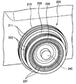
도 4는 본 발명의 제1 실시 형태에 관한 조정 링의 사시도이다.
도 5는 본 발명의 제1 실시 형태에 관한 조정 링의 측면도이다.
도 6은 본 발명의 제1 실시 형태에 관한 줌, 포커스 및 컨버전스의 조정 회로의 구성예를 도시하는 블록도이다.
도 7은 본 발명의 제1 실시 형태에 관한 오프셋 거리를 설정하기 위한 설정 메뉴의 표시예를 도시하는 설명도이다.
도 8은 본 발명의 제1 실시 형태에 관한 줌 조정시의 조작예를 도시하는 설명도이다.
도 9는 본 발명의 제1 실시 형태에 관한 포커스 조정시의 조작예를 도시하는 설명도이다.
도 10은 본 발명의 제1 실시 형태에 관한 컨버전스 조정시의 조작예를 도시하는 설명도이다.
도 11은 본 발명의 제2 실시 형태에 관한 자동 추종하는 오프셋 거리를 설정하기 위한 설정 메뉴의 표시예를 도시하는 설명도이다.BRIEF DESCRIPTION OF THE DRAWINGS It is explanatory drawing which shows the example of the focal length, the offset distance, and the runaway distance of the stereoscopic image pickup apparatus which concerns on 1st Embodiment of this invention.
2 is a front view of the stereoscopic image capturing apparatus according to the first embodiment of the present invention.
3 is a left side view of the stereoscopic image capturing apparatus according to the first embodiment of the present invention.
4 is a perspective view of the adjustment ring according to the first embodiment of the present invention.
5 is a side view of the adjustment ring according to the first embodiment of the present invention.
6 is a block diagram showing an example of a configuration of an adjustment circuit for zoom, focus, and convergence according to the first embodiment of the present invention.
7 is an explanatory diagram showing a display example of a setting menu for setting an offset distance according to the first embodiment of the present invention.
8 is an explanatory diagram showing an example of operation during zoom adjustment according to the first embodiment of the present invention.
It is explanatory drawing which shows the example of operation at the time of focus adjustment which concerns on 1st Embodiment of this invention.
It is explanatory drawing which shows the operation example at the time of convergence adjustment which concerns on 1st Embodiment of this invention.
It is explanatory drawing which shows the example of a display of the setting menu for setting the offset distance which automatically follows according to the 2nd Embodiment of this invention.
이하, 본 발명을 실시하기 위한 형태(이하, 실시 형태라고 함)에 대하여 설명한다. 또한, 설명은 이하의 순서로 행한다.EMBODIMENT OF THE INVENTION Hereinafter, the form (henceforth an embodiment) for implementing this invention is demonstrated. The description will be made in the following order.
1. 제1 실시 형태(폭주 거리를 자동 조정하는 예)1. First embodiment (example of automatically adjusting runaway distance)
2. 제2 실시 형태(폭주 거리를 자동 추종하는 예)2. Second embodiment (example of automatically following runaway distance)
3. 변형예3. Variations
<1. 제1 실시 형태><1. First Embodiment>
[폭주 거리를 자동 조정하는 예][Example of automatically adjusting runaway distance]
이하, 본 발명의 제1 실시 형태(이하, 「본 예」라고 함)에 대하여, 도 1 내지 도 10을 참조하여 설명한다.EMBODIMENT OF THE INVENTION Hereinafter, 1st Embodiment of this invention (henceforth "this example") is demonstrated with reference to FIGS.
본 실시 형태에서는 동일한 피사체를 복수의 시점에서 촬영하여 입체 영상을 생성하는 것이 가능한 2안 렌즈식 입체 영상 촬상 장치(100)에 적용한 예에 대하여 설명한다. 입체 영상 촬상 장치(100)는, 프로그램을 실행함으로써, 내부 블록이 연계하여 행하는 폭주 거리 조정 방법을 실현한다. 처음에, 포커스 거리, 오프셋 거리 및 폭주 거리의 관계에 대하여 도 1을 참조하여 설명한다.In this embodiment, an example in which the same subject is applied to the binocular lens-type stereoscopic
[포커스 거리, 오프셋 거리 및 폭주 거리의 설명][Description of Focus Distance, Offset Distance, and Runaway Distance]
도 1은 포커스 거리, 오프셋 거리 및 폭주 거리의 설명도이다. 도 1의 A는 피사체가 있는 위치에서 포커스점 및 폭주점이 일치하고 있는 예를 도시한다.1 is an explanatory diagram of a focus distance, an offset distance, and a runaway distance. 1A shows an example in which the focus point and the congestion point coincide at the position where the subject is located.
입체 영상 촬상 장치(100)는, 인간의 좌우 눈의 폭에 맞춘 기선 길이(IAD: Inter Axial Distance)만큼 이격하여 배치되는 좌우 한 쌍의 촬상 렌즈를 포함하는 좌측 렌즈 광학계(121L)와 우측 렌즈 광학계(121R)를 구비한다. 입체 영상 촬상 장치(100)에 실장되는 좌측 렌즈 광학계(121L)와 우측 렌즈 광학계(121R)는, 렌즈의 광축이 피사체를 향하여 교차하도록 비스듬하게 설치되고, 도시하지 않은 시프트 렌즈를 사용하여 각 광학계의 폭주점을 앞 또는 깊이 방향으로 이동시키고 있다.The stereoscopic
좌측 렌즈 광학계(121L)와 우측 렌즈 광학계(121R)는 주종 관계를 갖고 있으며, 주가 되는 광학계의 동작에 종이 되는 광학계의 동작이 연동된다. 본 예에서는 좌측 렌즈 광학계(121L)를 주로 하고, 우측 렌즈 광학계(121R)를 종으로 하고 있다. 그리고, 주가 되는 좌측 렌즈 광학계(121L)를 피사체를 향하여 포커스를 맞추고 있다. 또한, 우측 렌즈 광학계(121R)를 주로 하고, 좌측 렌즈 광학계(121L)를 종으로 하는 운용으로 하여도 된다.The left lens
입체 영상 촬상 장치(100)는 피사체의 정면에 위치하고 있으며, 좌측 렌즈 광학계(121L)와 우측 렌즈 광학계(121R)는, 일례로서 피사체인 인간의 헤드부에 포커스를 맞추고 있다. 이하의 설명에서는 좌측 렌즈 광학계(121L)의 광축 방향이며, 좌측 렌즈 광학계(121L)의 촬상 렌즈부터 포커스점 F1까지의 거리를 「포커스 거리」라고 칭한다. 마찬가지로, 좌측 렌즈 광학계(121L)의 광축 방향이며, 좌측 렌즈 광학계(121L)의 촬상 렌즈부터 폭주점 A1까지의 거리를 「폭주 거리」라고 칭한다.The stereoscopic
좌측 렌즈 광학계(121L)와 우측 렌즈 광학계(121R)는, 기선 길이의 중점에서의 수직선을 선 대칭의 축선으로 하여, 좌측 렌즈 광학계(121L)의 동작에 따라 우측 렌즈 광학계(121R)가 동작한다. 이로 인해, 우측 렌즈 광학계(121R)에서의 포커스 거리와 폭주 거리는, 좌측 렌즈 광학계(121L)에서의 각 거리와 동등하다.In the left lens
도 1의 B는 폭주점 B1, B2를 설정한 예를 도시한다.1B shows an example in which the congestion points B1 and B2 are set.
각 광학계는 피사체인 인간의 헤드부에 포커스점 F2를 정하여 포커스를 맞추고 있다. 여기서, 포커스점 F2를 기준으로 한 경우에 있어서의 폭주점 B1 또는 폭주점 B2까지의 거리를 「오프셋 거리」라고 칭한다. 예를 들어, 포커스점 F2를 오프셋 거리의 기준인 ±0m로 한 경우에, 포커스점 F2보다 촬영 렌즈로부터 보아 전방측을 마이너스의 오프셋 거리로 설정하고, 포커스점 F2보다 촬영 렌즈로부터 보아 안측을 플러스의 오프셋 거리로 설정한다. 이로 인해, 오프셋 거리가 -1m로 설정되면, 피사체의 1m 앞쪽에 폭주점 B2가 설정된다. 그리고, 포커스 거리에 오프셋 거리(-1m)를 더함으로써, 폭주점 B2에서의 폭주 거리(-1m)가 구해진다. 이때, 포커스 거리>폭주 거리의 관계를 만족한다.Each optical system focuses on a human head, which is a subject, by setting a focus point F2. Here, the distance to the runaway point B1 or the runaway point B2 in the case where the focus point F2 is used as a reference is referred to as an "offset distance". For example, in the case where the focus point F2 is set to ± 0 m as the reference for the offset distance, the front side is set to a negative offset distance when viewed from the photographing lens than the focus point F2, and the inner side is added as viewed from the photographing lens than the focus point F2. Set to the offset distance of. For this reason, when the offset distance is set to -1m, the congestion point B2 is set 1m in front of the subject. Then, by adding the offset distance (-1 m) to the focal length, the runaway distance (-1 m) at the runaway point B2 is obtained. At this time, the relationship between the focus distance> the runaway distance is satisfied.
한편, 오프셋 거리가 +1m로 설정되면, 피사체의 1m 안쪽에 폭주점 B1이 설정된다. 그리고, 포커스 거리에 오프셋 거리(+1m)를 더함으로써, 폭주점 B1에서의 폭주 거리(+1m)가 구해진다. 이때, 포커스 거리<폭주 거리의 관계를 만족한다.On the other hand, when the offset distance is set to + 1m, the congestion point B1 is set inside 1m of the subject. Then, by adding an offset distance (+1 m) to the focus distance, the runaway distance (+1 m) at the runaway point B1 is obtained. At this time, the relationship between the focus distance & the runaway distance is satisfied.
또한, 도 1의 B에서는 주가 되는 좌측 렌즈 광학계(121L)의 광축 상의 거리를 「오프셋 거리」로서 정의한 후에 설명하고 있지만, 좌측 렌즈 광학계(121L)와 우측 렌즈 광학계(121R)의 광축의 중심선(본 예에서는 수직선) 상으로 다시 정의하여도 된다. 그리고, 포커스를 맞춘 피사체가 화면의 안쪽에 있는 것을 강조하고자 하는 경우에는, 포커스 거리보다 짧은 거리에 폭주점을 설정하면 된다. 한편, 포커스를 맞춘 피사체를 화면으로부터 떠오르게 하고 싶은 경우에는, 포커스 거리보다 긴 거리에 폭주점을 설정하면 된다.In FIG. 1B, the distance on the optical axis of the left lens
[입체 영상 촬상 장치의 구성][Configuration of Stereoscopic Imaging Apparatus]
도 2는 본 발명의 제1 실시 형태에 관한 입체 영상 촬상 장치(100)의 정면도를 도시한다.2 is a front view of the stereoscopic
도 3은 본 발명의 제1 실시 형태에 관한 입체 영상 촬상 장치(100)의 좌측면도를 도시한다.3 is a left side view of the stereoscopic
입체 영상 촬상 장치(100)는 본체부(110)와 렌즈부(120)를 갖는다.The stereoscopic
2안 렌즈식 입체 영상 촬상 장치(100)는, 좌우의 렌즈를 통하여 각각 도입한 피사체의 좌우의 상을, 촬상 소자에서 전기적인 신호로 변환하여 A/D 변환을 행한다. 그 후, HDV(High-Definition Video) 방식 등의 소정의 방식으로 압축 부호화하여, 좌우 각각의 반도체 기록 매체에 기록한다. 촬상 소자에는, 예를 들어 CCD(Charge Coupled Device) 이미지나 CMOS(Complementary Metal Oxide Semiconductor) 센서 등이 사용된다.The binocular lens-type stereoscopic
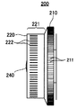
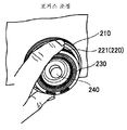
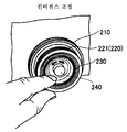
입체 영상 촬상 장치(100)의 측면에는 줌, 포커스 및 컨버전스의 조정을 행하기 위한 3개의 링으로 구성되는 조정 링(200)을 구비한다. 3개의 링은 서로 동축(同軸)이 되도록 조합되고, 또한 서로 독립하여 회동하여 조작하는 것이 가능하다. 그리고, 줌, 포커스 및 컨버전스의 조정을 행하기 위하여, 줌 링(210), 포커스 링(220) 및 컨버전스 링(230)이 설치되어 있다. 촬영자가 원하는 입체 영상을 촬상하기 위해서는, 일반적으로는 교대로 반복 포커스와 컨버전스를 조정하는 경우가 많다. 그러나, 조정 링(200)과 동축으로 각각 독립하여 회동 가능한 포커스 조정용 포커스 링(220)과 컨버전스 조정용 컨버전스 링(230)을 사용하기 때문에, 조정 작업의 효율을 향상시킬 수 있다.The side of the stereoscopic
본 예의 입체 영상 촬상 장치(100)는, 컨버전스 링(230)의 중심 부분에 배치되어, 포커스 링(220) 및 컨버전스 링(230)의 축 방향으로 돌출된 지시 버튼(240)을 구비한다. 지시 버튼(240)이 촬영자에 의해 눌러지면, 컨버전스 링(230)에 의한 폭주 거리의 조정과는 별도로, 제어 회로(312)(후술하는 도 6 참조)에 대하여 폭주 거리의 조정을 개시하는 지시를 행한다. 지시 버튼(240)은, 좌우 한 쌍의 촬상 렌즈의 광축이 교차하는 폭주점부터 촬상 렌즈까지의 폭주 거리의 조정을 개시하는 지시를 행하는 조정 지시부로서 사용된다.The stereoscopic
이밖에, 본체부(110)에는 외부 기기에 접속하기 위하여 사용되는 각종 인터페이스군, 각종 조작 버튼군, 핸들(111), 표시부(113), 도시하지 않은 배터리 어댑터, 메모리 카드 슬롯 등이 설치되어 있다. 인터페이스군 및 배터리 어댑터는 주로 본체부(110)의 후방부에 설치되어 있다. 인터페이스로서는, 예를 들어 디지털 영상 및 디지털 음성의 입출력, 아날로그 영상 및 아날로그 음성의 입출력, 제어용 입력, 모니터 출력, 헤드폰 출력 등이 있다. 또한, 배터리 어댑터에는, 도시하지 않은 배터리를 착탈하는 것이 가능하게 되어 있다.In addition, the
조작부(115), 표시부(113) 및 메모리 카드 슬롯은 주로 본체부(110)의 측면에 설치되어 있다. 조작부(115)에는, 예를 들어 전원 버튼, 녹화 버튼, 재생 버튼, 빨리 감기 버튼, 되돌리기 버튼, 셔터 버튼, 그 밖의 버튼이 포함된다. 표시부(113)는 촬상 중의 영상이나 기록 영상, 기능 선택이나 설정 조작을 행하기 위한 그래피컬 유저 인터페이스(GUI: Graphical User Interface) 등의 표시나, 오프셋 거리를 설정하는 설정부로서 사용되거나 한다. 그리고, 표시부(113)는, 본체부(110)의 측면에 있어서 2축의 주위 방향으로 회동 가능하게 설치되어 있다. 메모리 카드 슬롯은, 반도체 기록 매체인 메모리 카드의 착탈이 가능하게 되고, 이 메모리 카드에 대하여 디지털 영상 데이터의 기록 및 판독을 행하는 것이 가능하다.The
표시부(113)로서는, 예를 들어 액정 디스플레이나 유기 EL 디스플레이 등이 채용되고 있으며, 촬영자가 피사체를 촬상하면서 입체 영상을 확인하기 위하여 3D 모니터로서 사용할 수 있다. 그리고, 표시부(113)에는 오토 포커스 또는 매뉴얼에 의한 포커스의 설정을 구별하여 표시한다. 또한, 표시부(113)는, 주로 동작하는 좌측 렌즈 광학계(121L)에 의해 촬상된 좌측 영상만을 표시하거나, 좌측 영상을 녹색, 우측 영상을 적색으로 하는 애너글리프(anaglyph)로 표현하는 경우에, 녹색의 좌측 영상을 표시하거나 한다. 이들 영상은 도시하지 않은 뷰 파인더에 의해 표시하도록 하여도 된다.As the
조작 버튼군의 일부나 핸들(111)은, 주로 본체부(110)의 상면에 설치되어 있다. 핸들(111)은 촬영자가 입체 영상 촬상 장치(100)를 지지하기 위하여 사용된다. 핸들(111)의 전방부에는 마이크로폰(119)이 설치되고, 본체부(110)의 내부에는 CPU(Central Processing Unit) 등의 제어 회로, 좌우의 촬상 소자, 신호 처리 회로, 인코더 회로 등이 수납되어 있다.A part of the operation button group and the
렌즈부(120)에는, 우측 렌즈 광학계(121R)와 좌측 렌즈 광학계(121L)가 좌우 평행하게 설치되고, 설정된 폭주각에 따라 우측 렌즈 광학계(121R)와 좌측 렌즈 광학계(121L)의 광축이 기울어진다. 좌측 렌즈 광학계(121L)가 동작하면, 우측 렌즈 광학계(121R)는 줌, 포커스 및 컨버전스의 조정을 좌측 렌즈 광학계(121L)의 동작에 동기하여 행한다.In the
또한, 렌즈부(120)의 선단부에는, 우측 렌즈 광학계(121R)와 좌측 렌즈 광학계(121L)에 입사하는 광의 파장을 제한하는 렌즈 필터(123)가 설치되어 있다. 또한, 우측 렌즈 광학계(121R)와 좌측 렌즈 광학계(121L)의 촬상 렌즈를 여러가지 목적으로 보호하는 렌즈 후드(125)가 설치되어 있다.Further, a
렌즈부(120)의 측면에는, 조정 링(200) 외에 촬영자의 손에 의해 파지되는 그립부(127)가 설치되고, 그립부(127)에는 광각/망원 스위치(128)가 설치되어 있다. 또한, 렌즈부(120)의 측면에는, 우측 렌즈 광학계(121R) 및 좌측 렌즈 광학계(121L)에 들어가는 광의 양을 감소시키도록 조정하는 감광 필터 버튼(129)이 설치되어 있다. 또한, 노출을 조정함으로써 촬상하는 화상의 밝기를 조정하는 아이리스 다이얼(130) 등도 설치되어 있다.In addition to the
[조정 링의 구성][Configuration of Adjustment Ring]
이어서, 조정 링(200)의 구성에 대하여, 도 4와 도 5를 참조하여 설명한다.Next, the structure of the
도 4는 조정 링(200)의 사시도를 도시한다.4 shows a perspective view of the
도 5는 조정 링(200)의 측면도를 도시한다.5 shows a side view of the
조정 링(200)은, 줌을 조정하기 위한 줌 링(210), 포커스를 조정하기 위한 포커스 링(220), 및 컨버전스를 조정하기 위한 컨버전스 링(230)으로 구성된다. 줌 링(210), 포커스 링(220) 및 컨버전스 링(230)은 각각 내재적 중첩 구조로 조합되어, 서로 독립적으로 정ㆍ역방향으로 동축으로 회동 가능하게 구성되어 있다.The
줌 링(210)은 조정 링(200)에 있어서 가장 외주측에 위치하는 회동부이다.The
포커스 링(220)은, 회동됨으로써 광학계 포커스를 맞추어 포커스점을 조정하는 포커스 조정부로서 사용된다.The
컨버전스 링(230)은, 외경이 상이한 포커스 링(220)과 동축으로 내재적 중첩 구조로 조합되어, 포커스 링(220)과는 별도로 회동됨으로써 폭주점을 조정한다. 그리고, 컨버전스 링(230)은 줌 링(210)의 내측에서 회동 가능하며, 또한 포커스 링(220)의 내측에서 회동 가능하다. 따라서, 줌 링(210), 포커스 링(220), 컨버전스 링(230)의 외경은, 줌 링(210), 포커스 링(220), 컨버전스 링(230)의 순서대로 작아진다. 이로 인해, 촬영자는 조작하고 있는 링의 위치 관계를 용이하게 알 수 있어, 조작성의 향상이 기대된다.The
줌 링(210)의 외주면에는 미끄럼 방지용 슬릿(211)이 설치되어 있다. 또한, 포커스 링(220)은 줌 링(210)보다 축 방향에 있어서 돌출된 부분(221)을 갖는다. 이 돌출된 부분(221)의 외주면에 미끄럼 방지용 슬릿(222)이 설치되어 있다. 한편, 포커스 링(220)의 내측에 회동 가능하게 배치된 컨버전스 링(230)의 선단 위치는 포커스 링(220)의 선단 위치와 일치 혹은 대략 일치되어 있다. 컨버전스 링(230)의 선단 부분은 유발 형상으로 오목하게 되어 있으며, 이 오목한 부분의 내주면(법면)에 미끄럼 방지용 슬릿(231)이 설치되어 있다.An
상술한 바와 같이 조정 링(200)은, 줌 링(210)을 조정 링(200)에 있어서 가장 외주측에 배치하는 구성으로 되어 있다. 또한, 포커스 링(220)을 줌 링(210)의 내측에 배치하고, 컨버전스 링(230)을 포커스 링(220)의 내측에 배치하는 구성으로 되어 있다. 또한, 줌 링(210)으로부터 포커스 링(220)을 돌출시키고 있다.As described above, the
단, 이와 같은 구성에 한정되지 않고, 줌 링(210)을 조정 링(200)에 있어서 가장 내주측에 배치하고, 그 외주에 포커스 링(220), 컨버전스 링(230)의 순서대로 배치하여도 된다. 혹은, 컨버전스 링(230), 포커스 링(220)의 순서대로 배치하여도 된다. 또한, 조정 링(200)은 촬영자가 조작하기 쉬운 장소이면, 본체부(110)의 측면 이외의 장소에 설치하여도 된다. 또한, 포커스 링(220)으로부터 컨버전스 링(230)을 돌출시키고, 컨버전스 링(230)이 돌출된 부분의 외주면에 미끄럼 방지에 사용하는 슬릿을 설치하여도 된다.However, it is not limited to such a structure, Even if the
[줌, 포커스 및 컨버전스의 조정 회로][Adjustment circuit for zoom, focus and convergence]
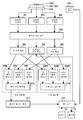
도 6은 줌, 포커스 및 컨버전스의 조정 회로의 구성예를 도시한다.6 shows an example of the configuration of an adjusting circuit of zoom, focus and convergence.
입체 영상 촬상 장치(100)는, 조정 링(200)의 줌 링(210), 포커스 링(220) 및 컨버전스 링(230)에 각각 대응하는 이하의 회로를 갖는다. 즉, 로터리 인코더(301, 302, 303), 광학계 제어 회로(304), 줌 구동 회로(305), 포커스 구동 회로(306), 컨버전스 구동 회로(307)이다. 또한, 좌측 광학계 줌 액추에이터(308L), 좌측 광학계 포커스 액추에이터(309L), 좌측 광학계 컨버전스 액추에이터(310L)가 있다. 마찬가지로, 우측 광학계 줌 액추에이터(308R), 우측 광학계 포커스 액추에이터(309R), 우측 광학계 컨버전스 액추에이터(310R)가 있다. 포커스 링(220)은, 우측 렌즈 광학계(121R)와 좌측 렌즈 광학계(121L)의 포커스점의 위치(포커스 거리)를 조정하는 포커스 조정부로서 사용된다.The stereoscopic
독립적으로 회동 조작되는 줌 링(210), 포커스 링(220) 및 컨버전스 링(230)에 의해 출력되는 각각의 회동 정보는, 각 링에 대응하여 설치된 로터리 인코더(301, 302, 303)에 의해 검출된다. 로터리 인코더(301, 302, 303)의 검출 정보는 CPU 등의 광학계 제어 회로(304)에 전송된다. 광학계 제어 회로(304)는 줌 조정에 대응하는 로터리 인코더(301)의 검출 정보에 기초하여, 줌 조정에 관한 소정의 연산 처리를 실행하여 제어량을 구하고, 제어량에 따른 제어 정보를 줌 구동 회로(305)에 공급한다.Each rotation information output by the
줌 구동 회로(305)는, 제어 정보에 기초하여 좌측 광학계 줌 액추에이터(308L)와 우측 광학계 줌 액추에이터(308R)를 구동한다. 이에 의해 우측 렌즈 광학계(121R)와 좌측 렌즈 광학계(121L)의 줌의 조정이 행해진다. 또한, 광학계 제어 회로(304)는 포커스 조정에 대응하는 로터리 인코더(302)의 검출 정보에 기초하여 포커스 조정에 관한 소정의 연산 처리를 실행하여 제어량을 구하고, 제어량에 따른 제어 정보를 포커스 구동 회로(306)에 공급한다.The
포커스 구동 회로(306)는, 제어 정보에 기초하여 좌측 광학계 포커스 액추에이터(309L) 및 우측 광학계 포커스 액추에이터(309R)를 구동한다. 이에 의해 우측 렌즈 광학계(121R)와 좌측 렌즈 광학계(121L)의 포커스의 조정이 행해진다.The
또한, 광학계 제어 회로(304)는, 컨버전스 조정에 대응하는 로터리 인코더(303)의 검출 정보에 기초하여 컨버전스 조정에 관한 소정의 연산 처리를 실행하여 제어량을 구한다. 그리고, 그 제어량에 따른 제어 정보를 컨버전스 구동 회로(307)에 공급한다. 컨버전스 구동 회로(307)는, 제어 정보에 기초하여 좌측 광학계 컨버전스 액추에이터(310L) 및 우측 광학계 컨버전스 액추에이터(310R)를 구동한다. 이에 의해 우측 렌즈 광학계(121R)와 좌측 렌즈 광학계(121L)의 컨버전스의 조정이 행해진다.In addition, the optical
또한, 입체 영상 촬상 장치(100)는, 좌측 렌즈 광학계(121L)로부터 수취하는 정보로부터, 기선 길이 및 포커스점에 기초하여, 촬상 렌즈부터 포커스점까지의 포커스 거리를 검출하는 포커스 거리 검출부로서의 포커스 포지션 센서(311)를 구비한다. 포커스 포지션 센서(311)는, 삼각 측량을 응용하여, 미리 판명되어 있는 기선 길이 및 포커스점으로부터 포커스 거리를 구할 수 있다.In addition, the stereoscopic
또한, 입체 영상 촬상 장치(100)는, 포커스 거리에 기초하여 폭주 거리를 구하는 제어 회로(312)를 구비한다. 제어 회로(312)는, 폭주 거리의 조정을 개시하는 지시를 행하는 지시 버튼(240)이 눌러지면, 촬상 렌즈부터 폭주점까지의 폭주 거리를 조정하는 제어부로서 사용된다. 이때, 제어 회로(312)는, 포커스 링(220)에 의해 포커스점이 조정된 후, 촬상 렌즈의 광축 방향에서의 포커스점부터 설정하고자 하는 폭주점까지의 거리를 오프셋 거리로 한다. 그리고, 촬상 렌즈부터 포커스점까지의 포커스 거리에 오프셋 거리를 더하여, 촬상 렌즈부터 폭주점까지의 폭주 거리를 조정한다.The stereoscopic
여기서, 도 1의 B를 참조하여 설명한 바와 같이, 제어 회로(312)는, 포커스점보다 안쪽에 폭주점이 위치하도록 조정하는 경우에는, 플러스의 오프셋 거리를 포커스 거리에 더한다. 한편, 포커스점보다 앞쪽에 폭주점이 위치하도록 조정하는 경우에는, 마이너스의 오프셋 거리를 포커스 거리에 더한다. 이에 의해, 촬영자가 지시 버튼(240)을 누르기만 하면 포커스 거리에 맞춘 폭주 거리의 조정을 자동적으로 행하는 것이 가능하게 된다.Here, as described with reference to FIG. 1B, the
이렇게 입체 영상 촬상 장치(100)는, 폭주 거리의 자동 조정을 실행하는 지시 버튼(240)과, 폭주점과 포커스점의 위치 관계를 설정하는 메뉴를 제시한다. 이 메뉴에는 표시부(113)에 표시되는 GUI가 포함되는 경우가 있지만, 본체부(110)에 설치한 조작 버튼 등에 의해 메뉴의 기능을 실현하여도 된다. 이 메뉴를 사용하면, 촬영자가 폭주점과 포커스점의 원하는 위치 관계(거리)를 오프셋 거리로 하여 사전에 설정해 둘 수 있다. 그리고, 촬영시에는 포커스를 맞춘 후, 지시 버튼(240)을 누르는 조작만으로 입체 영상 촬상 장치(100)가 자동적으로 폭주점 위치를 조정한다. 이로 인해, 촬영자가 수동으로 행하는 폭주점이나 포커스점의 조정 작업을 간략화하여, 용이하게 원하는 3D 영상을 얻는 것을 가능하게 한다.In this way, the stereoscopic
도 7은 표시부(113)에 표시되는 오프셋 거리를 설정하기 위한 설정 메뉴의 표시예를 도시한다.7 shows a display example of a setting menu for setting the offset distance displayed on the
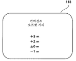
제어 회로(312)는, 조작부(115)의 입력 조작이 이루어지면, 촬영자가 오프셋 거리의 값을 설정하기 위하여 사용하는 메뉴 화면을 표시부(113)에 표시한다. 촬영자는, 조작부(115)의 조작 입력에 의해, 컨버전스 거리의 산출을 위하여 사용되는 오프셋 거리를 「컨버전스 오프셋 거리」로서 사전에 설정할 수 있다. 이로 인해, 입체 영상의 촬상시에는, 지시 버튼(240)이 눌러지면, 입체 영상 촬상 장치(100)는 설정된 오프셋 거리에 맞추어 폭주 거리를 조정할 수 있다.When the input operation of the
[선택 조작의 예][Example of Selection Operation]
여기서 선택 조작의 예를 설명한다.An example of the selection operation will be described here.
처음에, 촬영자는, 표시부(113)에 표시되고, 오프셋 거리를 설정하기 위한 메뉴 화면으로부터 오프셋 거리를 어느 값으로 할지 선택한다.First, the photographer is displayed on the
촬영시에는 피사체에 포커스를 맞춘 후, 제어 회로(312)는, 선택된 오프셋 거리에 기초하여, 포커스 포지션 센서(311)로부터 취득한 포커스 거리에 기초하여 폭주각을 구한다. 그리고, 제어 회로(312)는, 컨버전스 구동 회로(307)에 대하여 좌측 렌즈 광학계(121L)와 우측 렌즈 광학계(121R)에 포함되는 촬상 렌즈의 광축을 바꾸어 폭주점에 맞춘 폭주각을 설정한다.After focusing on the subject at the time of imaging, the
예를 들어, 폭주 거리는 다음과 같이 구해진다.For example, the runaway distance is obtained as follows.
표시부(113)의 메뉴 화면으로부터 조작부(115)를 통하여 설정된 오프셋 거리가 +1m, 포커스 거리가 3m인 경우, 폭주 거리는 4m=3m+1m로 한다. 이때, 좌측 렌즈 광학계(121L)와 우측 렌즈 광학계(121R)로부터 각각 반경 4m의 원호의 교점을 구한다. 이어서, 제어 회로(312)는, 좌측 렌즈 광학계(121L)와 우측 렌즈 광학계(121R)부터 원호의 교점까지의 광축의 각도(폭주각 θ)를 테이블(또는 계산)에 의해 구한다. 이 테이블에는, 미리 포커스 거리에 대한 폭주각의 관계가 기억되어 있다. 이로 인해, 제어 회로(312)는, 포커스 포지션 센서(311)에 의해 구해진 포커스 거리에 기초하여 테이블로부터 폭주각을 판독한다. 그리고, 제어 회로(312)는, 이 폭주각에 맞추어 폭주점이 이동하도록 컨버전스 구동 회로(307)에 컨버전스를 조정하는 지시를 행한다. 이에 의해, 렌즈군의 일부(예를 들어, 시프트 렌즈)는 촬영 렌즈의 광축의 직교면, 수평 방향 또는 좌우 방향으로 구동되고, 폭주각이 소정값 θ로 설정된다.When the offset distance set from the menu screen of the
그 후, 촬영자는 표시부(113)에 표시되는 영상을 보면서 입체 촬영의 효과를 확인한다. 여기서, 의도한 입체 촬영을 행할 수 없을 것 같으면, 오프셋 거리를 다시 재설정한다. 표시부(113)에는 입체 영상을 표시 가능한 3D 뷰 파인더 또는 3D 모니터가 사용되고 있기 때문에, 촬영자는 실시간으로 입체 촬영의 효과를 확인할 수 있다. 단, 입체 영상은, 촬영 후에 도시하지 않은 HDD 등으로부터 판독하여, 재생한 영상 데이터에 기초하여 확인할 수도 있다.After that, the photographer confirms the effect of stereoscopic imaging while watching the image displayed on the
이어서, 조정 링(200)의 조작예에 대하여, 도 8 내지 도 10을 참조하여 설명한다.Next, an operation example of the
도 8은 줌 조정시의 조작예를 도시한다.8 shows an example of operation during zoom adjustment.
촬영자는, 줌 조정시에 줌 링(210)의 외주면에 손가락을 대어 줌 링(210)을 회동 조작한다. 이 조작에 의해 로터리 인코더(301)에서 회동 정보가 검출되어 줌의 조정을 행할 수 있다.The photographer rotates the
도 9는 포커스 조정시의 조작예를 도시한다.9 shows an example of operation during focus adjustment.
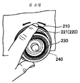
촬영자는, 포커스 조정시에 포커스 링(220)의 돌출된 부분(221)의 외주면에 손가락을 대어 포커스 링(220)을 회동 조작한다. 이 조작에 의해 로터리 인코더(302)에서 회동 정보가 검출되어 포커스의 조정을 행할 수 있다.The photographer rotates the
도 10은 컨버전스 조정시의 조작예를 도시한다.10 shows an example of operation during convergence adjustment.
촬영자는, 컨버전스 조정시에 컨버전스 링(230)의 선단 부분의 유발 형상으로 오목해진 부분의 내주면에 손가락을 대어 컨버전스 링(230)을 회동 조작한다. 이 조작에 의해 로터리 인코더(303)에서 회동 정보가 검출되어 컨버전스 조정을 행할 수 있다.When the photographer adjusts the convergence, the photographer rotates the
줌 링(210), 포커스 링(220) 및 컨버전스 링(230)은 모두 동축으로 조합한 조정 링(200)으로서 일체화되어 있다. 이로 인해, 촬영자는 약간 손을 이동시키는 것만으로 줌, 포커스, 컨버전스간에서 조정 대상을 원활하게 변경할 수 있다. 또한, 줌 링(210), 포커스 링(220) 및 컨버전스 링(230)은 모두 동축으로 회동되므로, 모두 마찬가지 감각으로 조작이 가능하다. 따라서, 조정 대상을 변경한 직후부터 빠르게 다른 조정을 개시할 수 있다. 특히, 포커스와 컨버전스의 조정과 같이 교대로, 또한 반복하여 행해지는 경우가 많은 조정 작업에 있어서 효율의 향상을 기대할 수 있다.The
이렇게 줌 링(210), 포커스 링(220) 및 컨버전스 링(230)을 모두 동축적으로 조합하여 조정 링(200)으로서 일체화되어 있다. 이에 의해, 촬영자는 약간 손을 이동시키는 것만으로 줌, 포커스, 컨버전스간에서 조정 대상을 원활하게 변경할 수 있다. 또한, 줌 링(210), 포커스 링(220) 및 컨버전스 링(230)은 모두 동축으로 회동되며, 접촉하지 않을 때에는 설정값이 변하지 않는다. 이로 인해, 촬영자가 조정 후에 손을 떼고 다시 조정을 행할 때에는, 이전 설정한 값으로부터 조정을 재개할 수 있다. 특히, 포커스와 컨버전스의 조정과 같이 교대로, 또한 반복하여 행해지는 경우가 많은 조정 작업에 있어서 효율의 향상을 기대할 수 있다. 또한, 줌 조정에 의해 포커스 조정이 필요하게 되는 경우에는, 줌 조정을 포함시켜 조정 작업의 효율화를 도모할 수 있다.In this way, the
이상 설명한 본 실시 형태에 관한 입체 영상 촬상 장치(100)에 따르면, 지시 버튼(240)을 누르기만 하면 오프셋 거리에 맞춘 폭주 거리를 용이하게 설정할 수 있다. 이로 인해, 종래와 같이 수동 조작으로 포커스 거리와 폭주 거리를 따로따로 설정하는 경우에 비하여, 폭주 거리의 변경이 완료될 때까지의 시간을 대폭 단축할 수 있다. 또한, 일단 설정한 오프셋 거리는 변하지 않기 때문에, 지시 버튼(240)을 누르기만 하면 오프셋 거리가 일정한 입체 영상을 안정되게 촬상할 수 있고, 촬영 도중에 오프셋 거리가 바뀌는 것에 의한 입체 영상의 위화감이 발생하지 않는다. 이로 인해, 고품질의 입체 영상을 촬영하는 경우에 있어서의 입체 영상 촬상 장치(100)의 조작성을 용이하게 할 수 있다.According to the stereoscopic
또한, 지시 버튼(240)은, 조정 링(200)의 중심부에 축 방향으로 돌출된 상태로 배치되어 있다. 이로 인해, 평소의 조작으로는 촬영자가 지시 버튼(240)에 잘못하여 접촉할 가능성이 없어, 의도하지 않은 입체 영상을 촬영하는 일이 없다.In addition, the instruction |
또한, 오프셋 거리는 사전에 유저에 의해 임의의 값을 설정하는 것이 가능하다. 이로 인해, 오프셋 거리의 변경이 용이하여, 폭주 거리가 조금씩 상이한 동일한 피사체를 촬영할 때 조작의 수고를 줄일 수 있다.The offset distance can be set by the user in advance. As a result, the offset distance can be easily changed, and the trouble of operation can be reduced when photographing the same subject having a slightly different runaway distance.
<2. 제2 실시 형태><2. Second Embodiment>
[폭주 거리를 자동 추종하는 예][Example of automatically following runaway distance]
이어서, 본 발명의 제2 실시 형태에 대하여, 도 11을 참조하여 설명한다. 본 실시 형태에서는 입체 영상을 촬상 중에 오토 포커스 등에 의해 포커스 거리가 바뀌는 경우라도, 이 포커스 거리의 변화에 폭주 거리를 자동적으로 추종하여 바꾸도록 한 입체 영상 촬상 장치(100)에 적용한 예에 대하여 설명한다. 이하의 설명에 있어서, 이미 제1 실시 형태에서 설명한 도 1 내지 도 4에 대응하는 부분에는 동일 부호를 붙이고, 상세한 설명을 생략한다.Next, 2nd Embodiment of this invention is described with reference to FIG. In this embodiment, even when the focus distance is changed by auto focus or the like during imaging of the stereoscopic image, an example applied to the stereoscopic
도 11은 자동 추종하는 오프셋 거리를 설정하기 위한 설정 메뉴의 표시예를 도시한다.Fig. 11 shows a display example of a setting menu for setting an offset distance for automatic tracking.
제어 회로(312)는, 포커스 링(220)에 의해 조정되는 포커스점에 대하여, 자동적으로 폭주점을 추종시켜 폭주 거리를 조정할지 여부를 선택시키는 메뉴 화면을 표시부(113)에 표시한다. 촬영자가 자동 추종을 온으로 설정하면, 설정한 시점 이후에 있어서, 포커스점이 동적으로 변동하여도 포커스 포지션 센서(311)가 자동적으로 포커스 거리를 구한다. 그리고, 제어 회로(312)는, 사전에 설정한 오프셋 거리를 유지하도록 포커스 거리에 기초하여 폭주점을 자동적으로 추종시켜 폭주 거리를 조정한다.The
이상 설명한 제2 실시 형태에 관한 입체 영상 촬상 장치(100)에 따르면, 폭주점의 자동 추종을 온함으로써, 촬영자는 오토 포커스 등을 사용하여 동적으로 포커스점을 바꾸는 경우라도 폭주점이 자동적으로 변화하여 폭주 거리가 조정된다. 이로 인해, 움직임이 있는 피사체나, 깊이 방향으로 이동하는 피사체 등을 촬영하는 경우에, 포커스를 맞추는 것만으로 의도한 폭주 거리에 의한 입체 영상의 촬영이 용이하게 된다. 이와 같이, 촬영자는 폭주점을 설정하기 위한 복잡한 조작이 불필요하며, 촬영에 집중할 수 있기 때문에, 촬영한 입체 영상의 품질을 높일 수 있다.According to the stereoscopic
<3. 변형예><3. Modifications>
또한, 이 폭주점의 자동 추종에 대하여 특히 메뉴 화면을 형성하지 않고, 처음부터 자동 추종을 온으로 설정해 두어도 된다. 이에 의해, 촬영자가 매뉴얼 또는 오토 포커스에 의해 포커스점을 움직여도 폭주점의 설정을 의식하지 않고 양호한 입체 영상을 촬상할 수 있다.In addition, the automatic tracking of this runaway point may be set to ON automatically from the beginning without forming a menu screen. Thus, even if the photographer moves the focus point by manual or auto focus, it is possible to capture a good stereoscopic image without being aware of the setting of the congestion point.
또한, 상술한 제1 및 제2 실시 형태에서는, 포커스 조정부로서 포커스 링(220)을 사용하고, 컨버전스 조정부로서 컨버전스 링(230)을 사용하고, 조정 지시부로서 지시 버튼(240)을 사용하였다. 그러나, 포커스 조정부, 컨버전스 조정부 및 조정 지시부로서는 링에 한정되지 않고, 슬라이드 스위치나 각종 스위치 기구를 사용하여도 된다. 또한, 표시부(113)에 GUI 표시시킨 메뉴에 의해 각종 값을 조정하도록 하여도 된다.In the first and second embodiments described above, the
또한, 상술한 제1 및 제2 실시 형태에서는 2안 렌즈식 입체 영상 촬상 장치(100)에 적용한 예를 설명하였지만, 종래와 같이 2대의 카메라를 사용하여 입체 영상을 생성하는 촬상 시스템에 사용하는 것도 가능하다.In addition, although the above-mentioned 1st and 2nd embodiment demonstrated the example applied to the binocular lens type stereoscopic
또한, 상술한 실시 형태예에서의 일련의 처리는 하드웨어에 의해 실행할 수 있지만, 소프트웨어에 의해 실행시킬 수도 있다. 일련의 처리를 소프트웨어에 의해 실행시키는 경우에는, 그 소프트웨어를 구성하는 프로그램이 전용 하드웨어에 내장되어 있는 컴퓨터, 또는 각종 기능을 실행하기 위한 프로그램을 인스톨한 컴퓨터에 의해 실행 가능하다. 예를 들어 범용의 퍼스널 컴퓨터 등에 원하는 소프트웨어를 구성하는 프로그램을 인스톨하여 실행시키면 된다.In addition, although the series of processes in the above-described embodiment can be executed by hardware, it can also be executed by software. When a series of processes are performed by software, it can be executed by the computer which the program which comprises the software is built in the dedicated hardware, or the computer which installed the program for performing various functions. For example, it is sufficient to install and execute a program constituting desired software in a general-purpose personal computer or the like.
또한, 상술한 실시 형태의 기능을 실현하는 소프트웨어의 프로그램 코드를 기록한 기록 매체를 시스템 혹은 장치에 공급하여도 된다. 또한, 그 시스템 혹은 장치의 컴퓨터(또는 CPU 등의 제어 장치)가 기록 매체에 저장된 프로그램 코드를 판독하여 실행함으로써도 기능이 실현되는 것은 물론이다.In addition, a recording medium on which program code of software for realizing the functions of the above-described embodiments may be supplied to the system or apparatus. Moreover, of course, the function is also realized by the computer (or control device such as a CPU) of the system or apparatus reading and executing the program code stored in the recording medium.
이 경우의 프로그램 코드를 공급하기 위한 기록 매체로서는, 예를 들어 플렉시블 디스크, 하드 디스크, 광 디스크, 광 자기 디스크, CD-ROM, CD-R, 자기 테이프, 불휘발성 메모리 카드, ROM 등을 사용할 수 있다.As a recording medium for supplying the program code in this case, for example, a flexible disk, a hard disk, an optical disk, a magneto-optical disk, a CD-ROM, a CD-R, a magnetic tape, a nonvolatile memory card, a ROM, or the like can be used. have.
또한, 컴퓨터가 판독한 프로그램 코드를 실행함으로써, 상술한 실시 형태의 기능이 실현된다. 더불어, 그 프로그램 코드의 지시에 기초하여, 컴퓨터 상에서 가동하고 있는 OS 등이 실제 처리의 일부 또는 전부를 행한다. 그 처리에 의해 상술한 실시 형태의 기능이 실현되는 경우도 포함된다.In addition, by executing the program code read by the computer, the functions of the above-described embodiments are realized. In addition, based on the instruction of the program code, an OS or the like running on the computer performs part or all of the actual processing. It also includes the case where the function of the above-described embodiment is realized by the processing.
또한, 본 발명은 상술한 실시 형태에 한정되는 것이 아니며, 특허청구범위에 기재된 본 발명의 요지를 일탈하지 않는 한, 그 밖의 여러가지 응용예, 변형예를 취할 수 있는 것은 물론이다.In addition, this invention is not limited to embodiment mentioned above, Of course, unless it deviates from the summary of this invention described in the claim, other various application examples and a modification can be taken.
또한, 본 발명은 이하와 같은 구성도 취할 수 있다.Moreover, this invention can also take the following structures.
(1) 소정의 기선 길이만큼 이격하여 배치되는 좌우 한 쌍의 촬상 렌즈를 포함하는 광학계와,(1) an optical system including a pair of left and right imaging lenses arranged to be spaced apart by a predetermined base line length,
상기 광학계의 포커스를 맞추어 포커스점을 조정하는 포커스 조정부와,A focus adjuster for adjusting a focus point by focusing the optical system;
상기 포커스 조정부에 의해 포커스점이 조정된 후, 상기 촬상 렌즈의 광축 방향에서의 상기 포커스점부터 설정하고자 하는 폭주점까지의 거리를 오프셋 거리로 하여, 상기 촬상 렌즈부터 상기 포커스점까지의 포커스 거리에 상기 오프셋 거리를 더하여, 상기 촬상 렌즈부터 상기 폭주점까지의 폭주 거리를 조정하는 제어부를 구비하는, 입체 영상 촬상 장치.After the focus point is adjusted by the focus adjustment unit, the distance from the focus point in the optical axis direction of the imaging lens to the constrained point to be set is an offset distance, and the focus distance from the imaging lens to the focus point is And a control unit for adjusting the runaway distance from the imaging lens to the runaway point by adding an offset distance.
(2) 상기 제어부는, 상기 포커스점보다 안쪽에 상기 폭주점이 위치하도록 조정하는 경우에는, 플러스의 상기 오프셋 거리를 상기 포커스 거리에 더하고, 상기 포커스점보다 앞쪽에 상기 폭주점이 위치하도록 조정하는 경우에는, 마이너스의 상기 오프셋 거리를 상기 포커스 거리에 더하는, 상기 (1)에 기재된 입체 영상 촬상 장치.(2) In the case where the control point adjusts the congestion point to be located inward from the focus point, the control unit adds the positive offset distance to the focus distance and adjusts the congestion point to be in front of the focus point. And the negative offset distance is added to the focal length. The stereoscopic image imaging apparatus according to (1).
(3) 또한, 상기 오프셋 거리를 설정하는 설정부와,(3) a setting unit for setting the offset distance;
상기 폭주 거리의 조정을 개시하는 지시를 행하는 조정 지시부와,An adjustment instructing section for instructing to start adjustment of the runaway distance;
상기 기선 길이 및 상기 포커스점에 기초하여, 상기 촬상 렌즈부터 상기 포커스점까지의 포커스 거리를 검출하는 포커스 거리 검출부를 구비하는, 상기 (1) 또는 (2)에 기재된 입체 영상 촬상 장치.The stereoscopic image capturing apparatus according to (1) or (2), further comprising a focus distance detector that detects a focus distance from the imaging lens to the focus point based on the base line length and the focus point.
(4) 상기 포커스 조정부는 회동됨으로써 상기 광학계의 포커스를 조정하는 포커스 링이며,(4) the focus adjusting section is a focus ring for adjusting the focus of the optical system by being rotated,
외경이 상이한 상기 포커스 링과 동축으로 내재적 중첩 구조로 조합되어, 상기 포커스 링과는 별도로 회동됨으로써, 상기 폭주 거리의 조정을 행하는 컨버전스 링을 구비하고,And a convergence ring for adjusting the runaway distance by combining an intrinsic overlapping structure coaxially with the focus ring having different outer diameters and rotating separately from the focus ring,
상기 조정 지시부는, 상기 포커스 링 및 상기 컨버전스 링의 축 방향으로 돌출되어 눌러짐으로써, 상기 컨버전스 링에 의한 상기 폭주 거리의 조정과는 별도로, 상기 제어부에 대하여 상기 폭주 거리의 조정을 개시하는 지시를 행하는 버튼인, 상기 (1) 내지 (3) 중 어느 하나에 기재된 입체 영상 촬상 장치.The adjustment instructing section protrudes in the axial direction of the focus ring and the convergence ring and is pressed to instruct the control unit to start the adjustment of the runaway distance separately from the adjustment of the runaway distance by the convergence ring. The stereoscopic image imaging device according to any one of (1) to (3), which is a button to be executed.
(5) 상기 제어부는, 상기 오프셋 거리의 값을 설정하는 메뉴 화면을 표시부에 표시하는, 상기 (1) 내지 (4) 중 어느 하나에 기재된 입체 영상 촬상 장치.(5) The stereoscopic image imager according to any one of (1) to (4), wherein the control unit displays a menu screen on which a value of the offset distance is set on a display unit.
(6) 상기 제어부는, 상기 포커스 조정부에 의해 조정되는 포커스에 추종하여, 상기 제어부가 상기 폭주 거리를 조정할지 여부를 선택시키는 메뉴 화면을 표시부에 표시하는, 상기 (1) 내지 (4) 중 어느 하나에 기재된 입체 영상 촬상 장치.(6) The said control part follows a focus adjusted by the said focus adjustment part, and displays the menu screen which selects whether the said control part adjusts the runaway distance to a display part, Any of said (1)-(4) The stereoscopic image pickup apparatus according to one of the above.
(7) 소정의 기선 길이만큼 이격하여 배치되는 좌우 한 쌍의 촬상 렌즈를 포함하는 광학계의 포커스를 맞추어 포커스점을 조정하는 것과,(7) adjusting the focus point by focusing an optical system including a pair of left and right imaging lenses arranged to be spaced apart by a predetermined base line length;
상기 촬상 렌즈의 광축 방향에서의 상기 포커스점부터 설정하고자 하는 폭주점까지의 거리를 오프셋 거리로 하여, 상기 촬상 렌즈부터 상기 포커스점까지의 포커스 거리에 상기 오프셋 거리를 더하여, 상기 촬상 렌즈부터 상기 폭주점까지의 폭주 거리를 조정하는 것을 포함하는, 폭주 거리 조정 방법.By setting the distance from the focus point in the optical axis direction of the imaging lens to the runaway point to be set as the offset distance, the offset distance is added to the focus distance from the imaging lens to the focus point, and the runaway from the imaging lens A runaway distance adjustment method comprising adjusting the runaway distance to a point.
(8) 소정의 기선 길이만큼 이격하여 배치되는 좌우 한 쌍의 촬상 렌즈를 포함하는 광학계의 포커스를 맞추어 포커스점을 조정하는 수순과,(8) a procedure for adjusting a focus point by focusing an optical system including a pair of left and right imaging lenses arranged to be spaced apart by a predetermined base line length;
상기 촬상 렌즈의 광축 방향에서의 상기 포커스점부터 설정하고자 하는 폭주점까지의 거리를 오프셋 거리로 하여, 상기 촬상 렌즈부터 상기 포커스점까지의 포커스 거리에 상기 오프셋 거리를 더하여, 상기 촬상 렌즈부터 상기 폭주점까지의 폭주 거리를 조정하는 수순을 컴퓨터에 실행시키는, 프로그램.By setting the distance from the focus point in the optical axis direction of the imaging lens to the runaway point to be set as the offset distance, the offset distance is added to the focus distance from the imaging lens to the focus point, and the runaway from the imaging lens A program that causes a computer to execute a procedure for adjusting the runaway distance to a point.
100: 입체 영상 촬상 장치
110: 본체부
113: 표시부
115: 조작부
120: 렌즈부
121L: 좌측 렌즈 광학계
121R: 우측 렌즈 광학계
123: 렌즈 필터
125: 렌즈 후드
200: 조정 링
210: 줌 링
220: 포커스 링
230: 컨버전스 링
240: 설정 버튼
311: 포커스 포지션 센서
312: 제어 회로100: stereoscopic image pickup device
110:
113: display unit
115: control panel
120: lens unit
121L: Left lens optical system
121R: Right lens optical system
123: lens filter
125: lens hood
200: adjustable ring
210: zoom ring
220: focus ring
230: convergence ring
240: setting button
311: focus position sensor
312: control circuit
Claims (8)
소정의 기선(基線) 길이만큼 이격하여 배치되는 좌우 한 쌍의 촬상 렌즈를 포함하는 광학계와,
상기 광학계의 포커스를 맞추어 포커스점을 조정하는 포커스 조정부와,
상기 포커스 조정부에 의해 포커스점이 조정된 후, 상기 촬상 렌즈의 광축 방향에서의 상기 포커스점부터 설정하고자 하는 폭주점(輻輳点)까지의 거리를 오프셋 거리로 하여, 상기 촬상 렌즈부터 상기 포커스점까지의 포커스 거리에 상기 오프셋 거리를 더하여, 상기 촬상 렌즈부터 상기 폭주점까지의 폭주 거리를 조정하는 제어부를 구비하는, 입체 영상 촬상 장치.As a stereoscopic image pickup device,
An optical system including a pair of left and right imaging lenses arranged to be spaced apart by a predetermined base line length,
A focus adjuster for adjusting a focus point by focusing the optical system;
After the focus point is adjusted by the focus adjustment unit, the distance from the focus point in the optical axis direction of the imaging lens to the constrained point to be set is an offset distance, from the imaging lens to the focus point. And a control unit for adjusting the runaway distance from the imaging lens to the runaway point by adding the offset distance to a focal length.
상기 오프셋 거리를 설정하는 설정부와,
상기 폭주 거리의 조정을 개시하는 지시를 행하는 조정 지시부와,
상기 기선 길이 및 상기 포커스점에 기초하여, 상기 촬상 렌즈부터 상기 포커스점까지의 포커스 거리를 검출하는 포커스 거리 검출부를 더 구비하는, 입체 영상 촬상 장치.3. The method of claim 2,
A setting unit for setting the offset distance;
An adjustment instructing section for instructing to start adjustment of the runaway distance;
And a focus distance detector for detecting a focus distance from the imaging lens to the focus point based on the base line length and the focus point.
상기 포커스 조정부는, 회동(回動)됨으로써 상기 광학계의 포커스를 조정하는 포커스 링이며,
외경이 상이한 상기 포커스 링과 동축으로 내재적 중첩 구조로 조합되어, 상기 포커스 링과는 별도로 회동됨으로써, 상기 폭주 거리의 조정을 행하는 컨버전스 링을 구비하고,
상기 조정 지시부는, 상기 포커스 링 및 상기 컨버전스 링의 축 방향으로 돌출되어 눌러짐으로써, 상기 컨버전스 링에 의한 상기 폭주 거리의 조정과는 별도로, 상기 제어부에 대하여 상기 폭주 거리의 조정을 개시하는 지시를 행하는 버튼인, 입체 영상 촬상 장치.The method of claim 3,
The focus adjusting unit is a focus ring for adjusting the focus of the optical system by rotating.
And a convergence ring for adjusting the runaway distance by combining an intrinsic overlapping structure coaxially with the focus ring having different outer diameters and rotating separately from the focus ring,
The adjustment instructing section protrudes in the axial direction of the focus ring and the convergence ring and is pressed to instruct the control unit to start the adjustment of the runaway distance separately from the adjustment of the runaway distance by the convergence ring. A stereoscopic image pickup device, which is a button to be performed.
소정의 기선 길이만큼 이격하여 배치되는 좌우 한 쌍의 촬상 렌즈를 포함하는 광학계의 포커스를 맞추어 포커스점을 조정하는 단계와,
상기 촬상 렌즈의 광축 방향에서의 상기 포커스점부터 설정하고자 하는 폭주점까지의 거리를 오프셋 거리로 하여, 상기 촬상 렌즈부터 상기 포커스점까지의 포커스 거리에 상기 오프셋 거리를 더하여, 상기 촬상 렌즈부터 상기 폭주점까지의 폭주 거리를 조정하는 단계를 포함하는, 폭주 거리 조정 방법.As a runaway distance adjustment method,
Adjusting a focus point by focusing an optical system including a pair of left and right imaging lenses arranged to be spaced apart by a predetermined base line length;
By setting the distance from the focus point in the optical axis direction of the imaging lens to the runaway point to be set as the offset distance, the offset distance is added to the focus distance from the imaging lens to the focus point, and the runaway from the imaging lens Adjusting the runaway distance to a point.
상기 촬상 렌즈의 광축 방향에서의 상기 포커스점부터 설정하고자 하는 폭주점까지의 거리를 오프셋 거리로 하여, 상기 촬상 렌즈부터 상기 포커스점까지의 포커스 거리에 상기 오프셋 거리를 더하여, 상기 촬상 렌즈부터 상기 폭주점까지의 폭주 거리를 조정하는 수순을 컴퓨터에 실행시키는, 프로그램.A procedure of adjusting a focus point by focusing an optical system including a pair of left and right imaging lenses arranged to be spaced apart by a predetermined base line length,
By setting the distance from the focus point in the optical axis direction of the imaging lens to the runaway point to be set as the offset distance, the offset distance is added to the focus distance from the imaging lens to the focus point, and the runaway from the imaging lens A program that causes a computer to execute a procedure for adjusting the runaway distance to a point.
Applications Claiming Priority (3)
| Application Number | Priority Date | Filing Date | Title |
|---|---|---|---|
| JP2011085564A JP2012220679A (en) | 2011-04-07 | 2011-04-07 | Stereoscopic video imaging apparatus, convergence distance adjustment method, and program |
| JPJP-P-2011-085564 | 2011-04-07 | ||
| PCT/JP2012/001815 WO2012137423A1 (en) | 2011-04-07 | 2012-03-15 | Stereoscopic video imaging apparatus, convergence distance adjustment method, and program for convergence distance adjustment method |
Publications (1)
| Publication Number | Publication Date |
|---|---|
| KR20140020901A true KR20140020901A (en) | 2014-02-19 |
Family
ID=46968839
Family Applications (1)
| Application Number | Title | Priority Date | Filing Date |
|---|---|---|---|
| KR1020137023911A KR20140020901A (en) | 2011-04-07 | 2012-03-15 | Stereoscopic video imaging apparatus, convergence distance adjustment method, and program for convergence distance adjustment method |
Country Status (7)
| Country | Link |
|---|---|
| US (1) | US20140240465A1 (en) |
| JP (1) | JP2012220679A (en) |
| KR (1) | KR20140020901A (en) |
| CN (1) | CN103477280A (en) |
| BR (1) | BR112013025253A2 (en) |
| TW (1) | TWI457691B (en) |
| WO (1) | WO2012137423A1 (en) |
Families Citing this family (6)
| Publication number | Priority date | Publication date | Assignee | Title |
|---|---|---|---|---|
| JPWO2012023168A1 (en) * | 2010-08-19 | 2013-10-28 | パナソニック株式会社 | Stereoscopic imaging device and stereoscopic imaging method |
| JP2014153471A (en) * | 2013-02-06 | 2014-08-25 | Canon Inc | Stereoscopic photography system |
| US9544574B2 (en) * | 2013-12-06 | 2017-01-10 | Google Inc. | Selecting camera pairs for stereoscopic imaging |
| TWI561908B (en) * | 2015-03-27 | 2016-12-11 | Vivotek Inc | Auto focus method and apparatus using the same method |
| WO2017218834A1 (en) | 2016-06-17 | 2017-12-21 | Kerstein Dustin | System and method for capturing and viewing panoramic images having motion parralax depth perception without images stitching |
| JP7023699B2 (en) * | 2017-12-14 | 2022-02-22 | キヤノン株式会社 | Optical equipment |
Family Cites Families (17)
| Publication number | Priority date | Publication date | Assignee | Title |
|---|---|---|---|---|
| JPH0666967B2 (en) * | 1986-12-26 | 1994-08-24 | 日本放送協会 | Convergence angle controller for stereoscopic camera |
| JPH07264633A (en) * | 1994-03-24 | 1995-10-13 | Sanyo Electric Co Ltd | Stereoscopic video camera |
| JPH08201940A (en) * | 1995-01-30 | 1996-08-09 | Olympus Optical Co Ltd | Stereoscopic image pickup device |
| JP4235291B2 (en) * | 1998-10-02 | 2009-03-11 | キヤノン株式会社 | 3D image system |
| JP2001016617A (en) * | 1999-06-30 | 2001-01-19 | Canon Inc | Image pickup device, its convergence control method, storage medium and optical device |
| JP2001202843A (en) * | 2000-01-17 | 2001-07-27 | Matsushita Electric Ind Co Ltd | Switch device, video camera and method of operating the same |
| JP2002090921A (en) * | 2000-09-11 | 2002-03-27 | Canon Inc | Stereoscopic photographic optical unit and stereoscopic photographic optical system |
| JP2002112288A (en) * | 2000-09-29 | 2002-04-12 | Canon Inc | Stereoscopic photographing optical unit and stereoscopic image photographing system |
| JP2002247603A (en) * | 2001-02-16 | 2002-08-30 | Canon Inc | Stereoscopic photographing optical device and stereoscopic photographing system |
| JP2004208211A (en) * | 2002-12-26 | 2004-07-22 | Canon Inc | Stereoscopic video imaging apparatus |
| WO2005073773A1 (en) * | 2004-01-30 | 2005-08-11 | Matsushita Electric Industrial Co., Ltd. | Lens barrel and imaging device provided with lens barrel, and assembling method for lens barrel |
| JP2006301340A (en) * | 2005-04-21 | 2006-11-02 | Canon Inc | Zoom lens |
| JP2008059796A (en) * | 2006-08-29 | 2008-03-13 | Auto Network Gijutsu Kenkyusho:Kk | Operating system and operating apparatus |
| JP2009017128A (en) * | 2007-07-03 | 2009-01-22 | Sony Corp | Camera support device |
| US7899321B2 (en) * | 2009-03-23 | 2011-03-01 | James Cameron | Stereo camera with automatic control of interocular distance |
| US8238741B2 (en) * | 2009-03-24 | 2012-08-07 | James Cameron & Vincent Pace | Stereo camera platform and stereo camera |
| US8265477B2 (en) * | 2010-03-31 | 2012-09-11 | James Cameron | Stereo camera with preset modes |
-
2011
- 2011-04-07 JP JP2011085564A patent/JP2012220679A/en active Pending
-
2012
- 2012-03-15 KR KR1020137023911A patent/KR20140020901A/en not_active Application Discontinuation
- 2012-03-15 US US14/008,650 patent/US20140240465A1/en not_active Abandoned
- 2012-03-15 WO PCT/JP2012/001815 patent/WO2012137423A1/en active Application Filing
- 2012-03-15 CN CN2012800163243A patent/CN103477280A/en active Pending
- 2012-03-15 BR BR112013025253A patent/BR112013025253A2/en not_active IP Right Cessation
- 2012-03-28 TW TW101110841A patent/TWI457691B/en not_active IP Right Cessation
Also Published As
| Publication number | Publication date |
|---|---|
| JP2012220679A (en) | 2012-11-12 |
| TW201250372A (en) | 2012-12-16 |
| CN103477280A (en) | 2013-12-25 |
| BR112013025253A2 (en) | 2017-02-07 |
| WO2012137423A1 (en) | 2012-10-11 |
| US20140240465A1 (en) | 2014-08-28 |
| TWI457691B (en) | 2014-10-21 |
Similar Documents
| Publication | Publication Date | Title |
|---|---|---|
| JP5595499B2 (en) | Monocular stereoscopic imaging device | |
| JP5474234B2 (en) | Monocular stereoscopic imaging apparatus and control method thereof | |
| JP4897940B2 (en) | Stereo imaging device | |
| JP5788518B2 (en) | Monocular stereoscopic photographing apparatus, photographing method and program | |
| JP2011211552A (en) | Imaging device and method, and program | |
| JP2010081010A (en) | Three-dimensional imaging device, method and program | |
| JP4764854B2 (en) | Imaging apparatus, image reproducing apparatus, imaging method, system, and program | |
| JP5705883B2 (en) | Lens device | |
| JP4533735B2 (en) | Stereo imaging device | |
| JP2011259168A (en) | Stereoscopic panoramic image capturing device | |
| KR20140020901A (en) | Stereoscopic video imaging apparatus, convergence distance adjustment method, and program for convergence distance adjustment method | |
| JP5611469B2 (en) | Stereoscopic imaging apparatus and method | |
| JP2008242185A (en) | Digital camera and autofocus device | |
| JP4711073B2 (en) | Auto focus system | |
| JP2021005063A (en) | Imaging apparatus | |
| JP5580486B2 (en) | Image output apparatus, method and program | |
| JP2012053303A (en) | Stereoscopic camera device and electronic information device | |
| JP2005070077A (en) | Digital camera | |
| JP2011030123A (en) | Imaging apparatus, control method of the same, and computer program | |
| JP2012080515A (en) | 3-d image pickup apparatus | |
| JP7330926B2 (en) | Filming system and remote control system | |
| JP2012227578A (en) | Camera | |
| JP2006145872A (en) | Auto focus area display device | |
| JP2011077680A (en) | Stereoscopic camera and method for controlling photographing | |
| JP2011082999A (en) | Three-dimensional photographing device and method, and program |
Legal Events
| Date | Code | Title | Description |
|---|---|---|---|
| WITN | Application deemed withdrawn, e.g. because no request for examination was filed or no examination fee was paid |