JP2012202812A - Circular dichroism measuring apparatus and method for measuring circular dichroism - Google Patents
Circular dichroism measuring apparatus and method for measuring circular dichroism Download PDFInfo
- Publication number
- JP2012202812A JP2012202812A JP2011067514A JP2011067514A JP2012202812A JP 2012202812 A JP2012202812 A JP 2012202812A JP 2011067514 A JP2011067514 A JP 2011067514A JP 2011067514 A JP2011067514 A JP 2011067514A JP 2012202812 A JP2012202812 A JP 2012202812A
- Authority
- JP
- Japan
- Prior art keywords
- component
- polarized light
- polarization
- modulation
- light
- Prior art date
- Legal status (The legal status is an assumption and is not a legal conclusion. Google has not performed a legal analysis and makes no representation as to the accuracy of the status listed.)
- Granted
Links
Images


Abstract
Description
本発明は円二色性(Circular Dichroism、略してCD)測定の感度向上と確からしさの向上をもたらす測定方法及び装置の改良に関する。円二色性測定装置は、紫外・可視・近赤外領域で、主として電子遷移に関わる円二色性(ECDと呼ばれる)を測定する装置と、赤外領域で、主として振動遷移に関わる円二色性(振動円二色性:VCDと呼ばれる)を測定する装置とがあり、本発明では両装置を対象とする。 The present invention relates to an improvement in a measurement method and an apparatus for improving sensitivity and accuracy of circular dichroism (CD for short) measurement. The circular dichroism measuring device is a device that measures circular dichroism (called ECD) mainly related to electronic transition in the ultraviolet, visible, and near infrared regions, and a circular dichroism measuring device mainly related to vibrational transition in the infrared region. There is a device for measuring chromaticity (vibration circular dichroism: called VCD), and the present invention targets both devices.
CD測定は、分子の立体的な構造を直接解析できる、ほとんど唯一の分光学的手法として広く用いられている。その初期には生理活性を有する天然有機化合物の絶対構造の決定や、錯化合物などの立体化学の研究に重用され、その後生化学分野において、たんぱく質をはじめとする生体高分子の高次構造の解析に応用されるようになった。生体高分子の熱的安定性の測定、酵素反応の反応過程の解析などに極めて有用な手段となっている。また、薬学・製薬の分野においても、分子不斉と薬効の把握による副作用の低減や、薬剤に配合された酵素などの活性の管理などに重用されている。また、VCD測定は、測定で得られるスペクトルと分子構造から計算で予測されるスペクトルの比較性が良いことから、医薬や生理活性物質の構造解析に応用が拡がりつつある。 CD measurement is widely used as almost the only spectroscopic method that can directly analyze the three-dimensional structure of a molecule. Initially, it was used to determine the absolute structure of biologically active natural organic compounds and to study stereochemistry of complex compounds. Later, in the biochemical field, analysis of higher-order structures of proteins and other biopolymers Has been applied to. It is an extremely useful tool for measuring the thermal stability of biopolymers and analyzing the reaction process of enzyme reactions. In the field of pharmacy / pharmaceuticals, it is also heavily used to reduce side effects by grasping molecular asymmetry and drug efficacy, and to manage the activity of enzymes and the like incorporated in drugs. In addition, since the VCD measurement has good comparability between the spectrum obtained by the measurement and the spectrum predicted from the calculation based on the molecular structure, its application is expanding to the structural analysis of drugs and physiologically active substances.
CDに限らず、装置の高感度化は、あらゆる分析・計測装置で永遠の課題であり、より少ない試料量でより確かな測定結果が得られるよう改良・改善に努力が払われ、今日の姿がある。特に、生体関連の研究分野では、解析しようとする生体成分の試料を潤沢な量確保できることは稀で、極限られた微量の試料しか用意できないのが普通である。しかも近年、研究が高度化し、対象となる成分が微量となり、装置の高感度化への要求はますます切実になってきている。この要求に応えるために、装置・システム上の改良・改善に努力が払われているが、実態として、光量を増すとか、光のスループットを上げるとか、信号の利用効率を上げるといったオーソドックスな改善手段は、ほとんど施し尽くされた状態に到達しており、その延長線上で高騰する感度への要求を満たすことは最早困難な状況にある。 Increasing the sensitivity of devices, not limited to CDs, is an eternal issue for all analytical and measurement devices. Efforts have been made to improve and improve the results so that more reliable measurement results can be obtained with a smaller amount of sample. There is. In particular, in the biological research field, it is rare that a sufficient amount of samples of biological components to be analyzed can be secured, and only a very small amount of samples can be prepared. Moreover, in recent years, research has become more sophisticated, and the amount of target components has become very small. Efforts are being made to improve and improve devices and systems in order to meet this demand, but as a matter of fact, orthodox improvement means such as increasing the amount of light, increasing the light throughput, and increasing the signal utilization efficiency Is almost exhausted, and it is no longer possible to meet the demands for soaring sensitivity on its extension.
(CD測定装置の共通の課題)
基本に戻って、CD測定における高感度化のネックとなっている要因を考えると、CDが吸光度の1/100から1/1000程度という微小な値であることが挙げられる。CDは、左円偏光に対する吸光度(Al)と右円偏光に対する吸光度(Ar)の差(ΔA=Al−Ar)として定義されている。ところがその差は小さく、大きな分子の場合でも吸光度の1/100、通常は1/1000くらいしかないのが普通である。この事実は、単純な見積では、CD測定は吸光光度法の1/100から1/1000程度の感度しか期待できないことを意味している。それでも現在のCD測定装置では、偏光変調法とロックイン増幅法を組み合わせることによって、この単純な期待値より10倍程度の感度向上が達成されているが、吸光度の1/100から1/1000の差を検出していることには変わりない。
(Common issues for CD measuring devices)
Returning to the basics, considering the factor that has become a bottleneck in increasing the sensitivity in CD measurement, it can be mentioned that CD has a minute value of about 1/100 to 1/1000 of the absorbance. CD is defined as the difference (ΔA = A 1 −A r ) between the absorbance (A 1 ) for left circularly polarized light and the absorbance (A r ) for right circularly polarized light. However, the difference is small, and even in the case of a large molecule, the absorbance is usually 1/100, usually 1/1000. This fact means that, with a simple estimate, the CD measurement can only be expected to have a sensitivity on the order of 1/100 to 1/1000 of the spectrophotometric method. Still, in the current CD measuring apparatus, by combining the polarization modulation method and the lock-in amplification method, a sensitivity improvement of about 10 times the simple expected value is achieved, but the absorbance is 1/100 to 1/1000. The difference is still detected.
この考察は、CD測定を高感度化するためのブレークスルーの手段を示唆している。吸光度の1/1000の差を検出するということは、1000と999の差を測定することであり、これを100と99、あるいは10と9の差として測定するように測定方法を改良できれば、検出感度は単純計算で10倍、100倍向上すると期待できる。そして従来の偏光変調CD測定装置では達成できない高速CD時間変化測定において、上記の測定原理を用いて、検出感度の向上が図られている。 This consideration suggests a breakthrough means for increasing the sensitivity of CD measurements. Detecting a difference of 1/1000 in absorbance means measuring the difference between 1000 and 999. If the measurement method can be improved to measure this as a difference between 100 and 99, or 10 and 9, then detection is possible. Sensitivity can be expected to improve by a factor of 10 or 100. And in the high-speed CD time change measurement which cannot be achieved by the conventional polarization modulation CD measuring apparatus, the detection sensitivity is improved by using the above measurement principle.
発明者はこの原理を、高速CD時間変化測定のためではなく、従来タイプの偏光変調CD測定装置に適用すべく工夫し、本発明に至ったのである。まず、上述したCD測定装置の共通課題について、ECD、高速CD、VCDの測定装置の順に説明する。ECD測定装置の先行技術として、特開2001−133399号公報(特許文献1)を、また、VCD測定装置の先行技術として、特開2005−43100号公報(特許文献2)をそれぞれ挙げることができる。なお、高速CD測定装置の技術については、特願2010−190514号に詳しく説明されている。 The inventor has devised this principle to apply to a conventional polarization modulation CD measuring apparatus, not for high-speed CD time change measurement, and has arrived at the present invention. First, common problems of the above-described CD measuring apparatus will be described in the order of ECD, high-speed CD, and VCD measuring apparatus. JP-A-2001-133399 (Patent Document 1) can be cited as the prior art of the ECD measuring apparatus, and JP-A-2005-43100 (Patent Document 2) can be cited as the prior art of the VCD measuring apparatus. . The technique of the high-speed CD measuring device is described in detail in Japanese Patent Application No. 2010-190514.
(従来のECD測定装置の概要)
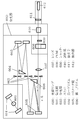
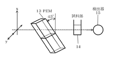
最初に、従来のECD測定法について説明する。その光学系は図5、図6に示すようなものである。光源ランプ10を出た光を、分光器11で単色光に分光し、偏光子12でY-Z平面に偏光面を有する直線偏光にして位相変調子(PEM)13に通す。このPEMは、ピエゾ効果を利用した素子で、その軸が入射する直線偏光の偏光面と45°の角度で交わるように設置されている。入射する直線偏光は、±45°方向の2つの直線偏光の和と表すことができるが、これらがこのPEMを透過するとき位相差を与えられ、変調周波数f(市販の装置では50kHz)で決まる周期で左/右に交替する円偏光となる。但しこの表現は、理解を助けるためのもので、正確でない。正確には、加わる位相差δ=δ0・sin2πftによって偏光状態が周期的に変わる。その変調の強さ、つまり変調振幅δ0は、1次のベッセル関数J1(δ0)が最大値となるδ0=1.84に設定される。これは従来装置において、CDを反映する交流成分が最大となる最適値である。位相差δが、δ=π/2=1.57のとき円偏光になるから、位相差が最大となるδ=±δ0のところでは、直線偏光が円偏光を通り越して長短が入れ替わった楕円偏光まで変調されることになる。
(Outline of conventional ECD measuring device)
First, a conventional ECD measurement method will be described. The optical system is as shown in FIGS. The light emitted from the
左右の円偏光は、試料部14に入射する。試料部14にはCDを有する試料が入っており、左右の円偏光が試料を透過すると、左と右で異なった大きさの吸収を受け、それ以降の光は、このCDに依存する強度変動を含むことになる。CD装置では検出器(市販の装置では光電子増倍管、略してPMT)15で検出した光強度を電気信号に変えているが、これは式(1)で表現される。
The left and right circularly polarized light is incident on the

ここでIl、Irは左と右の円偏光の透過光強度である。この電気信号はDCアンプおよびACアンプへ送られる。DCアンプでは、電気信号を増幅し、そこから直流成分(DC)、即ち(Il+Ir)/2が取得される。また、ACアンプで増幅された電気信号は、さらにロックインアンプへ送られる。ACアンプおよびロックインアンプにより、変調周波数fに同期した周波数の交流成分(AC)、即ち(Il−Ir)・J1(δ0)が取得される。そしてACをDCで割ったものから円二色性ΔAを式(2)で算出している。 Here, I l and I r are transmitted light intensities of left and right circularly polarized light. This electric signal is sent to a DC amplifier and an AC amplifier. In the DC amplifier, an electric signal is amplified, and a direct current component (DC), that is, (I 1 + I r ) / 2 is obtained therefrom. The electric signal amplified by the AC amplifier is further sent to the lock-in amplifier. The AC amplifier and the lock-in amplifier obtain an AC component (AC) having a frequency synchronized with the modulation frequency f, that is, (I 1 −I r ) · J 1 (δ 0 ). Then, the circular dichroism ΔA is calculated by the equation (2) from AC divided by DC.
(従来のECD測定装置のS/N比改善の問題)
最初に述べたように、一般に円二色性は非常に小さいものであり、大きな分子でもΔA/Aで高々10−2、通常は10−3から10−4であるのが普通である。そうすると、上述の従来のECD測定装置の計測では、非常に大きな直流成分に極僅かに重畳する交流成分を抽出することになり、大きな直流成分に由来する比較的大きな信号ゆらぎが支配的となっていた。このことは、さらに高いS/Nで交流成分を抽出してCDの測定感度を上げることを難しくする大きな要因となっていた。
(Problem of improving S / N ratio of conventional ECD measuring device)
As mentioned at the outset, generally the circular dichroism is very small, and even a large molecule usually has a ΔA / A of at most 10 −2 , usually 10 −3 to 10 −4 . Then, in the measurement of the conventional ECD measuring apparatus described above, an AC component that is superposed slightly on a very large DC component is extracted, and a relatively large signal fluctuation derived from the large DC component is dominant. It was. This is a major factor that makes it difficult to extract the AC component with a higher S / N and increase the CD measurement sensitivity.
(高速CD時間変化測定装置の概要)
高速CD時間変化測定装置は、高速CD時間変化測定を可能にするために、従来の偏光変調CD測定装置が改良された装置で、その基本となる構成を図7に示す。白色光の光源側から順番に、偏光子31、位相子32、試料部34、検光子35、分光器36および検出器37が光軸上に並ぶ。白色光は偏光子31によってX-Z平面に偏光面を有する直線偏光にされる。直線偏光は位相子32を透過する。この位相子32の進相軸はX軸から微小角度θだけ傾いている。また、位相子32として、適切に小さな位相差δを有するものを選ぶ。その結果、位相子32を通った後の光は、X方向の偏光成分のみではなく、Y方向の偏光成分も僅かに持つ偏光、つまり、直線偏光に近く極めて扁平率の大きい楕円偏光になっている。この楕円偏光が試料を透過すると、試料のCDにより、扁平率が変化する。この変化した楕円偏光が、先の偏光子31とクロスニコルの位置に設置した検光子35を透過する。検光子35によって楕円偏光からY軸方向の偏光成分だけが取り出される。取り出された偏光成分を分光器36に通して単色化し、その偏光強度を検出器37で検出している。このときの測定結果をI+(λ)とする。単一波長だけのデータを取得するほか、分光器36で波長に分光したあとアレイ検出器で波長ごとの複数のデータを同時に取得することで、CDスペクトルを効率的に得るシステムとしてもよい。
(Outline of high-speed CD time change measuring device)
The high-speed CD time change measuring apparatus is an apparatus improved from the conventional polarization modulation CD measuring apparatus in order to enable high-speed CD time change measurement, and its basic configuration is shown in FIG. In order from the light source side of white light, a
次に、位相子32を位相子駆動機構33によって逆に回転して角度を−θとして同様の測定を行う。このときの測定結果をI-(λ)とする。円二色性ΔAは、このI+(λ)、I-(λ)とδから、式(3)に従って計算している。
Next, the
(高速CD時間変化測定装置の問題)
従来の偏光変調CD測定装置では、偏光変調の速さによって、CD測定における時間分解の限界が決まってしまう。これに対し、上述の高速CD時間変化測定装置では位相差の変調を行わず、一定の位相差を有する位相子32を用いて、その進相軸を偏光面に対して±θの角度に合わせる。このようにして左右の円偏光に偏った状態を個々に作り、それぞれの状態で高速時間変化測定を行い、式(3)の演算によって時間変化に伴った左右の円偏光に対する吸光度の差(円二色性ΔA)を求めるものであった。その効果として、感度の向上が得られていた。
(Problem of high-speed CD time change measuring device)
In a conventional polarization modulation CD measurement apparatus, the limit of time resolution in CD measurement is determined by the speed of polarization modulation. On the other hand, the above-mentioned high-speed CD time change measuring apparatus does not modulate the phase difference, and uses the
しかし、時間変化を追わないで定常状態における円二色性を測定する場合や、時間変化を追うとしても、従来の偏光変調CD測定装置における偏光変調の速さの限界以内での時間変化で十分であり、感度の向上だけを期待する場合には、本システムをそのまま用いるだけでは満足できる測定結果が得られない。本システムでは、位相子32を機械的に動かすことで左右の円偏光に関わる偏光状態を作り出しているから、位相子32を動かすための機械部の精度が厳密でないと、そこの偏りが測定値に誤差を与えてしまう。また、位相子32を片方に設定して測定し、次に他方に動かして測定するという手順では、両測定値の間の時間的な差を、いくら高速化してもサブ秒より短くすることは困難で、この時間の違いが左右の吸光度の差をとったときの誤差の原因となり得た。
However, when measuring the circular dichroism in the steady state without following the time change, or even following the time change, the time change within the limit of the speed of the polarization modulation in the conventional polarization modulation CD measuring device is sufficient. In the case where only an improvement in sensitivity is expected, a satisfactory measurement result cannot be obtained by simply using this system as it is. In this system, the
(従来のVCD測定装置の概要)
従来のVCD測定装置も、本発明によって改良しようとする対象である。従来のVCD測定装置の基本となる構成を図8に示す。
(Outline of conventional VCD measuring device)
A conventional VCD measuring device is also an object to be improved by the present invention. The basic configuration of a conventional VCD measuring apparatus is shown in FIG.
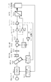
赤外光源40から発せられた白色光を、干渉計41によって干渉光にする。偏光子42は、干渉光から直線偏光を取り出し、次いでPEM43で位相変調される。それを試料部44に入射して、試料を透過した光の強度を検出器45で検出する。検出した信号はプリアンプ47で増幅され、そこから抽出されたDC成分はそのままデータ処理装置49へ送られる。また、プリアンプ47で増幅された信号はロックインアンプ48へも送られ、ロックインアンプ48がPEM43の変調周波数に同期した信号を用いてAC成分を抽出してデータ処理装置49へ送る。DC成分およびAC成分はデータ処理装置49で干渉計41の移動鏡位置に同期した時系列の信号として取り込まれる。さらにAC/DCの値が演算される。この値はCDに関係する信号列ではあるが、CDそのものではなく、CDの情報を含むインターフェログラムである。これをデータ処理用のPCに送り、そこでフーリエ変換を施してCDスペクトルを得ている。
White light emitted from the infrared
(従来のVCD測定装置の問題)
以上のVCD測定装置では、干渉計を通したインターフェログラムを計測に使っている。そこには全波長λ(波数)の光が含まれているので、位相変調の振幅δ0を波長λ毎に適切な大きさに調節することは不可能である。そのため、中心波長を適切に選択し、そこで感度が最適になるように変調振幅δ0を決めることになる。ところが、VCD測定の測定波数範囲(測定波長範囲)は、600cm−1(16μm)から5000cm−1(2μm)に亘る。その結果、ある波長の光については位相差が過大となって感度がなくなる不感帯が生じ、さらにその先では信号が逆転することも起こってしまう。逆転するのは負の係数を掛けて対処することができるとは言え、感度がなくなる不感帯については対処不能であり、位相差の変調振幅δ0を変えて測定をやり直すしかなかった。
(Problems with conventional VCD measuring devices)
In the above VCD measuring apparatus, an interferogram through an interferometer is used for measurement. Since light of all wavelengths λ (wave number) is included therein, it is impossible to adjust the phase modulation amplitude δ 0 to an appropriate size for each wavelength λ. Therefore, the center wavelength is appropriately selected, and the modulation amplitude δ 0 is determined so that the sensitivity is optimal. However, the measurement wave number range (measurement wavelength range) of VCD measurement ranges from 600 cm −1 (16 μm) to 5000 cm −1 (2 μm). As a result, there is a dead zone where the sensitivity is lost due to an excessive phase difference for light of a certain wavelength, and further, the signal is reversed after that. Although the reversal can be dealt with by applying a negative coefficient, it is impossible to deal with the dead zone in which the sensitivity is lost, and the measurement has to be repeated by changing the modulation amplitude δ 0 of the phase difference.
この事情を、1250cm−1(8μm)を中心波数と定め、ここで変調振幅δ0が最適となるように定め、他の波数での変調振幅δ0とCDの感度(効率)を与えるJ1(δ0)を見積もってみる。最適変調振幅δ0は1次のベッセル関数の極値を与えるδ0=1.84ということになる。また各波数における変調振幅はδ0=2π・Δn・d/λであり、PEMの厚さd、誘起される最大の屈折率差Δn、そして波長λで決まる。Δnは波長(波数)に依存するが、Δnを一定とみなして感度J1(δ0)を計算すると、次表のようになる。 This situation, defined as the center wavenumber 1250 cm -1 to (8 [mu] m), where determined such modulation amplitude [delta] 0 is optimal to give the sensitivity (efficiency) of the modulation amplitude [delta] 0 and CD in other wave number J 1 Try to estimate (δ 0 ). The optimum modulation amplitude δ 0 is δ 0 = 1.84 giving the extreme value of the first-order Bessel function. The modulation amplitude at each wave number is δ 0 = 2π · Δn · d / λ, and is determined by the thickness d of the PEM, the maximum refractive index difference Δn induced, and the wavelength λ. Δn depends on the wavelength (wave number), but when Δn is regarded as constant and sensitivity J 1 (δ 0 ) is calculated, the following table is obtained.
中心波数(1250cm−1)の近傍でも、波数によって感度が変るので、これを係数として補正しなければならなくなる。しかし2604cm−1は感度が零となる不感帯になり、それより高い波数帯では信号が逆転し、さらに4762cm−1も不感帯となる。さらに高い波数帯では信号の符号は正転するものの、感度は1/6程度と非常に低くなってしまう。実質的には、この条件で正常に測定できるのは2000cm−1までくらいであり、それより高波数領域を測定するには、その領域の適切な波数を中心波数に設定しなおし、変調振幅δ0の最適化をやり直すことになる。このように中心波数を一つ設定するだけでは、測定波数領域に不感帯や信号の符号の反転する波数域が生じてしまい、一度に測定可能な波数領域が限定されてしまう。 Even in the vicinity of the center wave number (1250 cm −1 ), the sensitivity changes depending on the wave number, and this must be corrected as a coefficient. However, 2604 cm -1 is a dead band where the sensitivity is zero, and the signal is reversed at a wave number band higher than that, and 4762 cm -1 is also a dead band. Further, in the higher wave number band, the sign of the signal is rotated in the normal direction, but the sensitivity is as low as about 1/6. In practice, it is possible to measure normally up to about 2000 cm −1 under this condition, and in order to measure a higher wave number region than that, an appropriate wave number in that region is reset to the center wave number, and the modulation amplitude δ 0 optimization will be redone. If only one central wave number is set in this way, a dead band or a wave number region where the sign of a signal is inverted is generated in the measured wave number region, and the wave number region that can be measured at one time is limited.
さらにVCD測定装置の場合も、電子遷移CD測定装置と同様、大きな吸収に含まれる左右円偏光に対する吸光度の僅かな差を検出しており、その比が電子遷移に較べるとさらに1/10程度しかなく、感度向上を図る上での、より大きな壁となっている。 Furthermore, in the case of the VCD measuring device, as in the case of the electronic transition CD measuring device, a slight difference in absorbance with respect to the left and right circularly polarized light included in the large absorption is detected, and the ratio is only about 1/10 compared with the electronic transition. However, it is a larger wall for improving sensitivity.
本発明は、高速CD時間変化測定装置において達成された技術をベースとする。すなわち、直線偏光に小さな位相差δを与えて扁平率が極めて大きい楕円偏光とし、その長軸方向に直交する方向に検光子をおいて、短軸方向の成分だけを検出することにより、バックグランドに相当する大きな長軸方向の成分を除く。これによって、CDを直接反映する信号だけが優先的に取り出されて、感度の向上を実現するという技術である。そして、本発明の目的は、上記の技術を、従来のECD測定装置およびVCD測定装置に適用して、これらの測定感度の向上を果たすことであり、特に、従来のVCD測定装置に適用することで、感度の向上だけでなく、測定波長範囲を限定しなければならないという問題をも解決し、振動分光が関与する全波長領域を一度に感度良く測定できる装置およびその測定方法を提供することにある。 The present invention is based on the technology achieved in a high-speed CD time variation measuring apparatus. In other words, by applying a small phase difference δ to linearly polarized light to make elliptically polarized light with an extremely large flatness, an analyzer is placed in a direction perpendicular to the major axis direction, and only the minor axis direction component is detected. The major axis component corresponding to is removed. As a result, only the signal that directly reflects the CD is preferentially extracted, and the sensitivity is improved. An object of the present invention is to improve the measurement sensitivity by applying the above technique to the conventional ECD measurement apparatus and VCD measurement apparatus, and in particular, to the conventional VCD measurement apparatus. In addition to improving sensitivity, it also solves the problem of having to limit the measurement wavelength range, and provides an apparatus and measurement method that can measure all wavelength regions involving vibration spectroscopy with high sensitivity at once. is there.
本発明の円二色性測定装置は、以下の楕円偏光変調手段、偏光強度測定手段および演算手段を備えることを特徴とする。楕円偏光変調手段は、直線偏光の互いに直交する2つの偏光成分間の位相差(δ)を変調して、長軸方向の一致する扁平率の大きい左右の楕円偏光を交互に形成する。偏光強度測定手段は、被測定試料を透過した前記左右の楕円偏光から短軸方向の偏光成分を取り出して、該偏光成分の強度変化を測定する。演算手段は、前記強度変化の直流成分(DC)、および、前記位相差の変調に同期する前記強度変化の交流成分(AC)をそれぞれ抽出して、該交流成分および該直流成分の比(AC/DC)に前記位相差の変調振幅(δ0)を掛けた値を算出して、被測定試料の円二色性を取得する。 The circular dichroism measuring apparatus of the present invention is characterized by comprising the following elliptically polarized light modulating means, polarized light intensity measuring means, and computing means. The elliptically polarized light modulating means modulates the phase difference (δ) between two orthogonally polarized light components of linearly polarized light, and alternately forms left and right elliptically polarized light having a large flatness that matches in the major axis direction. The polarization intensity measuring means takes out a polarization component in the minor axis direction from the left and right elliptically polarized light transmitted through the sample to be measured, and measures an intensity change of the polarization component. The computing means extracts the DC component (DC) of the intensity change and the AC component (AC) of the intensity change synchronized with the modulation of the phase difference, respectively, and the ratio of the AC component and the DC component (AC / DC) is multiplied by the modulation amplitude (δ 0 ) of the phase difference to obtain the circular dichroism of the sample to be measured.
この構成によれば、楕円偏光変調手段が、直線偏光を円偏光になるまで変調しないで、直線偏光を扁平率の大きい楕円偏光の状態まで変調する。よって、直線偏光から扁平率の大きい左回りと右回りの楕円偏光が交互に形成される。さらに、偏光強度測定手段が、試料を透過した左右の楕円偏光の光束を全て検出するのではなくて、左右の楕円偏光のうちの短軸方向の偏光成分だけを取り出して、その偏光成分の光束を検出し、変調に応じた偏光成分の強度変化を測定する。このようにすれば、CDを直接反映する信号だけを優先的に取り出すことができる。よって、円二色性測定の感度向上と確からしさの向上を実現できる。なお、所望の円二色性を得るには、測定された強度変化からDC成分とAC成分を抽出して、その比(AC/DC)に変調振幅(δ0)を掛ける演算を行えばよい。 According to this configuration, the elliptically polarized light modulating means does not modulate the linearly polarized light until it becomes circularly polarized light, but modulates the linearly polarized light to an elliptically polarized state having a large flatness. Therefore, left-handed and right-handed elliptically polarized light having a large aspect ratio are alternately formed from linearly polarized light. Furthermore, the polarization intensity measuring means does not detect all the left and right elliptically polarized light beams that have passed through the sample, but extracts only the short-axis polarized light component of the left and right elliptically polarized light, and the light beam of the polarized component. And the intensity change of the polarization component according to the modulation is measured. In this way, only the signal that directly reflects the CD can be preferentially extracted. Therefore, it is possible to improve the sensitivity and accuracy of circular dichroism measurement. In order to obtain the desired circular dichroism, a DC component and an AC component are extracted from the measured intensity change, and an operation of multiplying the ratio (AC / DC) by the modulation amplitude (δ 0 ) may be performed. .
また、本発明の円二色性測定装置は、以下の干渉手段、楕円偏光変調手段、偏光強度測定手段および演算手段を備えることを特徴とする。干渉手段は、光源からの赤外光を固定鏡および移動鏡に向かうように2分割し、かつ、前記固定鏡および前記移動鏡からの反射光を合成して、光路差(D)の変化に応じた干渉光を形成する。楕円偏光変調手段は、前記干渉光から直線偏光を取り出して、前記光路差(D)の変化よりも大きい変調周波数(f)で、前記直線偏光の互いに直交する2つの偏光成分間の位相差(δ)を変調して、長軸方向の一致する扁平率の大きい左右の楕円偏光を交互に形成する。偏光強度測定手段は、被測定試料を透過した前記左右の楕円偏光から短軸方向の偏光成分を取り出して、該偏光成分の強度変化を測定する。演算手段は、前記強度変化の直流成分(DC)、および、前記位相差の変調に同期する前記強度変化の交流成分(AC)をそれぞれ抽出し、該交流成分および該直流成分の比(AC/DC)を縦軸、前記光路差(D)を横軸とするインターフェログラムにフーリエ変換を施し、フーリエ変換後の値に前記位相差の変調振幅(δ0)を掛けた値を算出して、被測定試料の円二色性を取得する。 The circular dichroism measuring device of the present invention is characterized by comprising the following interference means, elliptically polarized light modulating means, polarization intensity measuring means, and computing means. The interference means divides the infrared light from the light source into two so as to go to the fixed mirror and the movable mirror, and combines the reflected light from the fixed mirror and the movable mirror to change the optical path difference (D). Corresponding interference light is formed. The elliptically polarized light modulation means extracts linearly polarized light from the interference light, and has a phase difference between two polarization components orthogonal to each other at a modulation frequency (f) greater than the change in the optical path difference (D) ( δ) is modulated to alternately form left and right elliptically polarized light having a large flatness that matches in the major axis direction. The polarization intensity measuring means takes out a polarization component in the minor axis direction from the left and right elliptically polarized light transmitted through the sample to be measured, and measures an intensity change of the polarization component. The computing means extracts the DC component (DC) of the intensity change and the AC component (AC) of the intensity change synchronized with the modulation of the phase difference, respectively, and the ratio of the AC component and the DC component (AC / DC) is the vertical axis, and the optical path difference (D) is the horizontal axis. The interferogram is subjected to Fourier transform, and a value obtained by multiplying the value after Fourier transform by the modulation amplitude (δ 0 ) of the phase difference is calculated. The circular dichroism of the sample to be measured is acquired.
この構成では、楕円偏光変調手段に入射する測定光は、干渉光である。なお、単色光が干渉計に通された場合には、その干渉光は光路差に応じたサインカーブを描く。しかし、赤外吸収の測定では、測定光は所定の波長領域の連続光であり、その干渉光は単色光が描くサインカーブの重ね合わせとなる。このような波形をインターフェログラムと呼ぶ。本発明の構成によれば、楕円偏光変調手段が、インターフェログラムを描く干渉光から直線偏光を取り出して、前述の発明と同様に、直線偏光を円偏光になるまで変調しないで、扁平率の大きい楕円偏光の状態まで変調する。よって、インターフェログラムの状態の左右の楕円偏光が交互に形成されることになる。また、前述の発明と同様に、偏光強度測定手段が、試料を透過した左右の楕円偏光の光束を全て検出するのではなくて、左右の楕円偏光のうちの短軸方向の偏光成分だけを取り出して、その偏光成分の光束を検出し、変調に応じた偏光成分の強度変化を測定する。ここで測定される偏光成分もインターフェログラムの状態であるので、所望の円二色性を得るには、測定された強度変化からDC成分とAC成分を抽出して、その比(AC/DC)にフーリエ変換を施せばよい。そして、変換後の値に変調振幅(δ0)を掛ける演算を行えばよい。従って、前述の発明と同様に、感度の向上が得られる。さらに、測定波長領域で、不感あるいは符号の反転が生じず、測定波長領域が楕円変調手段の変調振幅を設定する中心波長から限られた領域に限定されずに済む。従って、全波長領域を一度に感度良く測定することができる。 In this configuration, the measurement light incident on the elliptically polarized light modulating means is interference light. When monochromatic light is passed through the interferometer, the interference light draws a sine curve corresponding to the optical path difference. However, in the measurement of infrared absorption, the measurement light is continuous light in a predetermined wavelength region, and the interference light is a superposition of sine curves drawn by monochromatic light. Such a waveform is called an interferogram. According to the configuration of the present invention, the elliptically polarized light modulation means takes out linearly polarized light from the interference light that draws the interferogram, and does not modulate the linearly polarized light until it becomes circularly polarized light as in the above-described invention. Modulate to a state of large elliptical polarization. Therefore, left and right elliptically polarized light in an interferogram state are alternately formed. Similarly to the above-described invention, the polarization intensity measuring means does not detect all the left and right elliptically polarized light beams that have passed through the sample, but extracts only the short axis polarization component of the left and right elliptically polarized light. Then, the light flux of the polarization component is detected, and the intensity change of the polarization component corresponding to the modulation is measured. Since the polarization component measured here is also in an interferogram state, in order to obtain a desired circular dichroism, a DC component and an AC component are extracted from the measured intensity change, and the ratio (AC / DC) is obtained. ) May be subjected to Fourier transform. Then, an operation of multiplying the converted value by the modulation amplitude (δ 0 ) may be performed. Therefore, similar to the above-described invention, an improvement in sensitivity can be obtained. Furthermore, insensitivity or inversion of the sign does not occur in the measurement wavelength region, and the measurement wavelength region is not limited to the region limited from the center wavelength that sets the modulation amplitude of the elliptical modulation means. Therefore, the entire wavelength region can be measured with high sensitivity at a time.
また、楕円偏光変調手段は、入射光から直線偏光を取り出す偏光子、および、前記直線偏光を変調して左右の楕円偏光を形成する位相変調子を含む。また、偏光強度測定手段は、被測定試料を透過した前記左右の楕円偏光のうちの短軸方向の直線偏光を透過する検光子、および、この透過した直線偏光の強度を検出する検出器を含む。そして、本発明では、検光子は、偏光子に対して直交ニコルに設置されていることが好ましい。
この構成によれば、偏光子と検光子とが直交ニコルの関係にあるので、検光子が左右の楕円偏光の短軸方向の偏光成分を正確に透過させることができる。
The elliptically polarized light modulation means includes a polarizer that extracts linearly polarized light from incident light, and a phase modulator that modulates the linearly polarized light to form left and right elliptically polarized light. The polarization intensity measuring means includes an analyzer that transmits linearly polarized light in the short axis direction of the left and right elliptically polarized light that has passed through the sample to be measured, and a detector that detects the intensity of the transmitted linearly polarized light. . And in this invention, it is preferable that the analyzer is installed in crossed Nicols with respect to the polarizer.
According to this configuration, since the polarizer and the analyzer have a crossed Nicols relationship, the analyzer can accurately transmit the polarization component in the short axis direction of the left and right elliptically polarized light.
また、本発明は、所定の測定波長領域の円二色性スペクトルを取得する円二色性測定装置であって、楕円偏光変調手段の位相差(δ)の変調振幅(δ0)は、測定波長領域の全領域で1/10ラジアン以下であることが好ましい。
この構成によれば、従来のECD測定法での変調振幅がδ0=1.84ラジアンであることと比べると、変調振幅が極微小となる。よって、位相差の小さく変調精度の高い位相変調子を採用できる。
The present invention is also a circular dichroism measuring device that acquires a circular dichroism spectrum in a predetermined measurement wavelength region, wherein the modulation amplitude (δ 0 ) of the phase difference (δ) of the elliptically polarized light modulation means is measured. It is preferable that it is 1/10 radians or less in the entire wavelength region.
According to this configuration, the modulation amplitude is extremely small as compared with the modulation amplitude in the conventional ECD measurement method being δ 0 = 1.84 radians. Therefore, a phase modulator having a small phase difference and high modulation accuracy can be employed.
本発明の円二色性測定装置の基本的な構成について図1を用いて説明する。測定光学系は偏光子501、位相変調子(PEM)502、試料部503、検光子(アナライザ)504、検出器505からなり、この順に測定光500の光軸上に配置されている。
A basic configuration of the circular dichroism measuring apparatus of the present invention will be described with reference to FIG. The measurement optical system includes a
偏光子501は、測定光500からY−Z平面に偏光面を有する直線偏光を取り出すように配置されている。PEM502はその主軸をX方向から45°傾けた状態で配置されている。従来のECD測定装置では、PEMは、各測定波長において1次のベッセル関数が最大値となるδ0=1.84(ラジアン)の変調振幅を与えるようなプログラムによって駆動される。しかし、本発明では全波長領域でそれよりはるかに小さいδ0=0.1(ラジアン)、至適には0.01(ラジアン)となるよう、PEMの駆動電力をコントロールする。なお、δ0は位相変調をδ=δ0sin2πftと表したときの変調振幅を示し、予め標準試料を用いた測定によって得られ、記憶されている。
The
直線偏光はPEM502により位相差を変調される。具体的には、直線偏光の互いに直交する2つの偏光成分間の位相差(δ)がPEM502により変調される。そして、長軸方向(Y方向)の一致する扁平率の大きい左右の楕円偏光が交互に形成される。
検光子504は、試料部503の後段に偏光子501とクロスニコルとなるように設けられている。この検光子504により、試料部503の試料を透過した左右の楕円偏光から、短軸方向(X方向)の偏光成分が取り出される。そして、検出器505は、短軸方向の偏光成分の強度変化を測定する。
The phase difference of the linearly polarized light is modulated by the
The
データ処理系は、プリアンプ506、ロックインアンプ508、DCアンプ507、PEMドライバ509、A/Dコンバータ510およびデータ処理装置511から構成されている。
The data processing system includes a
検出器505で検出された光強度信号は、プリアンプ506で増幅された後、その直流成分と交流成分とが別々に増幅される。ロックインアンプ508は、PEM502の駆動周波数と同期する信号をPEMドライバ509から受けて、駆動周波数と同じ周波数成分である交流成分信号(AC)を光強度信号から抽出する。DCアンプ507は、光強度信号から直流成分信号(DC)を抽出する。直流成分信号と交流成分信号は、適当なA/Dコンバータ510で数値化されて、データ処理装置511に取り込まれる。データ処理装置511においては、CD値(ΔA)は、式(4)に従って算出される。すなわち、交流成分および直流成分の比(AC/DC)に位相差の変調振幅δ0を掛けた値を算出して、被測定試料の円二色性を取得する。
The light intensity signal detected by the
[第1実施形態]
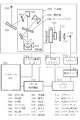
図2は本実施形態のECD測定装置の具体的な測定光学系の構成を示す光路図である。測定光学系は、光源室、分光器室、位相変調室、試料室および検出室に大別される。光源室には、光源ランプ600および集光鏡601が配置され、分光器室へ測定光を供給する。
[First Embodiment]
FIG. 2 is an optical path diagram showing the configuration of a specific measurement optical system of the ECD measurement apparatus of this embodiment. The measurement optical system is roughly classified into a light source chamber, a spectroscope chamber, a phase modulation chamber, a sample chamber, and a detection chamber. A
分光器室には、第1プリズム系および第2プリズム系の各光学素子からなる分光器602が形成され、光源からの測定光を2つの結晶石英のプリズム604、606を分光素子として単色化する。第1プリズム系は、スリット603、コリメータ鏡605および第1プリズム604からなり、光源室からの測定光を所定の波長領域の光に分光する。また、第2プリズム系も同様に、スリット603、コリメータ鏡605および第2プリズム606からなる。従来のシステムでは、第2プリズム606を偏光子としても働かせているが、これを踏襲することは好適である。すなわち、第1プリズム系からの測定光を所定の単色光に分光するとともに、直線偏光にする。直線偏光はレンズ607で集光され、位相変調室に送られる。
A
位相変調室には、PEM608およびシャッター609が配置されている。分光器602からの直線偏光は、PEM608で0.01ラジアン程度の小さな位相変調を加えられ、扁平率が大きく直線偏光に近い左右の楕円偏光となる。左右の楕円偏光は、位相差の変調周波数に応じて交互に形成され、シャッター609を通って、試料室に送られる。
A
左右の楕円偏光は試料部610を透過した後、検出室に送られる。検出室には本発明で特徴的な検光子611および検出器612が配置されている。左右の楕円偏光を検光子611に通して楕円の短軸成分である直線偏光成分を取り出し、その強度を検出器612で検出する。
The left and right elliptically polarized light passes through the
なお、偏光子として機能する第2プリズム606および出射スリット603は、測定光から取り出す偏光が紙面に平行な直線偏光となるように配置されている。一方、検光子611は、楕円偏光から紙面に垂直な偏光成分だけを取り出すよう配置されている。
Note that the
図3は本実施形態のECD測定装置の全体構成図である。ここでは、検出器612で測定された強度信号の処理システムについて説明する。検出器612で検出された光の強度信号は、プリアンプ613で増幅され、ACアンプおよびDCアンプにそれぞれ送られる。ACアンプ618は、強度信号中の交流成分を増幅する。さらにロックインアンプ619は、増幅された交流成分信号から変調周波数と同じ周波数成分を抽出する。抽出された交流成分信号はA/Dコンバータ621で数値化されてデータ処理装置622に取り込まれる。
FIG. 3 is an overall configuration diagram of the ECD measuring apparatus according to the present embodiment. Here, the processing system of the intensity signal measured by the
一方、DCアンプ620は、強度信号中の直流成分を増幅する。増幅された直流成分信号は、A/Dコンバータで数値化されデータ処理装置622に取り込まれる。また、DCアンプ620からの直流成分の一部は、差動アンプ617に取り入れられ、1Vの基準電圧と比較される。そして、PMT HTV616は、直流成分の出力が基準電圧と同じ1Vになるように、検出器612であるPMTの印加電圧をコントロールする。これにより、自動的に所望の信号レベルでAC/DCを演算することができる。
On the other hand, the
データ処理装置622の取り込んだ信号は、基本的にAC/DCであり、データ処理装置622において式(4)に示した係数(−δ0/ln10)を乗じられてCDデータとなる。 The signal captured by the data processing device 622 is basically AC / DC, and is multiplied by the coefficient (−δ 0 / ln10) shown in the equation (4) in the data processing device 622 to become CD data.
本実施形態では、PEMの駆動電力を、全波長領域で一定とするのが、システムの簡略化のためには好都合である。その結果として、変調振幅δ0は波長によって変化するので、それを係数として補正する。そうしないで、全波長領域で変調振幅δ0が一定になるようPEMの駆動電力をプログラムすることも可能である。 In the present embodiment, it is convenient for simplifying the system that the driving power of the PEM is constant in the entire wavelength region. As a result, the modulation amplitude δ 0 changes depending on the wavelength, and is corrected as a coefficient. Instead, it is also possible to program the driving power of the PEM so that the modulation amplitude δ 0 is constant over the entire wavelength region.
(δ0を実測で求める方法)
前述のように、CDを算出するには光強度の検出信号から得られたAC/DCに変調の強度に関係する係数(変調振幅δ0)を掛ける必要があり、予めこの変調振幅δ0が分かっていなければならない。この発明のきっかけとなった先行の高速CD時間変化測定装置においても、図7に示したように位相子32を機械的に動かして2つの偏光状態を作り出しており、ここでもその位相子32の位相差が既知であるは必要であった。しかし、位相子32はスタティックなものであって、エリプソメトリーなどのような既知の手段によって実測可能なものであった。ところが本発明では、この変調振幅δ0は、図1のようにPEM502を構成する結晶に振動を与え、その振動からひずみを生じさせ、そのひずみが結晶に屈折率の異方性を生起し、それが直交する2つの直線偏光に位相差を与え、それが変調の強度となっているダイナミックなものである。従って、スタティックな位相差を測定するエリプソメトリーなどのような通常の手段によっては実測できない。このダイナミックな位相変調の強度(変調振幅δ0)を、実測・確定する手段がなければ、本発明は成り立たない。この点も、先行技術と決定的に違うところである。
(Method for obtaining δ 0 by actual measurement)
As described above, it is necessary to multiply the coefficients (modulation amplitude [delta] 0) related to the intensity of the modulation AC / DC obtained from the detection signal of the light intensity to calculate the CD, advance the modulation amplitude [delta] 0 is You must know. In the preceding high-speed CD time change measuring apparatus that triggered the present invention, the
本発明のために、ダイナミックなPEM502の変調振幅δ0を実測で求める方法を説明する。このための基準試料として、スタティックな複屈折性を有する素子を用いる。このような素子としては、結晶石英やサファイヤのような透明な1軸性の結晶板が適当である。その位相差は0.1ラジアン程度のものが適当である。そして、その位相差を、波長に対するスペクトルとして、エリプソメトリーなどで実測しておく。
For the purpose of the present invention, a method for obtaining the modulation amplitude δ 0 of the
こうして位相差が求まっている基準試料を、その軸をX軸に対して45°傾けて、即ちPEMの軸に一致させる方向にして試料部503に置く。この状態で本発明の測定を行うと、直流成分はDC=1/2(偏光子を通って直線偏光になったときの光の強度を1とする)、交流成分は式(5)となる。
The reference sample whose phase difference is obtained in this way is placed on the
Δは基準試料の位相差である。これが既知であるから、目的のPEMの変調振幅δ0を、式(6)で求めることができる。 Δ is the phase difference of the reference sample. Since this is already known, the modulation amplitude δ 0 of the target PEM can be obtained by Expression (6).
[第2実施形態]
次に、本発明の第2実施形態に係るVCD測定装置について説明する。
図4は、VCD測定装置の全体構成図である。基本的な構成は、図1の光学系の構成と共通しているが、前述の第1実施形態では、測定光として分光計からの単色光を用いるのに対して、本実施形態では、測定光として干渉計からの干渉光を用いる点で相違する。
[Second Embodiment]
Next, a VCD measuring apparatus according to the second embodiment of the present invention will be described.
FIG. 4 is an overall configuration diagram of the VCD measuring apparatus. The basic configuration is the same as the configuration of the optical system in FIG. 1, but in the first embodiment, the monochromatic light from the spectrometer is used as the measurement light, whereas in this embodiment, the measurement is performed. The difference is that interference light from an interferometer is used as light.
すなわち、赤外光源700から出た光は干渉計702を通じてインターフェログラムを描く干渉光となる。干渉計702には、集光鏡701を反射した赤外光が供給される。干渉計702は、測定光を2つの光束に分割するビームスプリッタ706を有する。分割された一方の光束(ビームスプリッタの反射光)は固定鏡705を反射してビームスプリッタ706へ戻り、他方の光束(ビームスプリッタの透過光)は可動鏡707を反射して同様にビームスプリッタ706へ戻る。2つの光束はビームスプリッタ706で合成され干渉光となって出射される。干渉光は、可動鏡707の移動位置に応じた強度、すなわち、2つの光束の光路差(D)に応じた強度を有する干渉光として出射される。
That is, light emitted from the infrared
なお、干渉光を偏光子708で直線偏光のインターフェログラムとして、PEM709で位相変調を加え、試料部710に入射させることは、従来の振動CD測定装置と基本的に同じである。唯、PEMは、本発明の根幹に従って、全波数領域に亘って変調強度が0.1ラジアン以下、至適には0.01ラジアンとなる状態で稼動させる。さらに本発明では、試料部710の後に新たに検光子711を取り付けている。検光子711を透過した光は集光レンズ712で検出器713に集光される。検光子711は、前段に設けられた偏光子708とクロスニコルの状態に設置されている。
Note that the interference light is converted into a linearly polarized interferogram by the
検出器713の検出信号は、やはり従来のVCD測定装置と同様に、プリアンプ714で増幅された後、直流成分はそのままデータ処理装置718に取り込まれる。また、検出信号の交流成分はPEMの変調周波数に同期させたロックインアンプ717によって抽出され、データ処理装置718に干渉計の移動鏡の位置に同期した時系列の信号として取り込まれる。データ処理装置718は、各成分からAC/DCの値を演算する。この演算結果はCDに関係する信号列ではあるが、CDそのものではなく、インターフェログラムである。従って、これをデータ処理用のコントロールPC720に送り、そこでフーリエ変換が施されて波長(波数ν)に対するスペクトルとなる。このスペクトルに、波数νのパラメータを有する変調振幅δ0を掛けて、式(7)によりCDスペクトルを得ることができる。式中のF[ ]はフーリエ変換を表す。
The detection signal of the
[本発明の測定原理の正当性の証明]
次に、本発明のCDの測定原理が適正であることを、ジョーンズベクトル、ジョーンズ行列の手法を用いて説明する。図1の偏光子501を通過した後のY軸方向の直線偏光をジョーンズベクトルでJ1は式(8)のように表される。
[Proof of the measurement principle of the present invention]
Next, the appropriateness of the CD measurement principle of the present invention will be described using the Jones vector and Jones matrix methods. The linearly polarized light in the Y-axis direction after passing through the
さらに、変調位相差δ(=δ0sin2πft)を与えるPEM502、左右の円偏光に対してそれぞれ振幅透過率tl,trの円二色性を示す試料、X軸方向の検光子の作用を示すジョーンズ行列MPEM,MS,MAは、式(9)ように表される。
Further, the
PEM502、試料部503、検光子504を通過した後のジョーンズベクトルJ2は、J1にこれらの行列を順に左から掛けたものとなり、式(10)のようになる。
検出される信号強度は、この絶対値の2乗となり、それは式(11)のようになる。
δは小さいのでsinδ=δ、sin2δ=2δと近似でき、tlとtrの差は小さいので、(tl−tr)2=0と近似できる。式(11)は次式(12)となる。
位相差δの定義および(tl−tr)2=0の近似式から、δ2、tl・trを示す式(13)が導かれる。
上式(13)の関係を代入すると、最終的に強度Iは式(14)となる。
そうすると、直流成分DCと変調周波数fと同じ周波数の交流成分ACは、式(15)となる。
よって、CD(ΔA)と光の強度Iの関係は、式(16)で表される。
ここで、I、ΔIは、式(17)で表される。
従って、式(16)は、式(18)となって、前述の式(4)の正当性が照明された。
[変調振幅の実測方法の正当性の証明]
次に、位相差Δのスタティックな位相子を基準試料として使って、PEMの変調振幅δ0を実測する方法の根拠を、ジョーンズベクトル、ジョーンズ行列の手法を用いて説明する。
[Proof of the measurement method of modulation amplitude]
Next, the basis of a method for actually measuring the modulation amplitude δ 0 of the PEM using a static phase shifter having a phase difference Δ as a reference sample will be described using the Jones vector and Jones matrix methods.
図1において、スタティックな位相差Δを有する位相子をX軸に対して45°の方向に傾けて基準試料として使ったときのジョーンズ行列Mstdは、式(19)と表される。
これを式(10)のMSに代えて計算すると、式(20)、(21)となる。
δは小さいのでsin2δ=2δ、cos2δ=1−2δ2と近似できて式(22)となる。
前式(13)と同様、式(23)を代入すると、式(24)が得られる。
![]()
![]()
従って、式(25)となって、前述の式(6)の正当性が証明された。
(本発明のCDの検出感度について)
続いて本発明による方法が感度の点で従来法に優れることを説明する。そのために、従来の偏光変調CD測定装置と本発明による偏光変調CD測定装置で検出される直流信号および交流信号を比較する。簡単のために、偏光子を通って直線偏光になったときの光の強度を1.0として、信号強度の比較を行う。また簡単のために、試料の平均の吸光度を1.0、ΔA/Aを1/1000として比較を行う。
(Detection sensitivity of CD of the present invention)
Next, it will be explained that the method according to the present invention is superior to the conventional method in terms of sensitivity. For this purpose, a direct current signal and an alternating current signal detected by the conventional polarization modulation CD measurement apparatus and the polarization modulation CD measurement apparatus according to the present invention are compared. For the sake of simplicity, the signal intensity is compared with the intensity of the light that is linearly polarized light passing through the polarizer as 1.0. For the sake of simplicity, the comparison is performed with the average absorbance of the sample being 1.0 and ΔA / A being 1/1000.
従来法による信号強度は式(1)で表されるものとなり、直流信号DCは、DC=(Il+Ir)/2、交流信号ACは、AC=(Il−Ir)・J1(δ0)=0.5819x(Il−Ir)である。これに対して、本発明による方法は式(15)で表されるものとなり、こちらの変調振幅δ0は至適の0.01とする。 The signal intensity according to the conventional method is expressed by the equation (1). The DC signal DC is DC = (I 1 + I r ) / 2, and the AC signal AC is AC = (I 1 −I r ) · J 1. (δ 0 ) = 0.5819x (I 1 −I r ). On the other hand, the method according to the present invention is expressed by the equation (15), and the modulation amplitude δ 0 here is set to 0.01 which is optimum.
これらの条件に基づいて計算すると、表2のようになる。 Table 2 shows the calculation based on these conditions.
この計算結果から、従来法では約1.3x10⁻³の(AC/DC)を検知しなければならないのに対して、本発明では約3.7x10-2の(AC/DC)を検知すればよく、約27倍有利であることが明らかになった。 From this calculation result, it is necessary to detect (AC / DC) of about 1.3 × 10 −3 in the conventional method, whereas in the present invention, if (AC / DC) of about 3.7 × 10 −2 is detected. Well, it turned out to be about 27 times more advantageous.
この関係は、振動円二色性測定装置でも全く同じであり、振動円二色性測定装置についても従来の方法に較べ、本発明の検出感度が約27倍有利となる。 This relationship is exactly the same in the vibration circular dichroism measuring device, and the detection sensitivity of the present invention is about 27 times more advantageous for the vibration circular dichroism measuring device than in the conventional method.
(本発明のVCDの波数範囲の拡張について)
本発明による方法では、PEMの変調振幅δ0を0.01ラジアンにするのが至適である。波数1250cm−1(波長で8μm)で、この変調振幅δ0にすると、他の波数では表3のような変調振幅δ0となる。振動円二色性測定がカバーするこれら全部の波数領域で、不感あるいは符号の反転が起きる変調振幅δ0からは十分小さく、好適な感度が得られる条件で測定ができる。
(Expansion of VCD wave number range of the present invention)
In the method according to the present invention, it is optimal to set the modulation amplitude δ 0 of the PEM to 0.01 radians. In the wave number 1250 cm -1 (8 [mu] m in wavelength), when this modulation amplitude [delta] 0, the modulation amplitude [delta] 0 as shown in Table 3 in other wavenumber. In all of these wave number regions covered by the vibration circular dichroism measurement, the measurement can be performed under conditions where a suitable sensitivity can be obtained because the modulation amplitude δ 0 where insensitivity or sign inversion occurs is sufficiently small.
即ち、従来の振動円二色性測定装置では、測定波数領域がPEMの変調強度を設定する中心波数から限られた領域に限定されてしまっていたのが、本発明によってその限界が取り払われたことが判る。 That is, in the conventional vibration circular dichroism measuring apparatus, the measurement wave number region is limited to a region limited from the center wave number for setting the modulation intensity of the PEM, but the limitation is removed by the present invention. I understand that.
501、708 偏光子(楕円偏光変調手段)
502、608、709 位相変調子(楕円偏光変調手段)
504、611、711 検光子(偏光強度測定手段)
505、612、713 検出器(偏光強度測定手段)
507、620 DCアンプ(演算手段)
508、619、717 ロックインアンプ(演算手段)
511、622、718 データ処理装置(演算手段)
720 コントロールPC(演算手段)
602 分光計
606 第2プリズム(偏光子)
702 干渉計
501 and 708 Polarizer (elliptic polarization modulation means)
502, 608, 709 Phase modulator (elliptical polarization modulation means)
504, 611, 711 Analyzer (polarization intensity measuring means)
505, 612, 713 detector (polarization intensity measuring means)
507, 620 DC amplifier (calculation means)
508, 619, 717 Lock-in amplifier (calculation means)
511, 622, 718 Data processing device (calculation means)
720 Control PC (calculation means)
602
702 Interferometer
Claims (6)
被測定試料を透過した前記左右の楕円偏光から短軸方向の偏光成分を取り出して、該偏光成分の強度変化を測定する偏光強度測定手段と、
前記強度変化の直流成分(DC)、および、前記位相差の変調に同期する前記強度変化の交流成分(AC)をそれぞれ抽出して、該交流成分および該直流成分の比(AC/DC)に前記位相差の変調振幅(δ0)を掛けた値を算出して、被測定試料の円二色性を取得する演算手段と、を備えることを特徴とする円二色性測定装置。 An elliptical polarization modulator that modulates a phase difference (δ) between two polarization components orthogonal to each other of linearly polarized light to alternately form left and right elliptically polarized light having a large flatness that matches in the major axis direction;
A polarization intensity measuring means for taking out the polarization component in the minor axis direction from the left and right elliptically polarized light transmitted through the sample to be measured, and measuring the intensity change of the polarization component;
The DC component (DC) of the intensity change and the AC component (AC) of the intensity change synchronized with the modulation of the phase difference are extracted, respectively, to obtain the ratio of the AC component and the DC component (AC / DC). A circular dichroism measuring apparatus comprising: an arithmetic unit that calculates a value obtained by multiplying the modulation amplitude (δ 0 ) of the phase difference and acquires circular dichroism of the sample to be measured.
前記干渉光から直線偏光を取り出して、前記光路差(D)の変化よりも大きい変調周波数(f)で、前記直線偏光の互いに直交する2つの偏光成分間の位相差(δ)を変調して、長軸方向の一致する扁平率の大きい左右の楕円偏光を交互に形成する楕円偏光変調手段と、
被測定試料を透過した前記左右の楕円偏光から短軸方向の偏光成分を取り出して、該偏光成分の強度変化を測定する偏光強度測定手段と、
前記強度変化の直流成分(DC)、および、前記位相差の変調に同期する前記強度変化の交流成分(AC)をそれぞれ抽出し、該交流成分および該直流成分の比(AC/DC)を縦軸、前記光路差(D)を横軸とするインターフェログラムにフーリエ変換を施し、フーリエ変換後の値に前記位相差の変調振幅(δ0)を掛けた値を算出して、被測定試料の円二色性を取得する演算手段と、を備えることを特徴とする円二色性測定装置。 The infrared light from the light source is divided into two so as to go to the fixed mirror and the movable mirror, and the reflected light from the fixed mirror and the movable mirror is synthesized, and the interference light according to the change in the optical path difference (D) Interfering means to form,
The linearly polarized light is extracted from the interference light, and the phase difference (δ) between the two polarization components orthogonal to each other is modulated at a modulation frequency (f) greater than the change in the optical path difference (D). , Elliptical polarization modulation means for alternately forming left and right elliptically polarized light with a large flatness matching the major axis direction;
A polarization intensity measuring means for taking out the polarization component in the minor axis direction from the left and right elliptically polarized light transmitted through the sample to be measured, and measuring the intensity change of the polarization component;
The DC component (DC) of the intensity change and the AC component (AC) of the intensity change synchronized with the modulation of the phase difference are extracted, respectively, and the ratio of the AC component and the DC component (AC / DC) is calculated vertically. A sample to be measured is calculated by performing Fourier transform on the interferogram with the axis and the optical path difference (D) as the horizontal axis, and multiplying the value after Fourier transform by the modulation amplitude (δ 0 ) of the phase difference. And a circular dichroism measuring device.
前記楕円偏光変調手段は、入射光から直線偏光を取り出す偏光子と、前記直線偏光を変調して左右の楕円偏光を形成する位相変調子と、を含み、
前記偏光強度測定手段は、被測定試料を透過した前記左右の楕円偏光のうちの短軸方向の直線偏光を透過する検光子と、この透過した直線偏光の強度を検出する検出器と、を含み、
前記検光子は、前記偏光子に対して直交ニコルに設置されていることを特徴とする円二色性測定装置。 The measuring apparatus according to claim 1 or 2,
The elliptically polarized light modulation means includes a polarizer that extracts linearly polarized light from incident light, and a phase modulator that modulates the linearly polarized light to form left and right elliptically polarized light,
The polarization intensity measuring means includes an analyzer that transmits linearly polarized light in the short axis direction of the left and right elliptically polarized light transmitted through the sample to be measured, and a detector that detects the intensity of the transmitted linearly polarized light. ,
The circular dichroism measuring apparatus, wherein the analyzer is installed in a crossed Nicol direction with respect to the polarizer.
前記楕円偏光変調手段の位相差(δ)の変調振幅(δ0)は、前記測定波長領域の全領域で1/10ラジアン以下であることを特徴とする円二色性測定装置。 The measurement apparatus according to any one of claims 1 to 3, wherein the measurement apparatus acquires a circular dichroism spectrum in a predetermined measurement wavelength region,
The circular dichroism measuring device characterized in that the modulation amplitude (δ 0 ) of the phase difference (δ) of the elliptically polarized light modulating means is 1/10 radians or less in the entire region of the measurement wavelength region.
被測定試料を透過した前記左右の楕円偏光から短軸方向の偏光成分を取り出して、該偏光成分の強度変化を測定する偏光強度測定手段と、
前記強度変化の直流成分(DC)、および、前記位相差の変調に同期する前記強度変化の交流成分(AC)をそれぞれ抽出して、該交流成分および該直流成分の比(AC/DC)に前記位相差の変調振幅(δ0)を掛けた値を算出して、被測定試料の円二色性を取得する演算工程と、を備えることを特徴とする円二色性測定方法。 An elliptical polarization modulation step of alternately forming left and right elliptically polarized light having a large flatness that coincides in the major axis direction by modulating a phase difference (δ) between two polarization components orthogonal to each other of linearly polarized light;
A polarization intensity measuring means for taking out the polarization component in the minor axis direction from the left and right elliptically polarized light transmitted through the sample to be measured, and measuring the intensity change of the polarization component;
The DC component (DC) of the intensity change and the AC component (AC) of the intensity change synchronized with the modulation of the phase difference are extracted, respectively, to obtain the ratio of the AC component and the DC component (AC / DC). A circular dichroism measurement method comprising: a calculation step of calculating a value obtained by multiplying the modulation amplitude (δ 0 ) of the phase difference to obtain circular dichroism of the sample to be measured.
さらに、光源からの赤外光を固定鏡および移動鏡に向かうように2分割し、かつ、前記固定鏡および前記移動鏡からの反射光を合成して、光路差(D)の変化に応じた干渉光を形成する干渉光形成工程を備え、
前記楕円偏光変調工程では、前記干渉光から直線偏光を取り出して、前記光路差(D)の変化よりも大きい変調周波数(f)で、前記直線偏光の互いに直交する2つの偏光成分間の位相差(δ)を変調し、
前記演算工程では、前記強度変化の直流成分(DC)、および、前記位相差の変調に同期する前記強度変化の交流成分(AC)をそれぞれ抽出して、該交流成分および該直流成分の比(AC/DC)を縦軸、前記光路差(D)を横軸とするインターフェログラムにフーリエ変換を施し、フーリエ変換後の値に前記位相差の変調振幅(δ0)を掛けた値を算出して、被測定試料の円二色性を取得することを特徴とする円二色性測定方法。 The measurement method according to claim 5, wherein
Further, the infrared light from the light source is divided into two so as to go to the fixed mirror and the movable mirror, and the reflected light from the fixed mirror and the movable mirror is synthesized to respond to the change in the optical path difference (D). An interference light forming step for forming interference light;
In the elliptical polarization modulation step, linearly polarized light is extracted from the interference light, and a phase difference between two polarization components orthogonal to each other at a modulation frequency (f) larger than a change in the optical path difference (D). Modulate (δ),
In the calculation step, the direct current component (DC) of the intensity change and the alternating current component (AC) of the intensity change synchronized with the modulation of the phase difference are respectively extracted, and the ratio of the alternating current component and the direct current component ( AC / DC) is the vertical axis, and the optical path difference (D) is the horizontal axis. The interferogram is subjected to Fourier transform, and the value obtained by multiplying the value after Fourier transform by the modulation amplitude (δ 0 ) of the phase difference is calculated. Then, the circular dichroism measuring method characterized by acquiring circular dichroism of a sample to be measured.
Priority Applications (1)
| Application Number | Priority Date | Filing Date | Title |
|---|---|---|---|
| JP2011067514A JP5722094B2 (en) | 2011-03-25 | 2011-03-25 | Circular dichroism measuring apparatus and circular dichroism measuring method |
Applications Claiming Priority (1)
| Application Number | Priority Date | Filing Date | Title |
|---|---|---|---|
| JP2011067514A JP5722094B2 (en) | 2011-03-25 | 2011-03-25 | Circular dichroism measuring apparatus and circular dichroism measuring method |
Publications (2)
| Publication Number | Publication Date |
|---|---|
| JP2012202812A true JP2012202812A (en) | 2012-10-22 |
| JP5722094B2 JP5722094B2 (en) | 2015-05-20 |
Family
ID=47183984
Family Applications (1)
| Application Number | Title | Priority Date | Filing Date |
|---|---|---|---|
| JP2011067514A Active JP5722094B2 (en) | 2011-03-25 | 2011-03-25 | Circular dichroism measuring apparatus and circular dichroism measuring method |
Country Status (1)
| Country | Link |
|---|---|
| JP (1) | JP5722094B2 (en) |
Cited By (9)
| Publication number | Priority date | Publication date | Assignee | Title |
|---|---|---|---|---|
| JP2014182076A (en) * | 2013-03-21 | 2014-09-29 | Jasco Corp | Modulation signal detector for photoelastic modulator |
| US20170191928A1 (en) * | 2014-06-02 | 2017-07-06 | Hamamatsu Photonics K.K. | Circular dichroism measuring method and circular dichroism measuring device |
| JP2017138129A (en) * | 2016-02-01 | 2017-08-10 | 学校法人慶應義塾 | Polarization measurement device using dual-comb spectroscopy, and polarization measurement method |
| WO2017175770A1 (en) * | 2016-04-05 | 2017-10-12 | 株式会社分光計測 | Method for observing dynamic physical property of biological tissue, and device for observing dynamic physical property of biological tissue |
| WO2017175773A1 (en) * | 2016-04-05 | 2017-10-12 | 株式会社分光計測 | Method for observing dynamic physical property of biological tissue, and device for observing dynamic physical property of biological tissue |
| WO2017209079A1 (en) * | 2016-05-30 | 2017-12-07 | 株式会社ニコン | Observing device and observing method |
| JP6351893B1 (en) * | 2018-02-26 | 2018-07-04 | 日本分光株式会社 | Phase difference control device |
| JP2020148723A (en) * | 2019-03-15 | 2020-09-17 | 日本分光株式会社 | Circular dichroism measuring device and method for measuring circular dichroism |
| WO2022064714A1 (en) * | 2020-09-28 | 2022-03-31 | 日本分光株式会社 | Infrared circular dichroism measurement device |
Families Citing this family (1)
| Publication number | Priority date | Publication date | Assignee | Title |
|---|---|---|---|---|
| CN110736544B (en) * | 2019-10-08 | 2021-11-30 | 中国科学院上海光学精密机械研究所 | Shear amount calibration device and calibration method for transverse shear interference wavefront sensor |
Citations (8)
| Publication number | Priority date | Publication date | Assignee | Title |
|---|---|---|---|---|
| JPH02183142A (en) * | 1989-01-08 | 1990-07-17 | Japan Spectroscopic Co | Spectropolarimeter |
| JPH02242137A (en) * | 1989-03-15 | 1990-09-26 | Japan Spectroscopic Co | Double refraction analysis apparatus |
| JPH09236542A (en) * | 1995-12-28 | 1997-09-09 | Jasco Corp | Optical active body detecting device |
| JPH10325840A (en) * | 1997-05-23 | 1998-12-08 | Seiko Instr Inc | Scanning near-field microscope utilizing polarization |
| US20030030805A1 (en) * | 1997-07-28 | 2003-02-13 | Oakberg Theodore C. | Measurement of waveplate retardation using a photoelastic modulator |
| JP2005043100A (en) * | 2003-07-23 | 2005-02-17 | Jasco Corp | Infrared circular dichroism spectrophotometer |
| US20050102482A1 (en) * | 2002-01-14 | 2005-05-12 | Raidcore, Inc. | Method and system for configuring RAID subsystems with block I/O commands and block I/O path |
| US20110149282A1 (en) * | 2009-12-18 | 2011-06-23 | Rudolph Research Analytical | Polarimeter and Polarimetry Method |
-
2011
- 2011-03-25 JP JP2011067514A patent/JP5722094B2/en active Active
Patent Citations (8)
| Publication number | Priority date | Publication date | Assignee | Title |
|---|---|---|---|---|
| JPH02183142A (en) * | 1989-01-08 | 1990-07-17 | Japan Spectroscopic Co | Spectropolarimeter |
| JPH02242137A (en) * | 1989-03-15 | 1990-09-26 | Japan Spectroscopic Co | Double refraction analysis apparatus |
| JPH09236542A (en) * | 1995-12-28 | 1997-09-09 | Jasco Corp | Optical active body detecting device |
| JPH10325840A (en) * | 1997-05-23 | 1998-12-08 | Seiko Instr Inc | Scanning near-field microscope utilizing polarization |
| US20030030805A1 (en) * | 1997-07-28 | 2003-02-13 | Oakberg Theodore C. | Measurement of waveplate retardation using a photoelastic modulator |
| US20050102482A1 (en) * | 2002-01-14 | 2005-05-12 | Raidcore, Inc. | Method and system for configuring RAID subsystems with block I/O commands and block I/O path |
| JP2005043100A (en) * | 2003-07-23 | 2005-02-17 | Jasco Corp | Infrared circular dichroism spectrophotometer |
| US20110149282A1 (en) * | 2009-12-18 | 2011-06-23 | Rudolph Research Analytical | Polarimeter and Polarimetry Method |
Cited By (24)
| Publication number | Priority date | Publication date | Assignee | Title |
|---|---|---|---|---|
| JP2014182076A (en) * | 2013-03-21 | 2014-09-29 | Jasco Corp | Modulation signal detector for photoelastic modulator |
| US10330590B2 (en) * | 2014-06-02 | 2019-06-25 | Hamamatsu Photonics K.K. | Circular dichroism measuring method and circular dichroism measuring device |
| US20170191928A1 (en) * | 2014-06-02 | 2017-07-06 | Hamamatsu Photonics K.K. | Circular dichroism measuring method and circular dichroism measuring device |
| US10663391B2 (en) | 2014-06-02 | 2020-05-26 | Hamamatsu Photonics K.K. | Circular dichroism measuring method and circular dichroism measuring device |
| JP2017138129A (en) * | 2016-02-01 | 2017-08-10 | 学校法人慶應義塾 | Polarization measurement device using dual-comb spectroscopy, and polarization measurement method |
| WO2017175770A1 (en) * | 2016-04-05 | 2017-10-12 | 株式会社分光計測 | Method for observing dynamic physical property of biological tissue, and device for observing dynamic physical property of biological tissue |
| WO2017175773A1 (en) * | 2016-04-05 | 2017-10-12 | 株式会社分光計測 | Method for observing dynamic physical property of biological tissue, and device for observing dynamic physical property of biological tissue |
| JPWO2017175773A1 (en) * | 2016-04-05 | 2019-05-16 | 株式会社分光計測 | Method and apparatus for observing physical property of physical tissue |
| JPWO2017175770A1 (en) * | 2016-04-05 | 2019-06-27 | 株式会社分光計測 | Method and apparatus for observing physical property of physical tissue |
| JP7078956B2 (en) | 2016-04-05 | 2022-06-01 | 株式会社分光計測 | Biotissue mechanical property observation method and biotissue mechanical property observation device |
| US10718708B2 (en) | 2016-04-05 | 2020-07-21 | Advanced Bio-Spectroscopy Co., Ltd | Method for observing dynamic physical property of biological tissue and device for observing dynamic physical property of biological tissue |
| WO2017209079A1 (en) * | 2016-05-30 | 2017-12-07 | 株式会社ニコン | Observing device and observing method |
| JPWO2017209079A1 (en) * | 2016-05-30 | 2019-03-28 | 株式会社ニコン | Observation apparatus and observation method |
| US10914676B2 (en) | 2016-05-30 | 2021-02-09 | Nikon Corporation | Observation apparatus and observation method |
| JP6351893B1 (en) * | 2018-02-26 | 2018-07-04 | 日本分光株式会社 | Phase difference control device |
| JP2019148430A (en) * | 2018-02-26 | 2019-09-05 | 日本分光株式会社 | Phase difference controller |
| WO2020188841A1 (en) | 2019-03-15 | 2020-09-24 | 日本分光株式会社 | Circular dichroism measurement device and circular dichroism measurement method |
| JP2020148723A (en) * | 2019-03-15 | 2020-09-17 | 日本分光株式会社 | Circular dichroism measuring device and method for measuring circular dichroism |
| CN113574362A (en) * | 2019-03-15 | 2021-10-29 | 日本分光株式会社 | Circular dichroism measuring device and circular dichroism measuring method |
| EP3940368A4 (en) * | 2019-03-15 | 2022-12-14 | JASCO Corporation | Circular dichroism measurement device and circular dichroism measurement method |
| US11879833B2 (en) | 2019-03-15 | 2024-01-23 | Jasco Corporation | Circular dichroism measurement device and circular dichroism measurement method |
| WO2022064714A1 (en) * | 2020-09-28 | 2022-03-31 | 日本分光株式会社 | Infrared circular dichroism measurement device |
| JPWO2022064714A1 (en) * | 2020-09-28 | 2022-03-31 | ||
| JP7170367B2 (en) | 2020-09-28 | 2022-11-14 | 日本分光株式会社 | Infrared circular dichroism measuring device |
Also Published As
| Publication number | Publication date |
|---|---|
| JP5722094B2 (en) | 2015-05-20 |
Similar Documents
| Publication | Publication Date | Title |
|---|---|---|
| JP5722094B2 (en) | Circular dichroism measuring apparatus and circular dichroism measuring method | |
| US9200998B2 (en) | Method and apparatus for ellipsometry measurement | |
| US7889339B1 (en) | Complementary waveplate rotating compensator ellipsometer | |
| JP4455024B2 (en) | Birefringence measuring device | |
| US20090033936A1 (en) | Optical characteristic measuring apparatus and optical characteristic measuring method | |
| CN101473212A (en) | Focused-beam ellipsometer | |
| KR101798957B1 (en) | Apparatus and method for snapshot interferometric spectro-polarimetry | |
| JP4625908B2 (en) | Polarization modulation imaging ellipsometer | |
| KR101267119B1 (en) | Measuring instrument and measuring method | |
| JP7316355B2 (en) | Vertical Incidence Ellipsometer and Method for Measuring Optical Properties of Specimen Using Same | |
| EP2610665B1 (en) | Depolarizer and circular dichroism spectrometer using the same | |
| JP4747304B2 (en) | Measuring device, measuring method, and characteristic measuring unit | |
| JP3844222B2 (en) | Birefringence measuring device | |
| JP2007232550A (en) | Optical characteristic measuring instrument and optical characteristic measuring method | |
| CN107219191B (en) | Oblique incidence light reflection difference device based on Fourier transform | |
| KR102139995B1 (en) | Normal-incidence and non-normal-incidence combination ellipsometer and method for measuring optical properties of the sample using the same | |
| WO2010005703A1 (en) | Rapid acquisition ellipsometry | |
| US20190271639A1 (en) | Circular dichroism measuring method and circular dichroism measuring device | |
| JP5555099B2 (en) | Circular dichroism measuring device | |
| JP3341928B2 (en) | Dichroic dispersion meter | |
| RU2560148C1 (en) | METHOD OF MEASURING MAGNETOOPTICAL EFFECTS in situ | |
| JP2015114266A (en) | Polarization analyzing apparatus | |
| US20230080312A1 (en) | Non-linear single-molecule fret and polarization-sweep single-molecule microscopy | |
| JP2002098638A (en) | Apparatus for measuring degree of fluorescence polarization | |
| JP2006071458A (en) | Double refraction phase difference measuring device and double refraction phase difference measuring method |
Legal Events
| Date | Code | Title | Description |
|---|---|---|---|
| A621 | Written request for application examination |
Free format text: JAPANESE INTERMEDIATE CODE: A621 Effective date: 20140130 |
|
| A977 | Report on retrieval |
Free format text: JAPANESE INTERMEDIATE CODE: A971007 Effective date: 20140813 |
|
| A131 | Notification of reasons for refusal |
Free format text: JAPANESE INTERMEDIATE CODE: A131 Effective date: 20140826 |
|
| A521 | Request for written amendment filed |
Free format text: JAPANESE INTERMEDIATE CODE: A523 Effective date: 20141016 |
|
| TRDD | Decision of grant or rejection written | ||
| A01 | Written decision to grant a patent or to grant a registration (utility model) |
Free format text: JAPANESE INTERMEDIATE CODE: A01 Effective date: 20150310 |
|
| A61 | First payment of annual fees (during grant procedure) |
Free format text: JAPANESE INTERMEDIATE CODE: A61 Effective date: 20150325 |
|
| R150 | Certificate of patent or registration of utility model |
Ref document number: 5722094 Country of ref document: JP Free format text: JAPANESE INTERMEDIATE CODE: R150 |
|
| R250 | Receipt of annual fees |
Free format text: JAPANESE INTERMEDIATE CODE: R250 |
|
| R250 | Receipt of annual fees |
Free format text: JAPANESE INTERMEDIATE CODE: R250 |
|
| R250 | Receipt of annual fees |
Free format text: JAPANESE INTERMEDIATE CODE: R250 |
|
| R250 | Receipt of annual fees |
Free format text: JAPANESE INTERMEDIATE CODE: R250 |
|
| R250 | Receipt of annual fees |
Free format text: JAPANESE INTERMEDIATE CODE: R250 |
|
| R250 | Receipt of annual fees |
Free format text: JAPANESE INTERMEDIATE CODE: R250 |