KR101267119B1 - Measuring instrument and measuring method - Google Patents
Measuring instrument and measuring method Download PDFInfo
- Publication number
- KR101267119B1 KR101267119B1 KR1020087022194A KR20087022194A KR101267119B1 KR 101267119 B1 KR101267119 B1 KR 101267119B1 KR 1020087022194 A KR1020087022194 A KR 1020087022194A KR 20087022194 A KR20087022194 A KR 20087022194A KR 101267119 B1 KR101267119 B1 KR 101267119B1
- Authority
- KR
- South Korea
- Prior art keywords
- light
- light intensity
- intensity information
- retarder
- analysis target
- Prior art date
Links
- 238000000034 method Methods 0.000 title claims description 122
- 238000004458 analytical method Methods 0.000 claims abstract description 192
- 230000010287 polarization Effects 0.000 claims abstract description 129
- 238000012545 processing Methods 0.000 claims abstract description 84
- 230000008569 process Effects 0.000 claims description 50
- 238000001514 detection method Methods 0.000 claims description 15
- 238000000691 measurement method Methods 0.000 claims description 11
- 238000001228 spectrum Methods 0.000 claims description 6
- 239000004973 liquid crystal related substance Substances 0.000 abstract description 5
- 230000003287 optical effect Effects 0.000 description 62
- 238000005259 measurement Methods 0.000 description 43
- 238000002474 experimental method Methods 0.000 description 27
- 238000010586 diagram Methods 0.000 description 19
- 238000012795 verification Methods 0.000 description 13
- 239000011159 matrix material Substances 0.000 description 10
- 230000006870 function Effects 0.000 description 9
- 238000011156 evaluation Methods 0.000 description 8
- 238000009826 distribution Methods 0.000 description 4
- RDYMFSUJUZBWLH-UHFFFAOYSA-N endosulfan Chemical compound C12COS(=O)OCC2C2(Cl)C(Cl)=C(Cl)C1(Cl)C2(Cl)Cl RDYMFSUJUZBWLH-UHFFFAOYSA-N 0.000 description 4
- 229910052736 halogen Inorganic materials 0.000 description 4
- 150000002367 halogens Chemical class 0.000 description 4
- CPBQJMYROZQQJC-UHFFFAOYSA-N helium neon Chemical compound [He].[Ne] CPBQJMYROZQQJC-UHFFFAOYSA-N 0.000 description 4
- 239000000463 material Substances 0.000 description 4
- 239000010445 mica Substances 0.000 description 3
- 229910052618 mica group Inorganic materials 0.000 description 3
- 238000011144 upstream manufacturing Methods 0.000 description 3
- 230000006866 deterioration Effects 0.000 description 2
- 238000011549 displacement method Methods 0.000 description 2
- 239000012769 display material Substances 0.000 description 2
- 230000000694 effects Effects 0.000 description 2
- 230000007274 generation of a signal involved in cell-cell signaling Effects 0.000 description 2
- 238000012986 modification Methods 0.000 description 2
- 230000004048 modification Effects 0.000 description 2
- 230000008859 change Effects 0.000 description 1
- 238000006243 chemical reaction Methods 0.000 description 1
- 238000011161 development Methods 0.000 description 1
- 239000006185 dispersion Substances 0.000 description 1
- 238000000572 ellipsometry Methods 0.000 description 1
- 230000022233 establishment of spindle orientation Effects 0.000 description 1
- 230000006872 improvement Effects 0.000 description 1
- 238000007689 inspection Methods 0.000 description 1
- 239000013307 optical fiber Substances 0.000 description 1
- 229920000620 organic polymer Polymers 0.000 description 1
- 229920000642 polymer Polymers 0.000 description 1
- 229920006254 polymer film Polymers 0.000 description 1
- 239000002861 polymer material Substances 0.000 description 1
- 238000003908 quality control method Methods 0.000 description 1
- 238000012827 research and development Methods 0.000 description 1
- 230000009466 transformation Effects 0.000 description 1
Images

Classifications
-
- G—PHYSICS
- G01—MEASURING; TESTING
- G01N—INVESTIGATING OR ANALYSING MATERIALS BY DETERMINING THEIR CHEMICAL OR PHYSICAL PROPERTIES
- G01N21/00—Investigating or analysing materials by the use of optical means, i.e. using sub-millimetre waves, infrared, visible or ultraviolet light
- G01N21/17—Systems in which incident light is modified in accordance with the properties of the material investigated
- G01N21/21—Polarisation-affecting properties
-
- G—PHYSICS
- G01—MEASURING; TESTING
- G01J—MEASUREMENT OF INTENSITY, VELOCITY, SPECTRAL CONTENT, POLARISATION, PHASE OR PULSE CHARACTERISTICS OF INFRARED, VISIBLE OR ULTRAVIOLET LIGHT; COLORIMETRY; RADIATION PYROMETRY
- G01J4/00—Measuring polarisation of light
- G01J4/04—Polarimeters using electric detection means
-
- G—PHYSICS
- G01—MEASURING; TESTING
- G01N—INVESTIGATING OR ANALYSING MATERIALS BY DETERMINING THEIR CHEMICAL OR PHYSICAL PROPERTIES
- G01N21/00—Investigating or analysing materials by the use of optical means, i.e. using sub-millimetre waves, infrared, visible or ultraviolet light
- G01N21/17—Systems in which incident light is modified in accordance with the properties of the material investigated
- G01N21/21—Polarisation-affecting properties
- G01N21/23—Bi-refringence
Abstract
계측 장치는, 분석의 대상인 분석 대상광의 편광 상태를 계측하는 장치로서, 리타더(22) 및 검광자(24)를 포함하는 변조부(20)와, 변조부에서 분석 대상광을 변조시킴에 의해 얻어지는 변조광의 광강도 정보를 취득하는 광강도 정보 취득부(30)와, 광강도 정보에 의거하여 분석 대상광의 편광 특성 요소를 산출하는 연산 처리부(50)를 포함한다. 광강도 정보 취득부는, 리타더 및 검광자의 주축 방위의 적어도 한쪽이 다른 제 1 내지 제 N의 주축 방위 조건으로 설정된 변조부에서 분석 대상광을 변조시킴에 의해 얻어지는 제 1 내지 제 N의 변조광의 광강도 정보를 취득한다. 연산 처리부는, 제 1 내지 제 N의 변조광의 광강도의 이론식과, 제 1 내지 제 N의 광강도 정보에 의거하여, 편광 특성 요소 산출 처리를 행한다.The measuring device is a device for measuring the polarization state of the analysis target light to be analyzed, and modulates the analysis target light by the modulator 20 including the retarder 22 and the analyzer 24, and the modulator. And a light intensity information acquisition unit 30 for acquiring light intensity information of the modulated light obtained, and an arithmetic processing unit 50 for calculating the polarization characteristic element of the analysis target light based on the light intensity information. The light intensity information acquiring unit is a light of the first to Nth modulated light obtained by modulating the analysis target light in a modulator in which at least one of the main axis orientations of the retarder and the analyzer is set to the first to Nth main axis orientation conditions. Obtain strength information. The calculation processing unit performs polarization characteristic element calculation processing based on the theoretical formula of the light intensity of the first to Nth modulated light and the light intensity information of the first to Nth.
액정, 편광, 광강도 Liquid crystal, polarization, light intensity
Description
본 발명은, 분석의 대상인 분석 대상광의 편광 상태를 계측하는 계측 장치, 및 분석 대상광의 편광 상태를 계측하는 계측 방법에 관한 것이다.The present invention relates to a measurement device for measuring the polarization state of the analysis target light, which is the object of analysis, and a measurement method for measuring the polarization state of the analysis target light.
근래에는, 새로운 액정 표시 재료의 개발이 왕성하게 행하여지고 있다. 이에 수반하여, 제품 검사의 계측법에도 고정밀화가 요구되고 있다. 액정 표시 재료용의 고분자 필름으로서 원편광(圓偏光) 필름이 있다. 이것은, 액정이 갖는 복굴절이나 선광성(旋光性)에 의한 협시야각화(狹視野角化)나 착색에 의한 제품 열화를 보상할 수 있다. 또한, 복굴절이나 선광(旋光)은, 파장 의존성을 갖기 때문에, 파장마다의 평가가 필요하다. 그 평가 방법으로서, 종래, 타원률(楕圓率) 측정에는 회전검광자법이나 회전위상자법이 이용되어 왔다. 또한, 이들의 기술을 나타내는 문헌으로서, 일본 특허공개 2005-292028호 공보나, R.M.A.Azaam, Ellipsometry and polarized light, (1976)가 알려져 있다.In recent years, development of a new liquid crystal display material is actively performed. In connection with this, high precision is calculated | required also in the measuring method of product inspection. There is a circularly polarized film as a polymer film for liquid crystal display materials. This can compensate for narrow viewing angle deterioration due to birefringence and opticality of the liquid crystal and deterioration of the product due to coloration. In addition, since birefringence and linear light have wavelength dependence, evaluation for every wavelength is necessary. As the evaluation method, conventionally, the rotational analyzer method and the rotational displacement method have been used for ellipticity measurement. In addition, Japanese Patent Laid-Open No. 2005-292028 and R.M.A.Azaam, Ellipsometry and polarized light, (1976) are known as documents showing these techniques.
그러나, 회전검광자법에서는, 타원률이 역(逆)사인 함수로 주어지기 때문에, 측정 시료의 복굴절 위상차가 90도 부근인 경우에 정밀도가 나빠진다. 또한, 회전위상자법에서는, 측정하는 파장에 맞추어서 위상자(位相子)를 교환할 필요가 있기 때문에, 파장마다의 평가를 효율적으로 행하는 것이 어려웠다.However, in the rotational analyzer method, since the ellipticity is given as an inverse sine function, the accuracy becomes poor when the birefringence phase difference of the measurement sample is about 90 degrees. In addition, in the rotational displacement method, it is necessary to replace the phase rulers in accordance with the wavelength to be measured, so that it is difficult to efficiently perform the evaluation for each wavelength.
본 발명의 목적은, 분석의 대상인 분석 대상광의 편광 상태를, 파장마다 위상자를 교환하는 일 없이, 고정밀도로 분석하는 것이 가능한 계측 장치 및 계측 방법을 제공하는 데 있다.An object of the present invention is to provide a measuring device and a measuring method which can analyze the polarization state of the analysis target light, which is the object of analysis, with high accuracy without exchanging the retarder for each wavelength.
(1) 본 발명에 관한 계측 장치는,(1) The measuring device according to the present invention,
분석의 대상인 분석 대상광의 편광 상태를 계측하는 계측 장치로서,As a measuring device for measuring the polarization state of the analysis target light to be analyzed,
회전 가능하게 구성된 리타더 및 검광자를 포함하는, 상기 분석 대상광을 변조시키는 변조부와,A modulator configured to modulate the light to be analyzed, including a retarder and an analyzer configured to be rotatable;
상기 변조부에서 상기 분석 대상광을 변조시킴에 의해 얻어지는 변조광의 광강도 정보를 취득하는 광강도 정보 취득부와,A light intensity information acquisition unit for acquiring light intensity information of modulated light obtained by modulating the analysis target light in the modulator;
상기 변조광의 광강도 정보에 의거하여 상기 분석 대상광의 편광 특성 요소를 산출하는 연산 처리를 행하는 연산 처리부를 포함하고,An arithmetic processing unit that performs arithmetic processing for calculating a polarization characteristic element of the analysis target light based on the light intensity information of the modulated light,
상기 변조부는,The modulator,
상기 분석 대상광이, 상기 리타더를 투과하고, 그 후, 상기 검광자를 투과하도록 구성되어 이루어지고,The light to be analyzed passes through the retarder, and is then configured to pass through the analyzer,
상기 광강도 정보 취득부는,The light intensity information acquisition unit,
상기 리타더의 주축 방위와 상기 검광자의 주축 방위가 소여(所與)된 관계를 충족시키고, 또한 상기 리타더 및 상기 검광자의 주축 방위의 적어도 한쪽이 다른 제 1 내지 제 N(N은 2 이상의 정수)의 주축 방위 조건으로 설정된 상기 변조부에서 상기 분석 대상광을 변조시킴에 의해 얻어지는, 제 1 내지 제 N의 변조광의 광강도 정보를 취득하고,A first to Nth (N is an integer of 2 or more) satisfying a relationship in which the main axis bearing of the retarder and the main axis bearing of the analyzer are satisfied, and at least one of the main axis bearings of the retarder and the analyzer is different Obtains the light intensity information of the first to Nth modulated light obtained by modulating the light to be analyzed in the modulator set to the principal axis orientation condition of
상기 연산 처리부는,The calculation processing unit,
상기 분석 대상광의 편광 특성 요소 및 상기 변조부의 주축 방위 조건을 반영한 상기 제 1 내지 제 N의 변조광의 광강도의 이론식과, 상기 제 1 내지 제 N의 변조광의 광강도 정보에 의거하여, 상기 편광 특성 요소를 산출하는 처리를 행한다.The polarization characteristic based on a theoretical formula of the light intensity of the first to Nth modulated light reflecting the polarization characteristic element of the analysis target light and the principal axis orientation condition of the modulator and the light intensity information of the first to Nth modulated light. The process of calculating an element is performed.
본 발명에 관한 계측 장치에서는, 광강도 정보 취득부에서 취득되는 변조광의 광강도의 이론식은, 분석 대상광의 편광 특성 요소 및 변조부의 주축 방위 조건을 반영하고 있다. 그 때문에, 변조광의 광강도의 이론식과 실측치를 대응시킴에 의해, 분석 대상광의 편광 특성 요소를 산출하는 것이 가능해진다.In the measuring device according to the present invention, the theoretical formula of the light intensity of the modulated light acquired by the light intensity information acquisition unit reflects the polarization characteristic element of the analysis target light and the main axis orientation condition of the modulating unit. Therefore, by matching the theoretical formula of the light intensity of modulated light and the measured value, it becomes possible to calculate the polarization characteristic element of the analysis object light.
즉, 본 발명에 의하면, 분석의 대상인 분석 대상광의 편광 상태를, 분석 대상광의 파장마다 위상자를 교환하는 일 없이, 고정밀도로 분석하는 것이 가능한 계측 장치를 제공하는 것이 가능해진다. 또한, 본 발명에 의하면, 리타더 및 검광자를 회전시키는 것만의, 단순한 구동계만으로 계측 장치를 구성할 수 있기 때문에, 계측 효율 및 계측 정밀도가 높은 계측 장치를 제공하는 것이 가능해진다.That is, according to this invention, it becomes possible to provide the measuring device which can analyze the polarization state of the analysis target light which is the object of analysis with high precision, without exchanging a phaser for every wavelength of the analysis target light. Moreover, according to this invention, since a measuring device can be comprised only by a simple drive system only by rotating a retarder and an analyzer, it becomes possible to provide the measuring device with high measurement efficiency and measurement accuracy.
또한, 변조광의 광강도 정보는, 변조광을 해석 처리하여 얻을 수 있다. 그리고, 변조부가 충족시켜야 할 제 1 내지 제 N의 주축 방위 조건은, 광강도 정보의 해석 방법에 맞추어서 선택할 수 있다. 현재, 광강도 정보의 해석 방법으로서, 푸리에 해석법 등의 여러가지의 방법이 알려져 있는데, 해석 방법에 따라, 해석에 적합한 데이터가 달라지는 일이 있다. 그 때문에, 본 발명에서는, 제 1 내지 제 N의 주축 방위 조건을, 선택하는 해석 방법에 적합한 데이터를 취득하는 것이 가능한 설정으로 하여도 좋다.The light intensity information of the modulated light can be obtained by analyzing the modulated light. The first to Nth main axis orientation conditions to be satisfied by the modulator can be selected in accordance with the analysis method of the light intensity information. Currently, various methods, such as a Fourier analysis method, are known as an analysis method of the light intensity information, but data suitable for analysis may vary depending on the analysis method. Therefore, in this invention, you may make it the setting which can acquire the data suitable for the analysis method which selects the 1st-Nth main axis orientation conditions.
단, 리타더 및 검광자의 주축 방위를 θ1, θ2로 두면, θ1, θ2는, 2θ1-2θ2≠0, 또한 4θ1-2θ2≠0, 또한 2θ1-2θ2≠4θ1-2θ2≠2θ2라는 조건을 충족시키고 있어도 좋고, 이에 의하면, 푸리에 해석 처리에 의해, 스톡스 파라미터의 모든 요소를 산출하는 것이 가능해진다.However, if the main axis orientations of the retarder and the analyzer are θ 1 and θ 2 , θ 1 and θ 2 are 2θ 1 -2θ 2 ≠ 0, 4θ 1 -2θ 2 ≠ 0, and 2θ 1 -2θ 2 ≠ 4θ The condition of 1 -2θ 2 ? 2θ 2 may be satisfied, and accordingly, all elements of the Stokes parameter can be calculated by the Fourier analysis process.
본 발명에 관한 계측 장치는, 광원과 수광부를 포함하고, 광원과 수광부를 잇는 광로상에 변조부가 배치된 광학계를 포함하는 구성을 하고 있어도 좋다. 이 때, 광학계는, 광로상으로서 광원과 변조부 사이에 배치된 시료를 포함하고 있어도 좋다. 그리고, 계측 장치는, 시료의 광학 특성 요소(복굴절 위상차, 주축 방위, 선광성, 또는, 스톡스 파라미터, 뮬러 행렬 요소, 존스 행렬 요소 등)를 계측하는 계측 장치로서 구성되어 있어도 좋고, 시료에 입사되는 입사광의 편광 상태를 조정함으로써, 이들 광학 특성 요소를 산출하는 것이 가능해진다.The measuring device according to the present invention may be configured to include an optical system including a light source and a light receiving unit, and a modulating unit disposed on an optical path connecting the light source and the light receiving unit. At this time, the optical system may include a sample disposed between the light source and the modulator as an optical path. And the measurement apparatus may be comprised as a measurement apparatus which measures the optical characteristic element (birefringence phase difference, axle orientation, opticality, or Stokes parameter, a Muller matrix element, Jones matrix element, etc.) of a sample, and incident light incident on a sample By adjusting the polarization state of, it is possible to calculate these optical characteristic elements.
(2) 본 발명에 관한 계측 장치는,(2) The measuring device according to the present invention,
분석의 대상인 분석 대상광의 편광 상태를 계측하는 계측 장치로서,As a measuring device for measuring the polarization state of the analysis target light to be analyzed,
회전 가능하게 구성된 리타더 및 검광자를 포함하는 변조부에서 상기 분석 대상광을 변조시킴에 의해 얻어지는 변조광의 광강도 정보를 취득하는 광강도 정보 취득부와,A light intensity information acquisition unit for acquiring light intensity information of the modulated light obtained by modulating the analysis target light in a modulator including a retarder and an analyzer configured to be rotatable;
상기 변조광의 광강도 정보에 의거하여 상기 분석 대상광의 편광 특성 요소를 산출하는 연산 처리를 행하는 연산 처리부를 포함하고,An arithmetic processing unit that performs arithmetic processing for calculating a polarization characteristic element of the analysis target light based on the light intensity information of the modulated light,
상기 변조광은,The modulated light,
상기 분석 대상광이, 상기 리타더를 투과하고, 그 후, 상기 검광자를 투과한 광이고,The analysis target light is light that has passed through the retarder, and then has passed through the analyzer;
상기 광강도 정보 취득부는,The light intensity information acquisition unit,
상기 리타더의 주축 방위와 상기 검광자의 주축 방위가 소여(所與)된 관계를 충족시키고, 또한, 상기 리타더 및 상기 검광자의 주축 방위의 적어도 한쪽이 다른 제 1 내지 제 N(N은 2 이상의 정수)의 주축 방위 조건으로 설정된 상기 변조부에서 상기 분석 대상광을 변조시킴에 의해 얻어지는, 제 1 내지 제 N의 변조광의 광강도 정보를 취득하고,1st to Nth (N is 2 or more) which satisfy | fills the relationship which the main-axis orientation of the retarder and the main-axis orientation of the said analyzer are, and at least one of the main-axis orientation of the said retarder and the said analyzer is different. Obtains the light intensity information of the first to Nth modulated light obtained by modulating the analysis target light in the modulator set to the principal axis orientation condition;
상기 연산 처리부는,The calculation processing unit,
상기 분석 대상광의 편광 특성 요소 및 상기 변조부의 주축 방위 조건을 반영한 상기 제 1 내지 제 N의 변조광의 광강도의 이론식과, 상기 제 1 내지 제 N의 변조광의 광강도 정보에 의거하여, 상기 편광 특성 요소를 산출하는 처리를 행한다.The polarization characteristic based on a theoretical formula of the light intensity of the first to Nth modulated light reflecting the polarization characteristic element of the analysis target light and the principal axis orientation condition of the modulator and the light intensity information of the first to Nth modulated light. The process of calculating an element is performed.
본 발명에 관한 계측 장치에서는, 광강도 정보 취득부에서 취득되는 변조광의 광강도의 이론식은, 분석 대상광의 편광 특성 요소 및 변조부의 주축 방위 조건을 반영하고 있다. 그 때문에, 변조광의 광강도의 이론식과 실측치를 대응시킴에 의해, 분석 대상광의 편광 특성 요소를 산출하는 것이 가능해진다.In the measuring device according to the present invention, the theoretical formula of the light intensity of the modulated light acquired by the light intensity information acquisition unit reflects the polarization characteristic element of the analysis target light and the main axis orientation condition of the modulating unit. Therefore, by matching the theoretical formula of the light intensity of modulated light and the measured value, it becomes possible to calculate the polarization characteristic element of the analysis object light.
즉, 본 발명에 의하면, 분석의 대상인 분석 대상광의 편광 상태를, 분석 대상광의 파장마다 위상자를 교환하는 일 없이, 고정밀도로 분석하는 것이 가능한 계측 장치를 제공하는 것이 가능해진다.That is, according to this invention, it becomes possible to provide the measuring device which can analyze the polarization state of the analysis target light which is the object of analysis with high precision, without exchanging a phaser for every wavelength of the analysis target light.
또한, 변조광의 광강도 정보는, 변조광을 해석 처리하여 얻을 수 있다. 그리고, 변조부가 충족시켜야 할 제 1 내지 제 N의 주축 방위 조건은, 광강도 정보의 해석 방법에 맞추어서 선택할 수 있다. 현재, 광강도 정보의 해석 방법으로서, 푸리에 해석법 등의 여러가지의 방법이 알려져 있는데, 해석 방법에 따라, 해석에 적합한 데이터가 달라지는 일이 있다. 그 때문에, 본 발명에서는, 제 1 내지 제 N의 주축 방위 조건을, 선택하는 해석 방법에 적합한 데이터를 취득하는 것이 가능한 설정으로 하여도 좋다.The light intensity information of the modulated light can be obtained by analyzing the modulated light. The first to Nth main axis orientation conditions to be satisfied by the modulator can be selected in accordance with the analysis method of the light intensity information. Currently, various methods, such as a Fourier analysis method, are known as an analysis method of the light intensity information, but data suitable for analysis may vary depending on the analysis method. Therefore, in this invention, you may make it the setting which can acquire the data suitable for the analysis method which selects the 1st-Nth main axis orientation conditions.
단, 리타더 및 검광자의 주축 방위를 θ1, θ2로 두면, θ1, θ2는, 2θ1-2θ2≠0, 또한 4θ1-2θ2≠0, 또한 2θ1-2θ2≠4θ1-2θ2≠2θ2라는 조건을 충족시키고 있어도 좋다. 이에 의하면, 푸리에 해석 처리에 의해, 스톡스 파라미터의 모든 요소를 산출하는 것이 가능해진다.However, if the main axis orientations of the retarder and the analyzer are θ 1 and θ 2 , θ 1 and θ 2 are 2θ 1 -2θ 2 ≠ 0, 4θ 1 -2θ 2 ≠ 0, and 2θ 1 -2θ 2 ≠ 4θ The condition of 1 -2θ 2 ? 2θ 2 may be satisfied. According to this, it becomes possible to calculate all the elements of a Stokes parameter by a Fourier analysis process.
(3) 이 계측 장치에 있어서,(3) In this measuring device,
상기 리타더 및 상기 검광자의 주축 방위를, 각각 θ1, θ2로 두면,If the main axis orientations of the retarder and the analyzer are set to θ 1 and θ 2 , respectively,
상기 변조부의 제 K의 주축 방위 조건(K는 1 내지 N의 각 정수)은,Kth principal axis orientation condition (K is each integer of 1 to N) of the modulator,
(θ1, θ2)K=(180×L×K/N, 180×M×K/N)(θ 1 , θ 2 ) K = (180 × L × K / N, 180 × M × K / N)
(단, L, M은 1 이상의 정수이고, L≠M, L≠2M, 2L≠M)(Where L and M are integers of 1 or more, and L ≠ M, L ≠ 2M, 2L ≠ M)
이라도 좋다.It may be.
상기한 바와 같이, 리타더 및 검광자의 주축 방위를, 각각 등간격으로 설정하고, 리타더 및 검광자를 각각 180도 이상(360도 이상)의 대역(帶域)으로 변화시킴에 의해, 데이터의 해석 처리(푸리에 해석 처리)에 의한 해석 정밀도를 높일 수 있다.As described above, the main axis orientations of the retarder and the analyzer are set at equal intervals, respectively, and the data of the retarder and the analyzer are changed to a band of 180 degrees or more (360 degrees or more), respectively. The analysis precision by a process (Fourier analysis process) can be improved.
또한, 이 계측 장치에서는, 예를 들면, L=2, M=6, N=30으로 하여도 좋다. 또한, 리타더 및 검광자의 주축 방위는, 상기한 조건에 초기 위상을 포함한 설정으로도 좋다.In this measurement apparatus, L = 2, M = 6 and N = 30 may be used, for example. The main axis orientations of the retarder and the analyzer may be set to include the initial phase in the above conditions.
(4) 본 발명에 관한 계측 장치는,(4) The measuring device according to the present invention,
분석의 대상인 분석 대상광의 편광 상태를 계측하는 계측 장치로서,As a measuring device for measuring the polarization state of the analysis target light to be analyzed,
회전 가능하게 구성된 리타더 및 검광자를 포함하는, 상기 분석 대상광을 변조시키는 변조부와,A modulator configured to modulate the light to be analyzed, including a retarder and an analyzer configured to be rotatable;
상기 리타더 및 상기 검광자가 주어진 회전비로 회전하는 상기 변조부에서 상기 분석 대상광을 변조시킴에 의해 얻어지는 변조광의 광강도 정보를 취득하는 광강도 정보 취득부와,A light intensity information acquisition unit for acquiring light intensity information of the modulated light obtained by modulating the light to be analyzed in the modulator, wherein the retarder and the analyzer rotate at a given rotation rate;
상기 변조광의 광강도 정보에 의거하여 상기 편광 특성 요소를 산출하는 연산 처리를 행하는 연산 처리부를 포함하고,An arithmetic processing unit that performs arithmetic processing for calculating the polarization characteristic element based on the light intensity information of the modulated light,
상기 변조부는,The modulator,
상기 분석 대상광이, 상기 리타더를 투과하고, 그 후, 상기 검광자를 투과하도록 구성되어 이루어지고,The light to be analyzed passes through the retarder, and is then configured to pass through the analyzer,
상기 광강도 정보 취득부는,The light intensity information acquisition unit,
연속적으로 강도가 변화하는 상기 변조광의 광강도 정보를 아날로그 정보로서 취득하고,Acquires light intensity information of the modulated light whose intensity is continuously changed as analog information,
상기 연산 처리부는,The calculation processing unit,
상기 분석 대상광의 상기 편광 특성 요소 및 상기 변조부의 주축 방위 조건을 반영한 상기 변조광의 광강도의 이론식과, 상기 변조광의 광강도 정보에 의거하여, 상기 편광 특성 요소를 산출하는 처리를 행한다.A process of calculating the polarization characteristic element is performed based on the theoretical formula of the light intensity of the modulated light reflecting the polarization characteristic element of the analysis target light and the principal axis orientation condition of the modulator and the light intensity information of the modulated light.
본 발명에 관한 계측 장치에서는, 광강도 정보 취득부에서 취득되는 변조광의 광강도의 이론식은, 분석 대상광의 편광 특성 요소 및 변조부의 주축 방위 조건을 반영하고 있다. 그 때문에, 변조광의 광강도의 이론식과 실측치를 대응시킴에 의해, 분석 대상광의 편광 특성 요소를 산출하는 것이 가능해진다.In the measuring device according to the present invention, the theoretical formula of the light intensity of the modulated light acquired by the light intensity information acquisition unit reflects the polarization characteristic element of the analysis target light and the main axis orientation condition of the modulating unit. Therefore, by matching the theoretical formula of the light intensity of modulated light and the measured value, it becomes possible to calculate the polarization characteristic element of the analysis object light.
즉, 본 발명에 의하면, 분석의 대상인 분석 대상광의 편광 상태를, 분석 대상광의 파장마다 위상자를 교환하는 일 없이, 고정밀도로 분석하는 것이 가능한 계측 장치를 제공하는 것이 가능해진다. 또한, 본 발명에 의하면, 리타더 및 검광자를 회전시키는 것만의, 단순한 구동계만을 포함하는 계측 장치를 구성할 수 있기 때문에, 계측 효율, 및, 계측 정밀도가 높은 계측 장치를 제공하는 것이 가능해진다.That is, according to this invention, it becomes possible to provide the measuring device which can analyze the polarization state of the analysis target light which is the object of analysis with high precision, without exchanging a phaser for every wavelength of the analysis target light. Moreover, according to this invention, since the measuring device containing only a simple drive system only by rotating a retarder and an analyzer can be comprised, it becomes possible to provide the measuring device with high measurement efficiency and high measurement accuracy.
또한, 본 발명에 관한 계측 장치에서는, 리타더 및 검광자의 회전비는, 광강도 정보의 해석 방법에 맞추어서 선택할 수 있다. 즉, 변조광의 광강도 정보는, 변조광을 해석 처리하여 얻을 수 있지만, 현재, 광강도 정보의 해석 방법으로서, 푸리에 해석법 등의 여러가지의 방법이 알려져 있고, 해석 방법에 따라 해석에 적합한 데이터가 달라지는 일이 있다. 그 때문에, 본 발명에서는, 리타더 및 검광자의 회전비를, 선택하는 해석 방법에 적합한 데이터를 취득하는 것이 가능해지도록 설정하여도 좋다.In addition, in the measuring device which concerns on this invention, the rotation ratio of a retarder and an analyzer can be selected according to the analysis method of light intensity information. That is, although the light intensity information of modulated light can be obtained by analyzing the modulated light, various methods, such as Fourier analysis method, are known as an analysis method of light intensity information, and data suitable for analysis varies according to the analysis method. There is a thing. Therefore, in this invention, you may set the rotation ratio of a retarder and an analyzer so that data suitable for the analysis method to select can be acquired.
또한, 본 발명에 관한 계측 장치는, 광원과 수광부를 포함하고, 광원과 수광부를 잇는 광로상에 변조부가 배치된 광학계를 포함하는 구성을 하고 있어도 좋다. 이 때, 광학계는, 광로상으로서 광원과 변조부 사이에 배치된 시료를 포함하고 있어도 좋다. 그리고, 계측 장치는, 시료의 광학 특성 요소(복굴절 위상차, 주축 방위, 선광성, 또는, 스톡스 파라미터, 뮬러 행렬 요소, 존스 행렬 요소 등)를 계측하는 계측 장치로서 구성되어 있어도 좋다. 시료에 입사되는 입사광의 편광 상태를 조정함으로써, 이들의 광학 특성 요소를 산출하는 것이 가능해진다.The measuring device according to the present invention may include a light source and a light receiving unit, and include a optical system in which a modulator is disposed on an optical path connecting the light source and the light receiving unit. At this time, the optical system may include a sample disposed between the light source and the modulator as an optical path. And the measuring apparatus may be comprised as a measuring apparatus which measures the optical characteristic element (birefringence phase difference, axle orientation, or opticality, or Stokes parameter, a Muller matrix element, Jones matrix element, etc.) of a sample. By adjusting the polarization state of incident light incident on the sample, these optical characteristic elements can be calculated.
(5) 본 발명에 관한 계측 장치는,(5) The measuring device according to the present invention,
분석의 대상인 분석 대상광의 편광 상태를 계측하는 계측 장치로서,As a measuring device for measuring the polarization state of the analysis target light to be analyzed,
리타더 및 검광자를 포함하고, 상기 리타더 및 상기 검광자가 주어진 회전비로 회전하는 변조부에서 상기 분석 대상광을 변조시킴에 의해 얻어지는 변조광의 광강도 정보를 취득하는 광강도 정보 취득부와,A light intensity information acquisition unit including a retarder and an analyzer, for acquiring light intensity information of the modulated light obtained by modulating the light to be analyzed in a modulator in which the retarder and the analyzer rotate at a given rotation ratio;
상기 변조광의 광강도 정보에 의거하여 상기 분석 대상광의 편광 특성 요소를 산출하는 연산 처리를 행하는 연산 처리부를 포함하고,An arithmetic processing unit that performs arithmetic processing for calculating a polarization characteristic element of the analysis target light based on the light intensity information of the modulated light,
상기 변조광은,The modulated light,
상기 분석 대상광이, 상기 리타더를 투과하고, 그 후, 상기 검광자를 투과한 광이고,The analysis target light is light that has passed through the retarder, and then has passed through the analyzer;
상기 광강도 정보 취득부는,The light intensity information acquisition unit,
연속적으로 강도가 변화하는 상기 변조광의 상기 광강도 정보를 아날로그 정보로서 취득하고,The light intensity information of the modulated light whose intensity is continuously changed is obtained as analog information,
상기 연산 처리부는,The calculation processing unit,
상기 분석 대상광의 상기 편광 특성 요소 및 상기 변조부의 주축 방위 조건을 반영한 상기 변조광의 광강도의 이론식과, 상기 변조광의 광강도 정보에 의거하여, 상기 편광 특성 요소를 산출하는 처리를 행한다.A process of calculating the polarization characteristic element is performed based on the theoretical formula of the light intensity of the modulated light reflecting the polarization characteristic element of the analysis target light and the principal axis orientation condition of the modulator and the light intensity information of the modulated light.
본 발명에 관한 계측 장치에서는, 광강도 정보 취득부에서 취득되는 변조광의 광강도의 이론식은, 분석 대상광의 편광 특성 요소 및 변조부의 주축 방위 조건을 반영하고 있다. 그 때문에, 변조광의 광강도의 이론식과 실측치를 대응시킴에 의해, 분석 대상광의 편광 특성 요소를 산출하는 것이 가능해진다.In the measuring device according to the present invention, the theoretical formula of the light intensity of the modulated light acquired by the light intensity information acquisition unit reflects the polarization characteristic element of the analysis target light and the main axis orientation condition of the modulating unit. Therefore, by matching the theoretical formula of the light intensity of modulated light and the measured value, it becomes possible to calculate the polarization characteristic element of the analysis object light.
즉, 본 발명에 의하면, 분석의 대상인 분석 대상광의 편광 상태를, 분석 대상광의 파장마다 위상자를 교환하는 일 없이, 고정밀도로 분석하는 것이 가능한 계측 장치를 제공하는 것이 가능해진다.That is, according to this invention, it becomes possible to provide the measuring device which can analyze the polarization state of the analysis target light which is the object of analysis with high precision, without exchanging a phaser for every wavelength of the analysis target light.
또한, 본 발명에 관한 계측 장치에서는, 리타더 및 검광자의 회전비는, 광강도 정보의 해석 방법에 맞추어서 선택할 수 있다. 즉, 변조광의 광강도 정보는, 변조광을 해석 처리하여 얻을 수 있지만, 현재, 광강도 정보의 해석 방법으로서, 푸리에 해석법 등의 여러가지의 방법이 알려져 있고, 해석 방법에 따라 해석에 적합한 데이터가 달라지는 일이 있다. 그 때문에, 본 발명에서는, 리타더 및 검광자의 회전비를, 선택하는 해석 방법에 적합한 데이터를 취득하는 것이 가능해지도록 설정하여도 좋다.In addition, in the measuring device which concerns on this invention, the rotation ratio of a retarder and an analyzer can be selected according to the analysis method of light intensity information. That is, although the light intensity information of modulated light can be obtained by analyzing the modulated light, various methods, such as Fourier analysis method, are known as an analysis method of light intensity information, and data suitable for analysis varies according to the analysis method. There is a thing. Therefore, in this invention, you may set the rotation ratio of a retarder and an analyzer so that data suitable for the analysis method to select can be acquired.
(6) 이 계측 장치에 있어서,(6) In this measuring device,
상기 광강도 정보 취득부는,The light intensity information acquisition unit,
상기 리타더 및 상기 검광자가, 회전비가 1 대 3이 되도록 회전하는 상기 변조부에서 상기 분석 대상광을 변조시킴에 의해 얻어지는 변조광의 광강도 정보를 취득하여도 좋다.The retarder and the analyzer may acquire the light intensity information of the modulated light obtained by modulating the light to be analyzed in the modulator that rotates so that the rotation ratio is 1: 3.
(7) 이 계측 장치에 있어서,(7) In this measuring device,
상기 연산 처리부는,The calculation processing unit,
상기 광강도 정보 취득부에서 취득된 광강도 정보를 해석 처리하여 얻어지는 복수의 피크 스펙트럼과, 상기 이론식에 의거하여, 상기 편광 특성 요소를 산출하는 처리를 행하여도 좋다.You may perform the process which computes the said polarization characteristic element based on the some peak spectrum obtained by analyzing and processing the light intensity information acquired by the said light intensity information acquisition part, and the said theoretical formula.
이 때, 광강도 정보를 해석한 방법으로서, 예를 들면 DFT나 FFT를 이용할 수 있다.At this time, as a method of analyzing the light intensity information, for example, DFT or FFT can be used.
(8) 이 계측 장치에 있어서,(8) In this measuring device,
상기 연산 처리부는,The calculation processing unit,
상기 편광 특성 요소를 산출하는 처리에 앞서서, 상기 분석 대상광에 대신하여 소정의 편광 상태를 나타내는 샘플광을 상기 변조부에서 변조시킴에 의해 얻어지는 변조광의 광강도 정보와 상기 변조광의 이론식에 의거하여 상기 리타더의 복굴절 위상차를 산출하는, 복굴절 위상차 산출 처리를 행하고,Prior to the processing for calculating the polarization characteristic element, the modulating unit modulates the sample light indicating a predetermined polarization state in place of the analysis target light, based on the light intensity information of the modulated light and the theoretical formula of the modulated light. Performing a birefringent phase difference calculation process for calculating the birefringent phase difference of the retarder,
상기 복굴절 위상차 산출 처리에 의해 산출된 상기 리타더의 복굴절 위상차에 의거하여 상기 편광 특성 요소를 산출하는 처리를 행하여도 좋다.You may perform the process which computes the said polarization characteristic element based on the birefringence phase difference of the said retarder computed by the said birefringence phase difference calculation process.
이 계측 장치를 이용하면, 리타더의 복굴절 위상차를 산출할 수 있다. 그 때문에, 리타더의 복굴절 위상차를 미리 산출하여 두고, 이 값을 이용하여 편광 특성 요소를 산출하는 처리를 행하면, 연산 처리 속도를 높일 수 있다.By using this measuring device, the birefringent phase difference of the retarder can be calculated. Therefore, if the birefringent phase difference of the retarder is calculated in advance, and the process of calculating the polarization characteristic element using this value, the calculation processing speed can be increased.
(9) 이 계측 장치에 있어서,(9) In this measuring device,
상기 연산 처리부는, 상기 분석 대상광의 스톡스 파라미터를 산출하여도 좋다.The calculation processing unit may calculate a stock parameter of the analysis target light.
(10) 이 계측 장치에 있어서,(10) In this measuring device,
상기 연산 처리부는, 상기 분석 대상광의 타원률 및 주축 방위의 적어도 한쪽을 산출하여도 좋다.The calculation processing unit may calculate at least one of an ellipticity of the analysis target light and a main axis orientation.
(11) 이 계측 장치에 있어서,(11) In this measuring device,
상기 리타더 및 상기 검광자를 회전 구동시키는 제 1 및 제 2의 엑추에이터와,First and second actuators for rotationally driving the retarder and the analyzer;
상기 리타더 및 상기 검광자의 주축 방위를 검출하는 제 1 및 제 2의 검출부와,First and second detectors for detecting main axis orientations of the retarder and the analyzer;
상기 제 1 및 제 2의 엑추에이터의 동작을 제어하는 제어 신호를 생성하는 제어 신호 생성부를 또한 포함하고,And a control signal generator for generating a control signal for controlling the operation of the first and second actuators,
상기 제어 신호 생성부는, 상기 제 1 및 제 2의 검출부로부터의 검출 신호에 의거하여, 상기 제어 신호를 생성하여도 좋다.The control signal generator may generate the control signal based on detection signals from the first and second detectors.
(12) 본 발명에 관한 계측 방법은,(12) The measurement method according to the present invention,
분석의 대상인 분석 대상광의 편광 상태를 계측하는 계측 방법으로서,As a measurement method of measuring the polarization state of the analysis target light to be analyzed,
회전 가능하게 구성된 리타더 및 검광자를 포함하는 변조부에서 상기 분석 대상광을 변조시킴에 의해 얻어지는 변조광의 광강도 정보를 취득하는 광강도 정보 취득 순서와,A light intensity information acquisition procedure for acquiring light intensity information of modulated light obtained by modulating the analysis target light in a modulator including a retarder and an analyzer configured to be rotatable;
상기 변조광의 광강도 정보에 의거하여 상기 분석 대상광의 편광 특성 요소를 산출하는 연산 처리를 행하는 연산 처리 순서를 포함하고,An arithmetic processing procedure for performing arithmetic processing for calculating a polarization characteristic element of the analysis target light based on the light intensity information of the modulated light;
상기 변조광은,The modulated light,
상기 분석 대상광이, 상기 리타더를 투과하고, 그 후, 상기 검광자를 투과한 광이고,The analysis target light is light that has passed through the retarder, and then has passed through the analyzer;
상기 광강도 정보 취득 순서에서는,In the light intensity information acquisition procedure,
상기 리타더의 주축 방위와 상기 검광자의 주축 방위가 주어진 관계를 충족시키고, 또한, 상기 리타더 및 상기 검광자의 주축 방위의 적어도 한쪽이 다른 제 1 내지 제 N(N은 2 이상의 정수)의 주축 방위 조건으로 설정된 상기 변조부에서 상기 분석 대상광을 변조시킴에 의해 얻어지는, 제 1 내지 제 N의 변조광의 광강도 정보를 취득하고,Main axis bearings of the first to Nth (N is an integer of 2 or more) in which the main axis bearing of the retarder and the main axis bearing of the analyzer satisfy a given relationship, and at least one of the main axis bearings of the retarder and the analyzer is different. Acquires light intensity information of the first to Nth modulated light obtained by modulating the light to be analyzed in the modulator set as a condition;
상기 연산 처리 순서에서는,In the arithmetic processing procedure,
상기 분석 대상광의 편광 특성 요소 및 상기 변조부의 주축 방위 조건을 반영한 상기 제 1 내지 제 N의 변조광의 광강도의 이론식과, 상기 제 1 내지 제 N의 변조광의 광강도 정보에 의거하여, 상기 편광 특성 요소를 산출하는 처리를 행한다.The polarization characteristic based on a theoretical formula of the light intensity of the first to Nth modulated light reflecting the polarization characteristic element of the analysis target light and the principal axis orientation condition of the modulator and the light intensity information of the first to Nth modulated light. The process of calculating an element is performed.
본 발명에 관한 계측 방법에서는, 광강도 정보 취득부에서 취득되는 변조광의 광강도의 이론식은, 분석 대상광의 편광 특성 요소 및 변조부의 주축 방위 조건을 반영하고 있다. 그 때문에, 변조광의 광강도의 이론식과 실측치를 대응시킴에 의해, 분석 대상광의 편광 특성 요소를 산출하는 것이 가능해진다.In the measuring method concerning this invention, the theoretical formula of the light intensity of the modulated light acquired by the light intensity information acquisition part reflects the polarization characteristic element of an analysis object light, and the principal axis orientation condition of a modulating part. Therefore, by matching the theoretical formula of the light intensity of modulated light and the measured value, it becomes possible to calculate the polarization characteristic element of the analysis object light.
즉, 본 발명에 의하면, 분석의 대상인 분석 대상광의 편광 상태를, 분석 대상광의 파장마다 위상자를 교환하는 일 없이, 고정밀도로 분석하는 것이 가능한 계측 방법을 제공하는 것이 가능해진다.That is, according to this invention, it becomes possible to provide the measuring method which can analyze the polarization state of the analysis target light used as the analysis object with high precision, without exchanging a phase element for every wavelength of the analysis target light.
또한, 변조광의 광강도 정보는, 변조광을 해석 처리하여 얻을 수 있다. 그리고, 변조부가 충족시켜야 할 제 1 내지 제 N의 주축 방위 조건은, 광강도 정보의 해석 방법에 맞추어서 선택할 수 있다. 현재, 광강도 정보의 해석 방법으로서, 푸리에 해석법 등의 여러가지의 방법이 알려져 있는데, 해석 방법에 따라, 해석에 적합한 데이터가 달라지는 일이 있다. 그 때문에, 본 발명에서는, 제 1 내지 제 N의 주축 방위 조건을, 선택하는 해석 방법에 적합한 데이터를 취득하는 것이 가능한 설정으로 하여도 좋다.The light intensity information of the modulated light can be obtained by analyzing the modulated light. The first to Nth main axis orientation conditions to be satisfied by the modulator can be selected in accordance with the analysis method of the light intensity information. Currently, various methods, such as a Fourier analysis method, are known as an analysis method of the light intensity information, but data suitable for analysis may vary depending on the analysis method. Therefore, in this invention, you may make it the setting which can acquire the data suitable for the analysis method which selects the 1st-Nth main axis orientation conditions.
단, 리타더 및 검광자의 주축 방위를 θ1, θ2로 두면, θ1, θ2는, 2θ1-2θ2≠0, 또한, 4θ1-2θ2≠0, 또한, 2θ1-2θ2≠4θ1-2θ2≠2θ2라는 조건을 충족시키고 있어도 좋다. 이에 의하면, 푸리에 해석 처리에 의해, 스톡스 파라미터의 모든 요소를 산출하는 것이 가능해진다.However, if the main axis orientations of the retarder and the analyzer are θ 1 and θ 2 , θ 1 and θ 2 are 2θ 1 -2θ 2 ≠ 0, 4θ 1 -2θ 2 ≠ 0, and 2θ 1 -2θ 2 ≠ 4θ 1 -2θ may be satisfies the condition of 2 ≠ 2θ 2. According to this, it becomes possible to calculate all the elements of a Stokes parameter by a Fourier analysis process.
(13) 이 계측 방법에 있어서,(13) In this measuring method,
상기 리타더 및 상기 검광자의 주축 방위를, 각각, θ1, θ2.로 두면,If the main axis orientations of the retarder and the analyzer are set to θ 1 and θ 2 , respectively,
상기 변조부의 제 K의 주축 방위 조건(K는 1 내지 N의 각 정수)은,Kth principal axis orientation condition (K is each integer of 1 to N) of the modulator,
(θ1, θ2)K=(180×L×K/N, 180×M×K/N)(θ 1 , θ 2 ) K = (180 × L × K / N, 180 × M × K / N)
(단, L, M은 1 이상의 정수이고, L≠M, L≠2M, 2L≠M)(Where L and M are integers of 1 or more, and L ≠ M, L ≠ 2M, 2L ≠ M)
이라도 좋다.It may be.
상기한 바와 같이, 리타더 및 검광자의 주축 방위를, 각각 등간격으로 설정하고, 리타더 및 검광자를 각각 180도 이상(360도 이상)의 대역으로 변화시킴에 의해, 데이터의 해석 처리(푸리에 해석 처리)에 의한 해석 정밀도를 높일 수 있다.As described above, the main axis orientations of the retarder and the analyzer are set at equal intervals, and the retarder and the analyzer are changed to the bands of 180 degrees or more (360 degrees or more), respectively, thereby analyzing the data (fourier analysis). Processing) can improve the analysis accuracy.
또한, 이 계측 방법에서는, 예를 들면, L=2, M=6, N=30으로 하여도 좋다. 또한, 리타더 및 검광자의 주축 방위는, 상기한 조건에 초기 위상을 포함한 설정으로 하여도 좋다.In this measurement method, L = 2, M = 6 and N = 30 may be used, for example. In addition, the main axis orientations of the retarder and the analyzer may be set to include the initial phase in the above conditions.
(14) 본 발명에 관한 계측 방법은,(14) The measurement method according to the present invention,
분석의 대상인 분석 대상광의 편광 상태를 계측하는 계측 방법으로서,As a measurement method of measuring the polarization state of the analysis target light to be analyzed,
리타더 및 검광자가 주어진 회전비로 회전하는 변조부에서 상기 분석 대상광을 변조시킴에 의해 얻어지는 변조광의 광강도 정보를 취득하는 광강도 정보 취득 순서와,A light intensity information acquisition procedure for acquiring light intensity information of modulated light obtained by modulating the light to be analyzed in a modulator in which a retarder and an analyzer rotate at a given rotation ratio,
상기 변조광의 광강도 정보에 의거하여 상기 분석 대상광의 편광 특성 요소를 산출하는 연산 처리를 행하는 연산 처리 순서를 포함하고,An arithmetic processing procedure for performing arithmetic processing for calculating a polarization characteristic element of the analysis target light based on the light intensity information of the modulated light;
상기 변조광은,The modulated light,
상기 분석 대상광이, 상기 리타더를 투과하고, 그 후, 상기 검광자를 투과한 광이고,The analysis target light is light that has passed through the retarder, and then has passed through the analyzer;
상기 광강도 정보 취득 순서에서는,In the light intensity information acquisition procedure,
연속적으로 강도가 변화하는 상기 변조광의 상기 광강도 정보를 아날로그 정보로서 취득하고,The light intensity information of the modulated light whose intensity is continuously changed is obtained as analog information,
상기 연산 처리 순서에서는,In the arithmetic processing procedure,
상기 분석 대상광의 상기 편광 특성 요소 및 상기 변조부의 주축 방위 조건을 반영한 상기 변조광의 광강도의 이론식과, 상기 변조광의 광강도 정보에 의거하여, 상기 편광 특성 요소를 산출하는 처리를 행한다.A process of calculating the polarization characteristic element is performed based on the theoretical formula of the light intensity of the modulated light reflecting the polarization characteristic element of the analysis target light and the principal axis orientation condition of the modulator and the light intensity information of the modulated light.
본 발명에 관한 계측 방법에서는, 광강도 정보 취득부에서 취득되는 변조광의 광강도의 이론식은, 분석 대상광의 편광 특성 요소 및 변조부의 주축 방위 조건을 반영하고 있다. 그 때문에, 변조광의 광강도의 이론식과 실측치를 대응시킴에 의해, 분석 대상광의 편광 특성 요소를 산출하는 것이 가능해진다.In the measuring method concerning this invention, the theoretical formula of the light intensity of the modulated light acquired by the light intensity information acquisition part reflects the polarization characteristic element of an analysis object light, and the principal axis orientation condition of a modulating part. Therefore, by matching the theoretical formula of the light intensity of modulated light and the measured value, it becomes possible to calculate the polarization characteristic element of the analysis object light.
즉, 본 발명에 의하면, 분석의 대상인 분석 대상광의 편광 상태를, 분석 대상광의 파장마다 위상자를 교환하는 일 없이, 고정밀도로 분석하는 것이 가능한 계측 방법을 제공하는 것이 가능해진다.That is, according to this invention, it becomes possible to provide the measuring method which can analyze the polarization state of the analysis target light used as the analysis object with high precision, without exchanging a phase element for every wavelength of the analysis target light.
또한, 본 발명에 관한 계측 방법에서는, 리타더 및 검광자의 회전비는, 광강도 정보의 해석 방법에 맞추어서 선택할 수 있다. 즉, 변조광의 광강도 정보는, 변조광을 해석 처리하여 얻을 수 있는데, 현재, 광강도 정보의 해석 방법으로서, 푸리에 해석법 등의 여러가지의 방법이 알려져 있고, 해석 방법에 따라 해석에 적합한 데이터가 달라지는 일이 있다. 그 때문에, 본 발명에서는, 리타더 및 검광자의 회전비를, 선택하는 해석 방법에 적합한 데이터를 취득하는 것이 가능해지도록 설정하여도 좋다.Moreover, in the measuring method which concerns on this invention, the rotation ratio of a retarder and an analyzer can be selected according to the analysis method of light intensity information. That is, the light intensity information of the modulated light can be obtained by analyzing the modulated light. Currently, various methods such as Fourier analysis are known as the analysis method of the light intensity information, and the data suitable for the analysis vary depending on the analysis method. There is a thing. Therefore, in this invention, you may set the rotation ratio of a retarder and an analyzer so that data suitable for the analysis method to select can be acquired.
(15) 이 계측 방법에 있어서,(15) In this measuring method,
상기 광강도 정보 취득 순서에서는,In the light intensity information acquisition procedure,
상기 리타더 및 상기 검광자의 회전비가 1 대 3이 되도록 회전하는 상기 변조부에서 상기 분석 대상광을 변조시킴에 의해 얻어지는 변조광의 광강도 정보를 취득하여도 좋다.The light intensity information of the modulated light may be obtained by modulating the light to be analyzed in the modulator that rotates such that the retarder and the analyzer have a ratio of one to three.
(16) 이 계측 방법에 있어서,(16) In this measuring method,
상기 연산 처리 순서에서는,In the arithmetic processing procedure,
상기 광강도 정보 취득 순서에서 취득된 광강도 정보를 해석 처리하여 얻어지는 복수의 피크 스펙트럼과, 상기 이론식에 의거하여, 상기 편광 특성 요소를 산출하는 처리를 행하여도 좋다.You may perform the process which computes the said polarization characteristic element based on the some peak spectrum obtained by analyzing and processing the light intensity information acquired by the said light intensity information acquisition procedure, and the said theoretical formula.
(17) 이 계측 방법에 있어서,(17) In this measuring method,
상기 편광 특성 요소를 산출하는 처리에 앞서서, 상기 분석 대상광에 대신하여 소정의 편광 상태를 나타내는 샘플광을 상기 변조부에서 변조시킴에 의해 얻어지는 변조광의 광강도 정보를 취득하고, 상기 광강도 정보와 상기 변조광의 이론식에 의거하여 상기 리타더의 복굴절 위상차를 산출하는, 복굴절 위상차 산출 처리 순서를 또한 포함하고,Prior to the process of calculating the polarization characteristic element, the light intensity information of the modulated light obtained by modulating a sample light representing a predetermined polarization state in place of the analysis target light in the modulator, obtains the light intensity information and Further comprising a birefringent phase difference calculating process of calculating the birefringent phase difference of the retarder based on the theoretical formula of the modulated light,
상기 연산 처리 순서에서는,In the arithmetic processing procedure,
상기 복굴절 위상차 산출 처리 순서에서 산출된 상기 리타더의 복굴절 위상차에 의거하여 상기 편광 특성 요소를 산출하는 처리를 행하여도 좋다.You may perform the process which calculates the said polarization characteristic element based on the birefringence phase difference of the said retarder computed in the said birefringence phase difference calculation process order.
이 계측 방법에 의하면, 리타더의 복굴절 위상차를 산출할 수 있다. 그 때문에, 리타더의 복굴절 위상차를 미리 산출하여 두고, 이 값을 이용하여 편광 특성 요소를 산출하는 처리를 행하면, 연산 처리 속도를 높일 수 있다.According to this measuring method, the birefringent phase difference of the retarder can be calculated. Therefore, if the birefringent phase difference of the retarder is calculated in advance, and the process of calculating the polarization characteristic element using this value, the calculation processing speed can be increased.
도 1은 본 발명의 실시의 형태에 관한 계측 장치를 설명하기 위한 도면.BRIEF DESCRIPTION OF THE DRAWINGS The figure for demonstrating the measuring apparatus which concerns on embodiment of this invention.
도 2는 본 발명의 실시의 형태에 관한 계측 장치를 설명하기 위한 도면.2 is a diagram for explaining a measurement device according to an embodiment of the present invention.
도 3은 연산 처리 시스템의 기능 블록의 한 예를 도시하는 도면.3 is a diagram illustrating an example of a functional block of an arithmetic processing system.
도 4는 광강도 정보 취득 순서를 설명하기 위한 플로우 차트도.4 is a flowchart for explaining a light intensity information acquisition procedure.
도 5는 편광 특성 요소 산출 순서를 설명하기 위한 플로우 차트도.5 is a flowchart for explaining a polarization characteristic element calculation procedure.
도 6은 광강도 정보의 한 예를 도시하는 도면.6 is a diagram illustrating an example of light intensity information.
도 7A는 광강도 정보의 한 예를 도시하는 도면.7A is a diagram illustrating an example of light intensity information.
도 7B는 광강도 정보의 한 예를 도시하는 도면.7B is a diagram illustrating an example of light intensity information.
도 8은 검증 실험에 관해 설명하기 위한 도면.8 is a diagram for explaining a verification experiment.
도 9는 검증 실험에 관해 설명하기 위한 도면.9 is a diagram for explaining a verification experiment.
도 10A는 검증 실험에 관해 설명하기 위한 도면.10A is a diagram for explaining a verification experiment.
도 10B는 검증 실험에 관해 설명하기 위한 도면.10B is a diagram for explaining a verification experiment.
도 10C는 검증 실험에 관해 설명하기 위한 도면.10C is a diagram for explaining a verification experiment.
도 11A는 검증 실험에 관해 설명하기 위한 도면.11A is a diagram for explaining a verification experiment.
도 11B는 검증 실험에 관해 설명하기 위한 도면.11B is a diagram for explaining a verification experiment.
도 11C는 검증 실험에 관해 설명하기 위한 도면.11C is a diagram for explaining a verification experiment.
도 12는 검증 실험에 관해 설명하기 위한 도면.12 is a diagram for explaining a verification experiment.
도 13은 검증 실험에 관해 설명하기 위한 도면.13 is a diagram for explaining a verification experiment.
도 14는 검증 실험에 관해 설명하기 위한 도면.14 is a diagram for explaining a verification experiment.
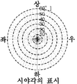
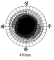
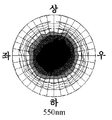
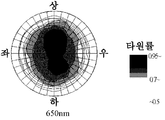
도 15A는 원편광 필름의 시야각 특성 평가의 결과를 도시하는 도면.It is a figure which shows the result of the viewing angle characteristic evaluation of a circularly polarizing film.
도 15B는 원편광 필름의 시야각 특성 평가의 결과를 도시하는 도면.It is a figure which shows the result of the viewing angle characteristic evaluation of a circularly polarizing film.
도 15C는 원편광 필름의 시야각 특성 평가의 결과를 도시하는 도면.15C is a diagram showing results of evaluation of viewing angle characteristics of circularly polarized films.
도 15D는 원편광 필름의 시야각 특성 평가의 결과를 도시하는 도면.It is a figure which shows the result of the viewing angle characteristic evaluation of a circularly polarizing film.
이하, 본 발명의 실시의 형태를, 도면을 참조하면서 설명한다. 또한, 이하에 설명한 실시의 형태는, 본 발명의 한 예이고, 본 발명이 이것으로 한정되는 것이 아니다. 또한, 본 발명은, 이하의 내용을 자유롭게 조합시킨 것을 포함하는 것으로 한다.DESCRIPTION OF THE PREFERRED EMBODIMENTS Hereinafter, embodiments of the present invention will be described with reference to the drawings. In addition, embodiment described below is an example of this invention, and this invention is not limited to this. In addition, this invention shall include what combined the following contents freely.
이하, 본 발명을 적용한 실시의 형태에 관한 계측 장치로서, 시료(100)로부터 출사한 광(분석 대상광)의 편광 상태를 계측하는 계측 장치(1)에 관해 설명한다. 또한, 본 발명에 적용 가능한 시료(100)의 성질은 특히 한정되지 않는다.EMBODIMENT OF THE INVENTION Hereinafter, the measuring
(1) 장치 구성(1) device configuration
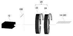
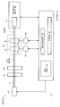
도 1 및 도 2는, 계측 장치(1)의 장치 구성을 설명하기 위한 도면이다. 또한, 도 1은, 본 발명(계측 장치(1))에 적용 가능한 광학계(10)를 모식적으로 도시하는 도면이고, 도 2는, 계측 장치(1)의 구성을 설명하기 위한 블록도이다.1 and 2 are diagrams for explaining the device configuration of the
계측 장치(1)는, 광학계(10)와, 광강도 정보 취득부(30)와, 연산 처리부(50)를 포함한다. 광강도 정보 취득부(30)에서는, 변조부(20)에서 분석 대상광(시료(100)에 의해 변조한 광)을 변조시킴에 의해 얻어지는 변조광의 광강도 정보를 취득한다. 즉, 계측 장치(1)에서는, 광강도 정보 취득부(30)는, 광원(12)으로부터 출사되고, 광학계(10)에 포함되는 광학 소자 및 시료(100)에 의해 변조된 광(변조광)의 광강도 정보를 취득한다. 또한, 계측 장치(1)에서는, 연산 처리부(50)는, 변조광의 광강도의 이론식과, 변조광의 광강도 정보에 의거하여, 시료(100)에 의해 변조한 광(분석 대상광)의 광학 특성 요소를 산출하는 처리를 행하다. 또한, 시료(100)는, 광을 투과시키는 물질이라도 좋고, 광을 반사시키는 물질이라도 좋다.The
이하, 계측 장치(1)의 장치 구성에 관해 설명한다.Hereinafter, the apparatus structure of the measuring
1-1 : 광학계(10)1-1:
광학계(10)는, 광원(12)과 수광부(14)를 포함한다. 광학계(10)는, 또한, 광원(12)과 수광부(14)를 잇는 광로(L)상에 마련된, 리타더(22), 검광자(24)를 포함 한다. 리타더(22) 및 검광자(24)는, 시료(100)로부터 출사된 광(분석 대상광)을 변조시키는 광학 소자이다. 즉, 리타더(22) 및 검광자(24)는, 광로(L)에서의, 시료(100)의 하류측에 배치된다. 리타더(22)와 검광자(24)를 합쳐서, 변조부(20)라고 부를 수 있다. 이하, 광학계(10)의 각 요소에 관해 설명한다.The
광학계(10)는, 광원(12)을 포함한다. 광원(12)은, 광을 발생하고, 출사하는 장치이다. 본 실시의 형태에서는, 광원(12)으로서, 주어진 파장(파수(波數)) 대역 성분을 포함하는 광을 출사하는 장치를 이용하여도 좋다. 예를 들면, 광원(12)으로서, 할로겐 램프 등의 백색 광원을 사용하여도 좋다. 광원(12)은, 또는, 주어진 파장(파수)의 광을 출사하는 광원이라도 좋다. 이 때, 광원(12)은, 단색광을 출사하는 발광 장치라고 할 수 있다. 광원(12)으로서, 레이저나 SLD 등을 이용하여도 좋다. 또한, 광원(12)은, 출사하는 광의 파장(파수)을 변경하는 것이 가능한 구성을 하고 있어도 좋다.The
광학계(10)는, 리타더(22)를 포함한다. 리타더(22)는, 투과한 광의 파장에 따라 그 복굴절 위상차의 크기가 다른 광학 소자이다. 따라서, 리타더(22)를 투과한 광은, 그 파장에 의해 편광 상태가 변화하게 된다. 또한, 계측 장치(1)에서는, 리타더(22)(변조부(20))에 입사하는 광을, 분석 대상광이라고 칭하여도 좋다. 시료(100)와 리타더(22) 사이에 광학 소자를 배치하지 않는 경우에는, 시료(100)로부터 출사한 광을 가리키고, 분석 대상광이라고 칭하여도 좋다. 또한, 본 발명에서는, 리타더(22)로서, 1차(次)의 리타더를 이용한다.The
광학계(10)는, 검광자(24)를 포함한다. 검광자(24)는, 리타더(22)를 투과한 광(리타더(22)로부터 출사한 광)을 직선 편광하는 출사측의 편광자이다. 그리고, 광학계(10)에서는, 검광자(24)를 투과한 광(검광자(24)로부터 출사된 광)이, 수광부(14)에 입사한다.The
본 발명에서는, 리타더(22)와 검광자(24)를 합쳐서, 변조부(20)라고 칭한다. 그리고, 리타더(22) 및 검광자(24)는, 주축 방위가 변경 가능하게 구성되어 이루어진다. 리타더(22) 및 검광자(24)는, 회전시킴에 의해, 주축 방위를 변경할 수 있도록 구성되어 있어도 좋다. 그리고, 계측 장치(1)에서는, 분석 대상광을 변조부(20)에서 변조시킴에 의해 얻어지는 광을, 변조광이라고 칭한다.In the present invention, the
광학계(10)는, 수광부(14)를 포함한다. 수광부(14)는, 분석 대상광을 변조부(20)에서 변조시킴에 의해 얻어지는 광(변조광)을 수광 하도록 구성되어 있어도 좋다. 수광부(14)로서, 예를 들면, CCD를 이용하여도 좋다.The
분석 대상광(시료(100)에 의해 변조된 광)이 주어진 대역 성분을 포함하는 광인 경우, 수광부(14)는, 분광기와, 복수의 수광 소자를 포함하고 있어도 좋다. 분석 대상광이 주어진 대역 성분을 포함하는 광인 경우에는, 수광부(14)에 입사하는 변조광도 대역 성분을 포함하는 광이 된다. 이 때에, 분광기에 의해 변조광을 파장마다 분광하고, 각각의 수광 소자에서 각 파장의 광의 강도를 계측하면, 복수의 파장대에서의 변조광의 광강도를, 동시에 계측할 수 있다.When the light to be analyzed (light modulated by the sample 100) is light including a given band component, the
또한, 분광기란, 주어진 대역 성분을 포함하는 광(예를 들면 백색 광)을, 파장마다 분광하는 광학 장치(광학 소자)이다. 분광기로서, 예를 들면, 프리즘이나 회절 격자를 이용할 수 있다. 또한, 수광 소자는, 입사한 광을 예를 들면 광전 변 환함에 의해, 입사광의 강도를 측정하는 광학 장치(광학 소자)이다.In addition, a spectroscope is an optical device (optical element) which spectrographs light (for example, white light) containing a given band component for every wavelength. As a spectrometer, a prism or a diffraction grating can be used, for example. The light receiving element is an optical device (optical element) that measures the intensity of incident light by photoelectric conversion of incident light.
광학계(10)는, 또한, 광로(L)상에 마련된 편광자(28)를 포함하고 있어도 좋다(도 2 참조). 편광자(28)는, 광로(L)에서의, 시료(100)의 상류측에 배치된다. 즉, 광학계(10)에 의하면, 광원(12)으로부터 출사된 광을, 편광자(28)를 통하여 시료(100)에 입사시키고, 시료(100)에 의해 변조된 광을, 리타더(22) 및 검광자(24)(변조부(20))를 통하여 수광부(14)에 입사시키도록 구성되어 이루어진다. 즉, 광원(12)으로부터 출사된 광을 편광자(28) 및 시료(100)에 의해 변조시킨 광이, 계측 장치(1)에서의 분석 대상광이 된다.The
또한, 본 실시의 형태에 관한 계측 장치(1)는, 변조부(20)(리타더(22))에 입사하는 광(분석 대상광)의 편광 상태를 계측하는 장치이다. 그 때문에, 광로(L)에서의 변조부(20)보다도 상류측의 구성은, 특별히 한정된 것은 아니다. 예를 들면, 계측 장치(1)에서는, 편광자(28)를 포함하지 않는 광학계를 이용하여도 좋다.(도 1 참조).In addition, the measuring
1-2 : 광강도 정보 취득부(30)1-2: light intensity
광강도 정보 취득부(30)는, 변조광의 광강도 정보를 취득한다. 즉, 광강도 정보 취득부(30)는, 변조부(20)에 입사하는 광(분석 대상광)을 변조부(20)에서 변조시킴에 의해 얻어지는 광(변조광)의 광강도 정보를 취득한다. 또한, 광강도 정보 취득부(30)에서 행하여지는, 변조광의 광강도 정보를 취득하는 처리를, 광강도 정보 취득 처리라고 칭하여도 좋다. 광강도 정보 취득부(30)는, 수광부(14)에 입사하는 광의 광강도 정보를 취득하도록 구성되어 있어도 좋다. 또한, 수광부(14)(분광 기 및 수광 소자)는, 광강도 정보 취득부(30)의 일부를 구성하고 있어도 좋다.The light intensity
계측 장치(1)에서는, 광강도 정보 취득부(30)는, 리타더(22)의 주축 방위와 검광자(24)의 주축 방위가 주어진 관계를 충족시키고, 또한, 리타더(22) 및 검광자(24)의 주축 방위의 적어도 한쪽이 다른 제 1 내지 제 N(N은 2 이상의 정수)의 주축 방위 조건으로 설정된 변조부(20)에서 분석 대상광을 변조시킴에 의해 얻어지는, 제 1 내지 제 N의 변조광(복수의 변조광)의 광강도 정보를 취득한다.In the
즉, 광강도 정보 취득부(30)에서는, 제 1 내지 제 N(N은 2 이상의 정수)의 광강도 정보, 즉, N개의 광강도 정보를 취득한다. 여기서, 제 1 내지 제 N의 광강도 정보는, 각각, 제 1 내지 제 N의 주축 방위 조건으로 설정된 변조부(20)에 의해 변조된 변조광의 광강도이다. 그리고, 제 1 내지 제 N의 주축 방위 조건이란, 상호간에, 광학 소자(리타더(22) 및 검광자(24))의 적어도 하나의 주축 방위 설정이 다르다. 또한, 제 1 내지 제 N의 주축 방위 조건에서는, 리타더(22)의 주축 방위와 검광자(24)의 주축 방위는, 소정의 관계를 충족시키고 있다.That is, the light intensity
또한, 리타더(22)의 주축 방위를 θ1으로, 검광자(24)와의 주축 방위를 θ2로 각각 두면, 제 K의 주축 방위 조건은, (θ1,θ2)K=(180×L×K/N, 180×M×K/N)이라도 좋다. 단, L, M은 1 이상의 정수이고, L≠M를 충족시킨다. 또한, L, M은, 짝수라도 좋다. 또한, M은 L의 홀수배(L은 M의 홀수배)라도 좋다. 예를 들면, L=2, M=6, N=30으로 하여도 좋다. θ1 및 θ2를 각각 등간격으로 설정하고, 리타더(22) 및 검광자(24)를 각각 180도 이상(360도 이상)의 대역으로 변화시킴에 의해, 데이 터의 해석 처리(푸리에 해석 처리)에 의한 해석 정밀도를 높일 수 있다.If the main axis orientation of the
단, 본 발명에서는, 변조부(20)는, 반드시 상술한 주축 방위 조건을 충족시키고 있을 필요는 없다. 즉, 본 발명에서는, 이미 공지로 되어 있는 어느 하나의 해석 방법을 적용할 수 있기 때문에, 선택한 해석 방법에 적합한 데이터를 취득하는 것이 가능한, 어느 하나의 주축 방위 조건으로 광강도 정보를 취득하여도 좋다. 또는, 상술한 주축 방위 조건에 초기 위상을 고려하여, 리타더(22)의 주축 방위와 검광자(24)의 주축 방위를 결정하여도 좋다.However, in the present invention, the
그리고, 광강도 정보 취득부(30)에서 취득된 복수의 광강도 정보는, 기억 장치(40)에 격납되어도 좋다. 기억 장치(40)는, 변조부(20)(리타더(22) 및 검광자(24))의 주축 방위 정보(제 1 내지 제 N의 주축 방위 조건)와, 제 1 내지 제 N의 광강도 정보를 대응시켜서 격납하여도 좋다. 그리고, 기억 장치(40)에 격납된 광강도 정보에 의거하여, 연산 처리부(50)가, 분석 대상광의 편광 상태를 계측한 처리를 행한다.The plurality of light intensity information acquired by the light intensity
또한, 계측 장치(1)에서는, 광강도 정보 취득부(30)에서, 리타더(22)의 주축 방위와 검광자(24)의 주축 방위가 주어진 관계를 충족시키고, 또한, 리타더(22) 및 검광자(24)의 적어도 한쪽의 주축 방위가 다른 변조부(20)에서 분석 대상광을 변조시킴에 의해 얻어지는 복수의 변조광의 광강도 정보를 취득한다고 하여도 좋다.In the
즉, 광강도 정보 취득부(30)에서는, 복수의 변조광의 광강도 정보를 취득한다. 그리고, 당해 복수의 변조광이란, 각각, 분석 대상광을, 광학 소자(리타더(22) 및 검광자(24))의 적어도 한쪽의 주축 방위의 설정이 다른 변조부(20)에서 변조시 킴에 의해 얻어지는 광이다. 또한, 복수의 변조광이란, 각각, 분석 대상광을, 리타더(22)의 주축 방위와 검광자(24)의 주축 방위가 주어진 관계를 충족시키는 변조부(20)에서 변조시킴에 의해 얻어지는 광이라고 할 수 있다.That is, the light intensity
1-3 : 연산 처리부(50)1-3: arithmetic processing
연산 처리부(50)는, 분석 대상광의 편광 상태를 계측하는 연산 처리를 행한다. 연산 처리부(50)는, 변조광의 광강도의 이론식과, 변조광의 광강도 정보에 의거하여, 분석 대상광의 편광 특성 요소를 산출하는 처리(편광 특성 요소 산출 처리)를 행하고, 분석 대상광의 편광 상태를 계측한다. 후에 상세히 기술하지만, 변조광의 광강도의 이론식은, 분석 대상광의 편광 상태를 나타내는 파라미터를 포함하고 있다. 그 때문에, 변조광의 광강도의 이론식과, 변조광의 광강도 정보를 이용하면, 분석 대상광의 편광 상태를 나타내는 파라미터(편광 특성 요소)를 산출하는 것이 가능해진다. 그리고, 분석 대상광의 편광 특성 요소를 산출하면, 분석 대상광의 편광 상태를 계측할 수 있다.The
1-4 : 구동·검출부1-4: Drive / detection unit
계측 장치(1)는, 제 1 및 제 2의 구동·검출부(62, 64)를 더 포함하고 있어도 좋다. 구동·검출부 중, 구동부는 광학계를 구성하는 광학 소자의 주축 방위를 가변 설정한 엑추에이터이다. 또한, 검출부는 광학 소자의 주축 방위를 검출하는 센서이다. 계측 장치(1)에서는, 제 1의 구동·검출부(62)는, 리타더(22)를 회전 구동시키고, 리타더(22)의 주축 방위를 검출한다. 또한, 제 2의 구동·검출부(64)는, 검광자(24)를 회전 구동하고, 검광자(24)의 주축 방위를 검출한다.The
그리고, 계측 장치(1)는, 제 1 및 제 2의 구동·검출부(62, 64)의 동작을 제어하는 제어 신호 생성부(65)를 더 포함하고 있어도 좋다. 예를 들면, 제어 신호 생성부(65)는, 제 1 및 제 2의 구동·검출부(62, 64)로부터의 검출 신호에 의거하여 제어 신호를 생성하고, 제 1 및 제 2의 구동·검출부(62, 64)의 동작을 제어하도록 구성되어 있어도 좋다.And the
1-5 : 제어 장치(70)1-5: control device 70
계측 장치(1)는, 제어 장치(70)를 포함하고 있어도 좋다. 제어 장치(70)는, 계측 장치(1)의 동작을 통괄 제어하는 기능을 갖고 있어도 좋다. 즉, 제어 장치(70)는, 제 1 및 제 2의 구동·검출부(62, 64)를 제어하여 광학 소자의 주축 방위를 설정하고, 광원(12)의 발광 동작을 제어하고, 그리고, 광강도 정보 취득부(30) 및 연산 처리부(50)의 동작을 제어하여도 좋다.The measuring
제어 장치(70)는, 기억 장치(40) 및 연산 처리부(50)를 포함하고 있어도 좋다. 또한, 기억 장치(40)는, 여러가지의 데이터를 일시 기억하는 기능을 갖는다. 기억 장치(40)는, 예를 들면, 변조광의 광강도 정보를, 리타더(22) 및 검광자(24)의 주축 방위 정보와 대응시켜서 기억하여도 좋다. 그리고, 연산 처리부(50)는, 기억 장치(40)에 격납된 광강도 정보에 의거하여, 분석 대상광의 편광 특성 요소를 산출하는 처리를 행하여도 좋다. 제어 장치(70)는, 또한, 제어 신호 생성부(65)를 포함하고 있어도 좋다.The control device 70 may include a
또한, 계측 장치(1)는, 특히 제어 장치(70)(연산 처리부(50))에 있어서, 컴퓨터를 이용한 처리가 가능하다. 여기서, 컴퓨터란, 프로세서(처리부 : CPU 등), 메모리(기억부), 입력 장치 및 출력 장치를 기본적인 구성 요소로 한 물리적 장치(시스템)를 말한다.In addition, the
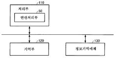
도 3에는, 제어 장치(70)를 구성하는, 연산 처리 시스템의 기능 블록의 한 예를 도시한다.3 shows an example of a functional block of the arithmetic processing system constituting the control device 70.
처리부(110)는, 정보 기억 매체(130)에 격납되는 프로그램(데이터)에 의거하여 본 실시 형태의 여러가지의 처리를 행한다. 즉 정보 기억 매체(130)에는, 본 실시 형태의 각 부분으로서 컴퓨터를 기능시키기 위한 프로그램(각 부분의 처리를 컴퓨터에 실행시키기 위한 프로그램)이 기억된다.The
처리부(110)의 기능은, 각종 프로세서(CPU, DSP 등), ASIC(게이트 어레이 등) 등의 하드웨어나, 프로그램에 의해 실현할 수 있다.The function of the
기억부(120)는, 처리부 등의 워크 영역이 된 것으로, 그 기능은 RAM 등에 의해 실현할 수 있다.The
정보 기억 매체(130)(컴퓨터에 의해 판독 가능한 매체)는, 프로그램이나 데이터 등을 격납하는 것이고, 그 기능은, 광디스크(CD, DVD), 광자기 디스크(MO), 자기 디스크, 하드 디스크, 자기 테이프, 또는 메모리(ROM) 등에 의해 실현할 수 있다. 계측 장치(1)에서는, 정보 기억 매체(130)에 격납된 프로그램에 의거하여, 변조부(20)(리타더(22) 및 검광자(24))의 주축 방위가 설정되고, 광원(12)의 발광 동작이 제어되어도 좋다.The information storage medium 130 (medium that can be read by a computer) stores programs, data, and the like, and its functions are optical discs (CDs and DVDs), magneto-optical discs (MO), magnetic discs, hard discs, and magnetic fields. It can be implemented by a tape or a memory (ROM). In the
(2) 편광 특성 계측 원리(2) measurement principle of polarization characteristics
다음에, 본 실시의 형태에 관한 계측 장치가 채용하는, 편광 상태를 계측하 는 원리(편광 특성 요소를 산출하는 원리)를 설명한다.Next, the principle (the principle of calculating a polarization characteristic element) which measures the polarization state which the measuring apparatus which concerns on this embodiment employ | adopts is demonstrated.
2-1 : 변조광의 광강도의 이론식2-1: Theoretical formula of light intensity of modulated light
리타더(22)의 뮬러 행렬(R)과, 검광자(24)의 뮬러 행렬(A)은,The muller matrix R of the

로 표시할 수 있다.Can be displayed as
또한, δ(λ), θ1, θ2는, 리타더(22)가 갖는 복굴절 위상차, 리타더(22)의 회전각(주축 방위), 검광자(24)의 회전각(주축 방위)이다. 또한, 리타더(22)의 복굴절 위상차는 파장 의존성을 갖기 때문에, 파장(λ)의 함수가 된다. 즉, 식(1)은, 리타더(22)에 파장(λ) 광이 입사한 경우의, 리타더(22)의 복굴절 위상차이다.Note that δ (λ), θ 1 , and θ 2 are the birefringent phase differences of the
시료(100)를 출사 후의 광(분석 대상광)의 편광 상태(Sin)(스톡스 파라미터)를,The polarization state S in (stock parameters) of the light (analysis target light) after exiting the

로 표시하면, 분석 대상광을 변조부(20)에서 변조시킴에 의해 얻어지는 변조광의 편광 상태인 Sout는,When expressed as, S out which is the polarization state of modulated light obtained by modulating the analysis target light in the

로 표시할 수 있다.Can be displayed as
또한, Sin에서의 s0(λ)는 광강도, s1(λ)는 직선 편광 성분, s2(λ)는 45도 편광 성분, s3(λ)는 원편광 성분의 벡터양을 나타낸다. 그리고, Sout에서의 S0(λ)는, 수광부(14)에 입사하는 광(변조광)의 광강도 성분이다. 변조광의 광강도(I)(λ, θ1, θ2)는, 식(4)로부터,In addition, s 0 (λ) in S in is light intensity, s 1 (λ) is linearly polarized light component, s 2 (λ) is 45 degree polarized light component, and s 3 (λ) is vector amount of circularly polarized light component. . S 0 (λ) in S out is a light intensity component of light (modulated light) incident on the

로 표시할 수 있다. 또한, 식(5)에 나타나는 I0(λ)는, 광강도의 비례정수이다.As shown in FIG. In addition, I 0 (λ) shown in equation (5) is a proportional constant of light intensity.
그런데, 광강도(I)(λ, θ1, θ2)의 바이어스 성분 및 cos2θ2, sin2θ2, sin(2θ1-2θ2), cos(4θ1-2θ2), sin(4θ1-2θ2)에서의 진폭 성분은, 식(5)로부터,By the way, the light intensity (I) (λ, θ 1 , θ 2) and a bias component cos2θ 2, sin2θ 2, sin ( 2θ 1 -2θ 2), cos (4θ 1 -2θ 2), sin (4θ 1 -2θ of The amplitude component in 2 ) is obtained from equation (5),

로 표시할 수 있다.Can be displayed as
그래서, 식(6a) 내지 식(6f)를 이용하면, 리타더(22)의 복굴절 위상차 δ(λ)는,Therefore, using the formulas (6a) to (6f), the birefringent phase difference δ (λ) of the

로 표시할 수 있다.Can be displayed as
또한, 후술하는 바와 같이, 식(6a) 내지 식(6f)의 각 좌변은, 광강도 정보로부터 산출 가능하기 때문에, 이들의 값을 식(7)에 대입함으로써, 복굴절 위상차 δ(λ)를 산출할 수 있다.In addition, as will be described later, since the left sides of the formulas (6a) to (6f) can be calculated from the light intensity information, the birefringence phase difference δ (λ) is calculated by substituting these values into the formula (7). can do.
또한, 식(6a) 내지 식(6f)를 이용하면, 분석 대상광의 스톡스 파라미터인 s0(λ), s1(λ), s2(λ), s3(λ)는, 각각,In addition, using Formulas (6a) to (6f), s 0 (λ), s 1 (λ), s 2 (λ), and s 3 (λ) which are Stokes parameters of the analysis target light are respectively,

로 표시할 수 있다.Can be displayed as
(6a) 내지 식(6f)의 각 좌변, 및, 리타더(22)의 복굴절 위상차 δ(λ)가 산 출 가능하기 때문에, 이들의 값을 식(8a) 내지 식(8d)에 대입함으로써, 분석 대상광의 스톡스 파라미터의 각 값도 산출 가능하다.Since each left side of (6a) to (6f) and the birefringent phase difference δ (λ) of the
그리고, 분석 대상광의 타원률 ε(λ)와 주축 방위 φ(λ)는, 스톡스 파라미터를 이용하여,The ellipticity ε (λ) and the main axis orientation φ (λ) of the analysis target light are determined using Stokes parameters.

로 표시할 수 있다.Can be displayed as
이상의 내용으로부터, 본 발명이 채용하는 원리에 의하면, 파장(λ)의 분석 대상광의 편광 특성 요소를 산출할 수 있고, 파장(λ)의 분석 대상광의 편광 특성(편광 상태)을 계측할 수 있는 것을 알 수 있다. 즉, 복굴절 위상차에 파장 의존성이 나타나는 리타더를 이용한 경우에도, 분석 대상광의 전(全)파장에 있어서의 편광 특성 계측을 행하는 것이 가능한 것을 알 수 있다.According to the principle which this invention employ | adopts from the above, it can calculate the polarization characteristic element of the analysis object light of wavelength (lambda), and can measure the polarization characteristic (polarization state) of the analysis object light of wavelength (lambda). Able to know. That is, even when the retarder which shows wavelength dependence in birefringence phase difference is used, it turns out that the polarization characteristic measurement in all wavelengths of the analysis object light can be performed.
2-2 : 실측치의 이용2-2: Use of measured values
식(6a) 내지 식(6f)의 좌변이 나타내는, a0(λ), a2θ2(λ), a4θ1-2θ2(λ), 및, b2θ2(λ), b2θ1-2θ2(λ), b4θ1-2θ2(λ)는, 광강도의 바이어스 성분, cos 성분, 및, sin 성분을 나타내고 있다. 즉, 푸리에 계수이다. 그 때문에, 이들의 계수는,A 0 (λ), a 2θ 2 (λ), a 4θ 1-2θ 2 (λ), and b 2θ 2 (λ), b 2θ 1-2θ 2 (λ), represented by the left side of the formulas (6a) to (6f), b 4θ1-2θ2 (λ) indicates a bias component, a cos component, and a sin component of light intensity. That is, Fourier coefficients. Therefore, these coefficients are

로부터 산출할 수 있다. 즉, 식(6a) 내지 식(6f)의 좌변에 나타나는, a0(λ), a2θ2(λ), a4θ1-2θ2(λ), 및, b2θ2(λ), b2θ1-2θ2(λ), b4θ1-2θ2(λ)는, 광강도 정보(광강도의 실측치)를 이용하여, 수치로서 그 값을 산출할 수 있다.. That is, a 0 (λ), a 2θ 2 (λ), a 4θ 1-2θ 2 (λ), and b 2θ 2 (λ), b 2θ 1-2θ 2 (λ), which appear on the left side of formulas (6a) to (6f), ), b 4θ1-2θ2 (λ) can calculate the value as a numerical value using light intensity information (actual value of light intensity).
그리고, 이들의 값을 이용하면, 식(7), 및 식(8a) 내지 식(8d)로부터, 스톡스 파라미터의 각 값을 산출할 수 있다.And using these values, each value of Stokes parameter can be calculated from Formula (7) and Formula (8a)-Formula (8d).
그리고, 스톡스 파라미터의 각 값을 이용하면, 식(9a) 및 식(9b)로부터, 타원률 및 주축 방위를 수치로서 산출할 수 있다.And if each value of Stokes parameter is used, ellipticity and axle orientation can be computed as numerical value from Formula (9a) and Formula (9b).
2-3 : 리타더(22) 및 검광자(24)가 충족시켜야 할 주축 방위 조건2-3: Spindle bearing condition that the
앞서 설명한 바와 같이, 변조광의 광강도의 이론식은 식(5)로 표시할 수 있는데, 리타더(22)의 주축 방위(θ1)와, 검광자(24)의 주축 방위(θ2)의 설정 여하에 따라서는, 모든 스톡스 파라미터 s0(λ), s1(λ), s2(λ), s3(λ)를 산출할 수 없는 사태가 발생할 수 있다.As described above, the theoretical formula of the light intensity of the modulated light can be expressed by Equation (5), wherein the main axis direction θ 1 of the
예를 들면, 리타더(22)의 주축 방위와 검광자(24)의 주축 방위가 2θ1-2θ2=0의 관계를 충족시키는 변조부에 의해 변조된 광의 광강도의 이론식에서는, 식(5)의 제 4 항은 0이 되어, 얻어진 광강도를 해석 처리하여도 s3(λ)를 측정할 수 없게 된다. 즉, s3(λ)를 측정하기 위해서는, 리타더(22)의 주축 방위와 검광자(24)의 주축 방위는, 2θ1-2θ2≠0이라는 조건을 충족시키고 있을 필요가 있다.For example, in the theoretical formula of the light intensity of light modulated by a modulator in which the main axis orientation of the
마찬가지로 생각하면, 모든 스톡스 파라미터를 산출하기 위해서는, 리타더(22)의 주축 방위와 검광자(24)의 주축 방위가, 2θ1-2θ2≠0, 또한 4θ1-2θ2≠0, 또한 2θ1-2θ2≠4θ1-2θ2≠2θ2를 충족시키고 있을 필요가 있다.Similarly, in order to calculate all Stokes parameters, the main axis direction of the
즉, 리타더(22)의 주축 방위와 검광자(24)의 주축 방위가 상기한 관계를 충족시키고 있는 경우에는, 모든 스톡스 파라미터를 산출할 수 있다. 그 때문에, 효율이 좋은 계측이 가능해진다.That is, when the main axis orientation of the
구체적으로는, 광강도 정보 취득부(30)에서는, 리타더(22)의 주축 방위(θ1)와 검광자(24)의 주축 방위(θ2)가, 3θ1=θ2의 관계를 충족시키는 변조부(20)에 의해 분석 대상광을 변조시키고, 그것에 의해 얻어지는 변조광의 광강도 정보를 취득하여도 좋다. 이에 의하면, 리타더(22)와 검광자(24)가 상기한 조건을 충족시킬 수 있기 때문에, 모든 스톡스 파라미터를 산출하는 것이 가능해진다.Specifically, in the light intensity
예를 들면, 리타더(22)와 검광자(24)를, 회전비가 1 : 3이 되도록 회전시켜 서, 일정한 기간마다 광강도 정보를 취득하여도 좋다. 이로써, 모든 스톡스 파라미터를 산출 가능한 광강도 정보를, 효율 좋게 취득할 수 있다.For example, the
(3) 계측 순서(3) Measurement procedure
다음에, 본 실시의 형태에 관한 계측 장치에 의한 편광 상태의 계측 순서에 관해 설명한다.Next, the measurement procedure of the polarization state by the measurement apparatus which concerns on this embodiment is demonstrated.
도 4 및 도 5는, 본 실시의 형태에 관한 계측 장치의 동작 플로우 차트를 도시한다.4 and 5 show an operation flowchart of the measurement apparatus according to the present embodiment.
3-1 : 광강도 정보 취득 순서3-1: light intensity information acquisition procedure
도 4는, 광강도 정보 취득 순서의 플로우 차트이다.4 is a flowchart of a light intensity information acquisition procedure.
광강도 정보 취득 순서에서는, 우선, 리타더(22) 및 검광자(24)(변조부(20))의 주축 방위를 설정한다(스텝 S10).In the light intensity information acquisition procedure, first, the main axis orientations of the
이 상태에서, 광원(12)으로부터 광을 출사하고, 광학 소자 및 시료(100)에 의해 변조된 광(변조광)을, 수광부(14)에서 수광한다. 그리고, 광강도 정보 취득부(30)에서, 수광부(14)가 수광한 광(변조광)의 광강도 정보를 취득한다(스텝S12).In this state, light is emitted from the
또한, 광강도 정보 취득 순서에서는, 복수의 변조광의 광강도 정보(제 1 내지 제 N의 변조광의 광강도 정보)를 취득한다. 여기서, 제 1 내지 제 N의 변조광은, 제 1 내지 제 N의 주축 방위 조건으로 설정된 변조부(20)에서 분석 대상광을 변조시킴에 의해 얻어지는 측정 광이다. 즉, 광강도 정보 취득 순서에서는, 상기한 스텝 S10 및 스텝 S12를, 광학 소자의 주축 방위 설정을 변경하여 복수회 행한다.In the light intensity information acquisition procedure, light intensity information (light intensity information of first to Nth modulated lights) of the plurality of modulated lights is acquired. Here, the 1st to Nth modulated light is the measurement light obtained by modulating the analysis target light in the
상세하게는, 계측 장치(1)에서는, 처음에, 광학 소자의 주축 방위를 제 1의 조건으로 설정하여, 제 1의 광강도 정보를 취득한다. 그리고, 상술한 기억 장치(40)에, 제 1의 조건(주축 방위 정보)과 제 1의 광강도 정보를 대응시켜서 격납한다. 계속해서, 광학 소자의 주축 방위를 제 2의 조건으로 설정(변경)하여, 제 2의 광강도 정보를 취득하고, 기억 장치(40)에서, 제 2의 조건과 제 2의 광강도 정보를 대응시켜서 격납한다. 이하, 이 동작을 반복하여, N개의 주축 방위 정보와, N개의 광강도 정보를 취득하고, 각각을 대응시켜서, 기억 장치(40)에 격납하여도 좋다.In detail, in the
또한, 광학계의 광학 소자의 주축 방위는, 제어 신호 생성부(65)에 의해, 구동·검출부(62, 64)의 엑추에이터를 동작시켜서 설정(변경)하여도 좋다. 또한, 광학계의 광학 소자의 주축 방위 정보는, 검출부에서 검출하여도 좋고, 미리 프로그램된 정보에 따라도 좋다.In addition, the main axis orientation of the optical element of the optical system may be set (changed) by operating the actuators of the driving / detecting
3-2 : 연산 처리 순서3-2: Operation Processing Sequence
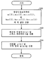
도 5는, 연산 처리 순서의 플로우 차트이다. 연산 처리 순서에서는, 광강도 정보 취득 순서에서 취득된 변조광의 광강도 정보와, 변조광의 이론식에 의거하여, 분석 대상광의 편광 특성 요소를 산출한다.5 is a flowchart of a calculation processing procedure. In the arithmetic processing procedure, the polarization characteristic elements of the analysis target light are calculated based on the light intensity information of the modulated light acquired in the light intensity information acquisition order and the theoretical formula of the modulated light.
연산 처리 순서에서는, 우선 식(10) 내지 식(12)에 의거하여, a0(λ), a2 θ2(λ), a4 θ1-2θ2(λ), 및, b2 θ2(λ), b2 θ1-2θ2(λ), b4 θ1-2θ2(λ)의 각 값을 산출한다(스텝 S20).In the arithmetic processing procedure, first, a 0 (λ), a 2 θ 2 (λ), a 4 θ 1-2 θ 2 (λ), and b 2 θ 2 (λ), based on equations (10) to (12), b 2 θ1-2θ2 (λ), b 4 calculates the respective values of θ1-2θ2 (λ) (step S20).
다음에, 식(7) 및 식(8a) 내지 식(8d)에 의거하여, 리타더(22)의 복굴절 위 상차δ(λ)와, 분석 대상광의 스톡스 파라미터 s0(λ), s1(λ), s2(λ), s3(λ)를 산출한다(스텝 S22).Next, based on equations (7) and (8a) to (8d), the birefringence phase difference δ (λ) of the
그리고, 분석 대상광의 스톡스 파라미터의 각 값을 이용하여, 식(9a) 및 식(9b)에 의거하여, 분석 대상광의 타원률 ε(λ) 및 주축 방위 φ(λ)를 산출한다(스텝 S24).And based on Formula (9a) and Formula (9b), the ellipticity (epsilon) (epsilon) and main-axis orientation (phi) (lambda) of an analysis target light are computed using each value of the Stokes parameter of an analysis target light (step S24). .
이상의 순서에 의해, 분석 대상광의 편광 특성 요소인 타원률과 주축 방위를 산출할 수 있고, 분석 대상광의 편광 상태를 계측할 수 있다.By the above procedure, an ellipticity and a principal axis orientation which are polarization characteristic elements of an analysis object light can be calculated, and the polarization state of an analysis object light can be measured.
(4) 리타더(22)의 복굴절 위상차 δ(λ)에 관해(4) Regarding the birefringence phase difference δ (λ) of the
상술한 바와 같이, 계측 장치(1)에 의하면, 복굴절 위상차가 미지의 리타더를 이용한 경우라도, 식(7)로부터 리타더(22)의 복굴절 위상차 δ(λ)를 산출할 수 있기 때문에, 이것을 이용하여 분석 대상광의 스톡스 파라미터를 산출할 수 있다.As described above, according to the
그런데, 분석 대상광의 스톡스 파라미터가, Sin={s0(λ), s1(λ), s2(λ), s3(λ)}={1, 0, 0, 1}이 되는 경우에는, 식(7)를 이용하여 복굴절 위상차 δ(λ)를 산출할 수 없게 된다. 이 사태를 피하기 위해, 리타더(22)의 복굴절 위상차 δ(λ)를 미리 산출하고, 캘리브레이션 데이터를 취득하고, 이 값을 이용하여 계측을 행하여도 좋다.By the way, when the Stokes parameter of the analysis target light becomes S in = {s 0 (λ), s 1 (λ), s 2 (λ), s 3 (λ)} = {1, 0, 0, 1} The birefringence phase difference δ (λ) cannot be calculated using Equation (7). In order to avoid this situation, the birefringence phase difference δ (λ) of the
구체적으로는, 분석 대상광에 대신하여, 스톡스 파라미터가 {1, 0, 0, 1}이 아닌 샘플광을 변조부(20)에 입사시켜서 광강도 정보 취득 처리를 행하고, 취득된 광강도 정보와, 광강도의 이론식(식(7) 참조)에 의거하여, 복굴절 위상차 δ(λ) 를, 캘리브레이션 데이터로서 산출하는 처리를 행하여도 좋다. 그리고, 본 순서에 의해 산출된 복굴절 위상차 δ(λ)를 기억 장치(40)에 격납하고, 기억 장치(40)에 격납된 복굴절 위상차 δ(λ)를 이용하여, 상술한 편광 특성 요소를 산출하는 처리를 행하여도 좋다.Specifically, in place of the analysis target light, a sample light whose Stokes parameter is not {1, 0, 0, 1} is incident on the
또한, 복굴절 위상차 δ(λ)는, 리타더(22)에 고유의 값이 되기 때문에, 이것은 한번 산출하고, 기억 장치(40)에 격납함으로써, 이후, 복굴절 위상차 δ(λ)를 산출하는 작업을 행할 필요가 없어지고, 연산 효율을 높일 수 있다.In addition, since the birefringent phase difference δ (λ) becomes a value unique to the
(5) 변형예(5) Modifications
이하, 본 발명을 적용한 실시의 형태의 변형예에 관한 계측 장치에 관해 설명한다. 또한, 본 실시의 형태에서도, 이미 설명한 내용을 가능한 한 적용하는 것으로 한다.Hereinafter, the measurement apparatus which concerns on the modification of embodiment to which this invention is applied is demonstrated. In addition, also in this embodiment, the content already demonstrated shall apply as much as possible.
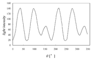
본 실시의 형태에 관한 계측 장치에서는, 광강도 정보 취득부(30)는, 리타더(22) 및 검광자(24)가 주어진 회전비로 회전하는 변조부(20)에서 분석 대상광을 변조시킴에 의해 얻어지는 변조광의 광강도 정보를 취득한다. 이에 의하면, 광강도 정보 취득부(30)는, 도 6에 도시하는 바와 같이, 연속적으로 강도가 변화하는 변조광의 광강도 정보를 아날로그 정보로서 취득할 수 있다.In the measuring device according to the present embodiment, the light intensity
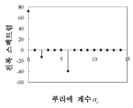
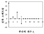
도 6에 도시하는 바와 같이, 광강도는 주기를 갖는 함수라고 파악할 수 있다. 그 때문에, 이것을 해석 처리(예를 들면 푸리에 해석 처리)하면, 도 7에 도시하는 바와 같이, 피크 스펙트럼을 추출할 수 있다. 이들의 피크 스펙트럼을, 광강도의 이론식(상술한 식(6a) 내지 식(6f)의 좌변)에 대응시키면, 식(8a) 내지 식(8d)에 의거하여, 분석 대상광의 스톡스 파라미터를 산출할 수 있다.As shown in FIG. 6, it can be understood that the light intensity is a function having a period. Therefore, if this is an analysis process (for example, a Fourier analysis process), a peak spectrum can be extracted as shown in FIG. If these peak spectra correspond to the theoretical formula of light intensity (the left side of the above-described formulas (6a) to (6f)), the stock parameters of the analysis target light can be calculated based on the formulas (8a) to (8d). Can be.
(6) 검증 결과(6) Verification result
본 발명의 계측 원리 및 그 정밀도를 확인하기 위해 검증 실험을 행하였다. 이하, 그 결과를 나타낸다.Verification experiments were conducted to confirm the measurement principle and precision of the present invention. Hereinafter, the result is shown.
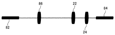
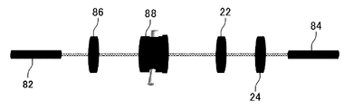
처음에, 633㎚의 헬륨네온 레이저를 이용한 단파장 계측을 행하였다. 본 실험에서는, 도 8에 도시하는 바와 같이, 헬륨네온 레이저의 광원(82)과 파워미터(84)(수광부(14) 및 광강도 정보 취득부(30)) 사이에, 편광자(86)와, 리타더(22) 및 검광자(24)를 배치하였다. 또한, 편광자(86)의 주축 방위는 0도로 설정하였다. 또한, 리타더(22)는, 12도마다 회전시키고, 리타더(22)와 검광자(24)를 1 대 3의 회전비로 회전시켰다. 또한, 리타더(22)로서, 633㎚의 헬륨네온 레이저의 1/4파장판을 이용하였다.First, short wavelength measurement using a 633 nm helium neon laser was performed. In this experiment, as shown in FIG. 8, between the
본 실험에 의하면, 리타더(22)의 복굴절량은 90도, 주축 방위는 -0.15도, 타원률은 0.1% 이였다.According to this experiment, the birefringence of the
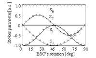
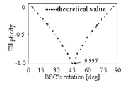
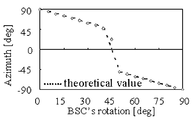
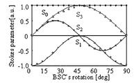
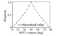
다음에, 도 9에 도시하는 바와 같이, 실제로 시료를 넣어서 타원률의 계측을 행하였다. 또한, 본 실험에서는, 시료로서, 바비넷-솔레일 보상기(88)를 이용하였다. 또한, 바비넷-솔레일 보상기(88)란, 임의로 복굴절 위상차량을 조정할 수 있는 광학 소자(장치)이다. 도 10A 내지 도 10C는, 본 실험에서 계측된 스톡스 파라미터, 타원률 및 주축 방위의 결과를 도시한다. 또한, 본 실험은, 바비넷-솔레일 보상기(88)의 주축 방위를, 0도로부터 90도까지, 5도마다 바꾸어 행하였다. 또한, 도 10A 내지 도 10C의 실선 및 파선은 이론치이고, 플롯 점이 계측 결과이다.Next, as shown in FIG. 9, the sample was actually put in and the ellipticity was measured. In addition, in this experiment, the cabinet-
도 10A 내지 도 10C를 보면, 스톡스 파라미터와 타원률의 결과 모두, 이론치와 동등한 결과가 얻어졌고, 시료의 복굴절량이 90도 부근에서의 계측 정밀도라 하여도, 0.3%로 얻어지는 것을 알 수 있었다. 또한, 주축 방위의 계측 결과에서는, 바비넷-솔레일 보상기(88)의 회전각 45도 부근에서, 이론치와 어긋나 있다. 이 어긋남은, 99.7%의 원편광으로 되어 있기 때문에 일어나고 있는 것이라고 생각된다.10A to 10C show that the results of the Stokes parameters and the ellipticity were the same as the theoretical values, and even when the birefringence of the sample was measured at 90 degrees, it was found that 0.3% was obtained. In addition, in the measurement result of a main-axis orientation, it is shift | deviated from the theoretical value in the vicinity of the
다음에, 위상자의 교체의 필요성에 관해 검증하기 위해, 리타더를 바꾸어서 같은 실험을 행하였다. 본 실험에서는, 리타더(22)로서, 파장 457㎚의 1/4파장판을 이용하였다. 또한, 파장 457㎚의 1/4파장판은, 633㎚의 광에 대해서는, 복굴절량이 약 65도이다. 그 때문에, 리타더의 변조량이 90도 이외인 경우에도 계측하는 것이 가능한지의 여부에 관해 판단할 수 있다. 이 실험 결과를, 도 11A 내지 도 11C에 도시한다.Next, in order to verify the necessity of replacing the retarder, the same experiment was carried out by changing the retarder. In this experiment, a quarter wave plate having a wavelength of 457 nm was used as the
도 11A 내지 도 11C를 보면, 스톡스 파라미터, 타원률 및 주축 방위 모두 이론치와 같은 결과가 얻어졌다. 이것으로부터, 본 발명에 의하면, 리타더(22)의 위상 변조량에 의존한 일 없이 편광 특성을 계측하는 것이 가능한 것을 확인할 수 있다. 또한, 본 실험 결과로부터, 파장 457㎚의 광원을 이용하여, 633㎚의 1/4파장판을 이용한 경우에도, 편광 특성을 계측하는 것이 가능하다는 예측을 세울 수 있다.11A to 11C, the Stokes parameters, the ellipticity, and the major axis orientation all obtained the same results as the theoretical values. From this, according to the present invention, it can be confirmed that the polarization characteristic can be measured without depending on the amount of phase modulation of the
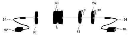
다음에, 다(多)파장 대역의 광을 이용한 실험을 행하였다. 도 12에는, 본 실험에 사용한 실험 장치를 도시한다.Next, experiments using light in multiple wavelength bands were performed. 12 shows the experimental apparatus used for this experiment.
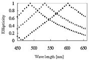
도 12에 도시하는 바와 같이, 광원(92)으로서 할로겐 램프를 이용하고, 광원(92)으로부터의 광을 광파이버(94)에 도출시키고, 콜리메이트 렌즈에 의해 평행 광을 만든다. 계측 시료로는, 단파장 실험과 마찬가지로, 바비넷-솔레일 보상기(88)를 이용하고, 리타더(22)로서 운모판을 이용하였다. 또한, 할로겐 램프는, 400㎚ 내지 800㎚의 파장역까지 퍼지는 백색 광원이다. 할로겐 램프는, 일반적으로, 400㎚ 내지 440㎚와 700㎚ 내지 800㎚의 단(端)파장역에서 광강도가 약하다. 이 때문에, 측정 파장역은, 450㎚ 내지 660㎚로 하였다.As shown in FIG. 12, a halogen lamp is used as the
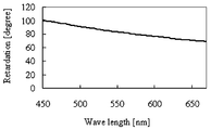
계측에 있어서는, 우선, 리타더(22)의 복굴절 위상차를 구하여, 캘리브레이션 데이터를 취득한다. 캘리브레이션 데이터는, 헬륨네온 레이저에서의 계측과 마찬가지로, 바비넷-솔레일 보상기(88)를 제거한 실험 장치에 의해, 편광자(86)를 투과하여 온 광을 리타더(22)(운모판)에 의해 위상 변조시킨 광강도의 파형을 해석한다. 캘리브레이션으로부터 얻어진 운모판의 복굴절 분산을 도 13에 도시한다.In the measurement, first, the birefringent phase difference of the
다음에, 실제로 측정 시료(바비넷-솔레일 보상기(88))를 넣고, 다파장역에서의 타원률의 계측을 행하였다. 본 실험에서는, 바비넷-솔레일 보상기(88)를 주축 방위 45도로 설치하고, 임의의 파장으로 원편광 상태를 만든다. 바비넷-솔레일 보상기(88)의 복굴절 위상차는 마이크로미터를 보냄에 의해 변화시킴에 의해, 원편광 상태의 파장을 시프트시켰다. 도 14에, 마이크로미터를 변화시켜서, 바비넷-솔레일 보상기의 복굴절 위상차를 변화시킨 결과를 도시한다. 리타더(22)는, 12도마다 회전시켰다. 도면중의 플롯 점은, 파장 5㎚ 걸러서 취하고 있다.Next, the measurement sample (Barnet-soleil compensator 88) was actually put in, and the ellipticity in the multiple wavelength region was measured. In this experiment, the cabinet-
어느 결과에서도, 타원률은 99% 이상의 값이 얻어졌다. 타원률 100%의 결과를 얻기 위해서는, 바비넷-솔레일 보상기의 설치나 검출계의 회전을 더욱 고정밀도로 행함으로써 개선된다고 고찰한다.In either result, an ellipticity of 99% or more was obtained. In order to obtain a result of 100% ellipticity, it is considered that the improvement is achieved by more precisely installing the cabinet-soleil compensator and rotating the detection system.
본 실험 결과로부터, 본 계측 장치에 의하면, 다파장역의 광을 이용한 경우에도, 리타더(22)의 교체가 필요가 없고, 고정밀도인 타원률 계측이 가능한 것을 알 수 있다.From this experiment result, it turns out that even if the light of a multiple wavelength range is used, it is not necessary to replace the
또한, 본 발명은, 상술한 실시의 형태로 한정되는 것이 아니고, 여러가지의 변형이 가능하다. 본 발명은, 실시의 형태에서 설명한 구성과 실질적으로 동일한 구성(예를 들면, 기능, 방법 및 결과가 동일한 구성, 또는 목적 및 효과가 동일한 구성)을 포함한다. 또한, 본 발명은, 실시의 형태에서 설명한 구성의 본질적이 아닌 부분을 치환한 구성을 포함한다. 또한, 본 발명은, 실시의 형태에서 설명한 구성과 동일한 작용 효과를 이루는 구성 또는 동일한 목적을 달성할 수 있는 구성을 포함한다. 또한, 본 발명은, 실시의 형태에서 설명한 구성에 공지(公知) 기술을 부가한 구성을 포함한다.In addition, this invention is not limited to embodiment mentioned above, A various deformation | transformation is possible. This invention includes the structure substantially the same as the structure demonstrated by embodiment (for example, a structure with the same function, method, and result, or a structure with the same objective and effect). In addition, this invention includes the structure which substituted the non-essential part of the structure demonstrated by embodiment. Moreover, this invention includes the structure which achieves the same effect as the structure demonstrated by embodiment, or the structure which can achieve the same objective. Moreover, this invention includes the structure which added a well-known technique to the structure demonstrated by embodiment.
예를 들면, 변조부(20)(리타더(22) 및 검광자(24))는, 수동으로, 그 주축 방위를 변경 가능하게 구성되어 있어도 좋다. 이 경우에는, 검출부에 의해 그 주축 방위 정보를 취득하고, 각종 연산 처리를 행하여도 좋다.For example, the modulator 20 (the
또한, 상기한 실시의 형태에서는, 뮬러 행렬을 이용한 연산 처리에 관해 설명하였다. 단, 본 발명은, 존스 행렬을 이용한 연산 처리를 행하여도 좋다.In addition, in the above embodiment, arithmetic processing using a muller matrix has been described. However, in this invention, you may perform arithmetic processing using a Jones matrix.
또한, 본 발명에 의하면, 분석 대상광의 편광 상태를 계측하고, 명확하게 할 수 있다. 그 때문에, 편광 상태가 미지인 광에 적용하여, 그 편광 상태를 계측할 수 있다. 즉, 측정 시료의 성질에 구애된 일 없이, 편광 상태의 계측이 가능하다. 즉, 광학계(10)(광로(L))에 있어서의 리타더(22) 보다도 상류측의 구성에 구애되는 일 없이, 편광 상태를 계측할 수 있다.Moreover, according to this invention, the polarization state of the analysis object light can be measured and made clear. Therefore, it can apply to the light whose polarization state is unknown, and can measure the polarization state. That is, the polarization state can be measured without being particular about the properties of the measurement sample. In other words, the polarization state can be measured without being limited to the configuration on the upstream side of the
또한, 본 발명에 관한 계측 장치(계측 방법)는, 시료(100)의 광학 특성 요소(복굴절 위상차, 주축 방위, 선광성, 또는, 스톡스 파라미터, 뮬러 행렬 요소, 존스 행렬 요소 등)를 계측하는 계측 장치(계측 방법)로서 구성되어 있어도 좋다. 광원의 성질이나, 광원과 시료(100) 사이에 배치하는 광학 소자를 선택함에 의해, 시료(100)의 광학 특성 요소를 산출하는 것이 가능해진다.Moreover, the measuring apparatus (measurement method) which concerns on this invention is a measuring apparatus which measures the optical characteristic element (birefringence phase difference, axle orientation, opticality, or a Stokes parameter, a Muller matrix element, Jones matrix element, etc.) of the
본 발명은, 액정을 비롯한 유기 고분자 재료의 평가나 신재료의 연구 개발에 이용할 수 있다. 또한, 고분자의 배향 상태를 품질 관리 등에도 응용이 가능하다. 이들로부터 얻어지는 식견은 새로운 재료에 매우 유효한 것이 된다.INDUSTRIAL APPLICABILITY The present invention can be used for evaluation of organic polymer materials including liquid crystals and research and development of new materials. Moreover, the orientation state of a polymer is applicable also to quality control. The knowledge obtained from them becomes very effective for new materials.
또한, 도 15A 내지 도 15D에, 본 발명을 이용하여 원편광 필름의 시야각 특성을 평가한 결과를 도시한다. 여기서, 도 15A는, 시야각 분포의 표시 모델을 나타내고 있다. 그리고, 도 15B 내지 도 15D는, 각각, 측정 대상(시료(100))을 출사한 파장 450㎚, 550㎚, 650㎚의 광(분석 대상광)의 타원률의 계측 결과를 도시하는 도면이다. 또한, 각 도면에서 그레이 레벨은, 타원률의 크기를 나타내고 있다.15A to 15D show the results of evaluating the viewing angle characteristics of the circularly polarized film using the present invention. Here, FIG. 15A has shown the display model of viewing angle distribution. 15B-15D are the figures which show the measurement result of the ellipticity of the light (analysis object light) of wavelength 450nm, 550nm, and 650nm which emitted the measurement object (sample 100), respectively. In addition, in each figure, the gray level has shown the magnitude | size of an ellipticity.
본 발명에 의하면, 측정 대상을 출사한 광(분석 대상광)의 타원률의 시야각 분포를, 도 15B 내지 도 15D에 도시하는 바와 같이 검출할 수 있다.According to the present invention, the viewing angle distribution of the ellipticity of the light (analysis target light) emitted from the measurement object can be detected as shown in Figs. 15B to 15D.
또한, 도 15B 내지 도 15D에 도시하는 결과로부터, 본 실험에 이용한 측정 대상은, 파장에 의해 타원률 시야각 분포가 다른 것을 알 수 있다. 예를 들면, 도 15B를 보면, 파장 450㎚의 상하좌우의 타원률은 거의 균일한 것을 알 수 있다. 이에 대해, 도 15D를 보면, 파장 650㎚에서는 상하 방향의 타원률이 높고, 좌우 방향 의 타원률이 낮게 되어 있는 것을 알 수 있다.In addition, it is understood from the results shown in FIGS. 15B to 15D that the measurement target used in this experiment has different ellipticity viewing angle distributions depending on the wavelength. For example, referring to FIG. 15B, it can be seen that the ellipticity of the top, bottom, left and right with the wavelength of 450 nm is almost uniform. On the other hand, in FIG. 15D, it can be seen that at the wavelength of 650 nm, the ellipticity in the vertical direction is high, and the ellipticity in the left and right directions is low.
즉, 본 발명에 의하면, 도 15B 내지 도 15D에 도시하는 바와 같이, 파장대마다의, 측정 대상의 타원률 분포(분석 대상광의 편광 상태)를, 효율적으로 정확하게 계측할 수 있다.That is, according to this invention, as shown to FIG. 15B-15D, the ellipticity distribution (polarization state of the analysis target light) of a measurement object for every wavelength band can be measured efficiently and correctly.
Claims (17)
Applications Claiming Priority (3)
| Application Number | Priority Date | Filing Date | Title |
|---|---|---|---|
| JP2006054153 | 2006-02-28 | ||
| JPJP-P-2006-00054153 | 2006-02-28 | ||
| PCT/JP2007/052844 WO2007099791A1 (en) | 2006-02-28 | 2007-02-16 | Measuring instrument and measuring method |
Publications (2)
| Publication Number | Publication Date |
|---|---|
| KR20080100452A KR20080100452A (en) | 2008-11-18 |
| KR101267119B1 true KR101267119B1 (en) | 2013-05-23 |
Family
ID=38458904
Family Applications (1)
| Application Number | Title | Priority Date | Filing Date |
|---|---|---|---|
| KR1020087022194A KR101267119B1 (en) | 2006-02-28 | 2008-09-11 | Measuring instrument and measuring method |
Country Status (4)
| Country | Link |
|---|---|
| US (1) | US20090040522A1 (en) |
| JP (1) | JP4677570B2 (en) |
| KR (1) | KR101267119B1 (en) |
| WO (1) | WO2007099791A1 (en) |
Families Citing this family (9)
| Publication number | Priority date | Publication date | Assignee | Title |
|---|---|---|---|---|
| US20100103417A1 (en) * | 2006-03-20 | 2010-04-29 | Yukitoshi Otani | Optical Characteristic Measuring Apparatus, Optical Characteristic Measuring Method, and Optical Characteristic Measuring Unit |
| JP4700667B2 (en) * | 2007-10-01 | 2011-06-15 | 国立大学法人東京農工大学 | Measuring device and measuring method |
| US7837833B2 (en) * | 2007-10-23 | 2010-11-23 | Honeywell Asca Inc. | Method for characterizing fibrous materials using stokes parameters |
| DE102009015393B3 (en) * | 2009-03-20 | 2010-09-02 | Carl Zeiss Smt Ag | Measuring method and measuring system for measuring birefringence |
| US8773662B2 (en) * | 2010-07-22 | 2014-07-08 | Vuv Analytics, Inc. | Methods and apparatus for vacuum ultraviolet (VUV) or shorter wavelength circular dichroism spectroscopy |
| US10168273B1 (en) * | 2017-07-01 | 2019-01-01 | Kla-Tencor Corporation | Methods and apparatus for polarizing reticle inspection |
| KR102095051B1 (en) | 2019-03-18 | 2020-04-24 | 피알씨(주) | Apparatus for injecting sealing hotmelt into cover of medical waste vessel |
| KR102281167B1 (en) * | 2020-02-27 | 2021-07-26 | 전북대학교산학협력단 | Apparatus and method for measuring the retardation of a retarder based on a stokes polarimeter |
| KR102192224B1 (en) | 2020-07-14 | 2020-12-17 | 피알씨(주) | Apparatus for injecting sealing material into the cover of vessel |
Citations (2)
| Publication number | Priority date | Publication date | Assignee | Title |
|---|---|---|---|---|
| JP2005241406A (en) | 2004-02-26 | 2005-09-08 | Nokodai Tlo Kk | Instrument and method for measuring double refraction dispersion |
| JP2005257508A (en) | 2004-03-12 | 2005-09-22 | Nokodai Tlo Kk | Double refraction characteristic measuring device and double refraction characteristic measuring method |
Family Cites Families (9)
| Publication number | Priority date | Publication date | Assignee | Title |
|---|---|---|---|---|
| JPH0612333B2 (en) * | 1988-09-20 | 1994-02-16 | 有限会社ユニオプト | Automatic birefringence measuring device |
| JP2997299B2 (en) * | 1990-06-27 | 2000-01-11 | 旭光学工業株式会社 | Birefringence measurement method |
| JP3456007B2 (en) * | 1994-05-19 | 2003-10-14 | 凸版印刷株式会社 | Optical chopping device |
| EP0737856B1 (en) * | 1995-04-14 | 2010-04-28 | J.A. Woollam Co. Inc. | A method of investigating samples by changing polarisation |
| JP3844222B2 (en) * | 2002-06-14 | 2006-11-08 | ユニオプト株式会社 | Birefringence measuring device |
| JP2005292028A (en) * | 2004-04-02 | 2005-10-20 | Toshiyoshi Kihara | Method of measuring double refraction plate by elliptically polarized light incidence |
| WO2006103953A1 (en) * | 2005-03-28 | 2006-10-05 | National University Corporation Tokyo University Of Agriculture And Technology | Optical characteristics measuring device and optical characteristics measuring method |
| JP4926957B2 (en) * | 2005-06-13 | 2012-05-09 | 国立大学法人宇都宮大学 | Optical characteristic measuring apparatus and optical characteristic measuring method |
| JP4747304B2 (en) * | 2006-01-13 | 2011-08-17 | 国立大学法人東京農工大学 | Measuring device, measuring method, and characteristic measuring unit |
-
2007
- 2007-02-16 WO PCT/JP2007/052844 patent/WO2007099791A1/en active Search and Examination
- 2007-02-16 US US12/224,491 patent/US20090040522A1/en not_active Abandoned
- 2007-02-16 JP JP2008502703A patent/JP4677570B2/en not_active Expired - Fee Related
-
2008
- 2008-09-11 KR KR1020087022194A patent/KR101267119B1/en not_active IP Right Cessation
Patent Citations (2)
| Publication number | Priority date | Publication date | Assignee | Title |
|---|---|---|---|---|
| JP2005241406A (en) | 2004-02-26 | 2005-09-08 | Nokodai Tlo Kk | Instrument and method for measuring double refraction dispersion |
| JP2005257508A (en) | 2004-03-12 | 2005-09-22 | Nokodai Tlo Kk | Double refraction characteristic measuring device and double refraction characteristic measuring method |
Also Published As
| Publication number | Publication date |
|---|---|
| JPWO2007099791A1 (en) | 2009-07-16 |
| US20090040522A1 (en) | 2009-02-12 |
| WO2007099791A1 (en) | 2007-09-07 |
| KR20080100452A (en) | 2008-11-18 |
| JP4677570B2 (en) | 2011-04-27 |
Similar Documents
| Publication | Publication Date | Title |
|---|---|---|
| KR101267119B1 (en) | Measuring instrument and measuring method | |
| KR100765709B1 (en) | Spectroscopic polarimetry | |
| JP4926957B2 (en) | Optical characteristic measuring apparatus and optical characteristic measuring method | |
| JP4779124B2 (en) | Optical characteristic measuring apparatus and optical characteristic measuring method | |
| JP5722094B2 (en) | Circular dichroism measuring apparatus and circular dichroism measuring method | |
| US20100103417A1 (en) | Optical Characteristic Measuring Apparatus, Optical Characteristic Measuring Method, and Optical Characteristic Measuring Unit | |
| WO2006047422A2 (en) | Birefringence measurement of polymeric films and the like | |
| JP4947998B2 (en) | Optical characteristic measuring apparatus and optical characteristic measuring method | |
| JP3844222B2 (en) | Birefringence measuring device | |
| JP4747304B2 (en) | Measuring device, measuring method, and characteristic measuring unit | |
| JP3562768B2 (en) | Circularly polarized dichroism, method for measuring optical rotation and absorption spectrum and dichrograph for measurement | |
| JP4700667B2 (en) | Measuring device and measuring method | |
| JP2000509830A (en) | Rotation compensator-type spectroscopic ellipsometer system with regression calibration with photoarray detector | |
| JP2001141602A (en) | System and method for evaluating double refraction | |
| JP5041508B2 (en) | Optical characteristic measuring apparatus and method | |
| JP5747317B2 (en) | Polarization measuring apparatus and polarization measuring method | |
| JP3797477B2 (en) | Thickness and moisture measuring method and thickness and moisture measuring device | |
| JP2005241406A (en) | Instrument and method for measuring double refraction dispersion | |
| JP5469590B2 (en) | Magneto-optical spectrum spectrometer, magneto-optical spectrum measuring method and program | |
| CN113654996A (en) | Device and method for measuring phase retardation of composite achromatic wave plate | |
| JP4153412B2 (en) | Ellipsometry method using ellipsometer | |
| JP2010139345A (en) | Birefringence measurement apparatus | |
| JP2010271279A (en) | Measuring apparatus and measurement method | |
| JP5482195B2 (en) | Retardation measuring device | |
| Wakayama et al. | Real-time measurement for birefringence dispersion using double retarder |
Legal Events
| Date | Code | Title | Description |
|---|---|---|---|
| A201 | Request for examination | ||
| E701 | Decision to grant or registration of patent right | ||
| GRNT | Written decision to grant | ||
| FPAY | Annual fee payment |
Payment date: 20160405 Year of fee payment: 4 |
|
| FPAY | Annual fee payment |
Payment date: 20170508 Year of fee payment: 5 |
|
| FPAY | Annual fee payment |
Payment date: 20180504 Year of fee payment: 6 |
|
| LAPS | Lapse due to unpaid annual fee |