JP2015114266A - Polarization analyzing apparatus - Google Patents
Polarization analyzing apparatus Download PDFInfo
- Publication number
- JP2015114266A JP2015114266A JP2013258095A JP2013258095A JP2015114266A JP 2015114266 A JP2015114266 A JP 2015114266A JP 2013258095 A JP2013258095 A JP 2013258095A JP 2013258095 A JP2013258095 A JP 2013258095A JP 2015114266 A JP2015114266 A JP 2015114266A
- Authority
- JP
- Japan
- Prior art keywords
- light
- phase modulator
- spatial phase
- analyzer
- sample
- Prior art date
- Legal status (The legal status is an assumption and is not a legal conclusion. Google has not performed a legal analysis and makes no representation as to the accuracy of the status listed.)
- Granted
Links
Images

Classifications
-
- G—PHYSICS
- G01—MEASURING; TESTING
- G01N—INVESTIGATING OR ANALYSING MATERIALS BY DETERMINING THEIR CHEMICAL OR PHYSICAL PROPERTIES
- G01N21/00—Investigating or analysing materials by the use of optical means, i.e. using sub-millimetre waves, infrared, visible or ultraviolet light
- G01N21/17—Systems in which incident light is modified in accordance with the properties of the material investigated
- G01N21/21—Polarisation-affecting properties
- G01N21/211—Ellipsometry
- G01N2021/213—Spectrometric ellipsometry
-
- G—PHYSICS
- G01—MEASURING; TESTING
- G01N—INVESTIGATING OR ANALYSING MATERIALS BY DETERMINING THEIR CHEMICAL OR PHYSICAL PROPERTIES
- G01N2201/00—Features of devices classified in G01N21/00
- G01N2201/06—Illumination; Optics
- G01N2201/067—Electro-optic, magneto-optic, acousto-optic elements
- G01N2201/0675—SLM
Landscapes
- Physics & Mathematics (AREA)
- Health & Medical Sciences (AREA)
- Life Sciences & Earth Sciences (AREA)
- Chemical & Material Sciences (AREA)
- Analytical Chemistry (AREA)
- Biochemistry (AREA)
- General Health & Medical Sciences (AREA)
- General Physics & Mathematics (AREA)
- Immunology (AREA)
- Pathology (AREA)
- Investigating Or Analysing Materials By Optical Means (AREA)
- Spectrometry And Color Measurement (AREA)
Abstract
Description
本発明は、偏光解析装置に関する。 The present invention relates to an ellipsometer.
特許文献1には、回転検光子法によりサンプルの偏光状態を取得する分光エリプソメータが開示されている。 Patent Document 1 discloses a spectroscopic ellipsometer that acquires the polarization state of a sample by a rotating analyzer method.
特許文献2には、光弾性変調器を用いた位相変調法によりストークスパラメーターS2の符号判定を行うストークスメータが開示されている。
しかしながら、特許文献1に開示された分光エリプソメータでは、検光子を機械的に回転させ、それぞれの角度で光を検出する必要があるため、測定に時間を要する。 However, in the spectroscopic ellipsometer disclosed in Patent Document 1, it is necessary to mechanically rotate the analyzer and detect light at each angle.
また、特許文献2に開示されたストークスメータでは、分光測定を行う場合に、測定波長毎に光弾性変調器の印加電圧を変化させ、それぞれの段階で光を検出する必要があるため、測定に時間を要する。
In addition, in the Stokes meter disclosed in
本発明は、上記課題に鑑みてなされたものであって、その目的は、サンプルの偏光特性を迅速に測定することが可能な偏光解析装置を提供することにある。 The present invention has been made in view of the above problems, and an object of the present invention is to provide an ellipsometer capable of quickly measuring the polarization characteristics of a sample.
上記課題を解決するため、本発明の偏光解析装置は、所定の波長領域を有する光を出射する光源と、前記光源から出射された光が透過する偏光子であって、前記偏光子を透過した光がサンプルに照射される、偏光子と、前記サンプルからの光が透過する空間位相変調器であって、複屈折材料からなり、光軸と直交する面内の第1の方向の各位置で位相差が互いに異なる、空間位相変調器と、前記空間位相変調器を透過した光が透過する検光子と、前記検光子を透過した光を受光するイメージ分光器であって、前記光軸と直交する面内の前記第1の方向とは異なる第2の方向に分光する、イメージ分光器と、を備える。 In order to solve the above-described problem, an ellipsometer of the present invention includes a light source that emits light having a predetermined wavelength region, and a polarizer that transmits light emitted from the light source, the light passing through the polarizer. A polarizer, which is irradiated with light, and a spatial phase modulator that transmits light from the sample, the birefringent material, at each position in a first direction in a plane perpendicular to the optical axis A spatial phase modulator having different phase differences, an analyzer that transmits light transmitted through the spatial phase modulator, and an image spectrometer that receives light transmitted through the analyzer, wherein the optical spectrometer is orthogonal to the optical axis. An image spectroscope for performing spectroscopy in a second direction different from the first direction in the plane to be performed.
また、本発明の一態様では、前記空間位相変調器の位相差は、前記第1の方向に沿って連続的に変化してもよい。 In the aspect of the invention, the phase difference of the spatial phase modulator may continuously change along the first direction.
また、本発明の一態様では、前記空間位相変調器の複屈折率差は、前記第1の方向に沿って連続的に変化してもよい。 In the aspect of the invention, the birefringence difference of the spatial phase modulator may continuously change along the first direction.
また、本発明の一態様では、前記サンプルからの光のビーム径を拡大して前記空間位相変調器に照射するビーム拡大器をさらに備えてもよい。 In one embodiment of the present invention, a beam expander that expands a beam diameter of light from the sample and irradiates the spatial phase modulator may be further provided.
また、本発明の一態様では、前記空間位相変調器は、進相軸または遅相軸の方向が互いに異なる、前記第1の方向に隣り合う2つの領域を含んでもよい。 In one embodiment of the present invention, the spatial phase modulator may include two regions adjacent to each other in the first direction, each having a fast axis direction or a slow axis direction different from each other.
また、本発明の一態様では、前記検光子は、前記空間位相変調器の前記2つの領域にそれぞれ対応する、偏光方向が互いに異なる、前記第1の方向に隣り合う2つの領域を含んでもよい。 In the aspect of the invention, the analyzer may include two regions adjacent to each other in the first direction, each having a different polarization direction, corresponding to the two regions of the spatial phase modulator. .
本発明によると、位相差に応じた分光の情報をワンショットで取得することが可能である。 According to the present invention, it is possible to acquire spectral information according to the phase difference in one shot.
本発明の実施形態を、図面を参照しながら説明する。 Embodiments of the present invention will be described with reference to the drawings.
[偏光解析装置の第1の例]
図1は、第1の例に係る偏光解析装置1の概略を示す図である。本第1の例に係る偏光解析装置1は、分光エリプソメータである。
[First example of ellipsometer]
FIG. 1 is a diagram schematically illustrating an ellipsometer 1 according to a first example. The ellipsometer 1 according to the first example is a spectroscopic ellipsometer.
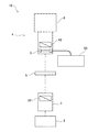
偏光解析装置1は、サンプルSに照射する光を生成する光源2と、光源2で生成された光をサンプルSに照射する投光ユニット3と、サンプルSで反射した光を受光する受光ユニット4と、を備えている。
The ellipsometer 1 includes a
光源2としては、広い波長領域において出力特性が平坦な白色光源が好適であり、重水素ランプやタングステンランプなどを採用してよい。光源2が出射する光は、例えば、少なくとも100nm幅の波長領域を有し、特には、少なくとも200nm幅の波長領域を有することが好ましい。波長領域は、近紫外領域(200〜400nm程度)、可視領域(400〜800nm)及び近赤外領域(800〜1000nm程度)を含む領域内で任意に定められる。例えば、波長領域は、可視領域を全て含んでもよいし、近紫外領域と可視領域に跨がってもよいし、可視領域と近赤外領域に跨がってもよい。
As the
投光ユニット3は、光の入射角度を変えられるように、サンプルSを中心とする円周方向に移動可能に支持されている。投光ユニット3は、偏光子32を備えており、偏光子32を透過する光は、直線偏光に偏光される。
The light projecting unit 3 is supported so as to be movable in the circumferential direction around the sample S so that the incident angle of light can be changed. The light projecting unit 3 includes a
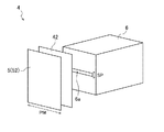
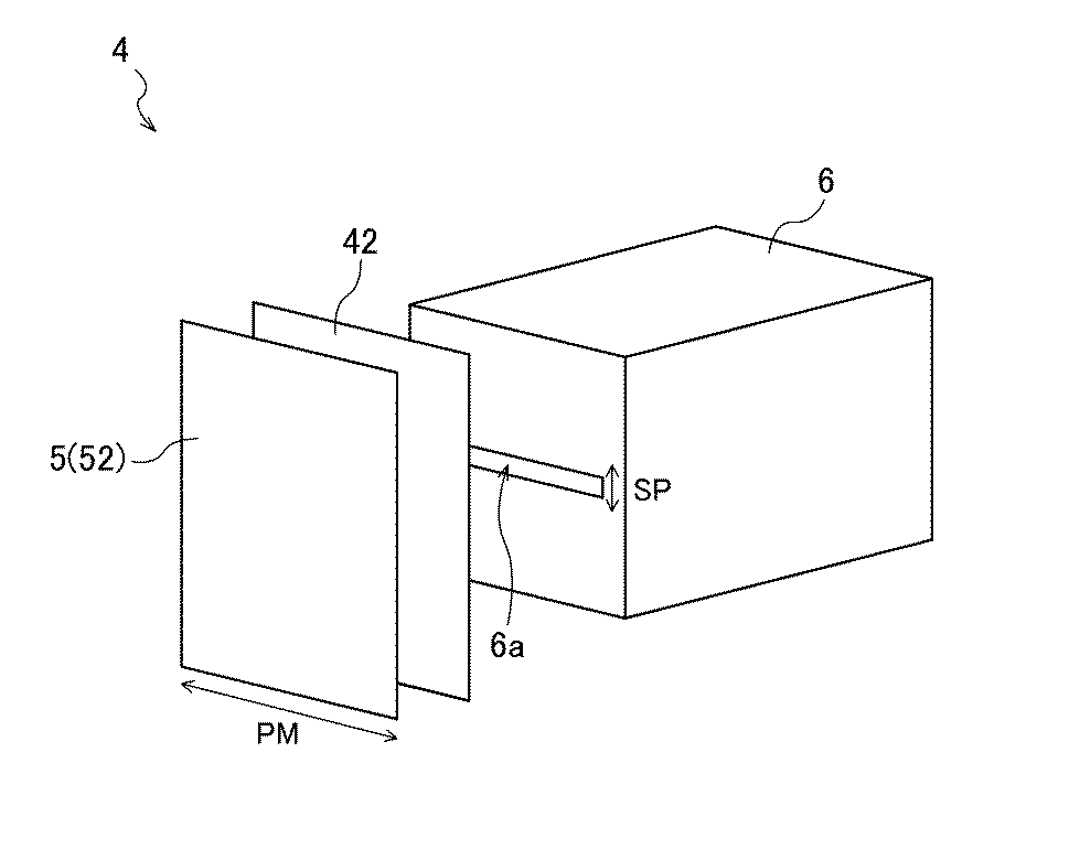
受光ユニット4は、光の検出角度を変えられるように、サンプルSを中心とする円周方向に移動可能に支持されている。受光ユニット4は、空間位相変調器5と、検光子42と、イメージ分光器6と、を備えている。
The
図2は、受光ユニット4の一例の概略を示す図である。受光ユニット4では、空間位相変調器5、検光子42及びイメージ分光器6が、光の上流から下流へこの順番で配列している。
FIG. 2 is a diagram showing an outline of an example of the
空間位相変調器5は、複屈折材料からなり、光軸と直交する面内の位相変調方向PMの各位置で位相差が互いに異なるように構成されている。位相変調方向PMは、イメージ分光器6のスリット6aの長手方向に対応している。空間位相変調器5は、光源2が生成する所定の波長領域を有する光、すなわち白色光を透過させる。空間位相変調器5の進相軸及び遅相軸の方向は、特に限定されない。例えば、進相軸及び遅相軸は、位相変調方向PMと平行及び垂直にそれぞれ設定される。空間位相変調器5の詳細は後述する。
The
空間位相変調器5を透過した光は、検光子42を透過し、その後、イメージ分光器6に到達する。空間位相変調器5の進相軸及び遅相軸の方向と検光子42の偏光方向との角度差は、例えば45度であることが好ましい。偏光子32の偏光方向と検光子42の偏光方向との角度差は、例えば0度であることが好ましい。
The light transmitted through the
イメージ分光器6は、スリット6aから入射する光を分光するグレーティング(回折格子)と、CCD等の撮像素子が2次元に配列したイメージセンサと、を備えている。検光子42を透過した光は、スリット6aによりライン状に成形されて、イメージ分光器6の内部に入射する。グレーティングは、スリット6aから入射する光を、光軸と直交する面内の分光方向SPに分光する。分光方向SPは、スリット6aの幅方向に対応しており、位相変調方向PMと直交している。イメージセンサは、位相変調方向PMの各位置で位相差が互いに異なり、かつ分光方向SPの各位置で波長が互いに異なる光を受光する。これにより、位相差に応じた分光の情報をワンショットで取得することが可能である。
The
不図示の演算装置は、イメージ分光器6が取得した位相差に応じた分光の情報に基づいて、データ解析により波長ごとの位相差Δや振幅比の角度Ψなどを算出し、最終的に膜厚や光学定数などを算出する。
An arithmetic unit (not shown) calculates a phase difference Δ for each wavelength, an angle Ψ of an amplitude ratio, and the like by data analysis based on spectral information corresponding to the phase difference acquired by the
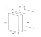
イメージ分光器6は、例えば図3に示されるように、波長可変フィルタ67と、イメージセンサ69と、を備えてもよい。波長可変フィルタ67は、光軸と直交する面内の波長変調方向WMの各位置で波長が互いに異なるように、自身を透過する光の波長を変調させる。波長変調方向WMは、位相変調方向PMと直交している。
For example, as shown in FIG. 3, the
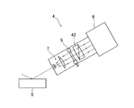
受光ユニット4は、例えば図4に示されるように、ビーム拡大器7をさらに備えてもよい。ビーム拡大器7は、サンプルSで反射した光のビーム径を拡大して空間位相変調器5に照射する。このようなビーム拡大器7を備える態様は、投光ユニット3からサンプルSに照射される光のスポット径が小さい場合に好適である。
For example, as shown in FIG. 4, the
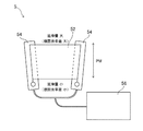
図5は、空間位相変調器5の一例の概略を示す図である。空間位相変調器5は、複屈折材料からなる位相差フィルム52と、位相差フィルム52の両側に取り付けられた一対の延伸器54と、一対の延伸器54に接続されたコントローラ56と、を備えている。
FIG. 5 is a diagram showing an outline of an example of the
一対の延伸器54は、位相差フィルム52の幅方向(図中の上下方向)の一方の側で延伸量が比較的小さく、他方の側で延伸量が比較的大きくなるように、位相差フィルム52を扇状に延伸させる。このとき、位相差フィルム52の複屈折率差は、幅方向の一方の側で比較的小さく、他方の側で比較的大きくなり、幅方向に沿って一方の側から他方の側へ連続的に増加している。これに伴って、位相差フィルム52の位相差も、幅方向に沿って一方の側から他方の側へ連続的に増加している。すなわち、位相差フィルム52の幅方向が、位相変調方向PMとなる。位相差フィルム52は、位相変調方向PMに沿って位相差が0から1波長(360度)まで変化する範囲を含むことが好ましい。
The pair of stretching
コントローラ56は、位相差フィルム52の特性の温度依存性を補償するために、位相差フィルム52の延伸量を調整する。または、コントローラ56は、位相差フィルム52の特性の温度依存性を補償するために、位相差フィルム52の温度を調整してもよい。
The
なお、空間位相変調器5は、上述の態様に限定されない。空間位相変調器5は、上述のように一方向に位相差が変化するような構造の光学部品などであってもよい。
The
[偏光解析装置の第2の例]
図6は、第2の例に係る偏光解析装置10の概略を示す図である。上述の第1の例と重複する構成については、同番号を付すことで詳細な説明を省略する。本第2の例では、投光ユニット3と受光ユニット4とが対向して配置されており、受光ユニット4は、サンプルSを透過した光を受光する。
[Second Example of Ellipsometer]
FIG. 6 is a diagram schematically illustrating the
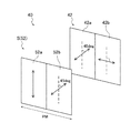
[受光ユニットの変形例]
図7は、変形例に係る受光ユニット40の概略を示す図である。同図では、受光ユニット40に含まれる空間位相変調器5と検光子42のみを示しており、イメージ分光器6の図示を省略している。本変形例は、上述の第1の例にも第2の例にも適用可能である。
[Modification of light receiving unit]
FIG. 7 is a diagram illustrating an outline of a
本変形例では、空間位相変調器5は、位相変調方向PMに隣り合う2つの領域52a,52bを含んでいる。第1の領域52aの進相軸及び遅相軸の方向と、第2の領域52bの進相軸及び遅相軸の方向と、は互いに異なっており、その角度差は例えば45度であることが好ましい。図中の2つの領域52a,52bの内側に示された両矢印は、進相軸の方向を示している。
In this modification, the
同様に、検光子42も、位相変調方向PMに隣り合う2つの領域42a,42bを含んでいる。第1の領域42aの偏光方向と、第2の領域42bの偏光方向と、は互いに異なっており、その角度差は例えば45度であることが好ましい。図中の2つの領域42a,42bの内側に示された両矢印は、偏光方向を示している。
Similarly, the
空間位相変調器5の第1の領域52aと、検光子42の第1の領域42aとは対向しており、空間位相変調器5の第1の領域52aを透過した光は、検光子42の第1の領域42aを透過し、その後、イメージ分光器6に到達する。空間位相変調器5の第1の領域52aの進相軸及び遅相軸の方向と、検光子42の第1の領域42aの偏光方向との角度差は、例えば45度であることが好ましい。
The
空間位相変調器5の第2の領域52bと、検光子42の第2の領域42bとは対向しており、空間位相変調器5の第2の領域52bを透過した光は、検光子42の第2の領域42bを透過し、その後、イメージ分光器6に到達する。空間位相変調器5の第2の領域52bの進相軸及び遅相軸の方向と、検光子42の第2の領域42bの偏光方向との角度差は、例えば45度であることが好ましい。
The
空間位相変調器5の2つの領域52a,52bのそれぞれは、位相変調方向PMに沿って位相差が0から1波長(360度)まで変化する範囲を含むことが好ましい。このような2つの領域52a,52bは、例えば、上述の図5に示される位相差フィルム52、一対の延伸器54及びコントローラ56の組を2つ設けること等によって実現される。
Each of the two
以上に説明した変形例に係る受光ユニット40を用いた場合、ストークスパラメーターS1,S2,S3の全てを算出することが可能である。以下、変形例に係る受光ユニット40を上述の第1の例と第2の例のそれぞれに適用した場合について説明する。
When the
なお、以下の説明において、偏光子32の偏光方向の角度は、空間位相変調器5の第1の領域52aの進相軸(図7を参照)を基準に表される。
In the following description, the angle of the polarization direction of the
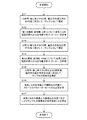
[第1の例への適用]
図8は、変形例に係る受光ユニット40を、第1の例に係る偏光解析装置1(図1を参照)に適用した場合の測定を示すフローチャートである。
[Application to the first example]
FIG. 8 is a flowchart showing measurement when the
S11では、入射角・検出角θを90度、偏光子32の偏光方向を45度に設定して、サンプルSなしで測定する。すなわち、入射角・検出角θを90度にすることで、投光ユニット3と受光ユニット4とを対向させ、両者の間の空気だけを透過した光の強度をイメージ分光器6で測定する。
In S11, the incident angle / detection angle θ is set to 90 degrees and the polarization direction of the
S12では、空間位相変調器5の第1の領域52a(進相軸:0度)について、イメージ分光器6が測定した波長ごとの強度の変化から、後述する数式(2)により位相差分布δ(0〜2π)を計算する。
In S12, for the
S13では、入射角・検出角θを90度、偏光子32の偏光方向を90度に設定して、サンプルSなしで測定する。すなわち、入射角・検出角θを90度にすることで、投光ユニット3と受光ユニット4とを対向させ、両者の間の空気だけを透過した光の強度をイメージ分光器6で測定する。
In S13, the incident angle / detection angle θ is set to 90 degrees and the polarization direction of the
S14では、空間位相変調器5の第2の領域52b(進相軸:45度)について、イメージ分光器6が測定した波長ごとの強度の変化から、後述する数式(2)により位相差分布δ(0〜2π)を計算する。
In S14, for the
S15では、入射角・検出角θを0度以上90度未満、偏光子32の偏光方向を45度に設定して、サンプルSで反射した光の強度をイメージ分光器6で測定する。
In S15, the incident angle / detection angle θ is set to 0 degree or more and less than 90 degrees, the polarization direction of the
S16では、後述する数式(3),(4),(5)により、波長ごとの位相差Δや振幅比の角度Ψ、ストークスパラメーターS1〜S3などを計算する。 In S16, the phase difference Δ for each wavelength, the angle Ψ of the amplitude ratio, the Stokes parameters S1 to S3, and the like are calculated according to equations (3), (4), and (5) described later.
S17では、波長ごとの位相差Δや振幅比の角度Ψなどにより、サンプルSの膜厚及び光学定数などを算出する。 In S17, the film thickness, optical constant, and the like of the sample S are calculated from the phase difference Δ for each wavelength, the angle Ψ of the amplitude ratio, and the like.
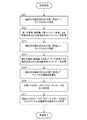
[第2の例への適用]
図9は、変形例に係る受光ユニット40を、第2の例に係る偏光解析装置10(図6を参照)に適用した場合の測定を示すフローチャートである。
[Application to the second example]
FIG. 9 is a flowchart showing the measurement when the
S21では、偏光子32の偏光方向を45度に設定して、サンプルSなしで測定する。すなわち、投光ユニット3と受光ユニット4の間の空気だけを透過した光の強度をイメージ分光器6で測定する。
In S21, the polarization direction of the
S22では、空間位相変調器5の第1の領域52a(進相軸:0度)について、イメージ分光器6が測定した波長ごとの強度の変化から、後述する数式(2)により位相差分布δ(0〜2π)を計算する。
In S22, for the
S23では、偏光子32の偏光方向を90度に設定して、サンプルSなしで測定する。すなわち、投光ユニット3と受光ユニット4の間の空気だけを透過した光の強度をイメージ分光器6で測定する。
In S23, the polarization direction of the
S24では、空間位相変調器5の第2の領域52b(進相軸:45度)について、イメージ分光器6が測定した波長ごとの強度の変化から、後述する数式(2)により位相差分布δ(0〜2π)を計算する。
In S24, for the
S25では、偏光子32の偏光方向を45度に設定して、サンプルSを透過した光の強度をイメージ分光器6で測定する。
In S25, the polarization direction of the
S26では、後述する数式(3),(4),(5)により、波長ごとのストークスパラメーターS1〜S3などを計算する。 In S26, Stokes parameters S1 to S3 and the like for each wavelength are calculated by mathematical formulas (3), (4), and (5) described later.
S27では、波長ごとのストークスパラメーターS1〜S3などにより、サンプルSの複屈折位相差などを計算する。 In S27, the birefringence phase difference of the sample S is calculated from Stokes parameters S1 to S3 for each wavelength.
[ストークスパラメーターの導出]
ストークスパラメーターS1〜S3の導出について、数式を参照しながら説明する。
[Derivation of Stokes parameters]
Derivation of the Stokes parameters S1 to S3 will be described with reference to mathematical expressions.
偏光子32の偏光方向を45度に設定し、空間位相変調器5の進相軸及び遅相軸の方向と検光子42の偏光方向との角度差を45度に設定し、イメージ分光器6で測定したδ=0〜2πの光強度I(δ)は下記数式(1)で与えられる。δは、空間位相変調器5の位相差を表す。
The polarization direction of the
サンプルSなしの場合、上記数式(1)は簡素化されて、下記数式(2)が得られる。 In the case of no sample S, the above formula (1) is simplified and the following formula (2) is obtained.
偏光子32の偏光方向を90度に設定し、空間位相変調器5の進相軸及び遅相軸の方向と検光子42の偏光方向との角度差を45度に設定し、イメージ分光器6で測定したδ=0〜2πの光強度I(δ)も上記数式(1)で与えられ、サンプルSなしの場合には上記数式(2)が得られる。
The polarization direction of the
上記数式(2)から位相差分布を求めて、下記数式(3),(4)で利用する。サンプルSの位相差Δや振幅比の角度Ψは、これら数式(3),(4)から得られる。 The phase difference distribution is obtained from the above equation (2) and used in the following equations (3) and (4). The phase difference Δ of the sample S and the angle Ψ of the amplitude ratio can be obtained from these mathematical formulas (3) and (4).
空間位相変調器5の第1の領域52a(進相軸:0度)に関して、上記数式(1)は下記数式(3)になり、サンプルSの位相差Δや振幅比の角度Ψは、複数のδで測定した光強度を利用して、数式(3)を最小二乗法などで解くことによって得られる。
With respect to the
空間位相変調器5の第2の領域52b(進相軸:45度)に関して、上記数式(1)は下記数式(4)になり、サンプルSの位相差Δや振幅比の角度Ψは、複数のδで測定した光強度を利用して、数式(4)を最小二乗法などで解くことによって得られる。
Regarding the
ストークスパラメーターS1,S2,S3は、サンプルSの位相差Δや振幅比の角度Ψを利用して、下記数式(5)から得られる。 The Stokes parameters S1, S2, and S3 are obtained from the following equation (5) using the phase difference Δ of the sample S and the angle Ψ of the amplitude ratio.
サンプルSの位相差Δや振幅比の角度Ψを得る際に、波長ごとかつ位相ごとに測定した光強度を利用するため、一度に複数の波長の位相差Δや振幅比の角度Ψを得ることができる。これによると、測定精度の向上を図ることが可能である。 When obtaining the phase difference Δ of the sample S and the angle Ψ of the amplitude ratio, the light intensity measured for each wavelength and for each phase is used, so that the phase difference Δ of multiple wavelengths and the angle Ψ of the amplitude ratio are obtained at one time. Can do. According to this, it is possible to improve the measurement accuracy.
従来の回転検光子法や位相変調法では、算出が可能なストークスパラメーターに限りがあるが、以上に説明した方法によれば、ストークスパラメーターS1,S2,S3の全てを算出することが可能である。 In the conventional rotational analyzer method and phase modulation method, the Stokes parameters that can be calculated are limited, but according to the method described above, all of the Stokes parameters S1, S2, and S3 can be calculated. .
以上、本発明の実施形態について説明したが、本発明は上記実施形態に限定されるものではなく、種々の変形実施が当業者にとって可能であるのはもちろんである。 Although the embodiments of the present invention have been described above, the present invention is not limited to the above-described embodiments, and various modifications can be made by those skilled in the art.
1,10 偏光解析装置、2 光源、3 投光ユニット、32 偏光子、4,40 受光ユニット、42 検光子、5 空間位相変調器、52 位相差フィルム、54 延伸器、56 コントローラ、6 イメージ分光器、6a スリット、67 波長可変フィルタ、69 イメージセンサ、7 ビーム拡大器。
DESCRIPTION OF
Claims (6)
前記光源から出射された光が透過する偏光子であって、前記偏光子を透過した光がサンプルに照射される、偏光子と、
前記サンプルからの光が透過する空間位相変調器であって、複屈折材料からなり、光軸と直交する面内の第1の方向の各位置で位相差が互いに異なる、空間位相変調器と、
前記空間位相変調器を透過した光が透過する検光子と、
前記検光子を透過した光を受光するイメージ分光器であって、前記光軸と直交する面内の前記第1の方向とは異なる第2の方向に分光する、イメージ分光器と、
を備える偏光解析装置。 A light source that emits light having a predetermined wavelength region;
A polarizer that transmits light emitted from the light source, and the sample is irradiated with light transmitted through the polarizer; and
A spatial phase modulator that transmits light from the sample, the spatial phase modulator being made of a birefringent material and having different phase differences at each position in a first direction in a plane perpendicular to the optical axis;
An analyzer through which light transmitted through the spatial phase modulator is transmitted;
An image spectrometer for receiving light transmitted through the analyzer, wherein the image spectrometer performs spectroscopy in a second direction different from the first direction in a plane perpendicular to the optical axis;
An ellipsometer comprising:
請求項1に記載の偏光解析装置。 The phase difference of the spatial phase modulator varies continuously along the first direction;
The ellipsometer according to claim 1.
請求項1または2に記載の偏光解析装置。 The birefringence difference of the spatial phase modulator continuously changes along the first direction.
The ellipsometer according to claim 1 or 2.
請求項1ないし3の何れかに記載の偏光解析装置。 A beam expander for expanding the beam diameter of the light from the sample and irradiating the spatial phase modulator;
The ellipsometer according to any one of claims 1 to 3.
請求項1ないし4の何れかに記載の偏光解析装置。 The spatial phase modulator includes two regions adjacent to each other in the first direction, each having a fast axis direction or a slow axis direction different from each other.
The ellipsometer according to any one of claims 1 to 4.
請求項5に記載の偏光解析装置。 The analyzer includes two regions adjacent to each other in the first direction, each having a different polarization direction, corresponding to the two regions of the spatial phase modulator.
The ellipsometer according to claim 5.
Priority Applications (3)
| Application Number | Priority Date | Filing Date | Title |
|---|---|---|---|
| JP2013258095A JP6180311B2 (en) | 2013-12-13 | 2013-12-13 | Ellipsometer |
| KR1020140164291A KR102033522B1 (en) | 2013-12-13 | 2014-11-24 | Polarization analysis device |
| US14/568,122 US9488568B2 (en) | 2013-12-13 | 2014-12-12 | Polarization analysis apparatus |
Applications Claiming Priority (1)
| Application Number | Priority Date | Filing Date | Title |
|---|---|---|---|
| JP2013258095A JP6180311B2 (en) | 2013-12-13 | 2013-12-13 | Ellipsometer |
Publications (2)
| Publication Number | Publication Date |
|---|---|
| JP2015114266A true JP2015114266A (en) | 2015-06-22 |
| JP6180311B2 JP6180311B2 (en) | 2017-08-16 |
Family
ID=53368075
Family Applications (1)
| Application Number | Title | Priority Date | Filing Date |
|---|---|---|---|
| JP2013258095A Active JP6180311B2 (en) | 2013-12-13 | 2013-12-13 | Ellipsometer |
Country Status (3)
| Country | Link |
|---|---|
| US (1) | US9488568B2 (en) |
| JP (1) | JP6180311B2 (en) |
| KR (1) | KR102033522B1 (en) |
Cited By (2)
| Publication number | Priority date | Publication date | Assignee | Title |
|---|---|---|---|---|
| JP2021063828A (en) * | 2016-01-15 | 2021-04-22 | ケーエルエー コーポレイション | Extension infrared spectroscopic ellipsometry system and method |
| WO2025159041A1 (en) * | 2024-01-25 | 2025-07-31 | パナソニックIpマネジメント株式会社 | Interferometric optical system and spectroscopic device |
Families Citing this family (2)
| Publication number | Priority date | Publication date | Assignee | Title |
|---|---|---|---|---|
| US11035790B2 (en) | 2018-12-31 | 2021-06-15 | Industrial Cooperation Foundation Chonbuk National University | Inspection apparatus and inspection method |
| KR102907930B1 (en) * | 2023-05-03 | 2026-01-02 | 서울대학교산학협력단 | Angle-resolved spectroscopic ellipsometer using spatial light modulator and thickness measuring method for thin film |
Citations (9)
| Publication number | Priority date | Publication date | Assignee | Title |
|---|---|---|---|---|
| JPH11337871A (en) * | 1998-05-26 | 1999-12-10 | Seiko Epson Corp | Display device |
| US20030067602A1 (en) * | 2001-05-15 | 2003-04-10 | Patel Jayantilal S. | Polarization analysis unit, calibration method and optimization therefor |
| US20030103214A1 (en) * | 2001-11-02 | 2003-06-05 | Vandelden Jay S. | Interferometric polarization interrogating filter assembly and method |
| US20050007591A1 (en) * | 2003-07-08 | 2005-01-13 | Marine Biological Laboratory | Instantaneous polarization measurement system and method |
| JP2005114704A (en) * | 2003-09-17 | 2005-04-28 | Photonic Lattice Inc | Ellipsometer |
| JP2006308550A (en) * | 2005-03-28 | 2006-11-09 | Omron Corp | Spectral polarization measurement method |
| JP2007040805A (en) * | 2005-08-02 | 2007-02-15 | Hokkaido Univ | Imaging polarization measurement method |
| JP2009103598A (en) * | 2007-10-24 | 2009-05-14 | Dainippon Screen Mfg Co Ltd | Spectroscopic ellipsometer and polarization analysis method |
| JP2010019630A (en) * | 2008-07-09 | 2010-01-28 | Tokyo Institute Of Technology | Microscopic spectroscopic device |
Family Cites Families (5)
| Publication number | Priority date | Publication date | Assignee | Title |
|---|---|---|---|---|
| JP3340145B2 (en) | 1991-12-20 | 2002-11-05 | 日本分光株式会社 | Stork meter |
| US7061613B1 (en) * | 2004-01-13 | 2006-06-13 | Nanometrics Incorporated | Polarizing beam splitter and dual detector calibration of metrology device having a spatial phase modulation |
| JP2005308612A (en) | 2004-04-23 | 2005-11-04 | Photonic Lattice Inc | Ellipsometer and spectroscopic ellipsometer |
| JP5140409B2 (en) | 2007-12-26 | 2013-02-06 | 株式会社フォトニックラティス | Polarimeter, measurement system |
| JP5747317B2 (en) | 2010-11-05 | 2015-07-15 | 国立大学法人宇都宮大学 | Polarization measuring apparatus and polarization measuring method |
-
2013
- 2013-12-13 JP JP2013258095A patent/JP6180311B2/en active Active
-
2014
- 2014-11-24 KR KR1020140164291A patent/KR102033522B1/en active Active
- 2014-12-12 US US14/568,122 patent/US9488568B2/en not_active Expired - Fee Related
Patent Citations (9)
| Publication number | Priority date | Publication date | Assignee | Title |
|---|---|---|---|---|
| JPH11337871A (en) * | 1998-05-26 | 1999-12-10 | Seiko Epson Corp | Display device |
| US20030067602A1 (en) * | 2001-05-15 | 2003-04-10 | Patel Jayantilal S. | Polarization analysis unit, calibration method and optimization therefor |
| US20030103214A1 (en) * | 2001-11-02 | 2003-06-05 | Vandelden Jay S. | Interferometric polarization interrogating filter assembly and method |
| US20050007591A1 (en) * | 2003-07-08 | 2005-01-13 | Marine Biological Laboratory | Instantaneous polarization measurement system and method |
| JP2005114704A (en) * | 2003-09-17 | 2005-04-28 | Photonic Lattice Inc | Ellipsometer |
| JP2006308550A (en) * | 2005-03-28 | 2006-11-09 | Omron Corp | Spectral polarization measurement method |
| JP2007040805A (en) * | 2005-08-02 | 2007-02-15 | Hokkaido Univ | Imaging polarization measurement method |
| JP2009103598A (en) * | 2007-10-24 | 2009-05-14 | Dainippon Screen Mfg Co Ltd | Spectroscopic ellipsometer and polarization analysis method |
| JP2010019630A (en) * | 2008-07-09 | 2010-01-28 | Tokyo Institute Of Technology | Microscopic spectroscopic device |
Cited By (4)
| Publication number | Priority date | Publication date | Assignee | Title |
|---|---|---|---|---|
| JP2021063828A (en) * | 2016-01-15 | 2021-04-22 | ケーエルエー コーポレイション | Extension infrared spectroscopic ellipsometry system and method |
| JP7093429B2 (en) | 2016-01-15 | 2022-06-29 | ケーエルエー コーポレイション | Extended infrared spectroscopic ellipsometry system |
| JP2022121502A (en) * | 2016-01-15 | 2022-08-19 | ケーエルエー コーポレイション | Methods for extended infrared spectroscopic ellipsometry |
| WO2025159041A1 (en) * | 2024-01-25 | 2025-07-31 | パナソニックIpマネジメント株式会社 | Interferometric optical system and spectroscopic device |
Also Published As
| Publication number | Publication date |
|---|---|
| US9488568B2 (en) | 2016-11-08 |
| KR102033522B1 (en) | 2019-10-17 |
| JP6180311B2 (en) | 2017-08-16 |
| KR20150069516A (en) | 2015-06-23 |
| US20150168291A1 (en) | 2015-06-18 |
Similar Documents
| Publication | Publication Date | Title |
|---|---|---|
| JP5722094B2 (en) | Circular dichroism measuring apparatus and circular dichroism measuring method | |
| CN104748854B (en) | Full Stokes interference imaging spectral device and method based on timesharing Polarization Modulation | |
| JP5140451B2 (en) | Birefringence measuring method, apparatus and program | |
| JP6180311B2 (en) | Ellipsometer | |
| JP4677570B2 (en) | Measuring device and measuring method | |
| EP3811056B1 (en) | Apparatus and method for determining presence of a gas in a gas detection volume | |
| EP2610665B1 (en) | Depolarizer and circular dichroism spectrometer using the same | |
| KR101632269B1 (en) | Frequency And Intensity Modulation Laser Absorption Spectroscopy Apparatus and The Measuring Method Of The Same | |
| JP4779124B2 (en) | Optical characteristic measuring apparatus and optical characteristic measuring method | |
| JP5978528B2 (en) | Light irradiation device | |
| WO2006134840A1 (en) | Optical characteristic measuring device and optical characteristic measuring method | |
| JP6239336B2 (en) | Circular dichroism measuring method and circular dichroic measuring device | |
| JP2005257508A (en) | Birefringence characteristic measuring apparatus and birefringence characteristic measuring method | |
| Hu et al. | A liquid crystal variable retarder-based reflectance difference spectrometer for fast, high precision spectroscopic measurements | |
| JP4969631B2 (en) | Birefringence measurement device | |
| JP6239335B2 (en) | Circular dichroism measuring method and circular dichroic measuring device | |
| JP4700667B2 (en) | Measuring device and measuring method | |
| JP2000111472A (en) | Device for measuring birefringence and device for measuring orientation of film | |
| JP2004109032A (en) | Temperature measuring method and temperature measuring device | |
| JP2007286011A (en) | Optical characteristic measuring apparatus and method | |
| JP2013024720A (en) | Refractive index measurement method, refractive index measurement instrument, and refractive index measurement program | |
| Zheng et al. | Determination of the misalignment error of a compound zero-order waveplate using the spectroscopic phase shifting method | |
| EP3760993B1 (en) | Phase difference control device | |
| JP5060388B2 (en) | Online phase difference measuring device | |
| JP2013160651A (en) | Line spectrometric measurement apparatus |
Legal Events
| Date | Code | Title | Description |
|---|---|---|---|
| A621 | Written request for application examination |
Free format text: JAPANESE INTERMEDIATE CODE: A621 Effective date: 20160929 |
|
| A977 | Report on retrieval |
Free format text: JAPANESE INTERMEDIATE CODE: A971007 Effective date: 20170622 |
|
| TRDD | Decision of grant or rejection written | ||
| A01 | Written decision to grant a patent or to grant a registration (utility model) |
Free format text: JAPANESE INTERMEDIATE CODE: A01 Effective date: 20170704 |
|
| A61 | First payment of annual fees (during grant procedure) |
Free format text: JAPANESE INTERMEDIATE CODE: A61 Effective date: 20170718 |
|
| R150 | Certificate of patent or registration of utility model |
Ref document number: 6180311 Country of ref document: JP Free format text: JAPANESE INTERMEDIATE CODE: R150 |
|
| R250 | Receipt of annual fees |
Free format text: JAPANESE INTERMEDIATE CODE: R250 |
|
| R250 | Receipt of annual fees |
Free format text: JAPANESE INTERMEDIATE CODE: R250 |
|
| R250 | Receipt of annual fees |
Free format text: JAPANESE INTERMEDIATE CODE: R250 |
|
| R250 | Receipt of annual fees |
Free format text: JAPANESE INTERMEDIATE CODE: R250 |
|
| R250 | Receipt of annual fees |
Free format text: JAPANESE INTERMEDIATE CODE: R250 |
|
| R250 | Receipt of annual fees |
Free format text: JAPANESE INTERMEDIATE CODE: R250 |