JP2012201573A - Device and method for cutting brittle plate - Google Patents
Device and method for cutting brittle plate Download PDFInfo
- Publication number
- JP2012201573A JP2012201573A JP2011069794A JP2011069794A JP2012201573A JP 2012201573 A JP2012201573 A JP 2012201573A JP 2011069794 A JP2011069794 A JP 2011069794A JP 2011069794 A JP2011069794 A JP 2011069794A JP 2012201573 A JP2012201573 A JP 2012201573A
- Authority
- JP
- Japan
- Prior art keywords
- brittle plate
- glass plate
- brittle
- cutting
- plate
- Prior art date
- Legal status (The legal status is an assumption and is not a legal conclusion. Google has not performed a legal analysis and makes no representation as to the accuracy of the status listed.)
- Withdrawn
Links
Images


Classifications
-
- B—PERFORMING OPERATIONS; TRANSPORTING
- B28—WORKING CEMENT, CLAY, OR STONE
- B28D—WORKING STONE OR STONE-LIKE MATERIALS
- B28D1/00—Working stone or stone-like materials, e.g. brick, concrete or glass, not provided for elsewhere; Machines, devices, tools therefor
- B28D1/22—Working stone or stone-like materials, e.g. brick, concrete or glass, not provided for elsewhere; Machines, devices, tools therefor by cutting, e.g. incising
- B28D1/221—Working stone or stone-like materials, e.g. brick, concrete or glass, not provided for elsewhere; Machines, devices, tools therefor by cutting, e.g. incising by thermic methods
-
- B—PERFORMING OPERATIONS; TRANSPORTING
- B23—MACHINE TOOLS; METAL-WORKING NOT OTHERWISE PROVIDED FOR
- B23K—SOLDERING OR UNSOLDERING; WELDING; CLADDING OR PLATING BY SOLDERING OR WELDING; CUTTING BY APPLYING HEAT LOCALLY, e.g. FLAME CUTTING; WORKING BY LASER BEAM
- B23K26/00—Working by laser beam, e.g. welding, cutting or boring
- B23K26/02—Positioning or observing the workpiece, e.g. with respect to the point of impact; Aligning, aiming or focusing the laser beam
- B23K26/06—Shaping the laser beam, e.g. by masks or multi-focusing
-
- B—PERFORMING OPERATIONS; TRANSPORTING
- B23—MACHINE TOOLS; METAL-WORKING NOT OTHERWISE PROVIDED FOR
- B23K—SOLDERING OR UNSOLDERING; WELDING; CLADDING OR PLATING BY SOLDERING OR WELDING; CUTTING BY APPLYING HEAT LOCALLY, e.g. FLAME CUTTING; WORKING BY LASER BEAM
- B23K26/00—Working by laser beam, e.g. welding, cutting or boring
- B23K26/36—Removing material
- B23K26/40—Removing material taking account of the properties of the material involved
-
- B—PERFORMING OPERATIONS; TRANSPORTING
- B28—WORKING CEMENT, CLAY, OR STONE
- B28D—WORKING STONE OR STONE-LIKE MATERIALS
- B28D1/00—Working stone or stone-like materials, e.g. brick, concrete or glass, not provided for elsewhere; Machines, devices, tools therefor
- B28D1/22—Working stone or stone-like materials, e.g. brick, concrete or glass, not provided for elsewhere; Machines, devices, tools therefor by cutting, e.g. incising
- B28D1/222—Working stone or stone-like materials, e.g. brick, concrete or glass, not provided for elsewhere; Machines, devices, tools therefor by cutting, e.g. incising by pressing, e.g. presses
-
- C—CHEMISTRY; METALLURGY
- C03—GLASS; MINERAL OR SLAG WOOL
- C03B—MANUFACTURE, SHAPING, OR SUPPLEMENTARY PROCESSES
- C03B33/00—Severing cooled glass
- C03B33/02—Cutting or splitting sheet glass or ribbons; Apparatus or machines therefor
- C03B33/023—Cutting or splitting sheet glass or ribbons; Apparatus or machines therefor the sheet or ribbon being in a horizontal position
- C03B33/033—Apparatus for opening score lines in glass sheets
-
- C—CHEMISTRY; METALLURGY
- C03—GLASS; MINERAL OR SLAG WOOL
- C03B—MANUFACTURE, SHAPING, OR SUPPLEMENTARY PROCESSES
- C03B33/00—Severing cooled glass
- C03B33/09—Severing cooled glass by thermal shock
- C03B33/091—Severing cooled glass by thermal shock using at least one focussed radiation beam, e.g. laser beam
-
- B—PERFORMING OPERATIONS; TRANSPORTING
- B23—MACHINE TOOLS; METAL-WORKING NOT OTHERWISE PROVIDED FOR
- B23K—SOLDERING OR UNSOLDERING; WELDING; CLADDING OR PLATING BY SOLDERING OR WELDING; CUTTING BY APPLYING HEAT LOCALLY, e.g. FLAME CUTTING; WORKING BY LASER BEAM
- B23K2103/00—Materials to be soldered, welded or cut
- B23K2103/50—Inorganic material, e.g. metals, not provided for in B23K2103/02 – B23K2103/26
-
- B—PERFORMING OPERATIONS; TRANSPORTING
- B65—CONVEYING; PACKING; STORING; HANDLING THIN OR FILAMENTARY MATERIAL
- B65G—TRANSPORT OR STORAGE DEVICES, e.g. CONVEYORS FOR LOADING OR TIPPING, SHOP CONVEYOR SYSTEMS OR PNEUMATIC TUBE CONVEYORS
- B65G2249/00—Aspects relating to conveying systems for the manufacture of fragile sheets
- B65G2249/04—Arrangements of vacuum systems or suction cups
Abstract
Description
本発明は、脆性板の切断装置および切断方法に関する。 The present invention relates to a brittle plate cutting apparatus and a cutting method.
脆性板であるガラス板の切断装置として、ガラス板の表面にスクライブ線(溝線)を形成するホイールカッターと、スクライブ線に沿ってガラス板を分断するブレイクバーとを有する装置が知られている。スクライブ線は、ホイールカッターをガラス板の表面に押し付けながら転動させることで形成される。 As a cutting device for a glass plate that is a brittle plate, a device having a wheel cutter that forms a scribe line (groove line) on the surface of the glass plate and a break bar that divides the glass plate along the scribe line is known. . The scribe line is formed by rolling while pressing the wheel cutter against the surface of the glass plate.
スクライブ線の形成後、ガラス板に切り込んでいたホイールカッターをガラス板から退出させると、ホイールカッターによって側方に押しやられていた部分が、元の形状に復帰しようとし、相互に衝突するので、水平クラックが発生する。 After the scribe line is formed, if the wheel cutter that had been cut into the glass plate is withdrawn from the glass plate, the parts that were pushed to the side by the wheel cutter will return to their original shape and collide with each other. Cracks occur.
そこで、水平クラックの発生を防止するため、ガラス板を下方に向けて湾曲させた状態で、ガラス板の下面にスクライブ線を形成し、その後、ガラス板をさらに湾曲させることで、ガラス板を分断する技術が提案されている(例えば、特許文献1参照)。この技術によれば、ホイールカッターによって側方に押しやられていた部分が元の形状に復帰するのを低減できるので、水平クラックの発生を低減できるとしている。 Therefore, in order to prevent the occurrence of horizontal cracks, in a state where the glass plate is bent downward, a scribe line is formed on the lower surface of the glass plate, and then the glass plate is further bent to divide the glass plate. The technique which performs is proposed (for example, refer patent document 1). According to this technology, it is possible to reduce the occurrence of horizontal cracks because the portion pushed sideways by the wheel cutter can be reduced from returning to its original shape.
近年では、水平クラックの発生を防止するため、スクライブ線を形成することなく、ガラス板を切断する切断装置も開発されている。例えば、ガラス板を局所的に加熱すると共に加熱領域を移動させることにより、ガラス板を板厚方向に貫通するクラックを形成すると共にクラックを伸展させる手段を有する切断装置がある。 In recent years, in order to prevent the occurrence of horizontal cracks, a cutting apparatus for cutting a glass plate without forming a scribe line has been developed. For example, there is a cutting device that includes means for locally heating a glass plate and moving a heating region to form a crack that penetrates the glass plate in the thickness direction and extend the crack.
ガラス板などの脆性板を板厚方向に貫通するクラックの形成は、脆性板が大面積になるほど、困難である。脆性板が大面積になるほど、脆性板の剛性が高くなるので、また、脆性板と脆性板を支持するステージとの摩擦力が大きくなるので、脆性板が変形し難いためである。この問題は、脆性板の外周部よりも、脆性板の中央部で顕著であり、クラックの伸展が途中で止まることがあった。 Formation of a crack that penetrates a brittle plate such as a glass plate in the thickness direction is more difficult as the brittle plate has a larger area. This is because the larger the brittle plate, the higher the rigidity of the brittle plate, and the greater the frictional force between the brittle plate and the stage that supports the brittle plate, making it difficult for the brittle plate to deform. This problem is more conspicuous in the central portion of the brittle plate than in the outer peripheral portion of the brittle plate, and the extension of the crack may stop midway.
本発明は、上記課題に鑑みてなされたものであって、大面積の脆性板を切断可能な脆性板の切断装置および切断方法を提供することを目的とする。 This invention is made | formed in view of the said subject, Comprising: It aims at providing the cutting apparatus and cutting method of a brittle board which can cut | disconnect a brittle board of a large area.
上記目的を解決するため、本発明は、
脆性板を支持手段により支持する第1のステップと、前記支持手段により支持される脆性板を局所的に加熱すると共に前記脆性板の加熱領域を移動させることにより、前記脆性板を板厚方向に貫通するクラックを形成すると共に該クラックを伸展させる第2のステップとを有する脆性板の切断方法において、
前記第1のステップでは、前記脆性板表面の切断予定線に引張応力が作用するように、前記脆性板の少なくとも一部を曲げ変形させた状態で、前記脆性板を前記支持手段により支持することを特徴とする脆性板の切断方法を提供する。
In order to solve the above object, the present invention provides:
A first step of supporting the brittle plate by the supporting means; and locally heating the brittle plate supported by the supporting means and moving the heating area of the brittle plate to move the brittle plate in the plate thickness direction. In a method for cutting a brittle plate having a second step of forming a crack that penetrates and extending the crack,
In the first step, the brittle plate is supported by the support means in a state where at least a part of the brittle plate is bent and deformed so that a tensile stress acts on a planned cutting line of the brittle plate surface. A method for cutting a brittle plate is provided.
また、本発明は、
脆性板を支持する支持手段と、前記支持手段により支持される脆性板を局所的に加熱すると共に前記脆性板の加熱領域を移動させることより、前記脆性板を板厚方向に貫通するクラックを形成すると共に該クラックを伸展させるクラック形成手段とを有する脆性板の切断装置において、
前記支持手段は、前記脆性板表面の切断予定線に引張応力が作用するように、前記脆性板の少なくとも一部を曲げ変形させた状態で、前記脆性板を支持することを特徴とする脆性板の切断装置を提供する。
The present invention also provides:
Forming a crack penetrating the brittle plate in the thickness direction by locally heating the brittle plate supported by the support means and moving the heating region of the brittle plate while supporting the brittle plate And a brittle plate cutting device having crack forming means for extending the cracks,
The brittle plate is characterized in that the support means supports the brittle plate in a state where at least a part of the brittle plate is bent and deformed so that a tensile stress acts on a planned cutting line on the surface of the brittle plate. A cutting device is provided.
本発明によれば、大面積の脆性板を切断可能な脆性板の切断装置および切断方法を提供することができる。 ADVANTAGE OF THE INVENTION According to this invention, the cutting apparatus and cutting method of a brittle board which can cut | disconnect a brittle board of a large area can be provided.
以下、本発明を実施するための形態について図面を参照して説明するが、各図面において、同一のまたは対応する構成については同一のまたは対応する符号を付して説明を省略する。 DESCRIPTION OF EMBODIMENTS Hereinafter, embodiments for carrying out the present invention will be described with reference to the drawings. In each of the drawings, the same or corresponding components are denoted by the same or corresponding reference numerals, and description thereof will be omitted.
[第1の実施形態]
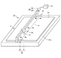
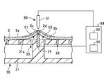
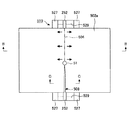
図1は、第1の実施形態における脆性板の切断装置の斜視図である。図2は、第1の実施形態における脆性板の切断装置の断面図である。
[First Embodiment]
FIG. 1 is a perspective view of a brittle plate cutting device according to a first embodiment. FIG. 2 is a cross-sectional view of the brittle plate cutting device in the first embodiment.
本実施形態の切断装置10は、脆性板であるガラス板2を切断する装置である。なお、脆性板は、ガラス板2に限定されず、例えばシリコン基板、サファイア基板、またはセラミックス基板などであってもよい。
The
ガラス板2は、曲げ応力の作用していない自然状態で平板形状に成形されている。ガラス板2の成形方法としては、例えばフロート法やフュージョン法などがある。
The
ガラス板表面2aの切断予定線4の始点または始点近傍には、切断の起点となる初期クラックが予め形成されていてもよいが、工程数を削減するため、初期クラックはなくても良い。
An initial crack serving as a starting point of cutting may be formed in advance at or near the starting point of the planned
ここで、「切断予定線」とは、切断箇所となる予定の仮想線のことである。ガラス板表面2aの切断予定線4の始点および終点は、ガラス板表面2aの外周と交差している。
Here, the “scheduled cutting line” is a virtual line scheduled to be cut. The start point and the end point of the planned
ガラス板2のガラスの種類は、特に限定されないが、例えば、ソーダライムガラス、無アルカリガラス、または石英ガラスなどである。
Although the kind of glass of the
ガラス板2の大きさは、特に限定されないが、例えばガラス板2が矩形状の場合、ガラス板2の短辺の寸法が20mm以上であって良い。
Although the magnitude | size of the
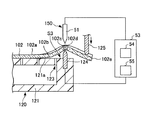
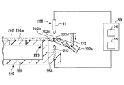
切断装置10は、ガラス板2を支持する支持手段20と、支持手段20により支持されるガラス板2を局所的に加熱すると共にガラス板2の加熱領域を移動させることにより、ガラス板2を板厚方向に貫通するクラック8を形成すると共にクラック8を伸展させるクラック形成手段50を有する。なお、切断装置10は、ガラス板表面2aの損傷を抑えるため、ガラス板表面2aにスクライブ線(溝線)を形成する手段を有していない。
The
支持手段20は、ガラス板表面2aの切断予定線4に引張応力が作用するように、ガラス板2の少なくとも一部を曲げ変形させた状態で、ガラス板2を支持する。上記引張応力の作用方向は、ガラス板表面2aの面内方向で、且つ、切断予定線4と直交する方向であることが好ましい。
The support means 20 supports the
例えば、支持手段20は、図1および図2に示すように、ガラス板2を裏面2bから吸着支持するステージ21と、ステージ21の支持面21aから突出する突起部材24とを有する。突起部材24は、切断予定線4に沿って延びている。
For example, as shown in FIGS. 1 and 2, the
ステージ21の平面形状の支持面21aと直交する方向から見て、突起部材24は、ガラス板2の切断予定線4の全体と重なっている。突起部材24は、自然状態で平板形状のガラス板2を自重で曲げ変形させる。その結果、ガラス板表面2aの切断予定線4に引張応力が作用する。
As seen from the direction orthogonal to the
ステージ21の支持面21aには、複数の吸着孔23が形成されている。各吸着孔23は外部の負圧源Pと接続されている。負圧源Pは真空ポンプなどで構成され、負圧源Pが作動すると、ステージ21が、ガラス板2を裏面2bから吸着支持する。
A plurality of suction holes 23 are formed in the
ステージ21の支持面21aからは、帯板形状の突起部材24が突出しており、突起部材24の左右両側に吸着孔23が配置されている。負圧源Pが作動すると、切断予定線4を挟んだ両側のガラス材が、ステージ21に吸引され、固定される。
From the
ステージ21の支持面21aと、突起部材24と、ガラス板裏面2bとで囲まれる空間S1、S2は、吸着孔23を介して、負圧源Pに接続されている。負圧源Pが作動すると、空間S1、S2に負圧(大気圧よりも低い圧力)が生じ、突起部材24の両側において、ガラス板裏面2bが支持面21aおよび突起部材24に沿うように曲げ変形される。
Spaces S1 and S2 surrounded by the
クラック形成手段50は、支持手段20により支持されるガラス板2を局所的に加熱すると共にガラス板2の加熱領域を移動させることにより、ガラス板2を板厚方向に貫通するクラック8を形成すると共にクラック8を伸展させる手段である。
The crack forming means 50 forms the
クラック形成手段50は、ガラス板2を局所的に加熱することにより、ガラス板2に熱応力を印加して、クラック8を形成する。ガラス板2の加熱温度は、徐冷点以下の温度に設定される。ガラスは徐冷点を超える温度に加熱されると、熱応力を緩和するように、粘性流動するからである。
The
例えば、クラック形成手段50は、図2に示すように、支持手段20により支持されるガラス板2の両側(表面2a側および裏面2b側)に配置される2つの電極51、24を有している。本実施形態では、2つの電極51、24の一方として、帯板形状の突起部材24が用いられている。
For example, as shown in FIG. 2, the
そのため、突起部材24は、導電性を有し、例えばアルミニウムや銅などの金属で構成されている。一方、突起部材24の基端部が埋設されるステージ21は、絶縁性を有しており、例えばポリテトラフルオロエチレン(商品名、テフロン(登録商標))などの合成樹脂で構成されている。
Therefore, the protruding
電極51は、回路53を介して、突起部材24と電気的に接続されている。突起部材24は、アースされていてよい。回路53は、電極51と突起部材24の間に交流電力(交流電圧)を供給する高周波電源54、交流電力(交流電圧)の周波数やデューティ比、電圧を変調する変調器55などで構成される。
The
高周波電源54が電極51と突起部材24の間に交流電力を供給することにより、電極51とガラス板表面2aの間に形成される間隙に放電が生じ、ガラス板表面2aが局所的に加熱される。放電の安定化のため、電極51の周辺の雰囲気は、窒素雰囲気やアルゴン雰囲気などの不活性雰囲気であることが好ましい。
When the high
また、高周波電源54が電極51と突起部材24の間に交流電力を供給することにより、電極51と突起部材24の間に交番電界が形成され、交番電界中に配置されるガラス板2の内部が局所的に誘電加熱される。
Further, when the high
このように、突起部材24と電極51との間に交流電力を供給することにより、突起部材24と電極51の間に配置されるガラス板2を局所的に加熱する。
In this way, by supplying AC power between the projecting
ガラス板2の加熱範囲を狭窄するため、電極51はガラス板表面2aに向けて先細り形状の先端部を有している。同じ理由で、突起部材24は、ガラス板裏面2bに向けて先細り形状の先端部を有している。突起部材24の最大幅Wは、例えば1〜5mmである。
In order to narrow the heating range of the
また、クラック形成手段50は、支持手段20により支持されるガラス板2に対し電極51を相対的に移動させることにより、ガラス板2の加熱領域を移動させる移動装置60を有する。本実施形態の移動装置60は、電極51側を移動させるが、支持手段20側を移動させてもよいし、両側を移動させてもよい。
Further, the
移動装置60は、例えば、電極51を所定方向に案内するガイドレール62、電極51を所定方向に移動させる駆動源64などで構成される。移動装置60は、電極51をガラス板表面2aの切断予定線4に沿って移動させる。
The moving
切断装置10の所定の装置(例えば、負圧源P、高周波電源54、駆動源64)は、切断装置10の動作を制御する制御装置70に、信号ラインを介して接続されている。制御装置70は、CPU、記録媒体などを含むコンピュータとして構成されている。制御装置70は、記録媒体に格納された各種プログラムをCPUに実行させることで、信号ラインを介して接続される装置を制御し、切断装置10の各種動作を実行させる。
Predetermined devices (for example, the negative pressure source P, the high-
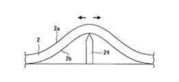
次に、図3A〜図3Cを参照して、上記構成の切断装置10の動作(切断方法)について説明する。
Next, the operation (cutting method) of the cutting
図3Aは、切断装置10による切断の様子を示す上面図である。図3Bは図3AのB−B線に沿った断面図、図3Cは図3AのC−C線に沿った断面図である。図3Aにおいて、図面を見やすくするため、移動装置60などの図示を省略する。
FIG. 3A is a top view showing a state of cutting by the cutting
最初に、ガラス板2が支持手段20により支持される。具体的には、先ず、ガラス板2がステージ21の平面形状の支持面21aに載置される。支持面21aからは突起部材24が突出しているので、自然状態で平板形状のガラス板2が自重で曲げ変形され、ガラス板表面2aの切断予定線4に引張応力が作用する。続いて、負圧源Pが作動し、切断予定線4を挟んだ両側のガラス材が、ステージ21に吸引され、固定される。
First, the
このとき、ステージ21の支持面21aと、突起部材24と、ガラス板裏面2bとで囲まれる空間S1、S2に負圧が生じ、ガラス板裏面2bが支持面21aおよび突起部材24に沿うように曲げ変形される。よって、ガラス板表面2aの切断予定線4により強い引張応力が作用する。
At this time, negative pressure is generated in the spaces S1 and S2 surrounded by the
切断予定線4に作用する引張応力は、突起部材24の突出量H(図3B参照)、空間S1、S2の気圧、ガラス板2の物性などにて定まり、例えば30〜300MPaであり、好ましくは50〜150MPaである。突起部材24の突出量Hは、例えば0.1〜3mmである。
The tensile stress acting on the
次いで、針形状の電極51が切断予定線4の始点と対向する位置に移動される。続いて、電極51と突起部材24との間に交流電力が供給され、電極51と突起部材24との間に配置されるガラス板2が局所的に加熱される。その結果、ガラス板2の外周から、ガラス板2を板厚方向に貫通するクラック8が形成される。
Next, the needle-shaped
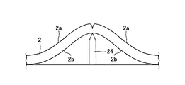
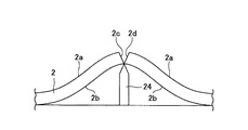
図4A〜図4Cは、クラック8の形成の様子を示す断面図である。図4Aに示すように、ガラス板表面2aの切断予定線4には引張応力が生じているので、図4Bに示すように、クラックはガラス板2の表面2a側から裏面2b側に向けて成長する。図4Cに示すように、クラック8がガラス板2を板厚方向に貫通すると、切断予定線4に作用していた引張応力が解放されるので、ガラス板2の切断面2c、2d同士がV字状に開く。
4A to 4C are cross-sectional views showing how the
次いで、針形状の電極51が切断予定線4に沿って相対的に移動され、クラック8が切断予定線4に沿って伸展する。
Next, the needle-shaped
ところで、ステージ21の支持面21aと、突起部材24と、ガラス板裏面2bとで囲まれる空間S1、S2には負圧が生じているので、ガラス板裏面2bが支持面21aおよび突起部材24に沿うように、ガラス板2に曲げ応力が作用している。
By the way, since negative pressure is generated in the spaces S1 and S2 surrounded by the
この曲げ応力は、突起部材24の左右両側で生じており、クラック8の形成前は、互いに均衡を保っているが、クラック8の形成後は、均衡が崩れる。そのため、クラック8の形成後は、図3Cに示すように、V字状に開いた切断面2c、2d同士が離れる。
This bending stress is generated on both the left and right sides of the projecting
クラック8が切断予定線4の終点に到達すると、交流電力の供給が停止される。また、ステージ21によるガラス板2の吸引が停止され、ステージ21からガラス板2が取り外される。このようにして、ガラス板2を切断することができる。
When the
以上説明したように、本実施形態によれば、ガラス板2の少なくとも一部が曲げ変形されることにより、ガラス板表面2の切断予定線4に曲げ応力が作用しているので、クラック8の形成時に、ガラス板2の切断面2c、2d同士がV字状に開く。そのため、ガラス板2の切断時の変形を支援することができ、大面積のガラス板2を切断することができる。
As described above, according to the present embodiment, the bending stress acts on the
また、本実施形態によれば、図4に示すように、空間S1、S2に負圧が生じることにより、クラック8の形成時に、ガラス板2が再変形し、V字状に開いた切断面2c、2d同士が離れる。よって、切断面2c、2dの角同士が擦れ合うのを防止することができる。
In addition, according to the present embodiment, as shown in FIG. 4, a negative pressure is generated in the spaces S <b> 1 and S <b> 2, so that when the
[第2の実施形態]
上記第1の実施形態では、突起部材24の左右両側に吸着孔23が配置され、突起部材24の左右両側において、ガラス板2がステージ21に吸引され、固定されていた。
[Second Embodiment]
In the first embodiment, the suction holes 23 are disposed on the left and right sides of the protruding
これに対し、本実施形態では、突起部材がステージの支持面の縁部から突出しており、突起部材の片側にのみ吸着孔が配置されている。 On the other hand, in this embodiment, the protruding member protrudes from the edge of the support surface of the stage, and the suction hole is disposed only on one side of the protruding member.
図5Aは、第2の実施形態における切断装置による切断の様子を示す上面図である。図5Bは図5AのB−B線に沿った断面図、図5Cは図5AのC−C線に沿った断面図である。 FIG. 5A is a top view showing a state of cutting by the cutting device in the second embodiment. 5B is a cross-sectional view taken along line BB in FIG. 5A, and FIG. 5C is a cross-sectional view taken along line CC in FIG. 5A.
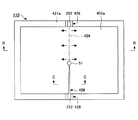
本実施形態の切断装置110は、ガラス板表面102aの切断予定線104に引張応力が作用するように、ガラス板102の少なくとも一部を曲げ変形させた状態で、ガラス板102を支持する支持手段120と、クラック形成手段150を有する。なお、クラック形成手段150は、電極として、図3A〜図3Cに示す突起部材24の代わりに、突起部材124を有する以外は、第1の実施形態と同様の構成であるので、説明を省略する。
The
支持手段120は、ガラス板102を裏面102bから吸着支持するステージ121と、ステージ121の支持面121aの側縁部から突出する突起部材124とを有する。突起部材124は、切断予定線104に沿って延びている。
The support means 120 includes a
ステージ121の平面形状の支持面121aと直交する方向から見て、突起部材124は、切断予定線104の全体と重なっている。突起部材124は、自然状態で平板形状のガラス板102を自重で曲げ変形させる。その結果、ガラス板表面102aの切断予定線104に引張応力が作用する。
As seen from the direction orthogonal to the
ステージ121の支持面121aには、複数の吸着孔123が形成されている。各吸着孔123は外部の負圧源Pと接続されている。負圧源Pが作動すると、ステージ121が、ガラス板102を裏面102bから吸着支持する。
A plurality of suction holes 123 are formed in the
ステージ121の支持面121aの側縁部からは、帯板形状の突起部材124が突出しており、突起部材124の片側のみに吸着孔123が配置されている。負圧源Pが作動すると、切断予定線104を挟んだ両側のガラス材の一方のみが、ステージ121に吸引され、固定される。
A band plate-shaped protruding
ステージ121の支持面121aと、突起部材124と、ガラス板裏面102bとで囲まれる空間S3は、吸着孔123を介して、負圧源Pに接続されている。負圧源Pが作動すると、空間S3に負圧が生じ、ガラス板裏面102bが支持面121aおよび突起部材124に沿うように曲げ変形される。
A space S3 surrounded by the
また、支持手段120は、ガラス板102のステージ121からはみ出す端部102eを表面102a側から裏面102b側に向けて押圧する押圧部材125を有する。よって、ガラス板102の端部102eにある切断予定線104に十分な引張応力を与えることができる。押圧部材125は、切断予定線104と平行に延びている。
The support means 120 includes a
次に、上記構成とした切断装置110の動作(切断方法)について、再度図5A〜図5Cを参照して説明する。
Next, the operation (cutting method) of the
最初に、ガラス板102が支持手段120により支持される。具体的には、先ず、ガラス板102がステージ121の平面形状の支持面121aに載置される。支持面121aからは突起部材124が突出しているので、自然状態で平板形状のガラス板102が自重で曲げ変形され、ガラス板表面102aの切断予定線104に引張応力が作用する。続いて、負圧源Pが作動し、ガラス板102が、ステージ121に吸引され、固定される。
First, the
このとき、ステージ121の支持面121aと、突起部材124と、ガラス板裏面102bとで囲まれる空間S3に負圧が生じ、ガラス板裏面102bが支持面121aおよび突起部材124に沿うように曲げ変形される。よって、ガラス板表面102aの切断予定線104により強い引張応力が作用する。
At this time, negative pressure is generated in the space S3 surrounded by the
また、ガラス板102のステージ121からはみ出す端部102eが、表面102a側から裏面102b側に向けて押圧部材125により押圧されるので、ガラス板表面102aの切断予定線104に十分な引張応力が作用する。
Moreover, since the
切断予定線104に作用する引張応力は、突起部材124の突出量H(図5B参照)、空間S3の気圧、押圧部材125からガラス板102に加わる押圧力、ガラス板102の物性などにて定まり、例えば25〜300MPaであり、好ましくは30〜50MPaである。突起部材124の突出量Hは、例えば0.1〜3mmである。
The tensile stress acting on the
次いで、針形状の電極51が切断予定線104の始点と対向する位置に移動される。続いて、電極51と突起部材124との間に交流電力が供給され、電極51と突起部材124との間に配置されるガラス板102が局所的に加熱される。その結果、ガラス板102の外周から、ガラス板102を板厚方向に貫通するクラック108が形成される。
Next, the needle-shaped
クラック108が形成されると、切断予定線104に作用していた引張応力が解放されるので、ガラス板102の切断面102c、102d同士がV字状に開く。従って、本実施形態でも、第1の実施形態と同様に、ガラス板102の切断時の変形を支援することができ、大面積のガラス板102を切断することができる。
When the
次いで、針形状の電極51が切断予定線104に沿って相対的に移動され、クラック108が切断予定線104に沿って伸展する。
Next, the needle-shaped
ところで、ステージ121の支持面121aと、突起部材124と、ガラス板裏面102bとで囲まれる空間S3には負圧が生じており、ガラス板裏面102bが支持面121aおよび突起部材124に沿うように、ガラス板102に曲げ応力が作用している。
By the way, negative pressure is generated in the space S3 surrounded by the
この曲げ応力は、クラック108の形成前は、押圧部材125の押圧力と均衡を保っているが、クラック108の形成後は、均衡が崩れる。そのため、クラック108の形成後は、図5Cに示すように、V字状に開いた切断面102c、102d同士が離れる。従って、本実施形態でも、第1の実施形態と同様に、切断面102c、102dの角同士が擦れ合うのを防止することができる。
This bending stress is balanced with the pressing force of the
クラック108が切断予定線104の終点に到達すると、交流電力の供給が停止される。また、ステージ121によるガラス板102の吸引が停止され、ステージ121からガラス板102が取り外される。このようにして、ガラス板102を切断することができる。
When the
[第3の実施形態]
上記第1の実施形態の支持手段20は、ステージ21の支持面21aから突出する突起部材24を有していた。
[Third Embodiment]
The support means 20 of the first embodiment has a protruding
これに対し、本実施形態の支持手段は、突起部材を有していない。 On the other hand, the support means of this embodiment does not have a protruding member.
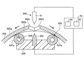
図6Aは、第3の実施形態における切断装置による切断の様子を示す上面図である。図6Bは図6AのB−B線に沿った断面図、図6Cは図6AのC−C線に沿った断面図である。 FIG. 6A is a top view illustrating a state of cutting by the cutting device according to the third embodiment. 6B is a cross-sectional view taken along line BB in FIG. 6A, and FIG. 6C is a cross-sectional view taken along line CC in FIG. 6A.
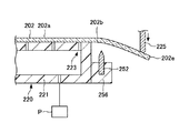
本実施形態の切断装置210は、支持手段220と、クラック形成手段250を有する。
The
支持手段220は、ガラス板表面202aの切断予定線204に引張応力が作用するように、ガラス板202の少なくとも一部を曲げ変形させた状態で、ガラス板202を支持する手段である。
The support means 220 is a means for supporting the
本実施形態の支持手段220は、ガラス板202を裏面202bから吸着支持するステージ221を有する。ステージ221の支持面221aには、複数の吸着孔223が形成されている。各吸着孔223は外部の負圧源Pと接続されている。負圧源Pが作動すると、ステージ221が、ガラス板202を裏面202bから吸着支持する。
The support means 220 of this embodiment has a
また、支持手段220は、ガラス板202のステージ221からはみ出す端部202eを表面202a側から裏面202b側に向けて押圧する押圧部材225を有する。よって、ガラス板202の端部202eを曲げ変形することができ、端部202eにある切断予定線204に引張応力を与えることができる。
Further, the support means 220 includes a
押圧部材225は、ガラス板表面202aの切断予定線204と平行に延びている。
The pressing
クラック形成手段250は、支持手段220により支持されるガラス板202を局所的に加熱すると共にガラス板202の加熱領域を移動させることにより、ガラス板202を板厚方向に貫通するクラック208を形成すると共にクラック208を伸展させる手段である。
The crack forming means 250 forms a
クラック形成手段250は、例えば図6Cに示すように、支持手段220により支持されるガラス板202の両側(表面側および裏面側)に配置される2つの電極51、252を有する。針形状の電極51は、回路53を介して、帯板形状の電極252と電気的に接続されている。
For example, as shown in FIG. 6C, the crack forming means 250 has two
電極252は、切断予定線204に沿って延びている。電極252は、ステージ221の平面形状の支持面221aと直交する方向から見て、切断予定線204の全体と重なっている。
The
電極252は、絶縁性の支持部材256を介して、絶縁性のステージ221に固定されている。電極252は、ガラス板裏面202bとの間に僅かな間隙を形成している。電極252はアースされてよい。
The
高周波電源54が2つの電極51、252の間に交流電力(交流電圧)を供給することにより、電極51とガラス板表面202aの間の間隙に放電が生じ、ガラス板表面202aが局所的に加熱される。また、電極252とガラス板裏面202bの間の間隙に放電が生じ、ガラス板裏面202bが局所的に加熱される。本実施形態では、ガラス板202の表面202a側と裏面202b側の両側に放電が生じるので、加熱効率がよい。
When the high
また、高周波電源54が2つの電極51、252の間に交流電力(交流電圧)を供給することにより、2つの電極51、252の間に交番電界が形成され、交番電界中に配置されるガラス板202の内部が局所的に誘電加熱される。
Further, when the high
このように、2つの電極51、252との間に交流電力を供給することにより、2つの電極51、252の間に配置されるガラス板202を局所的に加熱する。
In this way, by supplying AC power between the two
ガラス板2の加熱範囲を狭窄するため、針形状の電極51はガラス板表面202aに向けて先細り形状の先端部を有している。同じ理由で、帯板形状の電極252は、ガラス板裏面202bに向けて先細り形状の先端部を有している。
In order to narrow the heating range of the
また、クラック形成手段250は、支持手段220により支持されるガラス板2に対し、2つの電極51、252のうち少なくとも一方(本実施形態では、電極51)を相対的に移動させることにより、ガラス板2の加熱領域を移動させる移動装置60を有する。
Further, the crack forming means 250 moves at least one of the two
次に、上記構成とした切断装置210の動作(切断方法)について、再度図6A〜図6Cを参照して説明する。
Next, the operation (cutting method) of the
最初に、ガラス板202が支持手段220により支持される。具体的には、先ず、ガラス板202がステージ221の平面形状の支持面221aに載置される。続いて、支持面221aに形成される吸着孔223に接続される負圧源Pが作動し、ガラス板202が、ステージ221に吸引され、固定される。
First, the
次いで、押圧部材225がガラス板202のステージ221からはみ出す端部202eを表面202a側から裏面202b側に向けて押圧し、端部202eを曲げ変形させる。その結果、端部202eにある切断予定線204に引張応力が作用する。
Next, the pressing
切断予定線204に作用する引張応力は、押圧部材225からガラス板202に加わる押圧力、ガラス板202の物性などにて定まり、例えば25〜300MPaであり、好ましくは30〜50MPaである。
The tensile stress acting on the
次いで、針形状の電極51が切断予定線204の始点と対向する位置に移動される。続いて、2つの電極51、252の間に交流電力が供給され、2つの電極51、252の間に配置されるガラス板202が局所的に加熱される。その結果、ガラス板202の外周から、ガラス板202を板厚方向に貫通するクラック208が形成される。
Next, the needle-shaped
クラック208が形成されると、切断予定線204に作用していた引張応力が解放されるので、ガラス板202の切断面202c、202d同士がV字状に開く。従って、本実施形態でも、第1の実施形態と同様に、ガラス板202の切断時の変形を支援することができ、大面積のガラス板202を切断することができる。
When the
次いで、針形状の電極51が切断予定線204に沿って相対的に移動され、クラック208が切断予定線204に沿って伸展する。
Next, the needle-shaped
ところで、ガラス板202は、元の形状に戻ろうとする復元力を有している。この復元力は、クラック208の形成前は、ステージ221の吸着力や押圧部材225の押圧力と均衡を保っているが、クラック208の形成後は、均衡が崩れる。
By the way, the
そのため、クラック208が形成された切断箇所では、図6Cに示すように、ガラス板202のステージ221により支持される側の部分、および、ガラス板202の押圧部材225により押圧される側の部分が、それぞれ、平板形状に戻る。加えて、ガラス板202の押圧部材225により押圧される側の部分が、押圧方向に移動する。その結果、V字状に開いた切断面202c、202d同士が離される。従って、本実施形態でも、第1の実施形態と同様に、切断面202c、202dの角同士が擦れ合うのを防止することができる。
Therefore, at the cut portion where the
クラック208が切断予定線204の終点に到達すると、交流電力の供給が停止される。また、ステージ221によるガラス板202の吸引が停止され、ステージ221からガラス板202が取り外される。このようにして、ガラス板202を切断することができる。
When the
[第4の実施形態]
上記第1の実施形態では、ガラス板2を裏面2bから吸着支持するステージ21の支持面21aが、平面形状に形成されていた。
[Fourth Embodiment]
In the said 1st Embodiment, the
これに対し、本実施形態では、ガラス板を裏面から支持するステージの支持面が、上に凸の湾曲形状に形成されている。 On the other hand, in this embodiment, the support surface of the stage that supports the glass plate from the back surface is formed in a convex curved shape.
図7Aは、第4の実施形態における切断装置による切断の様子を示す平面図である。図7Bは図7AのB−B線に沿った断面図、図7Cは図7AのC−C線に沿った断面図である。 FIG. 7A is a plan view showing a state of cutting by the cutting device according to the fourth embodiment. 7B is a cross-sectional view taken along line BB in FIG. 7A, and FIG. 7C is a cross-sectional view taken along line CC in FIG. 7A.
切断装置310は、支持手段320と、クラック形成手段250を有する。なお、クラック形成手段250の構成は、第3の実施形態と同様であるので、説明を省略する。
The
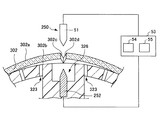
支持手段320は、ガラス板表面302aの切断予定線304に引張応力が作用するように、ガラス板302の少なくとも一部を曲げ変形させた状態で、ガラス板302を支持する手段である。
The support means 320 is a means for supporting the
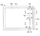
本実施形態の支持手段320は、ガラス板302を裏面302bから吸着支持するステージ321を有する。ステージ321の支持面321aは、上に凸の湾曲形状に形成されている。
The support means 320 of the present embodiment includes a
支持面321aには、複数の吸着孔323が形成されている。各吸着孔323は外部の負圧源Pと接続されている。負圧源Pが作動すると、ステージ321が、ガラス板302を裏面302bから吸着支持する。
A plurality of suction holes 323 are formed in the
支持面321aの上端部には、溝部326が設けられており、溝部326の左右両側に吸着孔323が配置されている。負圧源Pが作動すると、切断予定線304を挟んだ両側のガラス材が、ステージ321に吸引され、固定される。
A
溝部326の内底面からは、帯板形状の電極252が上方に向けて突出している。電極252は、切断予定線304に沿って延びている。電極252は、上面視にて、切断予定線304の全体と重なっている。
A strip-shaped
電極252は、絶縁性のステージ321に一部が埋設され、固定されている。電極252は、ガラス板裏面302bとの間に僅かな間隙を形成している。電極252はアースされてよい。
The
次に、上記構成とした切断装置310の動作(切断方法)について、再度図6A〜図6Cを参照して説明する。
Next, the operation (cutting method) of the
最初に、ガラス板302が支持手段320により支持される。具体的には、先ず、ガラス板302がステージ321の支持面321aに載置される。支持面321aは上に凸の湾曲形状に形成されているので、自然状態で平板形状のガラス板302が自重で曲げ変形して、ガラス板表面302aの切断予定線304に引張応力が作用する。
First, the
続いて、負圧源Pが作動し、切断予定線304を挟んだ両側のガラス材が、ステージ321に吸引され、固定される。負圧源Pの作動前に、ガラス板裏面302bの曲率半径が支持面321aの曲率半径よりも大きい場合、負圧源Pの作動によって、ガラス板302がさらに曲げ変形される。よって、切断予定線304に作用する引張応力が強くなる。
Subsequently, the negative pressure source P is activated, and the glass materials on both sides sandwiching the
切断予定線304に作用する引張応力は、支持面321aの湾曲形状、ガラス板302の物性などにて定まり、例えば25〜300MPaであり、好ましくは30〜50MPaである。
The tensile stress acting on the
次いで、針形状の電極51が切断予定線304の始点と対向する位置に移動される。続いて、2つの電極51、252の間に交流電力が供給され、2つの電極51、252の間に配置されるガラス板302が局所的に加熱される。その結果、ガラス板302の外周から、ガラス板302を板厚方向に貫通するクラック308が形成される。
Next, the needle-shaped
クラック308が形成されると、切断予定線304に作用していた引張応力が解放されるので、ガラス板302の切断面302c、302d同士がV字状に開く。従って、本実施形態でも、第1の実施形態と同様に、ガラス板302の切断時の変形を支援することができ、大面積のガラス板302を切断することができる。
When the
次いで、針形状の電極51が切断予定線304に沿って相対的に移動され、クラック308が切断予定線304に沿って伸展する。
Next, the needle-shaped
ところで、ガラス板302は、元の形状に戻ろうとする復元力を有している。この復元力は、クラック308の形成前は、ガラス板302の左右両側に作用する重力と均衡を保っているが、クラック308の形成後は、均衡が崩れる。
By the way, the
そのため、クラック308が形成された切断箇所では、図7Cに示すように、切断箇所の左側のガラス、および、切断箇所の右側のガラスが、それぞれ、平板形状に戻る。その結果、V字状に開いた切断面302c、302d同士が離される。従って、本実施形態でも、第1の実施形態と同様に、切断面302c、302dの角同士が擦れ合うのを防止することができる。
Therefore, at the cut location where the
クラック308が切断予定線304の終点に到達すると、交流電力の供給が停止される。また、ステージ321によるガラス板302の吸引が停止され、ステージ321からガラス板302が取り外される。このようにして、ガラス板302を切断することができる。
When the
[第5の実施形態]
上記第4の実施形態では、ステージ321の支持面321aの上端部に形成される溝部の両側に吸着孔323が配置されていた。
[Fifth Embodiment]
In the fourth embodiment, the suction holes 323 are arranged on both sides of the groove formed on the upper end of the
これに対し、本実施形態では、溝部の片側にのみ吸着孔が配置されている。 On the other hand, in this embodiment, the suction hole is disposed only on one side of the groove portion.
図8Aは、第5の実施形態における切断装置による切断の様子を示す上面図である。図8Bは図8AのB−B線に沿った断面図、図8Cは図8AのC−C線に沿った断面図である。 FIG. 8A is a top view showing a state of cutting by the cutting device in the fifth embodiment. 8B is a cross-sectional view taken along line BB in FIG. 8A, and FIG. 8C is a cross-sectional view taken along line CC in FIG. 8A.
切断装置410は、支持手段420と、クラック形成手段250を有する。なお、クラック形成手段250の構成は、第3の実施形態と同様であるので、説明を省略する。
The
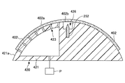
支持手段420は、ガラス板表面402aの切断予定線404に引張応力が作用するように、ガラス板402の少なくとも一部を曲げ変形させた状態で、ガラス板402を支持する手段である。
The support means 420 is a means for supporting the
本実施形態の支持手段420は、ガラス板402を裏面402bから吸着支持するステージ421を有する。ステージ421の支持面421aは、上に凸の湾曲形状に形成されている。
The support means 420 of this embodiment has a stage 421 that sucks and supports the
支持面421aには、複数の吸着孔423が形成されている。各吸着孔423は外部の負圧源Pと接続されている。負圧源Pが作動すると、ステージ421が、ガラス板402を裏面402bから吸着支持する。
A plurality of suction holes 423 are formed in the
支持面421aの上端部には、溝部426が設けられており、溝部426の片側のみに吸着孔423が配置されている。負圧源Pが作動すると、切断予定線404を挟んだ両側のガラス材の一方のみが、ステージ421に吸引され、固定される。
A
溝部426の内底面からは、帯板形状の電極252が上方に向けて突出している。電極252は、切断予定線404に沿って延びている。電極252は、上面視にて、切断予定線404の全体と重なっている。
A strip-shaped
電極252は、絶縁性のステージ421に一部が埋設され、固定されている。電極252は、ガラス板裏面402bとの間に僅かな間隙を形成している。電極252はアースされてよい。
The
次に、上記構成とした切断装置410の動作(切断方法)について、再度図8A〜図8Cを参照して説明する。
Next, the operation (cutting method) of the
最初に、ガラス板402が支持手段420により支持される。具体的には、先ず、ガラス板402がステージ421の支持面421aに載置される。支持面421aは上に凸の湾曲形状に形成されているので、自然状態で平板形状のガラス板402が自重で曲げ変形して、ガラス板表面402aの切断予定線404に引張応力が作用する。
First, the
続いて、負圧源Pが作動し、切断予定線404を挟んだ両側のガラス材の一方のみが、ステージ421に吸引され、固定される。負圧源Pの作動前に、ガラス板裏面402bの曲率半径が支持面421aの曲率半径よりも大きい場合、負圧源Pの作動によって、ガラス板402がさらに曲げ変形される。よって、切断予定線404に作用する引張応力が強くなる。
Subsequently, the negative pressure source P is activated, and only one of the glass materials on both sides across the
切断予定線404に作用する引張応力は、支持面421aの湾曲形状、ガラス板402の物性などにて定まり、例えば25〜300MPaであり、好ましくは30〜50MPaである。
The tensile stress acting on the
次いで、針形状の電極51が切断予定線404の始点と対向する位置に移動される。続いて、2つの電極51、252の間に交流電力が供給され、2つの電極51、252の間に配置されるガラス板402が局所的に加熱される。その結果、ガラス板402の外周から、ガラス板402を板厚方向に貫通するクラック408が形成される。
Next, the needle-shaped
クラック408が形成されると、切断予定線404に作用していた引張応力が解放されるので、ガラス板402の切断面402c、402d同士がV字状に開く。従って、本実施形態でも、第1の実施形態と同様に、ガラス板402の切断時の変形を支援することができ、大面積のガラス板402を切断することができる。
When the
次いで、針形状の電極51が切断予定線404に沿って相対的に移動され、クラック408が切断予定線404に沿って伸展する。
Next, the needle-shaped
ところで、ガラス板402は、元の形状に戻ろうとする復元力を有している。この復元力は、クラック408の形成前は、ガラス板402の左右両側に作用する重力と均衡を保っているが、クラック408の形成後は、均衡が崩れる。
By the way, the
そのため、クラック408が形成された切断箇所では、図8Cに示すように、切断箇所の左側のガラス、および、切断箇所の右側のガラスが、それぞれ、平板形状に戻る。加えて、切断箇所の右側のガラスは、支持面421aに吸着されていないので、斜め下方向に移動する。その結果、V字状に開いた切断面402c、402d同士が離される。従って、本実施形態でも、第1の実施形態と同様に、切断面402c、402dの角同士が擦れ合うのを防止することができる。
Therefore, at the cut location where the
クラック408が切断予定線404の終点に到達すると、交流電力の供給が停止される。また、ステージ421によるガラス板402の吸引が停止され、ステージ421からガラス板402が取り外される。このようにして、ガラス板402を切断することができる。
When the
[第6の実施形態]
上記第1の実施形態の切断装置は、ガラス板2を裏面2bから吸着支持するステージ21を有している。
[Sixth Embodiment]
The cutting apparatus according to the first embodiment includes a
これに対し、本実施形態の切断装置は、ガラス板を裏面から吸着支持する一対の支持管を有している。 On the other hand, the cutting device of the present embodiment has a pair of support tubes that suck and support the glass plate from the back surface.
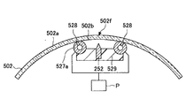
図9Aは、第6の実施形態における切断装置による切断の様子を示す上面図である。図9Bは図9AのB−B線に沿った断面図、図9Cは図9AのC−C線に沿った断面図である。 FIG. 9A is a top view showing a state of cutting by the cutting device in the sixth embodiment. 9B is a cross-sectional view taken along line BB in FIG. 9A, and FIG. 9C is a cross-sectional view taken along line CC in FIG. 9A.
切断装置510は、支持手段520と、クラック形成手段250を有する。なお、クラック形成手段250の構成は、第3の実施形態と同様であるので、説明を省略する。
The
支持手段520は、ガラス板表面502aの切断予定線504に引張応力が作用するように、ガラス板502の少なくとも一部を曲げ変形させた状態で、ガラス板502を支持する手段である。
The supporting means 520 is a means for supporting the
本実施形態の支持手段520は、ガラス板502を裏面502bから吸着支持する一対の支持管527を有する。各支持管527は、切断予定線504と平行に延びている。ガラス板502は、一対の支持管527の上に架け渡され、上に凸に湾曲した状態で一対の支持管527により支持される。よって、ガラス板502の上端部502fを曲げ変形することができ、上端部502fにある切断予定線504に引張応力を与えることができる。
The support means 520 of this embodiment includes a pair of
各支持管527の外周面527aには、複数の吸着孔528が形成されている。各吸着孔528は外部の負圧源Pと接続されている。負圧源Pは真空ポンプなどで構成され、負圧源Pが作動すると、一対の支持管527が、ガラス板502を裏面502bから吸着支持する。
A plurality of suction holes 528 are formed on the outer
一対の支持管527は、支持部材529を介して連結されており、支持部材529の中央部に電極252が固定されている。このようにして、電極252は、一対の支持管527に対して固定されている。
The pair of
電極252は、帯板状に形成され、切断予定線504に沿って延びている。電極252は、上面視において、切断予定線504の全体に重なっている。
The
電極252は、ガラス板裏面502bとの間に僅かな間隙を形成している。電極252はアースされてよい。
The
次に、上記構成とした切断装置510の動作(切断方法)について、再度図9A〜図9Cを参照して説明する。
Next, the operation (cutting method) of the
最初に、ガラス板502が支持手段520により支持される。具体的には、先ず、ガラス板502が、一対の支持管527の上に架け渡され、自然状態で平板形状のガラス板502が自重で曲げ変形して、切断予定線504に引張応力が作用する。続いて、負圧源Pが作動し、ガラス板502が、一対の支持管527に吸引支持される。
Initially, the
切断予定線504に作用する引張応力は、一対の支持管527の間の距離、ガラス板502の物性などにて定まり、例えば25〜300MPaであり、好ましくは30〜50MPaである。
The tensile stress acting on the
次いで、針形状の電極51が、ガラス板表面502aの切断予定線504の始点と対向する位置に移動される。続いて、2つの電極51、252の間に交流電力が供給され、2つの電極51、252の間に配置されるガラス板502が局所的に加熱される。その結果、ガラス板502の外周から、ガラス板502を板厚方向に貫通するクラック508が形成される。
Next, the needle-shaped
クラック508が形成されると、切断予定線504に作用していた引張応力が解放されるので、ガラス板502の切断面502c、502d同士がV字状に開く。従って、本実施形態でも、第1の実施形態と同様に、ガラス板502の切断時の変形を支援することができ、大面積のガラス板502を切断することができる。
When the
次いで、針形状の電極51が切断予定線504に沿って相対的に移動され、クラック508が切断予定線504に沿って進展する。
Next, the needle-shaped
ところで、ガラス板502は、元の形状に戻ろうとする復元力を有している。この復元力は、クラック508の形成前は、ガラス板502の左右両側に作用する重力と均衡を保っているが、クラック508の形成後は、均衡が崩れる。
By the way, the
そのため、クラック508が形成された切断箇所では、図9Cに示すように、切断箇所の左側のガラス、および、切断箇所の右側のガラスが、それぞれ、平板形状に戻ると共に、重力によって斜め下方向に移動する。その結果、V字状に開いた切断面502c、502d同士が離される。従って、本実施形態でも、第1の実施形態と同様に、切断面502c、502dの角同士が擦れ合うのを防止することができる。
Therefore, at the cut location where the
クラック508が切断予定線504の終点に到達すると、交流電力の供給が停止される。また、一対の支持管527によるガラス板502の吸引が停止され、一対の支持管527からガラス板502が取り外される。このようにして、ガラス板502を切断することができる。
When the
[第7の実施形態]
上記第1の実施形態の切断装置は、ガラス板2を裏面2bから吸着支持するステージ21を有している。
[Seventh Embodiment]
The cutting apparatus according to the first embodiment includes a
これに対し、本実施形態の切断装置は、ガラス板の両縁部を固定する一対の固定部材を有している。 On the other hand, the cutting device of this embodiment has a pair of fixing members that fix both edge portions of the glass plate.
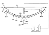
図10Aは、第7の実施形態における切断装置による切断の様子を示す下面図である。図10Bは図10AのB−B線に沿った断面図、図10Cは図10AのC−C線に沿った断面図である。 FIG. 10A is a bottom view showing a state of cutting by the cutting device according to the seventh embodiment. 10B is a cross-sectional view taken along line BB in FIG. 10A, and FIG. 10C is a cross-sectional view taken along line CC in FIG. 10A.
切断装置610は、支持手段620と、クラック形成手段250を有する。なお、クラック形成手段250の構成は、第3の実施形態と同様であるので、説明を省略する。
The
支持手段620は、ガラス板表面602aの切断予定線604に引張応力が作用するように、ガラス板602の少なくとも一部を曲げ変形させた状態で、ガラス板602を支持する手段である。
The supporting means 620 is a means for supporting the
本実施形態の支持手段620は、ガラス板602の両縁部602hを固定する一対の固定部材631を有する。ガラス板602は、下に凸に湾曲した状態で、一対の固定部材631により支持される。よって、ガラス板下面602aの下端部にある切断予定線604に引張応力を与えることができる。
The support means 620 of this embodiment includes a pair of fixing
一対の固定部材631は、支持部材632を介して連結されており、支持部材632の中央部に電極252が固定されている。このようにして、電極252は、一対の固定部材631に対して固定されている。
The pair of fixing
電極252は、帯板状に形成され、切断予定線604に沿って延びている。電極252は、上面視において、切断予定線604の全体に重なっている。
The
電極252は、ガラス板上面602bとの間に僅かな間隙を形成している。電極252はアースされてよい。
A slight gap is formed between the
次に、上記構成とした切断装置610の動作(切断方法)について、再度図10A〜図10Cを参照して説明する。
Next, the operation (cutting method) of the
最初に、ガラス板602が支持手段620により支持される。具体的には、一対の固定部材631が、ガラス板602の両縁部602hを固定した状態で、ガラス板602を下に凸に湾曲した状態で支持する。よって、ガラス板下面602aの下端部にある切断予定線604に引張応力を与えることができる。
Initially, the
切断予定線604に作用する引張応力は、一対の固定部材631の寸法形状、ガラス板602の物性などにて定まり、例えば25〜300MPaであり、好ましくは30〜50MPaである。
The tensile stress acting on the
次いで、針形状の電極51が切断予定線604の始点と対向する位置に移動される。続いて、2つの電極51、252の間に交流電力が供給され、2つの電極51、252の間に配置されるガラス板602が局所的に加熱される。その結果、ガラス板602の外周から、ガラス板602を板厚方向に貫通するクラック608が形成される。
Next, the needle-shaped
クラック608が形成されると、切断予定線604に作用していた引張応力が解放されるので、ガラス板602の切断面602c、602d同士がV字状に開く。従って、本実施形態でも、第1の実施形態と同様に、ガラス板602の切断時の変形を支援することができ、大面積のガラス板602を切断することができる。
When the
次いで、針形状の電極51が切断予定線604に沿って相対的に移動され、クラック608が切断予定線604に沿って伸展する。
Next, the needle-shaped
ところで、ガラス板602は、元の形状に戻ろうとする復元力を有している。この復元力は、クラック608の形成前は、ガラス板602の左右両側に作用する重力と均衡を保っているが、クラック608の形成後は、均衡が崩れる。
By the way, the
そのため、クラック608が形成された切断箇所では、図10Cに示すように、切断箇所の左側のガラス、および、切断箇所の右側のガラスが、それぞれ、平板形状に戻ると共に、重力によって斜め下方向に移動する。その結果、V字状に開いた切断面602c、602d同士が離される。従って、本実施形態でも、第1の実施形態と同様に、切断面602c、602dの角同士が擦れ合うのを防止することができる。
Therefore, at the cut portion where the
クラック608が切断予定線604の終点に到達すると、交流電力の供給が停止され、一対の固定部材631からガラス板602が取り外される。このようにして、ガラス板602を切断することができる。
When the
以上、本発明の第1〜第7の実施形態について説明したが、本発明は、上記の実施形態に制限されることはなく、本発明の範囲を逸脱しない範囲で、上記の実施形態に種々の変形や置換を加えることができる。 The first to seventh embodiments of the present invention have been described above. However, the present invention is not limited to the above-described embodiments, and various modifications can be made to the above-described embodiments without departing from the scope of the present invention. Can be modified or replaced.
例えば、上記のガラス板2〜602は、自然状態で平板形状に成形されているとしたが、支持手段より支持された際に、切断予定線4〜604に引張応力が作用するように曲げ変形される限り、自然状態で湾曲形状に成形されていてもよい。
For example, although the
また、上記の電極51は、回路33を介して、突起部材24、124または電極252と電気的に接続されているとしたが、接続されていなくてもよく、電極252がなくてもよい。この場合、電極51は、回路33を介してガラス板2〜602に電気的に接続され、ガラス板2〜602はアースされてよい。この場合、電極51に、高周波電源54から交流電圧、交流電流が供給される。
In addition, the
また、上記の突起部材124、電極252は、切断装置110〜610の構造の簡略化のため、帯板形状に形成され、支持手段120〜620に対して固定されているとしたが、針形状に形成され、対向配置される針形状の電極51と共に、支持手段120〜620に対して相対的に移動されてもよい。この場合、ガラス板102〜602の加熱領域を狭窄することができ、加熱効率を向上することができる。
In addition, the
また、上記のクラック形成手段50、250は、ガラス板を局所的に加熱するため、電極51を有するとしたが、電極51の代わりに、レーザ光源を有してもよい。レーザ光源としては、UVレーザ(波長:355nm)、グリーンレーザ(波長:532nm)、半導体レーザ(波長:808nm、940nm、975nm)、ファイバーレーザ(波長:1060〜1100nm)、YAGレーザ(波長:1064nm、2080nm、2940nm)などが挙げられる。レーザ光源の場合、電極252は不要である。
In addition, the
また、上記のクラック形成手段50、250は、ガラス板に温度勾配をつけるため、ガラス板を局所的に冷却する冷却源を有していてもよい。冷却源としては、例えば冷媒を吐出するノズルが用いられる。冷媒としては、冷却空気などのガス、冷水などの液体が用いられる。ガスと液体を組み合わせて用いても良い。
Further, the
2 ガラス板(脆性板)
2a ガラス板表面
2b ガラス板裏面
2c 切断面
2d 切断面
4 切断予定線
8 クラック
10 切断装置
20 支持手段
21 ステージ
21a 支持面
23 吸着孔
24 突起部材
50 クラック形成手段
51 電極
125 押圧部材
252 電極
527 支持管
631 固定部材
2 Glass plate (brittle plate)
2a
Claims (13)
前記第1のステップでは、前記脆性板表面の切断予定線に引張応力が作用するように、前記脆性板の少なくとも一部を曲げ変形させた状態で、前記脆性板を前記支持手段により支持することを特徴とする脆性板の切断方法。 A first step of supporting the brittle plate by the supporting means; and locally heating the brittle plate supported by the supporting means and moving the heating area of the brittle plate to move the brittle plate in the plate thickness direction. In a method for cutting a brittle plate having a second step of forming a crack that penetrates and extending the crack,
In the first step, the brittle plate is supported by the support means in a state where at least a part of the brittle plate is bent and deformed so that a tensile stress acts on a planned cutting line of the brittle plate surface. A method of cutting a brittle plate characterized by the above.
前記支持手段は、前記脆性板の前記ステージからはみ出す端部を表面側から裏面側に向けて押圧する押圧部材をさらに有する請求項3に記載の脆性板の切断方法。 The protruding member protrudes from a side edge portion of the support surface of the stage,
The said support means is a cutting method of the brittle board of Claim 3 which further has a press member which presses the edge part which protrudes from the said stage of the said brittle board toward the back surface side from the surface side.
前記第2のステップでは、前記空間に負圧を生じさせることにより、前記脆性板の切断面同士を離間させる請求項3または4に記載の脆性板の切断方法。 A space surrounded by the support surface of the stage, the protruding member, and the back surface of the brittle plate is connected to a negative pressure source through an adsorption hole formed in the support surface of the stage,
The method for cutting a brittle plate according to claim 3 or 4, wherein in the second step, the cut surfaces of the brittle plate are separated from each other by generating a negative pressure in the space.
前記第2のステップでは、
前記突起部材と、前記突起部材に電気的に接続される電極との間に交流電力を供給することにより、前記突起部材と前記電極の間に配置される前記脆性板を局所的に加熱すると共に、
前記支持手段により支持される前記脆性板に対し前記電極を相対的に移動させることにより、前記脆性板の加熱領域を移動させる請求項3〜5のいずれか一項に記載の切断方法。 The protruding member has conductivity, the stage has insulating properties,
In the second step,
By supplying AC power between the protruding member and an electrode electrically connected to the protruding member, the brittle plate disposed between the protruding member and the electrode is locally heated. ,
The cutting method according to any one of claims 3 to 5, wherein a heating region of the brittle plate is moved by moving the electrode relative to the brittle plate supported by the support means.
前記脆性板は、前記一対の支持管の上に架け渡され、上に凸に湾曲した状態で前記一対の支持管により支持される請求項1に記載の脆性板の切断方法。 The support means has a pair of support pipes for adsorbing and supporting the brittle plate from the back surface, and each support tube extends in parallel with a planned cutting line of the brittle plate back surface,
The method for cutting a brittle plate according to claim 1, wherein the brittle plate is stretched over the pair of support tubes and is supported by the pair of support tubes in a state of being convexly curved upward.
前記脆性板は、下に凸に湾曲した状態で、前記一対の固定部材により支持される請求項1に記載の脆性板の切断方法。 The support means has a pair of fixing members that fix both edges of the brittle plate,
The method for cutting a brittle plate according to claim 1, wherein the brittle plate is supported by the pair of fixing members in a state of being convexly curved downward.
前記支持手段により支持される脆性板の両側に配置される2つの電極の間に交流電力を供給することにより、前記2つ電極の間に配置される前記脆性板を局所的に加熱すると共に、
前記支持手段により支持される前記脆性板に対し、少なくとも一方の電極を相対的に移動させることにより、前記脆性板の加熱領域を移動させる請求項7〜11のいずれか一項に記載の脆性板の切断方法。 In the second step,
By supplying AC power between the two electrodes arranged on both sides of the brittle plate supported by the supporting means, the brittle plate arranged between the two electrodes is locally heated,
The brittle plate according to any one of claims 7 to 11, wherein a heating region of the brittle plate is moved by moving at least one electrode relative to the brittle plate supported by the support means. Cutting method.
前記支持手段は、前記脆性板表面の切断予定線に引張応力が作用するように、前記脆性板の少なくとも一部を曲げ変形させた状態で、前記脆性板を支持することを特徴とする脆性板の切断装置。 Forming a crack penetrating the brittle plate in the thickness direction by locally heating the brittle plate supported by the support means and moving the heating area of the brittle plate while supporting the brittle plate And a brittle plate cutting device having crack forming means for extending the cracks,
The brittle plate is characterized in that the support means supports the brittle plate in a state where at least a part of the brittle plate is bent and deformed so that a tensile stress acts on a planned cutting line on the surface of the brittle plate. Cutting device.
Priority Applications (3)
| Application Number | Priority Date | Filing Date | Title |
|---|---|---|---|
| JP2011069794A JP2012201573A (en) | 2011-03-28 | 2011-03-28 | Device and method for cutting brittle plate |
| PCT/JP2012/056910 WO2012132974A1 (en) | 2011-03-28 | 2012-03-16 | Apparatus for cutting brittle sheet and method for cutting brittle sheet |
| TW101110265A TW201245064A (en) | 2011-03-28 | 2012-03-23 | Apparatus for cutting brittle sheet and method for cutting brittle sheet |
Applications Claiming Priority (1)
| Application Number | Priority Date | Filing Date | Title |
|---|---|---|---|
| JP2011069794A JP2012201573A (en) | 2011-03-28 | 2011-03-28 | Device and method for cutting brittle plate |
Publications (1)
| Publication Number | Publication Date |
|---|---|
| JP2012201573A true JP2012201573A (en) | 2012-10-22 |
Family
ID=46930707
Family Applications (1)
| Application Number | Title | Priority Date | Filing Date |
|---|---|---|---|
| JP2011069794A Withdrawn JP2012201573A (en) | 2011-03-28 | 2011-03-28 | Device and method for cutting brittle plate |
Country Status (3)
| Country | Link |
|---|---|
| JP (1) | JP2012201573A (en) |
| TW (1) | TW201245064A (en) |
| WO (1) | WO2012132974A1 (en) |
Cited By (4)
| Publication number | Priority date | Publication date | Assignee | Title |
|---|---|---|---|---|
| WO2017023052A1 (en) * | 2015-07-31 | 2017-02-09 | 코닝정밀소재 주식회사 | Method and apparatus for cutting glass laminate |
| WO2018066508A1 (en) * | 2016-10-05 | 2018-04-12 | 日本電気硝子株式会社 | Method for producing glass resin laminate, and glass resin laminate |
| WO2022153859A1 (en) * | 2021-01-12 | 2022-07-21 | 日本電気硝子株式会社 | Method for producing glass film |
| WO2024004545A1 (en) * | 2022-06-28 | 2024-01-04 | 日東電工株式会社 | Method and device for dividing sheet material |
Families Citing this family (7)
| Publication number | Priority date | Publication date | Assignee | Title |
|---|---|---|---|---|
| JP6014490B2 (en) * | 2012-12-27 | 2016-10-25 | 三星ダイヤモンド工業株式会社 | Cutting method and device |
| JP2014162682A (en) * | 2013-02-26 | 2014-09-08 | Nippon Electric Glass Co Ltd | Cutting method of glass film, glass film cutting apparatus and glass film |
| CN105143123B (en) * | 2013-07-08 | 2018-06-29 | 川崎重工业株式会社 | The method for dividing and break-up device of the plank of fragile material |
| EP2990172A1 (en) * | 2014-08-26 | 2016-03-02 | Fraunhofer-Gesellschaft zur Förderung der angewandten Forschung e.V. | Method for splitting of plate-shaped objects made of brittle materials |
| JP7022389B2 (en) * | 2018-05-31 | 2022-02-18 | 日本電気硝子株式会社 | Glass film manufacturing method |
| CN109795038B (en) * | 2019-01-22 | 2021-07-06 | Tcl华星光电技术有限公司 | Cutting device and substrate edge terminal removing device adopting same |
| EP3695944B1 (en) * | 2019-02-12 | 2024-04-24 | Fraunhofer-Gesellschaft zur Förderung der angewandten Forschung e.V. | Method and device for splitting of plate-shaped objects made of brittle materials |
Family Cites Families (3)
| Publication number | Priority date | Publication date | Assignee | Title |
|---|---|---|---|---|
| JP2006137641A (en) * | 2004-11-12 | 2006-06-01 | Sanyo Electric Co Ltd | Cutting method of glass substrate |
| JP2008088012A (en) * | 2006-10-02 | 2008-04-17 | Matsushita Electric Ind Co Ltd | Method and apparatus for cutting glass substrate |
| JP5376282B2 (en) * | 2008-03-25 | 2013-12-25 | 日本電気硝子株式会社 | Glass plate folding method and glass plate folding device |
-
2011
- 2011-03-28 JP JP2011069794A patent/JP2012201573A/en not_active Withdrawn
-
2012
- 2012-03-16 WO PCT/JP2012/056910 patent/WO2012132974A1/en active Application Filing
- 2012-03-23 TW TW101110265A patent/TW201245064A/en unknown
Cited By (6)
| Publication number | Priority date | Publication date | Assignee | Title |
|---|---|---|---|---|
| WO2017023052A1 (en) * | 2015-07-31 | 2017-02-09 | 코닝정밀소재 주식회사 | Method and apparatus for cutting glass laminate |
| US10737968B2 (en) | 2015-07-31 | 2020-08-11 | Corning Precision Materials Co., Ltd | Method and apparatus for cutting a glass laminate |
| WO2018066508A1 (en) * | 2016-10-05 | 2018-04-12 | 日本電気硝子株式会社 | Method for producing glass resin laminate, and glass resin laminate |
| JPWO2018066508A1 (en) * | 2016-10-05 | 2019-07-18 | 日本電気硝子株式会社 | Method of manufacturing glass resin laminate and glass resin laminate |
| WO2022153859A1 (en) * | 2021-01-12 | 2022-07-21 | 日本電気硝子株式会社 | Method for producing glass film |
| WO2024004545A1 (en) * | 2022-06-28 | 2024-01-04 | 日東電工株式会社 | Method and device for dividing sheet material |
Also Published As
| Publication number | Publication date |
|---|---|
| WO2012132974A1 (en) | 2012-10-04 |
| TW201245064A (en) | 2012-11-16 |
Similar Documents
| Publication | Publication Date | Title |
|---|---|---|
| WO2012132974A1 (en) | Apparatus for cutting brittle sheet and method for cutting brittle sheet | |
| JP6260869B2 (en) | Manufacturing method of glass film and manufacturing method of electronic device including the glass film | |
| WO2013151075A1 (en) | Glass film fracturing method and glass film laminate body | |
| US10829404B2 (en) | Method for cutting plate-like glass, and cutting device therefor | |
| US9458047B2 (en) | Method for cutting plate-like glass, and cutting device therefor | |
| US20160151929A1 (en) | Method of and apparatus for dividing plate member made of brittle material | |
| US10168561B2 (en) | Device and method for stripping flexible substrate | |
| WO2014030521A1 (en) | Method for cutting composite sheet, method for cutting glass sheet, and cut piece of composite sheet | |
| EP2048705A3 (en) | Manufacturing method of SOI substrate | |
| US9908806B2 (en) | Sheet glass, method for manufacturing sheet glass, and device for manufacturing sheet glass | |
| TWI610893B (en) | Fitting device for bonding substrates | |
| JP2008201629A (en) | Manufacturing method of electrooptical device, separating method of substrate, and substrate separating device | |
| JP2012255134A (en) | Hardboard lamination method and module coated therewith | |
| WO2012118083A1 (en) | Cutting method for glass plate member, and cutting device | |
| KR101420627B1 (en) | cutting apparatus using heating for glass panel | |
| WO2017018136A1 (en) | Method for producing glass film, and method for producing electronic device including glass film | |
| JP6075567B2 (en) | Laminate peeling apparatus, peeling method, and electronic device manufacturing method | |
| JP2012193060A (en) | Cutting device for fragile plate and cutting method for fragile plate | |
| JP2011049291A (en) | Electrode member for anodic bonding, and anodic bonding apparatus with the same | |
| CN105388651A (en) | Method for manufacturing liquid crystal display panel | |
| JP2009154516A6 (en) | Brittle substrate cutting aid | |
| JP6445863B2 (en) | Method and apparatus for dividing plate material of brittle material | |
| JP2016060135A (en) | Glass film laminate, and production method of electronic device | |
| KR20170076160A (en) | Apparatus for processing flexible substrate and processing method thereof | |
| JP4644301B1 (en) | Daylighting heat insulating material manufacturing apparatus and daylighting heat insulating material manufacturing method |
Legal Events
| Date | Code | Title | Description |
|---|---|---|---|
| A300 | Withdrawal of application because of no request for examination |
Free format text: JAPANESE INTERMEDIATE CODE: A300 Effective date: 20140603 |