JP2012194426A - Developing device and image forming device - Google Patents

Developing device and image forming device Download PDF

Info

Publication number
JP2012194426A
JP2012194426A JP2011059074A JP2011059074A JP2012194426A JP 2012194426 A JP2012194426 A JP 2012194426A JP 2011059074 A JP2011059074 A JP 2011059074A JP 2011059074 A JP2011059074 A JP 2011059074A JP 2012194426 A JP2012194426 A JP 2012194426A
Authority
JP
Japan
Prior art keywords
roller
supply roller
developer
liquid developer
unit
Prior art date
Legal status (The legal status is an assumption and is not a legal conclusion. Google has not performed a legal analysis and makes no representation as to the accuracy of the status listed.)
Withdrawn
Application number
JP2011059074A
Other languages
Japanese (ja)
Inventor
Kazuma Miyazawa
一真 宮澤
Tsutomu Sasaki
努 佐々木
Kazuhiro Nishiyama
和宏 西山
Naoyuki Okumura
尚之 奥村
Current Assignee (The listed assignees may be inaccurate. Google has not performed a legal analysis and makes no representation or warranty as to the accuracy of the list.)
Seiko Epson Corp
Original Assignee
Seiko Epson Corp
Priority date (The priority date is an assumption and is not a legal conclusion. Google has not performed a legal analysis and makes no representation as to the accuracy of the date listed.)
Filing date
Publication date
Application filed by Seiko Epson Corp filed Critical Seiko Epson Corp
Priority to JP2011059074A priority Critical patent/JP2012194426A/en
Priority to US13/397,267 priority patent/US20120237266A1/en
Publication of JP2012194426A publication Critical patent/JP2012194426A/en
Withdrawn legal-status Critical Current

Links

Images

Classifications

    • GPHYSICS
    • G03PHOTOGRAPHY; CINEMATOGRAPHY; ANALOGOUS TECHNIQUES USING WAVES OTHER THAN OPTICAL WAVES; ELECTROGRAPHY; HOLOGRAPHY
    • G03GELECTROGRAPHY; ELECTROPHOTOGRAPHY; MAGNETOGRAPHY
    • G03G15/00Apparatus for electrographic processes using a charge pattern
    • G03G15/06Apparatus for electrographic processes using a charge pattern for developing
    • G03G15/10Apparatus for electrographic processes using a charge pattern for developing using a liquid developer
    • G03G15/104Preparing, mixing, transporting or dispensing developer

Abstract

PROBLEM TO BE SOLVED: To finely apply a liquid developer on a developer carrier roller by accurately driving a first supply roller, a second supply roller, and the developer carrier roller with two driving sources, when the liquid developer stored in a storage portion in a developer container is supplied to the developer carrier roller through the first supply roller and the second supply roller.SOLUTION: Driving force generated by a first drive motor M1 is added to a developing roller 51 and an intermediate applying roller 52 by a first drive transmitting portion 55 to make them rotate. Both of the developing roller 51 and the intermediate applying roller 52 uses the first drive motor M1 as a driving source and receive the driving force from the first drive motor M1 through the same first drive transmitting portion 55, so that phases of fluctuations of rotation components of the first drive motor M1 and meshing periodic variations of gears. Consequently, a rotation circumferential speed difference between the developing roller 51 and the intermediate applying roller 52 becomes small.

Description

この発明は、トナーおよびキャリア液体を含む液体現像剤で現像する現像装置および該現像装置を装備する画像形成装置に関するものである。   The present invention relates to a developing device for developing with a liquid developer containing toner and carrier liquid, and an image forming apparatus equipped with the developing device.

従来、帯電している感光体に静電潜像を形成し、キャリア液体にトナーを分散した液体現像剤により静電潜像を現像してトナー像を形成する液体現像方式の画像形成装置が実用化されている。例えば特許文献1に記載の画像形成装置で採用されている現像装置では、現像ローラー用モーターによって回転駆動される現像ローラーに担持させるための液体現像剤を貯留する供給部が現像剤容器に設けられている。そして、螺旋状等の溝による凹凸面を形成したアニロクスローラーが現像ローラーに当接するとともに上記モーターと異なるアニロクスローラー用モーターによって回転駆動されて現像剤容器の供給部から現像ローラーへの液体現像剤の供給を行っている。   Conventionally, a liquid developing type image forming apparatus that forms an electrostatic latent image on a charged photoreceptor and develops the electrostatic latent image with a liquid developer in which toner is dispersed in a carrier liquid to form a toner image is practical. It has become. For example, in the developing device employed in the image forming apparatus described in Patent Document 1, a developer container is provided in the developer container for storing a liquid developer to be carried on a developing roller that is rotationally driven by a developing roller motor. ing. Then, an anilox roller having a concave and convex surface formed by a groove such as a spiral comes into contact with the developing roller and is rotated by a motor for an anilox roller different from the above motor to develop liquid from the developer container supply unit to the developing roller. The agent is supplied.

特開2009−204973号公報(図2)JP 2009-204973 A (FIG. 2)

ところで、上記現像装置は、アニロクスローラーが現像ローラーに当接するとともに回転して現像ローラーに液体現像剤を供給する、いわゆる2ローラー構造を採用しているが、現像ローラーの保護に観点から両者の間に中間塗布ローラーを介在させた、いわゆる3ローラー構造が提案されている。ここで、中間塗布ローラーを回転駆動するためのモーターをさらに追加すると、装置コストの増大を招くのみならず、追加モーターの発熱による影響を考慮する必要があり、現像装置、さらには当該現像装置を装備する画像形成装置全体に関わる対策が必要になる。そこで、3ローラー構造においても2台でのモーターによって各ローラーを高精度に駆動させて容器内の液体現像剤を現像ローラーに良好に供給するための技術が要望されている。   By the way, the developing device employs a so-called two-roller structure in which the anilox roller abuts on the developing roller and rotates to supply the liquid developer to the developing roller. A so-called three-roller structure has been proposed in which an intermediate coating roller is interposed therebetween. Here, if a motor for rotationally driving the intermediate application roller is further added, not only will the apparatus cost increase, but it is necessary to consider the influence of heat generated by the additional motor. It is necessary to take measures for the entire image forming apparatus to be equipped. Therefore, there is a demand for a technique for satisfactorily supplying the liquid developer in the container to the developing roller by driving each roller with high accuracy by two motors even in a three-roller structure.

この発明にかかるいくつかの態様は、現像剤容器の貯留部に貯留される液体現像剤を第1供給ローラーおよび第2供給ローラーを介して現像剤担持体ローラーに供給する、いわゆる3ローラー構造の現像装置および当該現像装置を装備する画像形成装置において、2つの駆動源により第1供給ローラー、第2供給ローラーおよび現像剤担持体ローラーを高精度に駆動して現像剤担持体ローラーに液体現像剤を良好に塗布する技術を提供することを目的とする。   Some embodiments according to the present invention have a so-called three-roller structure in which the liquid developer stored in the storage portion of the developer container is supplied to the developer carrier roller via the first supply roller and the second supply roller. In a developing device and an image forming apparatus equipped with the developing device, the first supply roller, the second supply roller, and the developer carrier roller are driven with high accuracy by two drive sources, and the liquid developer is supplied to the developer carrier roller. An object of the present invention is to provide a technique for satisfactorily applying the coating.

この発明の第1の態様は、現像装置であって、トナーおよびキャリア液を含む液体現像剤を貯留する貯留部と、回転して貯留部に貯留される液体現像剤を担持する第1供給ローラーと、第1供給ローラーと当接するとともに回転して第1供給ローラーから液体現像剤が供給される第2供給ローラーと、第2供給ローラーと当接するとともに回転して第2供給ローラーから供給される液体現像剤を担持する現像剤担持体ローラーと、現像剤担持体ローラーと第2供給ローラーを駆動させる第1駆動源と、第1供給ローラーを駆動させる第2駆動源と、を備えることを特徴としている。   1st aspect of this invention is a developing device, Comprising: The storage part which stores the liquid developer containing a toner and carrier liquid, The 1st supply roller which carries | supports the liquid developer rotated and stored in a storage part And a second supply roller that contacts and rotates with the first supply roller and is supplied with the liquid developer from the first supply roller, and rotates and is supplied with the second supply roller from the second supply roller. A developer carrying roller for carrying the liquid developer, a first drive source for driving the developer carrier roller and the second supply roller, and a second drive source for driving the first supply roller. It is said.

また、この発明の第2の態様は、画像形成装置であって、潜像が形成される潜像担持体と、トナーおよびキャリア液を含む液体現像剤を貯留する貯留部、回転して貯留部に貯留される液体現像剤を担持する第1供給ローラー、第1供給ローラーと当接するとともに回転して第1供給ローラーから液体現像剤が供給される第2供給ローラー、及び第2供給ローラーと当接するとともに回転して第2供給ローラーから供給される液体現像剤を担持する現像剤担持体ローラーを有し、潜像担持体に形成された潜像を現像する現像部と、現像剤担持体ローラーと第2供給ローラーを駆動させる第1駆動源と、第1供給ローラーを駆動させる第2駆動源と、を備えることを特徴としている。   According to a second aspect of the present invention, there is provided an image forming apparatus comprising: a latent image carrier on which a latent image is formed; a storage unit that stores a liquid developer including toner and carrier liquid; The first supply roller carrying the liquid developer stored in the first supply roller, the second supply roller contacting the first supply roller and rotating to supply the liquid developer from the first supply roller, and the second supply roller. A developer carrying roller having a developer carrying roller for carrying a liquid developer supplied from a second supply roller in contact with and rotating, and for developing a latent image formed on the latent image carrying body; and a developer carrying roller And a first drive source that drives the second supply roller, and a second drive source that drives the first supply roller.

このように構成された発明(現像装置および画像形成装置)では、貯留部に貯留される液体現像剤が第1供給ローラーにより第2供給ローラーに供給され、さらに第2供給ローラーから現像剤担持体ローラーに供給される。そして、これらのうち、現像剤担持体ローラーと第2供給ローラーは第1駆動源により駆動されるため、現像剤担持体ローラーおよび第2供給ローラーの回転周速の誤差は小さくなる。また、第1供給ローラーが第1駆動源と異なる第2駆動源により駆動されるため、第2供給ローラーの回転周速と異なる回転周速で第1供給ローラーを駆動することができ、現像剤担持体ローラーへの液体現像剤の供給量を調整可能となっている。つまり、第1供給ローラーおよび第2供給ローラーの回転周速差に基づき第1供給ローラーから第2供給ローラーに供給される液体現像剤の供給量が調整され、それによって第2供給ローラーから現像剤担持体ローラーに供給される液体現像剤の量を調整可能となっており、現像剤担持体ローラーに液体現像剤を良好に塗布することができる。   In the invention thus configured (developing apparatus and image forming apparatus), the liquid developer stored in the storage unit is supplied to the second supply roller by the first supply roller, and further from the second supply roller to the developer carrier. Supplied to the roller. Among these, since the developer carrier roller and the second supply roller are driven by the first drive source, the error in the rotational peripheral speed between the developer carrier roller and the second supply roller becomes small. Further, since the first supply roller is driven by a second drive source different from the first drive source, the first supply roller can be driven at a rotational peripheral speed different from the rotational peripheral speed of the second supply roller, and the developer The supply amount of the liquid developer to the carrier roller can be adjusted. That is, the supply amount of the liquid developer supplied from the first supply roller to the second supply roller is adjusted based on the rotational peripheral speed difference between the first supply roller and the second supply roller, and thereby the developer is supplied from the second supply roller. The amount of the liquid developer supplied to the carrier roller can be adjusted, and the liquid developer can be satisfactorily applied to the developer carrier roller.

ここで、第1駆動源で発生する駆動力を現像剤担持体ローラーおよび第2供給ローラーに伝達し、現像剤担持体ローラーを回転させるとともに、現像剤担持体ローラーの回転方向と同じ方向に回転させ、かつ現像剤担持体ローラーの回転周速と同じ、もしくは現像剤担持体ローラーの回転周速よりも速く第2供給ローラーを回転させる駆動伝達部を備えてもよい。   Here, the driving force generated by the first drive source is transmitted to the developer carrier roller and the second supply roller to rotate the developer carrier roller and rotate in the same direction as the rotation direction of the developer carrier roller. And a drive transmission unit that rotates the second supply roller at the same rotational rotational speed of the developer carrier roller or faster than the rotational circumferential speed of the developer carrier roller.

また、駆動伝達部は、第1駆動源の回転軸と同軸に配設された第1の駆動伝達部材、及び現像剤担持体ローラーの回転軸と同軸に配設されて第1の駆動伝達部材と接続された第2の駆動伝達部材を有してもよい。   In addition, the drive transmission unit includes a first drive transmission member disposed coaxially with the rotation shaft of the first drive source, and a first drive transmission member disposed coaxially with the rotation shaft of the developer carrier roller. And a second drive transmission member connected to the.

また、第2駆動源で発生された駆動力により、第1供給ローラーは第2供給ローラーの回転方向と逆方向に回転し、かつ第2供給ローラーの回転周速よりも遅く回転するように構成してもよい。   Further, the first supply roller is configured to rotate in a direction opposite to the rotation direction of the second supply roller by the driving force generated by the second drive source, and to rotate slower than the rotation peripheral speed of the second supply roller. May be.

第1供給ローラーの回転周速を調整する調整部を備えてもよい。   You may provide the adjustment part which adjusts the rotational peripheral speed of a 1st supply roller.

また、貯留部に配設され、第1駆動源で発生する駆動力を受けて回転して貯留部に貯留される液体現像剤を撹拌する撹拌部材を備えてもよい。   Further, an agitation member may be provided that is disposed in the storage unit and rotates by receiving a driving force generated by the first drive source and stirs the liquid developer stored in the storage unit.

さらに、現像剤担持体ローラーをクリーニングして液体現像剤を回収するクリーニング部と、クリーニング部で回収された液体現像剤を貯留する回収部と、回収部に配設され、第2駆動源で発生する駆動力を受けて回転して回収部に回収された液体現像剤を搬送する搬送部材と、を備えてもよい。   Furthermore, a cleaning unit that cleans the developer carrier roller to recover the liquid developer, a recovery unit that stores the liquid developer recovered by the cleaning unit, and a recovery unit that are disposed in the recovery unit and are generated by the second drive source And a conveying member that rotates and receives the liquid developer collected in the collecting unit by receiving the driving force.

本発明にかかる現像装置の第1実施形態を装備した画像形成装置を示す図。1 is a diagram illustrating an image forming apparatus equipped with a first embodiment of a developing device according to the present invention. FIG. 本発明の現像装置の第1実施形態たる現像部を示す図。FIG. 3 is a diagram illustrating a developing unit according to the first embodiment of the developing device of the present invention. 第1駆動モーターおよび第1駆動伝達部の構成を示す図。The figure which shows the structure of a 1st drive motor and a 1st drive transmission part. 第2駆動モーターおよび第2駆動伝達部の構成を示す図。The figure which shows the structure of a 2nd drive motor and a 2nd drive transmission part. 現像ローラーと中間塗布ローラーとの回転周速差を示す図。The figure which shows the rotational peripheral speed difference of a developing roller and an intermediate application roller. 位相差と回転周速の変動率との関係を示すグラフ。The graph which shows the relationship between a phase difference and the fluctuation rate of rotational peripheral speed. 中間塗布ローラーが現像ローラーおよびアニロックスローラーから受ける力を解析した図。The figure which analyzed the force which an intermediate application roller receives from a developing roller and an anilox roller. 中間塗布ローラーの回転周速の変動率を示すグラフ。The graph which shows the fluctuation | variation rate of the rotational peripheral speed of an intermediate application roller. 駆動源に相違による貯留部での液面レベルの様子を示す模式図。The schematic diagram which shows the mode of the liquid level in the storage part by a difference in a drive source. 本発明にかかる現像装置の第2実施形態を示す図。FIG. 9 is a diagram illustrating a second embodiment of the developing device according to the invention. 図10の装置の部分拡大斜視図。FIG. 11 is a partially enlarged perspective view of the apparatus of FIG. 10.

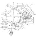
図1は本発明にかかる現像装置の第1実施形態を装備した画像形成装置を示す図である。この画像形成装置は、感光体ドラム1の回転中心を通る仮想水平面HPの鉛直方向の下方で、感光体ドラム1に担持される像を1次転写部2のブランケットローラー21に転写し、さらにブランケットローラー21に転写された像を転写紙に転写する、いわゆる下部転写構造を有している。なお、図1の画像形成装置は後述するように単色のトナー像を形成して転写紙に転写するものであり、同装置を複数台、例えば4台配列してカラー印刷システムを構成することが可能である。もちろん、図1の装置は単独でモノクロの画像形成装置としても機能する。   FIG. 1 is a diagram showing an image forming apparatus equipped with a first embodiment of a developing device according to the present invention. The image forming apparatus transfers an image carried on the photosensitive drum 1 to the blanket roller 21 of the primary transfer unit 2 below the virtual horizontal plane HP passing through the rotation center of the photosensitive drum 1, and further blankets. It has a so-called lower transfer structure in which the image transferred to the roller 21 is transferred to transfer paper. The image forming apparatus shown in FIG. 1 forms a single color toner image and transfers it onto a transfer sheet as will be described later. A plurality of, for example, four such apparatuses can be arranged to constitute a color printing system. Is possible. Of course, the apparatus of FIG. 1 also functions as a monochrome image forming apparatus by itself.

この画像形成装置では、感光体ドラム1は、アモルファスシリコン感光体などの感光体材料からなる感光層を表面に有している。そして、その回転軸が主走査方向(図1の紙面に対して垂直な方向)に平行もしくは略平行となるように感光体ドラム1は配置されており、図1中矢印D1の方向に所定速度で回転駆動される。   In this image forming apparatus, the photosensitive drum 1 has a photosensitive layer made of a photosensitive material such as an amorphous silicon photosensitive member on the surface. The photosensitive drum 1 is arranged so that the rotation axis thereof is parallel or substantially parallel to the main scanning direction (perpendicular to the paper surface of FIG. 1), and a predetermined speed is indicated in the direction of arrow D1 in FIG. Is driven to rotate.

感光体ドラム1の周囲には、感光体ドラム1表面を所定の電位に帯電させる帯電部3と、感光体ドラム1表面を画像信号に応じて露光することで静電潜像を形成する露光部4と、該静電潜像を液体現像剤で現像してトナー像を形成する現像部5と、第1スクイーズ部6と、第2スクイーズ部7と、1次転写部2のブランケットローラー21と、一次転写後の感光体ドラム1の表面をクリーニングする感光体クリーニング部8とが、それぞれこれらの順に感光体ドラム1の回転方向D1(図1では、反時計回り)に沿って配設されている。   Around the photosensitive drum 1, a charging unit 3 that charges the surface of the photosensitive drum 1 to a predetermined potential, and an exposure unit that forms an electrostatic latent image by exposing the surface of the photosensitive drum 1 according to an image signal. 4, a developing unit 5 that develops the electrostatic latent image with a liquid developer to form a toner image, a first squeeze unit 6, a second squeeze unit 7, and a blanket roller 21 of the primary transfer unit 2. A photosensitive member cleaning unit 8 for cleaning the surface of the photosensitive drum 1 after the primary transfer is disposed along the rotation direction D1 (counterclockwise in FIG. 1) of the photosensitive drum 1 in this order. Yes.

帯電部3は、6個の帯電器31と帯電器気流ダクト32とを有しており、図1紙面において、感光体ドラム1の回転中心を通る仮想鉛直面VPに対して右側で、しかも感光体ドラム1の回転中心を通る仮想水平面HPに対して鉛直方向の下方に配されている。これらの帯電器31は感光体ドラム1の表面に接触しないものであり、感光体ドラム1の回転方向D1に沿って6個配列されている。帯電器31としては、例えば従来周知慣用のコロナ帯電器を用いることができる。コロナ帯電器にスコロトロン帯電器を用いた場合には、スコロトロン帯電器のチャージワイヤにはワイヤ電流が流されるとともに、グリッドには直流(DC)のグリッド帯電バイアスが印加される。このように帯電器31によるコロナ放電で感光体ドラム1が帯電されることで、感光体ドラム1の表面の電位が略均一の電位に設定される。また、帯電器気流ダクト32は帯電器31に向けて外気を導入する外気導入経路(図示省略)と、帯電器31での放電により発生する雰囲気を排気する排気経路(図示省略)とを有しており、帯電処理が行われる雰囲気を換気して雰囲気管理を行う。   The charging unit 3 includes six chargers 31 and a charger airflow duct 32. On the paper surface of FIG. 1, the charging unit 3 is on the right side with respect to a virtual vertical plane VP passing through the rotation center of the photosensitive drum 1, and is also photosensitive. It is arranged below in the vertical direction with respect to a virtual horizontal plane HP passing through the center of rotation of the body drum 1. These chargers 31 are not in contact with the surface of the photosensitive drum 1, and six chargers 31 are arranged along the rotation direction D <b> 1 of the photosensitive drum 1. As the charger 31, for example, a conventionally well-known corona charger can be used. When a scorotron charger is used as the corona charger, a wire current flows through the charge wire of the scorotron charger and a direct current (DC) grid charging bias is applied to the grid. In this way, the photosensitive drum 1 is charged by corona discharge by the charger 31, so that the surface potential of the photosensitive drum 1 is set to a substantially uniform potential. The charger airflow duct 32 has an outside air introduction path (not shown) for introducing outside air toward the charger 31 and an exhaust path (not shown) for exhausting the atmosphere generated by the discharge at the charger 31. The atmosphere is controlled by ventilating the atmosphere in which the charging process is performed.

露光部4は、図1紙面において仮想鉛直面VPに対して右側で、しかも仮想水平面HP上に配されて外部装置から与えられた画像信号に応じて光ビームにより感光体ドラム1表面を露光して画像信号に対応する静電潜像を形成する。本実施形態では、この露光部4として発光素子を主走査方向(図1紙面に垂直な方向)に配列したラインヘッドを用いているが、これ以外に半導体レーザからの光ビームをポリゴンミラーにより主走査方向に走査させるもの等を用いてもよい。なお、本実施形態では、露光部4を仮想水平面HP上に配しているが、露光部4の配設位置はこれに限定されるものではなく、仮想水平面HPの鉛直方向の上方または下方に配してもよい。   The exposure unit 4 exposes the surface of the photosensitive drum 1 with a light beam in accordance with an image signal provided on the virtual horizontal plane HP on the right side of the virtual vertical plane VP in FIG. 1 and provided on the virtual horizontal plane HP. Thus, an electrostatic latent image corresponding to the image signal is formed. In the present embodiment, a line head in which light emitting elements are arranged in the main scanning direction (direction perpendicular to the paper surface of FIG. 1) is used as the exposure unit 4, but in addition to this, the light beam from the semiconductor laser is mainly output by a polygon mirror. You may use what scans in a scanning direction. In the present embodiment, the exposure unit 4 is arranged on the virtual horizontal plane HP, but the arrangement position of the exposure unit 4 is not limited to this, and is above or below the vertical direction of the virtual horizontal plane HP. It may be arranged.

こうして形成された静電潜像に対し、本発明にかかる現像装置の第1実施形態たる現像部5から液体現像剤が付与されて、静電潜像がトナーにより現像される。本実施形態では、絶縁性液体を主成分とするキャリア液体内に、着色された樹脂粒子をトナーとして概略重量比25%程度に分散させた液体現像剤を用いており、トナーは電界中を電気泳動可能なように電荷を有している。なお、この現像剤濃度については、上記25%に限定されるものではなく、10〜30%であってもよい。また、キャリア液体としては、例えばIsopar(エクソン社商標)、シリコンオイル、ノルマルパラフィンオイルなどが使用される。また、電気抵抗値は1010Ω・cm以上、望ましくは1012Ω・cm以上が好ましい。というのも、抵抗が低い場合には、トナーが電気泳動する過程で余剰な電流が流れ、移動に必要な電界が維持できない可能性があるからである。さらに、こうして調製された液体現像剤の粘度は、トナーを構成する樹脂や分散剤・荷電制御剤で左右されるが、50〜500[mPa・s]の粘度を示す液体現像剤を用いることができ、本実施形態では400[mPa・s]の液体現像剤を用いている。なお、現像部5の構成および動作については、後で詳述する。 A liquid developer is applied to the electrostatic latent image formed in this way from the developing unit 5 which is the first embodiment of the developing device according to the present invention, and the electrostatic latent image is developed with toner. In the present embodiment, a liquid developer in which colored resin particles are dispersed as a toner in a weight ratio of about 25% in a carrier liquid containing an insulating liquid as a main component is used. It has a charge so that it can migrate. The developer concentration is not limited to 25%, but may be 10 to 30%. As the carrier liquid, for example, Isopar (trademark of Exxon), silicon oil, normal paraffin oil, or the like is used. The electric resistance value is preferably 10 10 Ω · cm or more, and more preferably 10 12 Ω · cm or more. This is because if the resistance is low, an excessive current flows in the process of electrophoresis of the toner, and the electric field necessary for movement may not be maintained. Further, the viscosity of the liquid developer thus prepared depends on the resin constituting the toner and the dispersant / charge control agent, but a liquid developer having a viscosity of 50 to 500 [mPa · s] should be used. In this embodiment, a liquid developer of 400 [mPa · s] is used. The configuration and operation of the developing unit 5 will be described in detail later.

上記液体現像剤により静電潜像が現像される現像位置に対し、感光体ドラム1の回転方向D1の下流側では、第1スクイーズ部6が配置されるとともに、さらに第1スクイーズ部6の下流側に第2スクイーズ部7が配置されている。この実施形態では、第1スクイーズ部6のスクイーズローラー61および第2スクイーズ部7のスクイーズローラー71はいずれも図1紙面において仮想鉛直面VPに対して左側で、かつ仮想水平面HPに対して鉛直方向の上方に配されている。   A first squeeze portion 6 is disposed downstream of the developing position where the electrostatic latent image is developed by the liquid developer in the rotational direction D1 of the photosensitive drum 1, and further downstream of the first squeeze portion 6. The 2nd squeeze part 7 is arrange | positioned at the side. In this embodiment, the squeeze roller 61 of the first squeeze unit 6 and the squeeze roller 71 of the second squeeze unit 7 are both on the left side of the virtual vertical plane VP and in the vertical direction with respect to the virtual horizontal plane HP in FIG. It is arranged above.

この第1スクイーズ部6には、不図示のバネにより感光体ドラム1方向に付勢されたスクイーズローラー61が設けられている。そして、スクイーズローラー61が第1スクイーズ位置で感光体ドラム1の表面と当接しながら図示しないモーターにより回転駆動されてトナー像の余剰現像剤を除去する。また、本実施形態ではスクイーズ効率を高めるために、スクイーズローラー61に対して第1スクイーズバイアス発生部(図示省略)が電気的に接続されており、適当なタイミングで第1スクイーズバイアスが印加されるように構成されている。また、スクイーズローラー61の表面に対してクリーニングブレード62が当接し、ローラー表面に付着する液体現像剤を掻き取る。そして、こうして掻き取られた液体現像剤は回収部材63に回収される。   The first squeeze portion 6 is provided with a squeeze roller 61 urged in the direction of the photosensitive drum 1 by a spring (not shown). The squeeze roller 61 is rotationally driven by a motor (not shown) while contacting the surface of the photosensitive drum 1 at the first squeeze position to remove excess developer in the toner image. In the present embodiment, in order to increase the squeeze efficiency, a first squeeze bias generator (not shown) is electrically connected to the squeeze roller 61, and the first squeeze bias is applied at an appropriate timing. It is configured as follows. Further, the cleaning blade 62 comes into contact with the surface of the squeeze roller 61 and scrapes off the liquid developer adhering to the roller surface. The liquid developer thus scraped off is collected by the collecting member 63.

また、第2スクイーズ部7では、感光体ドラム1の回転方向D1において第1スクイーズ位置の下流側の第2スクイーズ位置でスクイーズローラー71が感光体ドラム1の表面と当接しながら回転してトナー像の余剰キャリア液体やカブリトナーを除去する。また、本実施形態ではスクイーズ効率を高めるために、第1スクイーズ部6と同様に、スクイーズローラー71に対して第2スクイーズバイアス発生部(図示省略)が電気的に接続されており、適当なタイミングで第2スクイーズバイアスが印加されるように構成されている。また、スクイーズローラー71の表面に対してクリーニングブレード72が当接し、ローラー表面に付着する液体現像剤を掻き取る。そして、こうして掻き取られた液体現像剤はガイド部材73により感光体ドラム1から離れる方向に案内され、ガイド部材73の鉛直方向の下方に配置された回収部材74に回収される。   In the second squeeze unit 7, the squeeze roller 71 rotates while contacting the surface of the photosensitive drum 1 at the second squeeze position downstream of the first squeeze position in the rotation direction D <b> 1 of the photosensitive drum 1 to rotate the toner image. Remove excess carrier liquid and fog toner. In the present embodiment, in order to increase the squeeze efficiency, a second squeeze bias generator (not shown) is electrically connected to the squeeze roller 71 in the same manner as the first squeeze unit 6, and an appropriate timing is obtained. The second squeeze bias is applied. Further, the cleaning blade 72 comes into contact with the surface of the squeeze roller 71 and scrapes off the liquid developer adhering to the roller surface. The liquid developer thus scraped off is guided in the direction away from the photosensitive drum 1 by the guide member 73 and is collected by the collection member 74 arranged below the guide member 73 in the vertical direction.

なお、本実施形態では2つのスクイーズ部6、7を設けているが、スクイーズ部の個数や配置などはこれに限定されるものではなく、例えば1個のスクイーズ部を配置してもよい。   In this embodiment, the two squeeze portions 6 and 7 are provided. However, the number and arrangement of the squeeze portions are not limited to this, and for example, one squeeze portion may be disposed.

第1および第2スクイーズ部6、7を通過してきた感光体ドラム1には装置外部から与えられた画像信号に対応するトナー像が形成されており、一次転写位置TR1でブランケットローラー21に転写される。このブランケットローラー21を含む転写部2は、図1紙面において仮想鉛直面VPに対して左側で、かつ仮想水平面HPに対して鉛直方向の下方に配されている。この転写部2は、ブランケットローラー21と、ブランケットローラー21にキャリア液体を塗布するキャリア塗布機構22と、ブランケットローラー21のクリーニング部23と、二次転写ローラー24と、二次転写ローラー24のクリーニング部25とを有している。   A toner image corresponding to an image signal given from the outside of the apparatus is formed on the photosensitive drum 1 that has passed through the first and second squeeze portions 6 and 7, and is transferred to the blanket roller 21 at the primary transfer position TR1. The The transfer unit 2 including the blanket roller 21 is disposed on the left side of the virtual vertical plane VP and below the virtual horizontal plane HP in the vertical direction in FIG. The transfer unit 2 includes a blanket roller 21, a carrier application mechanism 22 that applies a carrier liquid to the blanket roller 21, a cleaning unit 23 of the blanket roller 21, a secondary transfer roller 24, and a cleaning unit of the secondary transfer roller 24. 25.

ブランケットローラー21の表面は、鉛直方向での感光体ドラム1の鉛直方向の下方で仮想鉛直面VPと交差する位置(以下「最下位置」という)BPに対し、感光体ドラム1の回転方向D1の上流側で感光体ドラム1の表面と当接して一次転写ニップを形成している。この一次転写ニップの形成位置が一次転写位置TR1となる。また、ブランケットローラー21は図示を省略するモーターと接続されており、図1及び図2紙面において時計回りD21に回転駆動されて感光体ドラム1に対してウィズ回転する。こうして感光体ドラム1に担持されるトナー像が一次転写位置TR1でブランケットローラー21に一次転写される。   The surface of the blanket roller 21 has a rotational direction D1 of the photosensitive drum 1 with respect to a position BP (hereinafter referred to as “lowermost position”) BP that intersects the virtual vertical plane VP below the vertical direction of the photosensitive drum 1 in the vertical direction. In contact with the surface of the photosensitive drum 1 to form a primary transfer nip. The formation position of the primary transfer nip is the primary transfer position TR1. The blanket roller 21 is connected to a motor (not shown), and is rotated clockwise with respect to the photosensitive drum 1 in the clockwise direction D21 in FIG. 1 and FIG. Thus, the toner image carried on the photosensitive drum 1 is primarily transferred to the blanket roller 21 at the primary transfer position TR1.

また、ブランケットローラー21の回転方向D21における一次転写位置TR1の下流側でブランケットローラー21に対し、二次転写ローラー24が当接しながらウィズ回転して二次転写ニップを形成する。この二次転写ニップの形成位置が二次転写位置TR2となる。したがって、図示を省略する搬送部により転写紙が二次転写位置TR2に給紙されて二次転写ニップを通過することでブランケットローラー21に転写されたトナー像が転写紙に二次転写される。こうして、上記した液体現像剤を用いた像が転写紙に印刷される。   Further, the secondary transfer roller 24 is rotated with the secondary transfer roller 24 in contact with the blanket roller 21 on the downstream side of the primary transfer position TR1 in the rotational direction D21 of the blanket roller 21 to form a secondary transfer nip. The formation position of this secondary transfer nip is the secondary transfer position TR2. Therefore, the toner image transferred to the blanket roller 21 is secondarily transferred to the transfer paper by feeding the transfer paper to the secondary transfer position TR2 by a conveyance unit (not shown) and passing through the secondary transfer nip. Thus, an image using the above liquid developer is printed on the transfer paper.

また、ブランケットローラー21の回転方向D21において二次転写位置TR2の下流側に、キャリア塗布機構22が配置されて二次転写後のブランケットローラー21の表面にキャリア液体を塗布する。このキャリア液体の塗布処理を行うために、キャリア塗布機構22は、ブランケットローラー21に対してウィズ回転するキャリア塗布ローラー221と、キャリア液体を貯蔵するキャリア貯蔵部材222と、キャリア貯蔵部材222からキャリア液体を汲み上げてキャリア塗布ローラー221に供給するキャリア汲み上げローラー223とを有している。   In addition, a carrier application mechanism 22 is disposed downstream of the secondary transfer position TR2 in the rotational direction D21 of the blanket roller 21 to apply the carrier liquid to the surface of the blanket roller 21 after the secondary transfer. In order to perform the carrier liquid coating process, the carrier coating mechanism 22 includes a carrier coating roller 221 that rotates with the blanket roller 21, a carrier storage member 222 that stores the carrier liquid, and a carrier liquid from the carrier storage member 222. And a carrier pumping roller 223 for pumping up and supplying the carrier to the carrier application roller 221.

ブランケットローラー21の回転方向D21においてキャリア塗布機構22の下流側でかつ一次転写位置TR1の上流側にクリーニング部23が配置されて一次転写直前にブランケットローラー21の表面をクリーニングする。このクリーニング処理を行うために、クリーニング部23は、ブランケットローラー21に対してカウンター方向に回転するクリーニングローラー231と、クリーニングローラー231に当接してクリーニングローラー231をクリーニングするクリーニングブレード232と、クリーニングブレード232により掻き取られたトナーやキャリア液体を回収する回収部材233とを有している。   A cleaning unit 23 is disposed on the downstream side of the carrier coating mechanism 22 and on the upstream side of the primary transfer position TR1 in the rotation direction D21 of the blanket roller 21 to clean the surface of the blanket roller 21 immediately before the primary transfer. In order to perform this cleaning process, the cleaning unit 23 includes a cleaning roller 231 that rotates in a counter direction with respect to the blanket roller 21, a cleaning blade 232 that contacts the cleaning roller 231 and cleans the cleaning roller 231, and the cleaning blade 232. And a recovery member 233 for recovering the toner and the carrier liquid scraped off.

二次転写ローラー24の回転方向において二次転写位置TR2の上流側でクリーニング部25が配置されて二次転写直前に二次転写ローラー24の表面をクリーニングする。このクリーニング処理を行うために、クリーニング部25は、二次転写ローラー24に当接して二次転写ローラー24をクリーニングするクリーニングブレード251と、クリーニングブレード251により掻き取られたトナーやキャリア液体を回収する回収部材252とを有している。   A cleaning unit 25 is disposed upstream of the secondary transfer position TR2 in the rotational direction of the secondary transfer roller 24, and cleans the surface of the secondary transfer roller 24 immediately before the secondary transfer. In order to perform this cleaning process, the cleaning unit 25 collects the cleaning blade 251 that contacts the secondary transfer roller 24 to clean the secondary transfer roller 24, and the toner and carrier liquid scraped by the cleaning blade 251. And a recovery member 252.

感光体ドラム1の回転方向D1において一次転写位置TR1の下流側で、かつ帯電位置の上流側に、感光体クリーニング部8が配置されている。この感光体クリーニング部8は、クリーニングブレード81と、感光体ドラム1の最下位置BPから垂れ落ちる液体現像剤を受ける現像剤受け部材82と、現像剤受け部材に受け止められた現像剤を回収する回収部材83と、これらクリーニングブレード81、現像剤受け部材82および回収部材83を一体的に支持する支持部材84とを有している。そして、この支持部材84は回動軸85を回動中心として回動自在となっている。   A photosensitive member cleaning unit 8 is disposed downstream of the primary transfer position TR1 and upstream of the charging position in the rotation direction D1 of the photosensitive drum 1. The photosensitive member cleaning unit 8 collects the cleaning blade 81, a developer receiving member 82 that receives the liquid developer that hangs down from the lowest position BP of the photosensitive drum 1, and the developer received by the developer receiving member. The recovery member 83 includes a cleaning blade 81, a developer receiving member 82, and a support member 84 that integrally supports the recovery member 83. The support member 84 is rotatable about the rotation shaft 85 as a rotation center.

また、支持部材84にはバネ部材(図示省略)が接続されて図1紙面において反時計回りに支持部材84を付勢し、クリーニングブレード81を感光体ドラム1から離間する方向に作用している。一方、支持部材84の反感光体ドラム側(図1の右側)の端部には係合部841が突設されており、図示を省略する可動片が係合部841を上記付勢力よりも大きな応力で押し下げると、支持部材84は図1紙面において時計回りに回動させられ、これによりクリーニングブレード81は感光体ドラム側に移動してクリーニングブレード81の先端部が感光体ドラム1の最下位置BPと当接する。これにより感光体ドラム1に残留する液体現像剤がクリーニング除去される。なお、こうしてクリーニングブレード81により掻き取られた液体現像剤は感光体ドラム1の最下位置BPの鉛直方向の下方に配置された現像剤受け部材82により受け止められ、さらに現像剤受け部材82の傾斜面に沿って回収部材83の内部に流れ落ちて貯蔵される。   Further, a spring member (not shown) is connected to the support member 84 to urge the support member 84 counterclockwise on the paper surface of FIG. 1 and to act in the direction of separating the cleaning blade 81 from the photosensitive drum 1. . On the other hand, an engaging portion 841 is projected from the end of the support member 84 on the side opposite to the photosensitive drum (the right side in FIG. 1), and a movable piece (not shown) causes the engaging portion 841 to be more than the above urging force. When pushed down with a large stress, the support member 84 is rotated clockwise in FIG. 1, whereby the cleaning blade 81 moves to the photosensitive drum side, and the tip of the cleaning blade 81 is at the bottom of the photosensitive drum 1. It contacts the position BP. As a result, the liquid developer remaining on the photosensitive drum 1 is removed by cleaning. The liquid developer thus scraped off by the cleaning blade 81 is received by the developer receiving member 82 disposed below the lowermost position BP of the photosensitive drum 1 in the vertical direction, and the developer receiving member 82 is further inclined. It flows down into the inside of the collection member 83 along the surface and is stored.

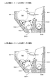
次に、現像部5について説明する。ここで、まず現像部5の構成について図1および図2を参照しつつ説明した後で、現像部5の各部を駆動するための構成について図3および図4を参照しつつ説明する。   Next, the developing unit 5 will be described. Here, first, the configuration of the developing unit 5 will be described with reference to FIGS. 1 and 2, and then the configuration for driving each unit of the developing unit 5 will be described with reference to FIGS. 3 and 4.

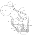
図2は本発明の現像装置の第1実施形態たる現像部を示す図である。現像部5は、図1および図2に示すように、現像ローラー(現像剤担持体ローラー)51と、中間塗布ローラー(第2供給ローラー)52と、アニロックスローラー(第1供給ローラー)53とを有する、いわゆる3ローラー構成を有している。これらのローラー51〜53は、いずれも回転軸が感光体ドラム1の回転軸と平行に配置されながら両端部が一対の側板(図示省略)にそれぞれ回転自在に軸支されている。より詳しくは、各ローラー51〜53はそれぞれ以下のように構成されている。   FIG. 2 is a diagram showing a developing unit according to the first embodiment of the developing device of the present invention. As shown in FIGS. 1 and 2, the developing unit 5 includes a developing roller (developer carrier roller) 51, an intermediate application roller (second supply roller) 52, and an anilox roller (first supply roller) 53. It has a so-called three-roller configuration. Each of these rollers 51 to 53 is pivotally supported by a pair of side plates (not shown) so that both ends thereof are arranged in parallel with the rotation axis of the photosensitive drum 1. More specifically, each of the rollers 51 to 53 is configured as follows.

現像ローラー51は円筒状の部材であり、鉄等金属製の内芯の外周部に、ポリウレタンゴム、シリコンゴム、NBRなどの弾性層を設け、さらに外周部である現像ローラー表層にはPFAチューブや樹脂コーティングされたものである。この現像ローラー51は後述する第1駆動伝達部55(図3)を介して第1駆動モーターM1(図3)に接続されている。そして、装置全体を制御する制御部(図示省略)からの制御指令に応じて第1駆動モーターM1を作動させると、この第1駆動モーターM1からの駆動力により図1及び図2紙面において時計回りD51に回転駆動され、その表面が感光体ドラム1の表面と当接しながら感光体ドラム1と同方向に移動するように回転(以下「ウィズ回転」という)する。また、この現像ローラー51は図示を省略する現像バイアス発生部と電気的に接続されており、適当なタイミングで現像バイアスが印加されるように構成されている。   The developing roller 51 is a cylindrical member, and an elastic layer such as polyurethane rubber, silicon rubber, or NBR is provided on the outer peripheral portion of an inner core made of metal such as iron, and a PFA tube or the like is provided on the developing roller surface layer that is the outer peripheral portion. It is resin-coated. The developing roller 51 is connected to a first drive motor M1 (FIG. 3) via a first drive transmission unit 55 (FIG. 3) described later. When the first drive motor M1 is actuated in response to a control command from a control unit (not shown) that controls the entire apparatus, the drive force from the first drive motor M1 rotates clockwise in FIG. 1 and FIG. The surface is rotated by D51 and rotated so as to move in the same direction as the photosensitive drum 1 while contacting the surface thereof with the surface of the photosensitive drum 1 (hereinafter referred to as “with rotation”). The developing roller 51 is electrically connected to a developing bias generator (not shown) so that the developing bias is applied at an appropriate timing.

また、この現像ローラー51に対して液体現像剤を供給するために中間塗布ローラー52とアニロックスローラー53とが設けられており、アニロックスローラー53から中間塗布ローラー52を介して現像ローラー51へ液体現像剤が供給される。これらのうち中間塗布ローラー52は現像ローラー51と同様に金属製内芯の外周部に弾性層を設けたものであるのに対し、アニロックスローラー53は液体現像剤を担持し易いように表面に微細且つ一様に彫刻された螺旋溝などによる凹部パターンが形成されたローラーである。もちろん、アニロックスローラー53を、現像ローラー51や中間塗布ローラー52と同様に、金属の芯金にウレタン、NBRなどのゴム層を巻き付けたものや、PFAチューブを被せたものなどを用いてもよい。   An intermediate application roller 52 and an anilox roller 53 are provided to supply the liquid developer to the developing roller 51, and the liquid developer is supplied from the anilox roller 53 to the developing roller 51 via the intermediate application roller 52. Is supplied. Among these, the intermediate application roller 52 is provided with an elastic layer on the outer peripheral portion of the metal inner core like the developing roller 51, whereas the anilox roller 53 is fine on the surface so as to easily carry the liquid developer. In addition, the roller has a concave pattern formed by a uniformly engraved spiral groove or the like. Of course, as with the developing roller 51 and the intermediate application roller 52, the anilox roller 53 may be a metal cored bar wrapped with a rubber layer such as urethane or NBR, or a PFA tube covered.

これらのローラーのうち中間塗布ローラー52は第1駆動伝達部55(図3)を介して第1駆動モーターM1からの駆動力を受けて図1及び図2紙面において時計回り回転され、その表面が現像ローラー51の表面と当接しながら現像ローラー51と逆方向に移動するように回転(以下「カウンター回転」という)する。一方、アニロックスローラー53は後述する第2駆動伝達部56(図4)を介して第2駆動モーターM2(図4)に接続されている。そして、制御部からの制御指令に応じて第2駆動モーターM2を作動させると、この第2駆動モーターM2からの駆動力により図1及び図2紙面において反時計回り回転され、その表面が中間塗布ローラー52の表面と当接しながら中間塗布ローラー52と同じ方向に移動する、つまり中間塗布ローラー52に対してウィズ方向に回転する。このように、本実施形態では、いわゆる3ローラー構成により液体現像剤を現像剤容器54から現像ローラー51に供給しているため、液体現像剤がニップを複数回通過することで、液体現像剤を十分に練ることができ、現像ローラー51にて均一な液体現像剤の膜を形成することが可能となる。   Among these rollers, the intermediate application roller 52 receives the driving force from the first driving motor M1 via the first driving transmission portion 55 (FIG. 3) and rotates clockwise in the plane of FIG. 1 and FIG. It rotates (hereinafter referred to as “counter rotation”) so as to move in the opposite direction to the developing roller 51 while being in contact with the surface of the developing roller 51. On the other hand, the anilox roller 53 is connected to a second drive motor M2 (FIG. 4) via a second drive transmission unit 56 (FIG. 4) described later. When the second drive motor M2 is actuated in accordance with a control command from the control unit, the surface is rotated counterclockwise on the paper surface of FIGS. 1 and 2 by the driving force from the second drive motor M2, and the surface thereof is subjected to intermediate coating. It moves in the same direction as the intermediate application roller 52 while contacting the surface of the roller 52, that is, rotates in the width direction with respect to the intermediate application roller 52. Thus, in this embodiment, since the liquid developer is supplied from the developer container 54 to the developing roller 51 by a so-called three-roller configuration, the liquid developer passes through the nip a plurality of times, so that the liquid developer is supplied. It can be sufficiently kneaded, and a uniform liquid developer film can be formed by the developing roller 51.

本実施形態では、現像ローラー51から液体現像剤をクリーニング除去するために、クリーニング部が設けられている。このクリーニング部は、クリーニングローラー511およびローラークリーニングブレード512を有しており、現像ローラー51に対してクリーニングローラー511が当接されるとともに、このクリーニングローラー511に対してローラークリーニングブレード512が当接されており、現像ローラー51のクリーニング処理を行う。より詳しくは、クリーニングローラー511は第1駆動伝達部55(図3)を介して第1駆動モーターM1(図3)からの駆動力を受けて図1及び図2紙面において時計回り回転され、現像ローラー51の表面と当接しながら現像ローラー51に対してカウンター方向に回転し、現像に寄与せずに現像ローラー51に残存する液体現像剤を除去する。また、このクリーニングローラー511の表面にローラークリーニングブレード512が当接して上記液体現像剤を掻き落として除去する。   In the present embodiment, a cleaning unit is provided to remove the liquid developer from the developing roller 51 by cleaning. The cleaning unit includes a cleaning roller 511 and a roller cleaning blade 512. The cleaning roller 511 is in contact with the developing roller 51, and the roller cleaning blade 512 is in contact with the cleaning roller 511. The developing roller 51 is cleaned. More specifically, the cleaning roller 511 receives a driving force from the first drive motor M1 (FIG. 3) via the first drive transmission unit 55 (FIG. 3) and rotates clockwise in FIG. 1 and FIG. Rotating in the counter direction with respect to the developing roller 51 while abutting the surface of the roller 51, the liquid developer remaining on the developing roller 51 without removing the development is removed. Further, a roller cleaning blade 512 comes into contact with the surface of the cleaning roller 511 and scrapes off and removes the liquid developer.

ローラークリーニングブレード512の鉛直方向の下方で、かつ中間塗布ローラー52の鉛直方向の上方で、傾斜部材513が配置されている。この傾斜部材513は、現像ローラー側(図2の左側)の端部が反現像ローラー側(図2の右側)の端部よりも鉛直方向に高くなっており、しかも現像ローラー51から離れるにしたがって鉛直方向の下方に傾斜し、現像剤容器54の回収部541の鉛直方向の上方まで延設されている。そして、現像ローラー側端部がローラークリーニングブレード512の鉛直方向の下方に位置するように傾斜部材513は側板に固定されている。   An inclined member 513 is disposed below the roller cleaning blade 512 in the vertical direction and above the intermediate application roller 52 in the vertical direction. The inclined member 513 has an end portion on the developing roller side (left side in FIG. 2) that is higher in the vertical direction than an end portion on the anti-developing roller side (right side in FIG. 2), and as the distance from the developing roller 51 increases. It inclines downward in the vertical direction and extends to the upper side in the vertical direction of the collection unit 541 of the developer container 54. The inclined member 513 is fixed to the side plate so that the developing roller side end is positioned below the roller cleaning blade 512 in the vertical direction.

また、この傾斜部材513では、幅方向Xの両端側でサイドフェンス(壁部位)5131が鉛直方向の上方に立設されている。しかも、各サイドフェンス5131は傾斜部材513の反現像ローラー側の端部に向かって延設されており、液体現像剤(廃液)を回収部541の鉛直方向の上方に案内する。そして、当該位置から回収された液体現像剤が回収部541に滴下される。したがって、傾斜部材513は、ローラークリーニングブレード512で回収された液体現像剤(廃液)を、全て受け止めて現像剤容器54の回収部541に流入させる。   Further, in the inclined member 513, side fences (wall portions) 5131 are erected on the both ends in the width direction X above the vertical direction. In addition, each side fence 5131 extends toward the end of the inclined member 513 on the side opposite to the developing roller, and guides the liquid developer (waste liquid) upward in the vertical direction of the collection unit 541. Then, the liquid developer recovered from the position is dropped on the recovery unit 541. Therefore, the inclined member 513 receives all of the liquid developer (waste liquid) collected by the roller cleaning blade 512 and causes the liquid developer (waste liquid) to flow into the collecting unit 541 of the developer container 54.

また、中間塗布ローラー52に対してクリーニングブレード521が当接しており、現像に寄与せずに中間塗布ローラー52に残存する液体現像剤を中間塗布ローラー52の表面から掻き落として除去する。   Further, the cleaning blade 521 is in contact with the intermediate application roller 52, and the liquid developer remaining on the intermediate application roller 52 without contributing to the development is scraped off and removed from the surface of the intermediate application roller 52.

このクリーニングブレード521の鉛直方向の下方で、傾斜部材522が配置されている。この傾斜部材522は、傾斜部材513と同様に、中間塗布ローラー側(図2の左側)の端部が反中間塗布ローラー側(図2の右側)の端部よりも鉛直方向に高くなっており、しかも中間塗布ローラー52から離れるにしたがって鉛直方向の下方に傾斜し、現像剤容器54の回収部541の鉛直方向の上方まで延設されている。そして、中間塗布ローラー側端部がクリーニングブレード521の鉛直方向の下方に位置するように傾斜部材522は側板に固定されている。   An inclined member 522 is disposed below the cleaning blade 521 in the vertical direction. Like the inclined member 513, the inclined member 522 has an end on the intermediate application roller side (left side in FIG. 2) that is higher in the vertical direction than an end on the anti-intermediate application roller side (right side in FIG. 2). Moreover, it is inclined downward in the vertical direction as it is away from the intermediate application roller 52, and extends to the upper part of the recovery unit 541 of the developer container 54 in the vertical direction. The inclined member 522 is fixed to the side plate so that the end portion on the intermediate coating roller side is positioned below the cleaning blade 521 in the vertical direction.

また、この傾斜部材522では、幅方向Xの両端側でサイドフェンス(壁部位)5221が鉛直方向の上方に立設されている。しかも、各サイドフェンス5221は傾斜部材522の反中間塗布ローラー側端部に向かって延設されており、液体現像剤(廃液)を回収部541の鉛直方向の上方に案内する。そして、当該位置から回収された液体現像剤が回収部541に滴下される。したがって、傾斜部材522は、ローラークリーニングブレード521で回収された液体現像剤(廃液)を、全て受け止めて現像剤容器54の回収部541に流入させる。   Further, in the inclined member 522, side fences (wall portions) 5221 are erected above the vertical direction at both ends in the width direction X. In addition, each side fence 5221 is extended toward the end of the inclined member 522 facing the anti-intermediate application roller, and guides the liquid developer (waste liquid) in the vertical direction of the collection unit 541. Then, the liquid developer recovered from the position is dropped on the recovery unit 541. Therefore, the inclined member 522 receives all of the liquid developer (waste liquid) collected by the roller cleaning blade 521 and causes the liquid developer (waste liquid) to flow into the collecting unit 541 of the developer container 54.

一方、アニロックスローラー53に対して規制部材531が当接されている。この規制部材531として、金属製あるいは表面に弾性体を被覆して構成した弾性を有する部材を用いることができるが、本実施形態にかかる規制部材531は、アニロックスローラー53の表面に当接するウレタンゴム等からなるゴム部と、該ゴム部を支持する金属等の板で構成されている。そして、規制部材531は、アニロックスローラー53によって担持搬送されてきた液体現像剤の膜厚や量などを規制調整し、現像ローラー51に供給する液体現像剤の量を調整する機能を有している。また、規制部材531により掻き取られた液体現像剤は現像剤容器54の貯留部542に戻される。なお、この貯留部542には撹拌オーガ543が配置されており、後述するように第1駆動伝達部55(図3)を介して第1駆動モーターM1(図3)からの駆動力を受けて図1及び図2紙面において反時計回り回転され、貯留部542内で液体現像剤を撹拌する。   On the other hand, the regulating member 531 is in contact with the anilox roller 53. As the restricting member 531, a metal or a member having elasticity constituted by covering the surface with an elastic body can be used. However, the restricting member 531 according to the present embodiment is a urethane rubber that contacts the surface of the anilox roller 53. Etc., and a plate made of metal or the like that supports the rubber part. The regulating member 531 has a function of regulating and adjusting the film thickness and amount of the liquid developer carried and conveyed by the anilox roller 53 and adjusting the amount of liquid developer supplied to the developing roller 51. . Further, the liquid developer scraped off by the regulating member 531 is returned to the storage portion 542 of the developer container 54. The storage portion 542 is provided with a stirring auger 543, which receives a driving force from the first drive motor M1 (FIG. 3) via the first drive transmission portion 55 (FIG. 3) as will be described later. 1 and FIG. 2 is rotated counterclockwise on the paper surface, and the liquid developer is agitated in the reservoir 542.

現像剤容器54の貯留部542は上記のようにアニロックスローラー53および中間塗布ローラー52を介して現像ローラー51に供給する液体現像剤を貯留する機能を有しており、図2に示すように、貯留部542の底面中央部に設けられた補給口5421から濃度調整された液体現像剤が適宜補給される。そして、貯留部542内では、撹拌オーガ543の回転によって液体現像剤が撹拌されるとともにその軸方向(図1及び図2紙面の垂直方向)に搬送される。本実施形態では、補給口5421を境として撹拌オーガ543の搬送方向が異なったものとなっており、補給口5421から流入した液体現像剤は同図紙面の表側と裏側とに分かれて搬送される。   The storage part 542 of the developer container 54 has a function of storing the liquid developer supplied to the developing roller 51 via the anilox roller 53 and the intermediate application roller 52 as described above. The liquid developer whose concentration is adjusted is appropriately supplied from a supply port 5421 provided at the center of the bottom surface of the reservoir 542. In the storage unit 542, the liquid developer is agitated by the rotation of the agitation auger 543 and conveyed in the axial direction (perpendicular to the paper surface in FIGS. 1 and 2). In this embodiment, the conveyance direction of the agitation auger 543 differs from the supply port 5421 as a boundary, and the liquid developer flowing in from the supply port 5421 is conveyed separately on the front side and the back side of the drawing sheet. .

現像剤容器54では、回収部541と貯留部542とを仕切る壁部材544が軸方向(図1及び図2紙面に対して垂直な方向)に延設されている。この壁部材544の軸方向Xの両端部には、壁部材544の上端を部分的に切り欠いてなる回収口(図示省略)が設けられており、撹拌オーガ543により貯留部542内を搬送される液体現像剤が各回収口を通じてオーバーフローし、回収部541に流動させられるように構成されている。このようにオーバーフロー構造を採用することで、貯留部542内での液体現像剤の液面レベルを一定に保ち、アニロックスローラー53および中間塗布ローラー52を介して現像ローラー51に対して均一に液体現像剤を供給可能となっている。   In the developer container 54, a wall member 544 that partitions the collection unit 541 and the storage unit 542 extends in the axial direction (a direction perpendicular to the plane of FIG. 1 and FIG. 2). At both ends of the wall member 544 in the axial direction X, there are provided recovery ports (not shown) in which the upper end of the wall member 544 is partially cut away, and the inside of the storage unit 542 is conveyed by the stirring auger 543. The liquid developer overflows through each collection port and flows to the collection unit 541. By adopting the overflow structure in this way, the liquid level of the liquid developer in the storage unit 542 is kept constant, and the liquid development is performed uniformly with respect to the developing roller 51 via the anilox roller 53 and the intermediate coating roller 52. The agent can be supplied.

このように回収部541に対しては、貯留部542からオーバーフローしてくる液体現像剤と、クリーニング除去されて回収される液体現像剤とが流入する。そして、この回収部541内には、回収オーガ(回収スクリュー)545が配置されており、後述するように第2駆動伝達部56(図4)を介して第2駆動モーターM2(図4)からの駆動力を受けて図1及び図2紙面において時計回り回転され、回収した液体現像剤を現像ローラー51の回転軸方向と平行な一方向(図2紙面に対して垂直な方向)に搬送し、回収部541の側面に開口された搬送穴(図示省略)から流出させる。   As described above, the liquid developer overflowing from the storage unit 542 and the liquid developer recovered by cleaning and removing flow into the recovery unit 541. A recovery auger (recovery screw) 545 is disposed in the recovery unit 541. From the second drive motor M2 (FIG. 4) via the second drive transmission unit 56 (FIG. 4) as will be described later. 1 and FIG. 2 is rotated clockwise in FIG. 1 and FIG. 2 and the collected liquid developer is conveyed in one direction parallel to the rotation axis direction of the developing roller 51 (perpendicular to FIG. 2). Then, it is caused to flow out from a transport hole (not shown) opened in the side surface of the collection unit 541.

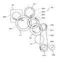
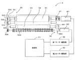
次に、図3および図4に基づき現像部5の各部を上記のように回転させる構成については説明する。図3は第1駆動モーターおよび第1駆動伝達部の構成を示す図であり、図4は第2駆動モーターおよび第2駆動伝達部の構成を示す図である。   Next, a configuration for rotating each part of the developing unit 5 as described above will be described with reference to FIGS. 3 and 4. FIG. 3 is a diagram illustrating the configuration of the first drive motor and the first drive transmission unit, and FIG. 4 is a diagram illustrating the configuration of the second drive motor and the second drive transmission unit.

図3に示すように、第1駆動モーターM1は上記したように現像ローラー51、中間塗布ローラー52および撹拌オーガ543を駆動するための駆動源であり、第1駆動モーターM1で発生する回転駆動力は次の駆動輪列構成を有する第1駆動伝達部55によって現像ローラー51、中間塗布ローラー52および撹拌オーガ543の各回転軸に与えられる。このように、本実施形態では、第1駆動モーターM1および第1駆動伝達部55がそれぞれ本発明の「第1駆動源」および「駆動伝達部」に相当している。   As shown in FIG. 3, the first driving motor M1 is a driving source for driving the developing roller 51, the intermediate application roller 52, and the stirring auger 543 as described above, and the rotational driving force generated by the first driving motor M1. Is provided to the rotation shafts of the developing roller 51, the intermediate application roller 52, and the stirring auger 543 by a first drive transmission unit 55 having the following drive wheel train configuration. Thus, in the present embodiment, the first drive motor M1 and the first drive transmission unit 55 correspond to the “first drive source” and the “drive transmission unit” of the present invention, respectively.

図3における符号550は第1駆動モーターM1の回転軸に取り付けられた出力軸歯車であり、この出力軸歯車550に対して現像駆動歯車551が歯合されている。この現像駆動歯車551は現像ローラー51の回転軸に取り付けられており、出力軸歯車550および現像駆動歯車551を介して第1駆動モーターM1で発生した駆動力が現像ローラー51の回転軸に与えられる。これによって、現像ローラー51は回転駆動される。   Reference numeral 550 in FIG. 3 denotes an output shaft gear attached to the rotation shaft of the first drive motor M1, and the development drive gear 551 is engaged with the output shaft gear 550. The developing drive gear 551 is attached to the rotating shaft of the developing roller 51, and the driving force generated by the first driving motor M1 is applied to the rotating shaft of the developing roller 51 via the output shaft gear 550 and the developing drive gear 551. . As a result, the developing roller 51 is driven to rotate.

現像駆動歯車551は第1アイドル歯車552とも歯合している。この第1アイドル歯車552と同軸に第2アイドル歯車553が取り付けられている。また、この第2アイドル歯車553にクリーニング駆動歯車554が歯合されている。このクリーニング駆動歯車554はクリーニングローラー511の回転軸に取り付けられており、歯車550〜554を介して第1駆動モーターM1で発生した駆動力がクリーニングローラー511の回転軸に与えられる。これによって、クリーニングローラー511は回転駆動される。   The development drive gear 551 is also meshed with the first idle gear 552. A second idle gear 553 is attached coaxially with the first idle gear 552. Further, the cleaning drive gear 554 is engaged with the second idle gear 553. The cleaning drive gear 554 is attached to the rotation shaft of the cleaning roller 511, and the driving force generated by the first drive motor M1 is applied to the rotation shaft of the cleaning roller 511 via the gears 550 to 554. As a result, the cleaning roller 511 is driven to rotate.

第1アイドル歯車552に対しては、中間塗布ローラー52の回転軸に取り付けられた中間塗布駆動歯車555も歯合しており、歯車550〜552、555を介して第1駆動モーターM1で発生した駆動力が中間塗布ローラー52の回転軸に与えられる。これによって、中間塗布ローラー52は現像ローラー51に対してカウンター回転する。なお、本実施形態では、現像駆動歯車551、第1アイドル歯車552および中間塗布駆動歯車555の歯数が次の関係、
(現像駆動歯車551の歯数)>(第1アイドル歯車552の歯数)
(第1アイドル歯車552の歯数)=(中間塗布駆動歯車555の歯数)
を満足するように構成されている。このため、中間塗布ローラー52は現像ローラー51よりも速い回転周速で回転させられる。
An intermediate application drive gear 555 attached to the rotation shaft of the intermediate application roller 52 is also meshed with the first idle gear 552 and is generated by the first drive motor M1 via the gears 550 to 552 and 555. A driving force is applied to the rotation shaft of the intermediate application roller 52. Accordingly, the intermediate application roller 52 rotates counter to the developing roller 51. In this embodiment, the number of teeth of the development drive gear 551, the first idle gear 552, and the intermediate coating drive gear 555 is as follows:
(Number of teeth of development drive gear 551)> (Number of teeth of first idle gear 552)
(Number of teeth of first idle gear 552) = (Number of teeth of intermediate application drive gear 555)
It is configured to satisfy. For this reason, the intermediate application roller 52 is rotated at a rotational peripheral speed faster than the developing roller 51.

中間塗布駆動歯車555は第3アイドル歯車556とも歯合している。この第3アイドル歯車556と同軸に第4アイドル歯車557が取り付けられている。また、撹拌オーガ543の回転軸には、撹拌駆動歯車558が取り付けられている。そして、これら第4アイドル歯車557と撹拌駆動歯車558とはベルト559により連結されている。このため、歯車550〜552、555〜558およびベルト559を介して第1駆動モーターM1で発生した駆動力が撹拌オーガ543の回転軸に与えられる。これによって、撹拌オーガ543は図3紙面における反時計回りに回転する。   The intermediate application drive gear 555 also meshes with the third idle gear 556. A fourth idle gear 557 is attached coaxially with the third idle gear 556. A stirring drive gear 558 is attached to the rotation shaft of the stirring auger 543. The fourth idle gear 557 and the agitation drive gear 558 are connected by a belt 559. For this reason, the driving force generated by the first drive motor M <b> 1 is applied to the rotating shaft of the stirring auger 543 via the gears 550 to 552, 555 to 558 and the belt 559. As a result, the stirring auger 543 rotates counterclockwise on the paper surface of FIG.

図4に示すように、第2駆動モーターM2は上記したようにアニロックスローラー53および回収オーガ545を駆動するための駆動源であり、第2駆動モーターM2で発生する回転駆動力は次の駆動輪列構成を有する第2駆動伝達部56によってアニロックスローラー53および回収オーガ545の各回転軸に与えられる。このように、本実施形態では、第2駆動モーターM2が本発明の「第2駆動源」に相当している。   As shown in FIG. 4, the second drive motor M2 is a drive source for driving the anilox roller 53 and the recovery auger 545 as described above, and the rotational drive force generated by the second drive motor M2 is the next drive wheel. The second drive transmission unit 56 having a row configuration is given to each rotation shaft of the anilox roller 53 and the collection auger 545. Thus, in the present embodiment, the second drive motor M2 corresponds to the “second drive source” of the present invention.

図4における符号560は第2駆動モーターM2の回転軸に取り付けられた出力軸歯車であり、この出力軸歯車560に対してアニロックス駆動歯車561および第5アイドル歯車562が歯合されている。これらのうちアニロックス駆動歯車561はアニロックスローラー53の回転軸に取り付けられており、歯車560、561を介して第2駆動モーターM2で発生した駆動力がアニロックスローラー53の回転軸に与えられる。これによって、アニロックスローラー53は回転駆動される。   Reference numeral 560 in FIG. 4 is an output shaft gear attached to the rotation shaft of the second drive motor M2, and the anilox drive gear 561 and the fifth idle gear 562 are engaged with the output shaft gear 560. Among these, the anilox drive gear 561 is attached to the rotation shaft of the anilox roller 53, and the driving force generated by the second drive motor M <b> 2 is applied to the rotation shaft of the anilox roller 53 via the gears 560 and 561. As a result, the anilox roller 53 is driven to rotate.

また、出力軸歯車560は第5アイドル歯車562とも歯合し、さらに第5アイドル歯車562に対して回収駆動歯車563が歯合する。この回収駆動歯車563は回収オーガ545の回転軸に取り付けられており、歯車560、562、563を介して第2駆動モーターM2で発生した駆動力が回収オーガ545の回転軸に与えられる。これによって、回収オーガ545は回転駆動される。   Further, the output shaft gear 560 meshes with the fifth idle gear 562, and the recovery drive gear 563 meshes with the fifth idle gear 562. The collection drive gear 563 is attached to the rotation shaft of the collection auger 545, and the driving force generated by the second drive motor M2 is applied to the rotation shaft of the collection auger 545 via the gears 560, 562, and 563. As a result, the collection auger 545 is driven to rotate.

以上のように、第1実施形態では、第1駆動モーターM1で発生する駆動力を第1駆動伝達部55によって現像ローラー51および中間塗布ローラー52に与えて回転させるように構成しているため、次の作用効果が得られる。すなわち、駆動モーターM1の回転成分は周期的に変動し、また第1駆動伝達部55を構成する歯車のかみ合い周期変動が存在している。このため、現像ローラー51の回転周速V51および中間塗布ローラー52の回転周速V52には、例えば図5に示すように、周期変動が含まれている。例えば同図(a)は回転周速V51と回転周速V52との位相差が180゜のときの回転周速差を示し、また同図(b)が回転周速V51と回転周速V52との位相差が0゜のときの回転周速差を示している。このように回転周速差(=V52−V51)は位相差により変動し、位相差に対する回転周速差の変動率をまとめると、図6に示すグラフとなる。この図6から明らかなように、位相差が小さくなるにしたがって現像ローラー51と中間塗布ローラー52との回転周速差が少なく、中間塗布ローラー52から現像ローラー51に供給される液体現像剤の量を安定化することが可能となる。この点に関し、第1実施形態では、現像ローラー51および中間塗布ローラー52はともに第1駆動モーターM1を駆動源とし、しかも同一の第1駆動伝達部55を介して第1駆動モーターM1からの駆動力を受けているため、第1駆動モーターM1の回転成分の変動及び歯車のかみ合い周期変動の位相が揃うため、現像ローラー51と中間塗布ローラー52との回転周速差が小さくなり、現像ローラー51への液体現像剤の供給を安定化させることができる。   As described above, in the first embodiment, the driving force generated by the first drive motor M1 is applied to the developing roller 51 and the intermediate application roller 52 by the first drive transmission unit 55 so as to be rotated. The following effects can be obtained. That is, the rotational component of the drive motor M1 varies periodically, and there is a meshing cycle variation of the gears constituting the first drive transmission unit 55. For this reason, the rotational peripheral speed V51 of the developing roller 51 and the rotational peripheral speed V52 of the intermediate application roller 52 include periodic fluctuations as shown in FIG. 5, for example. For example, FIG. 4A shows the rotational peripheral speed difference when the phase difference between the rotational peripheral speed V51 and the rotational peripheral speed V52 is 180 °, and FIG. 4B shows the rotational peripheral speed V51 and the rotational peripheral speed V52. The rotational peripheral speed difference is shown when the phase difference is 0 °. As described above, the rotational peripheral speed difference (= V52−V51) varies depending on the phase difference, and the fluctuation rates of the rotational peripheral speed difference with respect to the phase difference are summarized as a graph shown in FIG. As is clear from FIG. 6, the difference in rotational peripheral speed between the developing roller 51 and the intermediate coating roller 52 decreases as the phase difference decreases, and the amount of liquid developer supplied from the intermediate coating roller 52 to the developing roller 51 Can be stabilized. In this regard, in the first embodiment, both the developing roller 51 and the intermediate application roller 52 use the first drive motor M1 as a drive source and are driven from the first drive motor M1 via the same first drive transmission unit 55. Since the phase of the fluctuation of the rotational component of the first drive motor M1 and the change of the gear meshing cycle are aligned because the force is received, the rotational peripheral speed difference between the developing roller 51 and the intermediate coating roller 52 becomes small, and the developing roller 51 It is possible to stabilize the supply of the liquid developer.

また、上記第1実施形態では、中間塗布ローラー52は現像ローラー51と逆方向に現像ローラー51よりも速い回転周速で回転するように第1駆動伝達部55を構成する歯車551、552、555の歯数が設定されている。このため、上記のように中間塗布ローラー52に形成される液体現像剤層を伸張することなく、現像ローラー51に供給することができ、均された平滑な液体現像剤の層を現像ローラー51の表面に供給することができる。なお、中間塗布ローラー52が現像ローラー51の回転周速と同じ回転周速で回転するように構成してもよく、この場合も同様の作用効果が得られる。   In the first embodiment, the intermediate application roller 52 rotates in the reverse direction to the developing roller 51 at a rotational peripheral speed faster than that of the developing roller 51, and the gears 551, 552, and 555 constituting the first drive transmission unit 55. The number of teeth is set. For this reason, the liquid developer layer formed on the intermediate application roller 52 as described above can be supplied to the developing roller 51 without stretching, and the leveled smooth liquid developer layer can be supplied to the developing roller 51. Can be supplied to the surface. The intermediate application roller 52 may be configured to rotate at the same rotational peripheral speed as that of the developing roller 51. In this case, the same effect can be obtained.

また、第1実施形態では、現像ローラー51および中間塗布ローラー52を駆動する駆動源(第1駆動モーターM1)とは別に第2駆動モーターM2を設け、制御部からの指令に応じて第2駆動モーターM2の回転数を制御してアニロックスローラー53の回転周速を調整している。このため、中間塗布ローラー52およびアニロックスローラー53の間で回転周速差を付けることができ、その回転周速差に応じて液体現像剤の供給量、つまり中間塗布ローラー52に形成される液体現像剤層の厚みを調整することができる。このように、本実施形態では、制御部が本発明の「調整部」として機能している。   In the first embodiment, the second drive motor M2 is provided separately from the drive source (first drive motor M1) for driving the developing roller 51 and the intermediate application roller 52, and the second drive is performed according to a command from the control unit. The rotational speed of the anilox roller 53 is adjusted by controlling the rotational speed of the motor M2. Therefore, a difference in rotational peripheral speed can be provided between the intermediate application roller 52 and the anilox roller 53, and the amount of liquid developer supplied, that is, liquid development formed on the intermediate application roller 52 in accordance with the rotational peripheral speed difference. The thickness of the agent layer can be adjusted. Thus, in this embodiment, the control unit functions as the “adjusting unit” of the present invention.

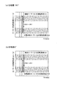
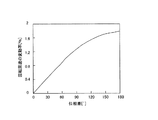
また、制御部からの指令によりアニロックスローラー53が中間塗布ローラー52よりも遅い回転周速で中間塗布ローラー52と同じ方向に移動する、つまり中間塗布ローラー52に対してウィズ方向に回転することで、回転精度を向上させることができる。この理由を図7および図8を参照しつつ説明する。   Further, the anilox roller 53 is moved in the same direction as the intermediate application roller 52 at a rotational peripheral speed slower than that of the intermediate application roller 52 by a command from the control unit, that is, by rotating in the width direction with respect to the intermediate application roller 52, Rotational accuracy can be improved. The reason for this will be described with reference to FIGS.

図7は、中間塗布ローラーが現像ローラーおよびアニロックスローラーから受ける力を解析した図であり、同図(a)はアニロックスローラーの回転周速を中間塗布ローラーの回転周速よりも速くした場合を示し、同図(b)はアニロックスローラーの回転周速を中間塗布ローラーの回転周速よりも遅くした場合を示している。また、図8は中間塗布ローラーの回転周速の変動率を示すグラフであり、同図(a)はアニロックスローラーの回転周速を中間塗布ローラーの回転周速よりも速くした場合を示し、同図(b)はアニロックスローラーの回転周速を中間塗布ローラーの回転周速よりも遅くした場合を示している。第1実施形態にかかる現像部5では、中間塗布ローラー52は現像ローラー51から接線力(摩擦力)F21を受けるとともに、アニロックスローラー53から接線力(摩擦力)F23を受けるが、それらの接線力F21、F23の向きは中間塗布ローラー52の回転周速V52とアニロックスローラー53の回転周速V53との大小関係により異なってくる。すなわち、アニロックスローラー53の回転周速V53を中間塗布ローラー52の回転周速V52よりも速くした場合、図7(a)に示すように、接線力F21、F23の向きは互いに逆方向となり、歯車が噛み合う方向が定まらず、噛み合いが不安定となる。その結果、歯車のバックラッシ分の回転変動が発生して中間塗布ローラー52の回転周速V52の変動が大きくなる(図8(a)参照)。   FIG. 7 is a diagram in which the force applied to the intermediate coating roller from the developing roller and the anilox roller is analyzed. FIG. 7A shows the case where the rotational peripheral speed of the anilox roller is higher than the rotational peripheral speed of the intermediate coating roller. FIG. 4B shows a case where the rotational peripheral speed of the anilox roller is made slower than the rotational peripheral speed of the intermediate application roller. FIG. 8 is a graph showing the fluctuation rate of the rotational peripheral speed of the intermediate coating roller. FIG. 8A shows the case where the rotational peripheral speed of the anilox roller is made faster than the rotational peripheral speed of the intermediate coating roller. FIG. (B) shows a case where the rotational peripheral speed of the anilox roller is made slower than the rotational peripheral speed of the intermediate application roller. In the developing unit 5 according to the first embodiment, the intermediate coating roller 52 receives a tangential force (friction force) F21 from the developing roller 51 and also receives a tangential force (friction force) F23 from the anilox roller 53. The directions of F21 and F23 differ depending on the magnitude relationship between the rotational peripheral speed V52 of the intermediate application roller 52 and the rotational peripheral speed V53 of the anilox roller 53. That is, when the rotational peripheral speed V53 of the anilox roller 53 is higher than the rotational peripheral speed V52 of the intermediate application roller 52, the directions of the tangential forces F21 and F23 are opposite to each other as shown in FIG. The meshing direction is not determined, and the meshing becomes unstable. As a result, the rotational fluctuation corresponding to the backlash of the gear occurs, and the fluctuation of the rotational peripheral speed V52 of the intermediate application roller 52 becomes large (see FIG. 8A).

これに対し、アニロックスローラー53の回転周速V53を中間塗布ローラー52の回転周速V52よりも遅くした場合、図7(b)に示すように、接線力F21、F23の向きは同方向となり、中間塗布ローラー52が回転される方向に歯車が安定して噛み合い、予圧を与えることができる。その結果、図8(b)に示すように中間塗布ローラー52の回転周速V52の変動は小さく、中間塗布ローラー52を高精度に回転させることができる。   On the other hand, when the rotational peripheral speed V53 of the anilox roller 53 is made slower than the rotational peripheral speed V52 of the intermediate application roller 52, the directions of the tangential forces F21 and F23 are the same as shown in FIG. The gears can stably mesh in the direction in which the intermediate application roller 52 is rotated, and a preload can be applied. As a result, as shown in FIG. 8B, the fluctuation of the rotational peripheral speed V52 of the intermediate application roller 52 is small, and the intermediate application roller 52 can be rotated with high accuracy.

また、第1実施形態では、第1駆動モーターM1で発生した駆動力を撹拌オーガ543の回転軸に与えて撹拌オーガ543を回転させているため、次のような作用効果が得られる。上記現像部5では、2つの駆動モーターM1、M2が設けられているため、撹拌オーガ543を回転させるための駆動源として駆動モーターM1、M2の一方を用いることができる。ここで、第1実施形態のように、第1駆動モーターM1を撹拌オーガ543の駆動源として用いた場合、現像ローラー51と同輪列で駆動されるため、撹拌オーガ543の回転数が一定となる。そのため、図9(a)に示すように、現像剤容器54の貯留部542に貯留される液体現像剤の液面を安定化することができ、アニロックスローラー53により貯留部542から汲み上げられる液体現像剤の量を安定化することができる。その結果、現像ローラー51に塗布される液体現像剤の量は一定となり、画像濃度ムラを発生させることなく、優れた画像品質で現像することができる。   In the first embodiment, since the stirring auger 543 is rotated by applying the driving force generated by the first drive motor M1 to the rotating shaft of the stirring auger 543, the following effects can be obtained. Since the developing unit 5 includes two drive motors M1 and M2, one of the drive motors M1 and M2 can be used as a drive source for rotating the stirring auger 543. Here, as in the first embodiment, when the first drive motor M1 is used as a drive source for the stirring auger 543, it is driven in the same wheel train as the developing roller 51. Become. Therefore, as shown in FIG. 9A, the liquid level of the liquid developer stored in the storage unit 542 of the developer container 54 can be stabilized, and the liquid development pumped up from the storage unit 542 by the anilox roller 53. The amount of agent can be stabilized. As a result, the amount of liquid developer applied to the developing roller 51 is constant, and development can be performed with excellent image quality without causing uneven image density.

これに対し、アニロックスローラー53の駆動源たる第2駆動モーターM2を撹拌オーガ543の駆動源として用いると、図9(b)に示すように、現像剤容器54の貯留部542に貯留される液体現像剤の液面が暴れてしまうことがある。というのも、アニロックスローラー53の回転数は必要な塗布量に応じて随時変更されるため、それに伴って撹拌オーガ543の回転数も変更されるからである。このため、貯留部542では、液体現像剤の液面レベルが大きく変動してしまい、アニロックスローラー53による液体現像剤の汲み上げ量がばらつくことがある。その結果、現像ローラー51に塗布される液体現像剤の量が変動し、画像濃度ムラは発生することがある。   On the other hand, when the second drive motor M2 that is the drive source of the anilox roller 53 is used as the drive source of the stirring auger 543, the liquid stored in the storage portion 542 of the developer container 54 as shown in FIG. The liquid level of the developer may be violated. This is because the rotation speed of the anilox roller 53 is changed at any time according to the required application amount, and accordingly, the rotation speed of the stirring auger 543 is also changed. For this reason, the liquid level of the liquid developer largely fluctuates in the storage unit 542, and the pumping amount of the liquid developer by the anilox roller 53 may vary. As a result, the amount of liquid developer applied to the developing roller 51 varies, and image density unevenness may occur.

このように、現像ローラー51の駆動源たる第1駆動モーターM1で発生する駆動力を第1駆動伝達部55により撹拌オーガ543に与えて回転させるように構成した第1実施形態によれば、液体現像剤の塗布量を安定化させて画像品質の向上を図ることができる。   As described above, according to the first embodiment in which the driving force generated by the first driving motor M1 that is the driving source of the developing roller 51 is applied to the stirring auger 543 by the first driving transmission unit 55 and rotated. Image quality can be improved by stabilizing the coating amount of the developer.

さらに、上記第1実施形態では、回収オーガ545の駆動源として第2駆動モーターM2を用いているため、次の作用効果が得られる。回収オーガ545は現像剤容器54の回収部541に配設されており、回収部541に回収された液体現像剤(回収液)を搬送して回収部541から回収液が溢れ出すのを防止する機能を担っている。この回収部541に回収される液体現像剤の量はアニロックスローラー53により汲み上げられる量に比例して増減する。このため、アニロックスローラー53により汲み上げられる最大量に対応した回転数で回収オーガ545を常時回転させておくと、回収部541から回収液の溢れを未然に防止することができる。しかしながら、高回転数を維持すると、軸端のシール(図示省略)の磨耗・劣化が進行し易くなる。そこで、本実施形態では、アニロックスローラー53により汲み上げられる量がアニロックスローラー53の回転数に比例することに着目し、図4に示すように、アニロックスローラー53の駆動源たる第2駆動モーターM2に対し、第2駆動伝達部56を介して回収オーガ545を接続している。つまり、アニロックスローラー53の回転数と比例して回収オーガ545の回転数が増減するように構成している。これによって、アニロックスローラー53の回転数を増加させて多くの液体現像剤を使用するときには回収オーガ545の回転数を高めて回収部541からの回収液の溢れを防止する一方、アニロックスローラー53の回転数を減少させて液体現像剤の使用量を抑えたときには回収オーガ545の回転数も低下させてシールの劣化を防止することができる。このように、液体現像剤の使用状況に応じて回収オーガ545の回転数を制御することで、回収液の溢れ防止とシール劣化の防止とを達成することができる。   Furthermore, in the first embodiment, since the second drive motor M2 is used as a drive source for the collection auger 545, the following operational effects can be obtained. The collection auger 545 is disposed in the collection unit 541 of the developer container 54, and transports the liquid developer (collected liquid) collected in the collection unit 541 to prevent the collected liquid from overflowing from the collection unit 541. It has a function. The amount of liquid developer recovered by the recovery unit 541 increases or decreases in proportion to the amount pumped up by the anilox roller 53. For this reason, if the collection auger 545 is always rotated at a rotation speed corresponding to the maximum amount pumped up by the anilox roller 53, overflow of the collection liquid from the collection unit 541 can be prevented in advance. However, if the high rotational speed is maintained, wear and deterioration of the shaft end seal (not shown) is likely to proceed. Therefore, in this embodiment, paying attention to the fact that the amount pumped up by the anilox roller 53 is proportional to the rotation speed of the anilox roller 53, as shown in FIG. 4, the second drive motor M2 that is the drive source of the anilox roller 53 is used. The recovery auger 545 is connected via the second drive transmission unit 56. That is, the collection auger 545 is configured to increase or decrease in proportion to the rotation speed of the anilox roller 53. As a result, when the number of rotations of the anilox roller 53 is increased and a large amount of liquid developer is used, the number of rotations of the collection auger 545 is increased to prevent overflow of the collected liquid from the collection unit 541, while the rotation of the anilox roller 53 is performed. When the number of liquid developers is reduced by decreasing the number, the number of rotations of the recovery auger 545 can also be reduced to prevent seal deterioration. Thus, by controlling the rotation speed of the collection auger 545 according to the usage state of the liquid developer, it is possible to achieve prevention of overflow of the collected liquid and prevention of seal deterioration.

なお、本発明は上記した実施形態に限定されるものではなく、その趣旨を逸脱しない限りにおいて上述したもの以外に種々の変更を行うことが可能である。例えば、第1駆動伝達部55および第2駆動伝達部56の構成は上記第1実施形態で採用された構成に限定されるものではなく、例えば図10に示すように、第1駆動モーターM1の回転軸がカップリング(接続部材)57を介して現像ローラー51の回転軸の一方端に直結してもよい(第2実施形態)。この第2実施形態では、カップリング57は、第1駆動モーターM1の回転軸と同軸に配設された第1の駆動伝達部材(図示省略)及び現像ローラー51の回転軸と同軸に配設されて第1の駆動伝達部材と接続された第2の駆動伝達部材(図示省略)を有している。したがって、歯車550、551を介して第1駆動モーターM1と現像ローラー51とを接続した第1実施形態に比べて回転精度を高めることができ、好適である。また、このようにダイレクトドライブ方式を採用した第2実施形態では、例えば図10および図11に示すように、現像ローラー51の回転軸の他方端に歯車551を取り付けるとともに、第1実施形態と同様に、歯車552〜558およびベルト559を設け、現像ローラー51の回転とともに、中間塗布ローラー52および撹拌オーガ543が回転するように構成してもよい。なお、図10中の符号91は画像形成装置全体を制御する制御部であり、符号92、93は、制御部91からの制御指令に基づき、それぞれ駆動モーターM1、M2を駆動させる第1モーター駆動部および第2モーター駆動部であり、制御部91が本発明の「調整部」として機能する。   The present invention is not limited to the above-described embodiment, and various modifications other than those described above can be made without departing from the spirit of the present invention. For example, the configuration of the first drive transmission unit 55 and the second drive transmission unit 56 is not limited to the configuration adopted in the first embodiment. For example, as shown in FIG. The rotating shaft may be directly connected to one end of the rotating shaft of the developing roller 51 via a coupling (connecting member) 57 (second embodiment). In the second embodiment, the coupling 57 is disposed coaxially with the first drive transmission member (not shown) disposed coaxially with the rotational shaft of the first drive motor M1 and the rotational shaft of the developing roller 51. And a second drive transmission member (not shown) connected to the first drive transmission member. Therefore, the rotational accuracy can be improved as compared with the first embodiment in which the first drive motor M1 and the developing roller 51 are connected via the gears 550 and 551, which is preferable. In the second embodiment employing the direct drive system as described above, for example, as shown in FIGS. 10 and 11, a gear 551 is attached to the other end of the rotation shaft of the developing roller 51 and the same as in the first embodiment. Further, gears 552 to 558 and a belt 559 may be provided, and the intermediate application roller 52 and the stirring auger 543 may be configured to rotate as the developing roller 51 rotates. Note that reference numeral 91 in FIG. 10 denotes a control unit that controls the entire image forming apparatus, and reference numerals 92 and 93 denote first motor drives that drive the drive motors M1 and M2, respectively, based on a control command from the control unit 91. And the second motor drive unit, and the control unit 91 functions as the “adjustment unit” of the present invention.

また、第1駆動伝達部55を構成する歯車数を低減するために、第1駆動モーターM1としてギア内蔵モーターを用いてもよい。   In order to reduce the number of gears constituting the first drive transmission unit 55, a gear built-in motor may be used as the first drive motor M1.

さらに、上記実施形態では、いわゆる下部転写構造を有する画像形成装置に対して本発明を適用した場合について説明した。しかしながら、本発明の適用対象はこれに限定されるものではなく、例えば感光体ドラム1の回転中心を通る仮想水平面HPの鉛直方向の上方で、感光体ドラム1に担持される像を転写する、いわゆる上部転写構造を有する画像形成装置に対しても本発明を適用することができる。   Furthermore, in the above embodiment, the case where the present invention is applied to an image forming apparatus having a so-called lower transfer structure has been described. However, the application target of the present invention is not limited to this. For example, an image carried on the photosensitive drum 1 is transferred above the virtual horizontal plane HP passing through the rotation center of the photosensitive drum 1. The present invention can also be applied to an image forming apparatus having a so-called upper transfer structure.

1…感光体ドラム(潜像担持体)、 5…現像部(現像装置)、 51…現像ローラー(現像剤担持体ローラー)、 52…中間塗布ローラー(第2供給ローラー)、 53…アニロックスローラー(第1供給ローラー)、 54…現像剤容器、 57…カップリング(駆動伝達部)、 91…制御部、 511…クリーニングローラー、 512…ローラークリーニングブレード、 541…回収部、 542…貯留部、 543…撹拌オーガ(撹拌部材)、 545…回収オーガ(搬送部材)、 M1…第1駆動モーター(第1駆動源)、 M2…第2駆動モーター(第2駆動源)、 V51…(現像ローラーの)回転周速、 V52…(中間塗布ローラーの)回転周速、 V53…(アニロックスローラーの)回転周速   DESCRIPTION OF SYMBOLS 1 ... Photosensitive drum (latent image carrier), 5 ... Developing part (developing device), 51 ... Developing roller (developer carrier roller), 52 ... Intermediate application roller (second supply roller), 53 ... Anilox roller ( (First supply roller), 54 ... developer container, 57 ... coupling (drive transmission unit), 91 ... control unit, 511 ... cleaning roller, 512 ... roller cleaning blade, 541 ... collection unit, 542 ... storage unit, 543 ... Stirring auger (stirring member), 545 ... Recovery auger (conveying member), M1 ... First driving motor (first driving source), M2 ... Second driving motor (second driving source), V51 ... (Developing roller) rotation Peripheral speed, V52 ... Rotational peripheral speed (of intermediate coating roller), V53 ... Rotational peripheral speed (of anilox roller)

Claims (8)

トナーおよびキャリア液を含む液体現像剤を貯留する貯留部と、
回転して前記貯留部に貯留される液体現像剤を担持する第1供給ローラーと、
前記第1供給ローラーと当接するとともに回転して前記第1供給ローラーから液体現像剤が供給される第2供給ローラーと、
前記第2供給ローラーと当接するとともに回転して前記第2供給ローラーから供給される液体現像剤を担持する現像剤担持体ローラーと、
前記現像剤担持体ローラーと前記第2供給ローラーを駆動させる第1駆動源と、
前記第1供給ローラーを駆動させる第2駆動源と、
を備えることを特徴とする現像装置。
A reservoir for storing a liquid developer containing toner and carrier liquid;
A first supply roller that carries a liquid developer that rotates and is stored in the storage unit;
A second supply roller that contacts and rotates with the first supply roller and is supplied with the liquid developer from the first supply roller;
A developer carrier roller that abuts on the second supply roller and rotates to carry the liquid developer supplied from the second supply roller;
A first drive source for driving the developer carrier roller and the second supply roller;
A second drive source for driving the first supply roller;
A developing device comprising:
潜像が形成される潜像担持体と、
トナーおよびキャリア液を含む液体現像剤を貯留する貯留部、回転して前記貯留部に貯留される液体現像剤を担持する第1供給ローラー、前記第1供給ローラーと当接するとともに回転して前記第1供給ローラーから液体現像剤が供給される第2供給ローラー、及び前記第2供給ローラーと当接するとともに回転して前記第2供給ローラーから供給される液体現像剤を担持する現像剤担持体ローラーを有し、前記潜像担持体に形成された前記潜像を現像する現像部と、
前記現像剤担持体ローラーと前記第2供給ローラーを駆動させる第1駆動源と、
前記第1供給ローラーを駆動させる第2駆動源と、
を備えることを特徴とする画像形成装置。
A latent image carrier on which a latent image is formed;
A storage section for storing a liquid developer containing toner and a carrier liquid; a first supply roller that rotates and carries the liquid developer stored in the storage section; A second supply roller to which a liquid developer is supplied from one supply roller, and a developer carrier roller that contacts the second supply roller and rotates to carry the liquid developer supplied from the second supply roller A developing unit for developing the latent image formed on the latent image carrier;
A first drive source for driving the developer carrier roller and the second supply roller;
A second drive source for driving the first supply roller;
An image forming apparatus comprising:
前記第1駆動源で発生する駆動力を前記現像剤担持体ローラーおよび前記第2供給ローラーに伝達し、前記現像剤担持体ローラーを回転させるとともに、前記現像剤担持体ローラーの回転方向と同じ方向に回転させ、かつ前記現像剤担持体ローラーの回転周速と同じ、もしくは現像剤担持体ローラーの回転周速よりも速く前記第2供給ローラーを回転させる駆動伝達部を備える請求項2に記載の画像形成装置。   The driving force generated by the first drive source is transmitted to the developer carrier roller and the second supply roller to rotate the developer carrier roller, and the same direction as the rotation direction of the developer carrier roller And a drive transmission unit that rotates the second supply roller at a speed equal to or faster than a rotational peripheral speed of the developer carrier roller. Image forming apparatus. 前記駆動伝達部は、前記第1駆動源の回転軸と同軸に配設された第1の駆動伝達部材、及び前記現像剤担持体ローラーの回転軸と同軸に配設されて前記第1の駆動伝達部材と接続された第2の駆動伝達部材を有する請求項2または3に記載の画像形成装置。   The drive transmission unit is disposed on the same axis as the first drive transmission member disposed coaxially with the rotation axis of the first drive source, and the rotation axis of the developer carrier roller, and the first drive. The image forming apparatus according to claim 2, further comprising a second drive transmission member connected to the transmission member. 前記第2駆動源で発生された駆動力により、前記第1供給ローラーは前記第2供給ローラーの回転方向と逆方向に回転し、かつ前記第2供給ローラーの回転周速よりも遅く回転する請求項2ないし4のいずれか一項に記載の画像形成装置。   The first supply roller rotates in a direction opposite to the rotation direction of the second supply roller by the driving force generated by the second drive source, and rotates slower than the rotational peripheral speed of the second supply roller. Item 5. The image forming apparatus according to any one of Items 2 to 4. 前記第1供給ローラーの回転周速を調整する調整部を備える請求項2ないし5のいずれか一項に記載の画像形成装置。   The image forming apparatus according to claim 2, further comprising an adjustment unit that adjusts a rotational peripheral speed of the first supply roller. 前記貯留部に配設され、前記第1駆動源で発生する駆動力を受けて回転して前記貯留部に貯留される液体現像剤を撹拌する撹拌部材を備える請求項2ないし6のいずれか一項に記載の画像形成装置。   7. The agitation member according to claim 2, further comprising: an agitation member that is disposed in the storage unit and rotates by receiving a driving force generated by the first drive source to stir the liquid developer stored in the storage unit. The image forming apparatus described in the item. 前記現像剤担持体ローラーをクリーニングして液体現像剤を回収するクリーニング部と、
前記クリーニング部で回収された液体現像剤を貯留する回収部と、
前記回収部に配設され、前記第2駆動源で発生する駆動力を受けて回転して前記回収部に回収された液体現像剤を搬送する搬送部材と、
を備える請求項2ないし7のいずれか一項に記載の画像形成装置。
A cleaning unit for cleaning the developer carrying roller and recovering the liquid developer;
A collection unit for storing the liquid developer collected by the cleaning unit;
A conveying member that is disposed in the collecting unit and that rotates by receiving a driving force generated by the second driving source and conveys the liquid developer collected in the collecting unit;
An image forming apparatus according to any one of claims 2 to 7.
JP2011059074A 2011-03-17 2011-03-17 Developing device and image forming device Withdrawn JP2012194426A (en)

Priority Applications (2)

Application Number Priority Date Filing Date Title
JP2011059074A JP2012194426A (en) 2011-03-17 2011-03-17 Developing device and image forming device
US13/397,267 US20120237266A1 (en) 2011-03-17 2012-02-15 Developing Apparatus and Image Forming Apparatus

Applications Claiming Priority (1)

Application Number Priority Date Filing Date Title
JP2011059074A JP2012194426A (en) 2011-03-17 2011-03-17 Developing device and image forming device

Publications (1)

Publication Number Publication Date
JP2012194426A true JP2012194426A (en) 2012-10-11

Family

ID=46828570

Family Applications (1)

Application Number Title Priority Date Filing Date
JP2011059074A Withdrawn JP2012194426A (en) 2011-03-17 2011-03-17 Developing device and image forming device

Country Status (2)

Country Link
US (1) US20120237266A1 (en)
JP (1) JP2012194426A (en)

Cited By (1)

* Cited by examiner, † Cited by third party
Publication number Priority date Publication date Assignee Title
JP2019168486A (en) * 2018-03-22 2019-10-03 富士ゼロックス株式会社 Image forming apparatus

Families Citing this family (5)

* Cited by examiner, † Cited by third party
Publication number Priority date Publication date Assignee Title
US20120207508A1 (en) * 2011-02-15 2012-08-16 Seiko Epson Corporation Image Forming Apparatus and Image Forming Method
JP6242201B2 (en) 2012-12-14 2017-12-06 キヤノン株式会社 Process cartridge and image forming apparatus
US9696684B2 (en) 2012-12-14 2017-07-04 Canon Kabushiki Kaisha Process cartridge and image forming apparatus
JP6612636B2 (en) * 2016-02-01 2019-11-27 株式会社ミヤコシ Wet development equipment
JP7131057B2 (en) * 2018-04-27 2022-09-06 コニカミノルタ株式会社 Developing device and image forming device

Family Cites Families (15)

* Cited by examiner, † Cited by third party
Publication number Priority date Publication date Assignee Title
JPH11265122A (en) * 1998-01-08 1999-09-28 Ricoh Co Ltd Image forming device
JP4074737B2 (en) * 1999-04-23 2008-04-09 株式会社リコー Liquid image forming apparatus and program recording medium
US6868246B2 (en) * 2001-11-20 2005-03-15 Ricoh Company, Ltd. Developing liquid coating device, developing device including the same and image forming apparatus including the developing device
EP2866097A1 (en) * 2005-09-09 2015-04-29 Xeikon IP BV High speed electrographic printing
JP4382031B2 (en) * 2005-11-25 2009-12-09 京セラミタ株式会社 Liquid developing apparatus and wet image forming apparatus provided with the same
JP2007148243A (en) * 2005-11-30 2007-06-14 Kyocera Mita Corp Liquid developing device and image forming apparatus on which the same is mounted
JP2010107538A (en) * 2008-10-28 2010-05-13 Seiko Epson Corp Developing device, image forming apparatus, and developing method
JP5287163B2 (en) * 2008-11-18 2013-09-11 コニカミノルタ株式会社 Image forming apparatus and image forming method
JP2010204469A (en) * 2009-03-04 2010-09-16 Seiko Epson Corp Image forming method and image forming apparatus
JP2011033856A (en) * 2009-08-03 2011-02-17 Seiko Epson Corp Image forming apparatus and image forming method
JP2012088498A (en) * 2010-10-19 2012-05-10 Konica Minolta Holdings Inc Image forming apparatus
JP2012108219A (en) * 2010-11-16 2012-06-07 Seiko Epson Corp Image forming apparatus
JP2012145808A (en) * 2011-01-13 2012-08-02 Seiko Epson Corp Image forming device and image forming method
JP2012220600A (en) * 2011-04-06 2012-11-12 Seiko Epson Corp Developing device and image forming device
JP5696597B2 (en) * 2011-06-17 2015-04-08 コニカミノルタ株式会社 Wet image forming device

Cited By (1)

* Cited by examiner, † Cited by third party
Publication number Priority date Publication date Assignee Title
JP2019168486A (en) * 2018-03-22 2019-10-03 富士ゼロックス株式会社 Image forming apparatus

Also Published As

Publication number Publication date
US20120237266A1 (en) 2012-09-20

Similar Documents

Publication Publication Date Title
JP5622783B2 (en) Image forming apparatus
JP5728970B2 (en) Developer amount detecting device, developing device, process unit, and image forming apparatus
JP2012194426A (en) Developing device and image forming device
JP2013171104A (en) Image forming apparatus
JP2012242611A (en) Recovery device and image forming apparatus
JP4816881B2 (en) Image forming apparatus and image forming method
JP2006053468A (en) Image forming apparatus
JP2012198497A (en) Image forming device
JP5196678B2 (en) Cleaning device and image forming apparatus
JP5423346B2 (en) Image forming apparatus
JP5158473B2 (en) Developing device and image forming apparatus
JP5300002B2 (en) Toner transport mechanism, developing device including the toner transport mechanism, and image forming apparatus
JP2012103547A (en) Image forming apparatus
JP2012230187A (en) Collecting device and image forming device
JP2008292700A (en) Image forming apparatus
JP2008026521A (en) Image forming apparatus
JP6618740B2 (en) Conveying device, developing device, and image forming apparatus
JP5448767B2 (en) Image forming apparatus
JP5751799B2 (en) Developing device and image forming apparatus
JP2013182151A (en) Image forming apparatus
JP2016145953A (en) Developing device and image forming apparatus
JP4821920B2 (en) Image forming apparatus
JP4821919B2 (en) Image forming apparatus
JP5102817B2 (en) Image forming apparatus
JP2014228743A (en) Image forming apparatus

Legal Events

Date Code Title Description
A300 Application deemed to be withdrawn because no request for examination was validly filed

Free format text: JAPANESE INTERMEDIATE CODE: A300

Effective date: 20140603