JP2012108219A - Image forming apparatus - Google Patents

Image forming apparatus Download PDF

Info

Publication number
JP2012108219A
JP2012108219A JP2010255594A JP2010255594A JP2012108219A JP 2012108219 A JP2012108219 A JP 2012108219A JP 2010255594 A JP2010255594 A JP 2010255594A JP 2010255594 A JP2010255594 A JP 2010255594A JP 2012108219 A JP2012108219 A JP 2012108219A
Authority
JP
Japan
Prior art keywords
roller
liquid
application
image forming
cleaning
Prior art date
Legal status (The legal status is an assumption and is not a legal conclusion. Google has not performed a legal analysis and makes no representation as to the accuracy of the status listed.)
Withdrawn
Application number
JP2010255594A
Other languages
Japanese (ja)
Other versions
JP2012108219A5 (en
Inventor
Tomoyuki Shiiya
知之 椎屋
Current Assignee (The listed assignees may be inaccurate. Google has not performed a legal analysis and makes no representation or warranty as to the accuracy of the list.)
Seiko Epson Corp
Original Assignee
Seiko Epson Corp
Priority date (The priority date is an assumption and is not a legal conclusion. Google has not performed a legal analysis and makes no representation as to the accuracy of the date listed.)
Filing date
Publication date
Application filed by Seiko Epson Corp filed Critical Seiko Epson Corp
Priority to JP2010255594A priority Critical patent/JP2012108219A/en
Publication of JP2012108219A publication Critical patent/JP2012108219A/en
Publication of JP2012108219A5 publication Critical patent/JP2012108219A5/ja
Withdrawn legal-status Critical Current

Links

Images

Abstract

PROBLEM TO BE SOLVED: To provide an image forming apparatus at a low cost that, while a stretching roller for stretching an image carrier belt is made to be obliquely moved to restrain a belt from meandering, supplies a cleaning roller with liquid to clean the image carrier belt.SOLUTION: In an image forming apparatus, a roller 34 is a steering roller among rollers for stretching an intermediate transfer belt 31, and the steering roller 34 is made to be obliquely moved by such a method that a steering cam 84 is made to be rotated by a steering motor to push a sub-frame 82 upwardly, thereby correcting meandering of the belt. As a result, though a cleaning roller 61 is also obliquely moved along with the oblique movement thereof, a liquid application part 9 is fixed and supported at a predetermined position by a transfer frame 80a, and is completely separated from the sub-frame 82. Therefore, it is prevented to impose a large load on the steering motor.

Description

この発明は、トナー及びキャリア液とからなる液体現像剤によって現像された像を担持する像担持体ベルトの蛇行を防止しながら該像担持体ベルトをクリーニングする画像形成装置に関するものである。   The present invention relates to an image forming apparatus that cleans an image carrier belt while preventing meandering of the image carrier belt carrying an image developed by a liquid developer composed of toner and carrier liquid.

キャリア液中に固体成分からなるトナーを分散させた液体現像剤を用いて潜像を現像し、静電潜像を可視化する湿式画像形成装置が種々提案されている。例えば特許文献1に記載の装置では、中間転写ベルトが駆動ローラーおよび従動ローラーを含む複数のローラーに張架されて回転駆動される。また、従動ローラーの回転軸を傾斜移動させる蛇行調整部材が設けられており、この蛇行調整部材よって中間転写ベルトの蛇行を抑制している。   Various wet image forming apparatuses have been proposed in which a latent image is developed using a liquid developer in which a toner composed of a solid component is dispersed in a carrier liquid to visualize the electrostatic latent image. For example, in the apparatus described in Patent Document 1, the intermediate transfer belt is stretched and driven by a plurality of rollers including a driving roller and a driven roller. Further, a meandering adjustment member that tilts and moves the rotation shaft of the driven roller is provided, and the meandering of the intermediate transfer belt is suppressed by the meandering adjustment member.

このように傾斜移動させられる従動ローラーに対して中間転写クリーニングユニットが配置されている。この中間転写クリーニングユニットは、中間転写ベルトを介して従動ローラーと当接するクリーニングローラーおよびクリーニングブレードを有しており、これらにより中間転写ベルトのクリーニング処理を実行する。また、中間転写クリーニングユニットでは、上記した蛇行調整部材による従動ローラーの傾斜移動に追随し、クリーニングローラーとクリーニングブレードが傾斜移動させられ、クリーニングローラーとクリーニングブレードの中間転写ベルトへの接触位置が保持される。   An intermediate transfer cleaning unit is disposed with respect to the driven roller that is inclined and moved in this manner. The intermediate transfer cleaning unit includes a cleaning roller and a cleaning blade that come into contact with the driven roller via the intermediate transfer belt, and executes a cleaning process for the intermediate transfer belt using these rollers. The intermediate transfer cleaning unit follows the inclined movement of the driven roller by the meandering adjustment member, and the cleaning roller and the cleaning blade are inclined and the contact positions of the cleaning roller and the cleaning blade with the intermediate transfer belt are maintained. The

特開2009−186902号公報JP 2009-186902 A

ところで、上記したクリーニングローラーなどを用いた場合であっても、種々の条件により十分なクリーニング効果を得られないことがあった。そこで、クリーニングローラーとクリーニングブレードを支持するフレームに対して塗布機構を追加設置し、この塗布機構によって液体現像剤やキャリア液などの塗布液をクリーニングローラーに塗布することでクリーニング性を向上させる技術が提案されている。すなわち、塗布機構は、塗布液を貯留部材に貯留するとともに貯留部材から塗布液を塗布ローラーによってクリーニングローラーに塗布するものであり、クリーニングローラーを介して中間転写ベルトに液体現像剤などを供給することでトナーの固形率を低下させてクリーニングの容易化を図っている。   By the way, even when the above-described cleaning roller is used, a sufficient cleaning effect may not be obtained due to various conditions. Therefore, a technology that improves the cleaning performance by installing an application mechanism on the frame that supports the cleaning roller and the cleaning blade and applying an application liquid such as a liquid developer or carrier liquid to the cleaning roller by this application mechanism. Proposed. That is, the application mechanism stores the application liquid in the storage member and applies the application liquid from the storage member to the cleaning roller by the application roller, and supplies liquid developer or the like to the intermediate transfer belt via the cleaning roller. Thus, the solid content of the toner is reduced to facilitate cleaning.

しかしながら、上記したようにクリーニングローラーの中間転写ベルトへの接触位置を保持するために、上記のように塗布機構をクリーニングローラーとともにフレームに取り付けた装置では、従動ローラーの傾斜移動に追随してクリーニングローラーおよびクリーニングブレードのみならず、上記のように構成した塗布機構をも移動させる必要がある。そのため、従動ローラーを傾斜移動させるために、比較的大きな出力を有する駆動モーターを使用する必要があり、これが装置コストの増大要因のひとつとなっている。   However, in order to maintain the contact position of the cleaning roller to the intermediate transfer belt as described above, in the apparatus in which the coating mechanism is attached to the frame together with the cleaning roller as described above, the cleaning roller follows the inclined movement of the driven roller. In addition to the cleaning blade, it is necessary to move the coating mechanism configured as described above. For this reason, it is necessary to use a drive motor having a relatively large output in order to move the driven roller in an inclined manner, which is one of the factors increasing the apparatus cost.

この発明にかかるいくつかの態様は、像担持体ベルトを張架する張架ローラーを傾斜移動させてベルト蛇行を抑制するとともに液体をクリーニングローラーに供給して像担持体ベルトをクリーニングする画像形成装置を低コストで提供することを目的とする。   According to some embodiments of the present invention, an image forming apparatus that cleans an image carrier belt by suppressing a belt meandering by tilting and moving a tension roller that stretches an image carrier belt and supplying a liquid to a cleaning roller Is intended to be provided at low cost.

本発明の一の態様は、像を担持する像担持体ベルトと、像担持体ベルトを張架する張架ローラーと、像担持体ベルトを介して張架ローラーと当接するクリーニングローラーと、塗布液をクリーニングローラーに塗布する液体塗布部と、液体塗布部を支持する第1支持部と、クリーニングローラーが張架ローラーに当接している時に第1支持部に対して張架ローラーを軸方向で傾斜させる支持部材を有する第2支持部と、張架ローラーが軸方向に傾斜することに応じて像担持体ベルトの蛇行を修正する蛇行修正部と、を備えることを特徴としている。   One aspect of the present invention includes an image carrier belt that carries an image, a tension roller that stretches the image carrier belt, a cleaning roller that contacts the tension roller via the image carrier belt, and a coating liquid A liquid application part for applying the liquid to the cleaning roller, a first support part for supporting the liquid application part, and the tension roller in the axial direction with respect to the first support part when the cleaning roller is in contact with the tension roller And a meandering correction part for correcting meandering of the image carrier belt in response to the stretching roller being inclined in the axial direction.

このように構成された発明では、像担持体ベルトを張架する張架ローラーが軸方向に傾斜することに応じて像担持体ベルトの蛇行が修正されるが、その張架ローラーの傾斜に伴ってクリーニングローラーも傾斜する。これに対し、液体塗布部は予め定められた所定位置で支持された状態でクリーニングローラーに対して塗布液を塗布する。このように、蛇行修正部が移動させる対象物は張架ローラーおよびクリーニングローラーであり、液体塗布部を移動させる必要はない。したがって、本発明では、小さな駆動力で像担持体ベルトの蛇行を修正しつつクリーニングローラーを介して塗布液を像担持体ベルトに供給してクリーニング性を高めることができ、低コスト化を図ることができる。   In the invention configured as described above, the meandering of the image carrier belt is corrected in accordance with the inclination of the tension roller that stretches the image carrier belt in the axial direction. The cleaning roller also tilts. On the other hand, the liquid application unit applies the application liquid to the cleaning roller while being supported at a predetermined position. As described above, the objects to be moved by the meandering correction unit are the stretching roller and the cleaning roller, and it is not necessary to move the liquid application unit. Therefore, in the present invention, it is possible to improve the cleaning performance by supplying the coating liquid to the image carrier belt via the cleaning roller while correcting the meandering of the image carrier belt with a small driving force. Can do.

本発明にかかる画像形成装置の第1実施形態を示す図。1 is a diagram illustrating a first embodiment of an image forming apparatus according to the present invention. クリーニング部および蛇行修正機構を軸方向側から見た図。The figure which looked at the cleaning part and the meandering correction mechanism from the axial direction side. ローラー間の配置関係を示す図。The figure which shows the arrangement | positioning relationship between rollers. 本発明にかかる画像形成装置の第2実施形態を示す図。FIG. 5 is a diagram illustrating a second embodiment of an image forming apparatus according to the present invention.

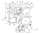
図1は本発明にかかる画像形成装置の第1実施形態を示す図である。この画像形成装置1は、互いに異なる色の画像を形成する4個の画像形成ステーション2Y(イエロー用)、2M(マゼンタ用)、2C(シアン用)および2K(ブラック用)を備えている。そして、画像形成装置1は、イエロー(Y)、マゼンタ(M)、シアン(C)およびブラック(K)の4色のトナーを重ね合わせてカラー画像を形成するカラーモードと、ブラック(K)のトナーのみを用いてモノクロ画像を形成するモノクロモードとを選択的に実行可能となっている。この画像形成装置1では、ホストコンピュータなどの外部装置から画像形成指令がCPUやメモリーなどを有するコントローラー(図示省略)に与えられると、このコントローラーが装置各部を制御して所定の画像形成動作を実行し、複写紙、転写紙、用紙およびOHP用透明シートなどのシート状の転写材Sに画像形成指令に対応する画像を形成する。   FIG. 1 is a diagram showing a first embodiment of an image forming apparatus according to the present invention. The image forming apparatus 1 includes four image forming stations 2Y (for yellow), 2M (for magenta), 2C (for cyan), and 2K (for black) that form images of different colors. The image forming apparatus 1 includes a color mode in which four color toners of yellow (Y), magenta (M), cyan (C), and black (K) are overlapped to form a color image, and black (K). A monochrome mode in which a monochrome image is formed using only toner can be selectively executed. In this image forming apparatus 1, when an image forming command is given from an external device such as a host computer to a controller (not shown) having a CPU, a memory, etc., this controller controls each part of the apparatus and executes a predetermined image forming operation. Then, an image corresponding to the image formation command is formed on a sheet-like transfer material S such as copy paper, transfer paper, paper, and an OHP transparent sheet.

各画像形成ステーション2Y、2M、2Cおよび2Kには、それぞれの色のトナー像がその表面に形成される、感光体ドラム21が設けられている。各感光体ドラム21は、その回転軸が主走査方向(図1の紙面に対して垂直な方向)に平行もしくは略平行となるように配置されており、図1中矢印D21の方向に所定速度で回転駆動される。   Each of the image forming stations 2Y, 2M, 2C, and 2K is provided with a photosensitive drum 21 on which a toner image of each color is formed. The photosensitive drums 21 are arranged such that the rotation axis thereof is parallel or substantially parallel to the main scanning direction (direction perpendicular to the paper surface of FIG. 1), and a predetermined speed is indicated in the direction of arrow D21 in FIG. Is driven to rotate.

各感光体ドラム21の周囲には、感光体ドラム21表面を所定の電位に帯電させるコロナ帯電器である帯電器22と、感光体ドラム21表面を画像信号に応じて露光することで静電潜像を形成する露光ユニット23と、該静電潜像をトナー像として顕像化する現像ユニット24と、第1スクイーズ部25と、第2スクイーズ部26と、該トナー像を中間転写ベルト31に一次転写する一次転写ユニットと、一次転写後の感光体ドラム21の表面をクリーニングするクリーニング部とが、それぞれこれらの順に感光体ドラム21の回転方向D21(図1では、時計回り)に沿って配設されている。   Around each photosensitive drum 21, a charger 22 that is a corona charger that charges the surface of the photosensitive drum 21 to a predetermined potential and an electrostatic latent image by exposing the surface of the photosensitive drum 21 according to an image signal. An exposure unit 23 that forms an image, a developing unit 24 that visualizes the electrostatic latent image as a toner image, a first squeeze unit 25, a second squeeze unit 26, and the toner image on the intermediate transfer belt 31. A primary transfer unit for primary transfer and a cleaning unit for cleaning the surface of the photosensitive drum 21 after the primary transfer are arranged along the rotation direction D21 (clockwise in FIG. 1) of the photosensitive drum 21 in this order. It is installed.

帯電器22は感光体ドラム21の表面に接触しないものであり、この帯電器22には、従来周知慣用のコロナ帯電器を用いることができる。コロナ帯電器にスコロトロン帯電器を用いた場合には、スコロトロン帯電器のチャージワイヤにはワイヤ電流が流されるとともに、グリッドには直流(DC)のグリッド帯電バイアスが印加される。帯電器22によるコロナ放電で感光体ドラム21が帯電されることで、感光体ドラム21の表面の電位が略均一の電位に設定される。   The charger 22 does not come into contact with the surface of the photosensitive drum 21, and a conventionally well-known and commonly used corona charger can be used as the charger 22. When a scorotron charger is used as the corona charger, a wire current flows through the charge wire of the scorotron charger and a direct current (DC) grid charging bias is applied to the grid. When the photosensitive drum 21 is charged by corona discharge by the charger 22, the surface potential of the photosensitive drum 21 is set to a substantially uniform potential.

露光ユニット23は、外部装置から与えられた画像信号に応じて光ビームにより感光体ドラム21表面を露光して画像信号に対応する静電潜像を形成する。この露光ユニット23としては、半導体レーザからの光ビームをポリゴンミラーにより走査させるもの、あるいは発光素子を主走査方向に配列したラインヘッド等により構成することができる。   The exposure unit 23 exposes the surface of the photosensitive drum 21 with a light beam in accordance with an image signal given from an external device to form an electrostatic latent image corresponding to the image signal. The exposure unit 23 can be constituted by a light beam from a semiconductor laser that is scanned by a polygon mirror, or a line head in which light emitting elements are arranged in the main scanning direction.

こうして形成された静電潜像に対して現像ユニット24に設けられた現像ローラー241からトナーが付与されて、静電潜像がトナーにより現像される。なお、この画像形成装置1の現像ユニット24では、キャリア液内にトナーを概略重量比20%程度に分散させた液体現像剤を用いてトナー現像が行われる。この実施形態で用いられる液体現像剤は、従来一般的に使用されている、Isopar(商標:エクソン)をキャリア液とした低濃度(1〜2wt%)かつ低粘度の常温で揮発性を有する揮発性液体現像剤ではなく、高濃度かつ高粘度の、常温で不揮発性を有する不揮発性液体現像剤である。すなわち、本実施形態における液体現像剤は、熱可塑性樹脂中へ顔料などの着色剤を分散させた平均粒径1μmの固形粒子を、有機溶媒、シリコーンオイル、鉱物油又は食用油等の液体溶媒中へ分散剤とともに添加し、トナー固形分濃度を約20%とした高粘度(HAAKE RheoStress RS600を用いて25℃の時のせん断速度1000(1/S)のときの粘弾性が30〜300mPa・s程度)の液体現像剤である。   Toner is applied to the electrostatic latent image formed in this manner from a developing roller 241 provided in the developing unit 24, and the electrostatic latent image is developed with toner. In the developing unit 24 of the image forming apparatus 1, toner development is performed using a liquid developer in which toner is dispersed in a carrier liquid in an approximate weight ratio of about 20%. The liquid developer used in this embodiment is a low-concentration (1 to 2 wt%) and low-viscosity volatility that is generally used in the past, using Isopar (trademark: Exon) as a carrier liquid. It is not an ionic liquid developer but a non-volatile liquid developer having a high concentration and high viscosity and having non-volatility at room temperature. That is, the liquid developer in the present embodiment is obtained by dispersing solid particles having an average particle diameter of 1 μm in which a colorant such as a pigment is dispersed in a thermoplastic resin in a liquid solvent such as an organic solvent, silicone oil, mineral oil, or edible oil. High viscosity with a toner solid content concentration of about 20% (HAAKE RheoStress RS600 is used, and the viscoelasticity at a shear rate of 1000 (1 / S) at 25 ° C. is 30 to 300 mPa · s. Liquid developer.

感光体ドラム21の回転方向D21において現像位置の下流側に、第1スクイーズ部25が配置されるとともに、さらに第1スクイーズ部25の下流側に第2スクイーズ部26が配置されている。これらのスクイーズ部25、26にはスクイーズローラーがそれぞれ設けられている。そして、各スクイーズローラーが感光体ドラム21の表面と当接してトナー像の余剰キャリア液やカブリトナーを除去する。なお、本実施形態では2つのスクイーズ部25、26により余剰キャリア液やカブリトナーを除去しているが、スクイーズ部の個数や配置などはこれに限定されるものではなく、例えば1個のスクイーズ部を配置してもよい。   A first squeeze portion 25 is disposed on the downstream side of the developing position in the rotation direction D 21 of the photosensitive drum 21, and a second squeeze portion 26 is disposed on the downstream side of the first squeeze portion 25. The squeeze rollers 25 and 26 are respectively provided with squeeze rollers. Each squeeze roller comes into contact with the surface of the photosensitive drum 21 to remove excess carrier liquid and fog toner from the toner image. In the present embodiment, the excess carrier liquid and fog toner are removed by the two squeeze portions 25 and 26. However, the number and arrangement of the squeeze portions are not limited to this, for example, one squeeze portion. May be arranged.

スクイーズ部25、26を通過してきたトナー像は一次転写ユニットにより中間転写ベルト31に一次転写される。中間転写ベルト31は、その表面、より詳しくはその外周面にトナー像を一時的に担持可能な像担持体としての無端状ベルトであり、複数のローラー32〜35に掛け渡されている。これらのうちローラー32はベルト駆動モーター(図示省略)に機械的に接続されて、中間転写ベルト31を図1の矢印方向D31に周回駆動するベルト駆動ローラーとして機能している。   The toner image that has passed through the squeeze portions 25 and 26 is primarily transferred to the intermediate transfer belt 31 by the primary transfer unit. The intermediate transfer belt 31 is an endless belt as an image carrier that can temporarily carry a toner image on its surface, more specifically, on its outer peripheral surface, and is stretched around a plurality of rollers 32 to 35. Among these, the roller 32 is mechanically connected to a belt drive motor (not shown), and functions as a belt drive roller that drives the intermediate transfer belt 31 in the direction of arrow D31 in FIG.

中間転写ベルト31を掛け渡されたローラー32ないし35のうち、モーターにより駆動されるのは上記したベルト駆動ローラー32のみであり、他のローラー33、34、35は駆動源を有しない従動ローラーである。また、ベルト駆動ローラー32は、ベルト移動方向D31において一次転写位置TR1の下流側、かつ後述する二次転写位置TR2の上流側で中間転写ベルト31を巻き掛けている。   Of the rollers 32 to 35 around the intermediate transfer belt 31, only the belt driving roller 32 is driven by the motor, and the other rollers 33, 34, and 35 are driven rollers having no driving source. is there. Further, the belt driving roller 32 winds the intermediate transfer belt 31 on the downstream side of the primary transfer position TR1 and the upstream side of the secondary transfer position TR2 described later in the belt moving direction D31.

一次転写ユニットは一次転写バックアップローラー271を有しており、一次転写バックアップローラー271は中間転写ベルト31を挟んで感光体ドラム21と対向して配設されている。感光体ドラム21と中間転写ベルト31とが当接する一次転写位置TR1では、これらの当接によって一次転写ニップが形成されており、該一次転写ニップで感光体ドラム21上のトナー像が中間転写ベルト31の外周面(一次転写位置TR1において下面)に転写される。各画像形成ステーション2Y、2M、2Cおよび2Kでトナー像の転写が実行されることで、各色のトナー像が中間転写ベルト31上に順次重ね合わされ、フルカラーのトナー像が形成される。一方、モノクロトナー像が形成される際には、ブラック色に対応した画像形成ステーション2Kのみにおいて、中間転写ベルト31へのトナー像転写が行われる。   The primary transfer unit has a primary transfer backup roller 271, and the primary transfer backup roller 271 is disposed to face the photosensitive drum 21 with the intermediate transfer belt 31 interposed therebetween. At the primary transfer position TR1 where the photosensitive drum 21 and the intermediate transfer belt 31 are in contact, a primary transfer nip is formed by the contact, and the toner image on the photosensitive drum 21 is transferred to the intermediate transfer belt at the primary transfer nip. 31 is transferred to the outer peripheral surface (the lower surface at the primary transfer position TR1). By transferring the toner image at each of the image forming stations 2Y, 2M, 2C, and 2K, the toner images of the respective colors are sequentially superimposed on the intermediate transfer belt 31 to form a full color toner image. On the other hand, when a monochrome toner image is formed, the toner image is transferred to the intermediate transfer belt 31 only in the image forming station 2K corresponding to the black color.

こうして中間転写ベルト31に転写されたトナー像は、ベルト駆動ローラー32への巻き掛け位置を経由して二次転写位置TR2に搬送される。この二次転写位置TR2では、中間転写ベルト31を巻き掛けられたローラー33に対して二次転写ローラー4が中間転写ベルト31を挟んで対向して固定的に配置されており、中間転写ベルト31表面と転写ローラー4の周面(ただし、凹部41を除く)とが互いに当接して転写ニップNPを形成している。すなわち、ローラー33は二次転写バックアップローラーとして機能しており、バックアップローラー33の回転軸33aは、例えばバネのような弾性部材である付勢部331によって弾性的に、かつ中間転写ベルト31に対して近接・離間移動自在に支持されている。   The toner image transferred to the intermediate transfer belt 31 in this way is conveyed to the secondary transfer position TR2 via the winding position around the belt driving roller 32. At the secondary transfer position TR2, the secondary transfer roller 4 is fixedly disposed opposite to the roller 33 around which the intermediate transfer belt 31 is wound, with the intermediate transfer belt 31 interposed therebetween. The surface and the peripheral surface of the transfer roller 4 (excluding the recess 41) are in contact with each other to form a transfer nip NP. That is, the roller 33 functions as a secondary transfer backup roller, and the rotation shaft 33a of the backup roller 33 is elastically applied to the intermediate transfer belt 31 by an urging portion 331 that is an elastic member such as a spring, for example. Are supported so that they can be moved close to and away from each other.

この二次転写位置TR2では、中間転写ベルト31上に形成された単色、あるいは複数色のトナー像がゲートローラー51(一対のローラー51a,51b)から搬送経路PTに沿って搬送される転写材Sに二次転写される。また、ゲートローラー51と二次転写位置TR2との間には、転写材Sを二次転写ローラー4や中間転写ベルト31に接触させることなく二次転写位置TR2に送り込むための転写材ガイド52が配設されている。なお、この実施形態では、液体現像剤を用いてトナー像を形成する湿式現像方式でトナー像を形成しているので、良好な転写特性を得るために、二次転写ニップNPにおいては中間転写ベルト31に対し転写材Sが高い押圧力で押圧されることが望まれる。また、液体現像剤を介在させるため、転写材Sが中間転写ベルト31に貼り付きジャムとなる可能性が高い。そこで、この画像形成装置1では、周面の一部に凹部を設け、この凹部に把持部を配設した二次転写ローラー4が用いられている。   At the secondary transfer position TR2, a single color or a plurality of color toner images formed on the intermediate transfer belt 31 is transferred from the gate roller 51 (a pair of rollers 51a and 51b) along the transfer path PT. Secondary transfer. A transfer material guide 52 for feeding the transfer material S to the secondary transfer position TR2 without contacting the secondary transfer roller 4 or the intermediate transfer belt 31 is provided between the gate roller 51 and the secondary transfer position TR2. It is arranged. In this embodiment, since the toner image is formed by a wet development method that forms a toner image using a liquid developer, an intermediate transfer belt is used in the secondary transfer nip NP in order to obtain good transfer characteristics. It is desirable that the transfer material S is pressed against the sheet 31 with a high pressing force. Further, since the liquid developer is interposed, there is a high possibility that the transfer material S sticks to the intermediate transfer belt 31 and is jammed. Therefore, in the image forming apparatus 1, a secondary transfer roller 4 is used in which a concave portion is provided in a part of the peripheral surface, and a grip portion is provided in the concave portion.

この二次転写ローラー4は、円筒の外周面の一部を切り欠いてなる凹部41が設けられたローラー基材42を有している。このローラー基材42では、回転軸4211中心に方向D4に回転自在の回転シャフト421が二次転写バックアップローラー33の回転軸33aと平行または略平行に配置されている。そして、図示を省略するモーターからの回転駆動力を受けて定位置で回転軸4211中心に方向D4に回転する。   The secondary transfer roller 4 has a roller base 42 provided with a recess 41 formed by cutting out a part of the outer peripheral surface of a cylinder. In this roller base material 42, a rotation shaft 421 that is rotatable in the direction D 4 around the rotation shaft 4211 is disposed in parallel or substantially parallel to the rotation shaft 33 a of the secondary transfer backup roller 33. Then, it receives a rotational driving force from a motor (not shown) and rotates in the direction D4 about the rotation shaft 4211 at a fixed position.

また、ローラー基材42の外周面、つまり金属プレート表面のうち凹部41の内部に相当する領域を除く表面領域にゴムや樹脂などの弾性層43が形成されている。この弾性層43はバックアップローラー33に巻き掛けられた中間転写ベルト31と対向して二次転写ニップNPを形成する。そして、二次転写ニップNPでは、バックアップローラー33が付勢部331により二次転写ローラー4側に付勢されて、二次転写ローラー4とバックアップローラー33に巻き掛けられた中間転写ベルト31との間に所定の荷重が付加されている。   Further, an elastic layer 43 such as rubber or resin is formed on the outer peripheral surface of the roller base material 42, that is, on the surface region of the metal plate surface excluding the region corresponding to the inside of the recess 41. The elastic layer 43 forms a secondary transfer nip NP so as to face the intermediate transfer belt 31 wound around the backup roller 33. In the secondary transfer nip NP, the backup roller 33 is urged toward the secondary transfer roller 4 by the urging unit 331, and the secondary transfer roller 4 and the intermediate transfer belt 31 wound around the backup roller 33 are connected. A predetermined load is applied between them.

また、凹部41の内部には、転写材Sを把持するための把持部44が配設されている。この把持部44は、凹部41の内底部からローラー基材42の外周面に立設されたグリッパ支持部材441と、グリッパ支持部材441の先端部に対して接離自在に支持されたグリッパ部材442と、転写材剥離部材449とを有している。また、グリッパ部材442はグリッパ駆動部(図示省略)と接続されている。そして、コントローラーからのアングリップ指令を受けてグリッパ駆動部が作動することでグリッパ部材442の先端部がグリッパ支持部材441の先端部から離間して転写材Sの把持準備や把持解放を行う。一方、コントローラーからのグリップ指令を受けてグリッパ駆動部が作動することでグリッパ部材442の先端部がグリッパ支持部材441の先端部に移動して転写材Sを把持する。このように把持部44を設けたことにより転写材Sを確実に保持することができ、また中間転写ベルト31に担持されるトナー像を転写材Sに転写した後に当該転写材Sを中間転写ベルト31から剥離することが可能となる。   A grip 44 for gripping the transfer material S is disposed inside the recess 41. The gripping portion 44 includes a gripper support member 441 erected on the outer peripheral surface of the roller base 42 from the inner bottom portion of the recess 41, and a gripper member 442 that is supported so as to be able to come into contact with and separate from the distal end portion of the gripper support member 441. And a transfer material peeling member 449. The gripper member 442 is connected to a gripper driving unit (not shown). In response to an ungrip command from the controller, the gripper driving unit is actuated so that the leading end of the gripper member 442 is separated from the leading end of the gripper support member 441 and the transfer material S is gripped and released. On the other hand, when the gripper driving unit is activated in response to a grip command from the controller, the leading end of the gripper member 442 moves to the leading end of the gripper support member 441 and grips the transfer material S. By providing the grip portion 44 in this manner, the transfer material S can be reliably held, and after the toner image carried on the intermediate transfer belt 31 is transferred to the transfer material S, the transfer material S is transferred to the intermediate transfer belt. It becomes possible to peel from 31.

また、転写材剥離部材449は、グリッパ部材442とグリッパ支持部材441とからなるペアの間に、二次転写ローラー4の軸方向にわたって適宜配されている。そして、転写材剥離部材449は、二次転写ローラー4の径方向外側に向かって突出移動することで、グリッパ部材442とグリッパ支持部材441とで把持していた転写材Sを二次転写ローラー4から離れる方向に押し出すように作用する。したがって、グリッパ部材442の先端部をグリッパ支持部材441の先端部から離間させて転写材Sの把持解放を行った上で、さらに転写材剥離部材449を作用させることで転写材Sを二次転写ローラー4から確実に剥離させることができる。なお、把持部44の構成については、本実施形態に限定されるものではなく、従来より公知の他の把持機構を採用してもよい。   Further, the transfer material peeling member 449 is appropriately disposed between the pair of the gripper member 442 and the gripper support member 441 along the axial direction of the secondary transfer roller 4. The transfer material peeling member 449 projects and moves outward in the radial direction of the secondary transfer roller 4, so that the transfer material S held by the gripper member 442 and the gripper support member 441 is transferred to the secondary transfer roller 4. It acts to push away from the direction. Therefore, after the gripper member 442 is separated from the tip of the gripper support member 441 to hold and release the transfer material S, the transfer material peeling member 449 is further acted on to transfer the transfer material S to the secondary transfer. The roller 4 can be reliably peeled off. In addition, about the structure of the holding part 44, it is not limited to this embodiment, You may employ | adopt other conventionally well-known holding mechanisms.

トナー像が二次転写された転写材Sは、二次転写ローラー4から搬送経路PT上に設けられた定着ユニット7へ送出される。定着ユニット7では、転写材Sに転写されたトナー像に熱や圧力などが加えられて転写材Sへのトナー像の定着が行われる。   The transfer material S on which the toner image is secondarily transferred is sent from the secondary transfer roller 4 to the fixing unit 7 provided on the transport path PT. In the fixing unit 7, heat or pressure is applied to the toner image transferred to the transfer material S to fix the toner image to the transfer material S.

なお、中間転写ベルト31を張架する4つの張架ローラー32〜35のうちローラー34は中間転写ベルト31の蛇行を修正するステアリングローラーとしても機能する。そして、このステアリングローラー34に対向するようにクリーニング部6が設けられて二次転写後に中間転写ベルト31の表面に残留するトナーやキャリア液等の残留付着物を除去する。以下、図1ないし図3を参照しつつベルト蛇行を修正する機構およびクリーニング部6の構成および動作について詳述する。   Of the four stretching rollers 32 to 35 that stretch the intermediate transfer belt 31, the roller 34 also functions as a steering roller that corrects the meandering of the intermediate transfer belt 31. A cleaning unit 6 is provided so as to face the steering roller 34 to remove residual deposits such as toner and carrier liquid remaining on the surface of the intermediate transfer belt 31 after the secondary transfer. Hereinafter, the configuration and operation of the mechanism for correcting the meandering of the belt and the cleaning unit 6 will be described in detail with reference to FIGS. 1 to 3.

図2はクリーニング部および蛇行修正機構を軸方向側から見た図であり、図3はローラー間の配置関係を示す図であり、軸方向と直交する水平方向から見た図である。これらの図中の符号80a、80bは互いに一定距離だけ離間され、それらの間に配置される一次転写バックアップローラー271などを回転自在に支持する一対の転写フレームである。これらのうち一方の転写フレーム80aには、ステアリングローラー34の傾斜移動方向を規定するガイド部材81が取り付けられており、このガイド部材81に沿ってサブフレーム82が移動方向D82に往復移動自在となっている。このサブフレーム82は、図2に示すように、ガイド部材81のガイド面81aと平行な辺部を有する六角形の板状部材であり、その辺部の各端部に当付けベアリング83、83が取り付けられるとともに、両ベアリング83、83の周面がガイド面81a上を転動自在となっている。   FIG. 2 is a diagram of the cleaning unit and the meandering correction mechanism as viewed from the axial direction side, and FIG. 3 is a diagram illustrating the positional relationship between the rollers, as viewed from the horizontal direction orthogonal to the axial direction. Reference numerals 80a and 80b in these drawings are a pair of transfer frames that are spaced apart from each other by a fixed distance and rotatably support a primary transfer backup roller 271 and the like disposed therebetween. One of the transfer frames 80a is provided with a guide member 81 that defines the tilting direction of the steering roller 34, and the sub frame 82 can reciprocate in the moving direction D82 along the guide member 81. ing. As shown in FIG. 2, the sub-frame 82 is a hexagonal plate-like member having a side portion parallel to the guide surface 81a of the guide member 81, and abutting bearings 83, 83 at each end portion of the side portion. Are attached, and the peripheral surfaces of both bearings 83, 83 are free to roll on the guide surface 81a.

サブフレーム82には、ステアリングローラー34の回転軸34aの一方端が軸支されている。このため、サブフレーム82は中間転写ベルト31の張力を受けている。また、サブフレーム82に対しては、上記張力以外に、ステアリングカム84から押上力を受ける。つまり、サブフレーム82の下面は図3に示すように転写フレーム80a側に折り曲げられており、その折り曲げ部82aに対してステアリングカム84が当接している。このステアリングカム84はステアリングモーター85の回転軸に取り付けられており、ステアリングモーター85の回転動作に応じて回転し、上方向に押し上げる力をサブフレーム82に与える。このため、装置全体を制御するコントローラー(図示省略)によりステアリングモーター85の回転駆動を制御することでガイド面81aに沿ったサブフレーム82の位置を制御可能となっている。   One end of the rotating shaft 34 a of the steering roller 34 is pivotally supported on the sub frame 82. Therefore, the sub frame 82 receives the tension of the intermediate transfer belt 31. In addition to the tension, the subframe 82 receives a pushing force from the steering cam 84. That is, the lower surface of the sub frame 82 is bent toward the transfer frame 80a as shown in FIG. 3, and the steering cam 84 is in contact with the bent portion 82a. The steering cam 84 is attached to the rotating shaft of the steering motor 85, rotates in accordance with the rotating operation of the steering motor 85, and applies a force that pushes it upward. Therefore, the position of the sub frame 82 along the guide surface 81a can be controlled by controlling the rotational drive of the steering motor 85 by a controller (not shown) that controls the entire apparatus.

このように移動するサブフレーム82に対してステアリングローラー34の回転軸34aの一方端が軸支されているが、他方端については図3に示すようにリンク部材86の一方端部に軸支されている。なお、このリンク部材86の他方端部は転写フレーム80bと連結されており、その連結点JPを回動支点として回動自在に支持されている。このため、上記のようにステアリングモーター85の回転駆動制御によってサブフレーム82を移動させることでステアリングローラー34は連結点JPを支点として傾斜移動し、中間転写ベルト31の蛇行を修正することができる。このように、本実施形態では、ステアリングカム84、ステアリングモーター85およびリンク部材86により、本発明の「蛇行修正部」が構成されている。なお、ステアリングローラー34を傾斜移動させるための構成は上記したものに限定されず、従来より多用されている機構を用いることができる。   One end of the rotating shaft 34a of the steering roller 34 is pivotally supported with respect to the subframe 82 moving in this way, but the other end is pivotally supported on one end of the link member 86 as shown in FIG. ing. The other end of the link member 86 is connected to the transfer frame 80b, and is rotatably supported with the connection point JP as a rotation fulcrum. Therefore, by moving the sub-frame 82 by the rotational drive control of the steering motor 85 as described above, the steering roller 34 can be tilted with the connection point JP as a fulcrum, and the meandering of the intermediate transfer belt 31 can be corrected. Thus, in the present embodiment, the “meander correcting portion” of the present invention is configured by the steering cam 84, the steering motor 85, and the link member 86. Note that the configuration for tilting and moving the steering roller 34 is not limited to the above-described configuration, and a mechanism that has been frequently used can be used.

クリーニング部6は、図2および図3に示すように、クリーニングローラー61と、ベルトクリーニングブレード62と、クリーニングローラー61のローラー周面と接触して当該ローラー61をクリーニングするローラークリーニングブレード63とを有している。これらのうちクリーニングローラー61はベルトクリーニングブレード62よりも上流側で中間転写ベルト31を介してステアリングローラー34と当接する。より詳しくは図3に示すように、クリーニングローラー61はスポンジローラーなどで構成され、サブフレーム82と転写フレーム80bとの間に配置されている。そして、その回転軸61aの一方端はサブフレーム82に軸支される一方、他方端はリンク部材86の一方端部に軸支されており、中間転写ベルト31と接触して従動回転する。このため、クリーニングローラー61は中間転写ベルト31を介してステアリングローラー34と当接した状態のままステアリングローラー34と一体的に傾斜移動可能となっている。なお、この点に関しては、図2に示すようにベルトクリーニングブレード62およびローラークリーニングブレード63についても同様である。また、図2中の符号64はベルトクリーニングブレード62およびローラークリーニングブレード63により掻き取った液体現像剤Lなどを回収して貯留するクリーニング用タンクである。   As shown in FIGS. 2 and 3, the cleaning unit 6 includes a cleaning roller 61, a belt cleaning blade 62, and a roller cleaning blade 63 that contacts the roller circumferential surface of the cleaning roller 61 and cleans the roller 61. is doing. Among these, the cleaning roller 61 contacts the steering roller 34 via the intermediate transfer belt 31 on the upstream side of the belt cleaning blade 62. More specifically, as shown in FIG. 3, the cleaning roller 61 is configured by a sponge roller or the like, and is disposed between the sub frame 82 and the transfer frame 80b. One end of the rotating shaft 61 a is pivotally supported by the subframe 82, and the other end is pivotally supported by one end of the link member 86, and is driven to rotate in contact with the intermediate transfer belt 31. Therefore, the cleaning roller 61 can be inclined and moved integrally with the steering roller 34 while being in contact with the steering roller 34 via the intermediate transfer belt 31. In this regard, the same applies to the belt cleaning blade 62 and the roller cleaning blade 63 as shown in FIG. 2 denotes a cleaning tank that collects and stores the liquid developer L and the like scraped by the belt cleaning blade 62 and the roller cleaning blade 63.

また、本実施形態では、転写フレーム80a、80bに対して液体塗布部9が固定的に取り付けられており、クリーニングローラー61に液体現像剤を塗布することでクリーニング性能の向上を図っている。この液体塗布部9は、塗布ローラー91と、液体塗布ヘッド92と、ポンプ93と、ならしローラー94とを備えている。この塗布ローラー91として例えばスポンジローラーが用いられており、塗布ローラー91の回転軸91aの両端がそれぞれ転写フレーム80a、80bに対して所定位置で回転自在に軸支されている。そして、塗布ローラー91のローラー周面がクリーニングローラー61に接触し、クリーニングローラー61に対して従動回転する。   In this embodiment, the liquid application unit 9 is fixedly attached to the transfer frames 80a and 80b, and the cleaning performance is improved by applying a liquid developer to the cleaning roller 61. The liquid application unit 9 includes an application roller 91, a liquid application head 92, a pump 93, and a leveling roller 94. For example, a sponge roller is used as the application roller 91, and both ends of the rotation shaft 91a of the application roller 91 are rotatably supported at predetermined positions with respect to the transfer frames 80a and 80b, respectively. Then, the roller circumferential surface of the application roller 91 comes into contact with the cleaning roller 61 and rotates following the cleaning roller 61.

この塗布ローラー91の直上に、液体塗布ヘッド92が配置され、転写フレーム80a、80bに固定された支持フレーム80cにより固定支持されている。この液体塗布ヘッド92は、図2および図3に示すように、塗布ローラー91の軸方向Xと平行に延びるボックス形状を有しており、その内部では、図3に示すように、液体現像剤Lを貯留する貯留空間921が設けられている。また、液体塗布ヘッド92の底面には、複数のノズル922が塗布ローラー91の軸方向Xに列状に配列されている。そして、液体塗布ヘッド92は配管によりクリーニング用タンク64と接続されており、その配管に介挿されたポンプ93によりクリーニング用タンク64に貯留されている液体現像剤Lが液体塗布ヘッド92に送り込まれ、各ノズル922から液体現像剤Lを塗布ローラー91に滴下して供給する。こうして塗布ローラー91に対して液体現像剤Lが供給されると、液体現像剤Lはならしローラー94により均一にならされるとともにクリーニングローラー61に塗布される。このように、本実施形態では、ならしローラー94を設けたことでクリーニングローラー61に対して均一に液体現像剤Lを塗布することができる。   A liquid application head 92 is disposed immediately above the application roller 91, and is fixedly supported by a support frame 80c fixed to the transfer frames 80a and 80b. The liquid application head 92 has a box shape extending in parallel with the axial direction X of the application roller 91 as shown in FIGS. 2 and 3, and inside the liquid developer head as shown in FIG. A storage space 921 for storing L is provided. A plurality of nozzles 922 are arranged in a row in the axial direction X of the application roller 91 on the bottom surface of the liquid application head 92. The liquid application head 92 is connected to the cleaning tank 64 by a pipe, and the liquid developer L stored in the cleaning tank 64 is sent to the liquid application head 92 by a pump 93 inserted in the pipe. The liquid developer L is dropped from each nozzle 922 and supplied to the application roller 91. When the liquid developer L is supplied to the application roller 91 in this way, the liquid developer L is made uniform by the leveling roller 94 and applied to the cleaning roller 61. Thus, in this embodiment, the liquid developer L can be uniformly applied to the cleaning roller 61 by providing the leveling roller 94.

また、クリーニングローラー61への液体現像剤の塗布によって、クリーニングローラー61によるクリーニング時に中間転写ベルト31上でのトナー固形分率が低下し、クリーニングローラー61によるトナー固形分のクリーニング除去が容易となる。なお、本実施形態では、本発明の「塗布液」としてクリーニング用タンク64に回収貯留している液体現像剤を用いているが、液体現像剤の代わりに水、キャリア液等のトナー固形分率を下げることができる液体を塗布液として供給するように構成してもよい。なお、この点については、後で説明する実施形態でも同様である。   In addition, application of the liquid developer to the cleaning roller 61 reduces the toner solid content rate on the intermediate transfer belt 31 during cleaning by the cleaning roller 61, and cleaning removal of the toner solid content by the cleaning roller 61 is facilitated. In this embodiment, the liquid developer collected and stored in the cleaning tank 64 is used as the “coating liquid” of the present invention, but the toner solid content ratio of water, carrier liquid or the like is used instead of the liquid developer. It may be configured to supply a liquid capable of lowering as a coating liquid. This also applies to embodiments described later.

以上のように、本実施形態では、中間転写ベルト31を張架するローラー32〜35のうちローラー34がステアリングローラーとしても機能し、ステアリングモーター85の駆動によりサブフレーム82を上方に押し上げることでステアリングローラー34を傾斜移動させてベルト蛇行を修正する。このため、この傾斜移動に伴ってクリーニングローラー61も傾斜移動するが、液体塗布部9は予め定められた所定位置で支持された状態のまま維持される。このように、液体塗布部9はサブフレーム82と完全に分離されているため、ステアリングモーター85に対して多大な負荷がかかるのを防止することができる。したがって、比較的低出力のステアリングモーター85を用いて中間転写ベルト31の蛇行を修正しつつクリーニングローラー61を介して液体現像剤を中間転写ベルト31に供給してクリーニング性を高めることができる。その結果、装置1の低コスト化を図ることができる。   As described above, in the present embodiment, among the rollers 32 to 35 that stretch the intermediate transfer belt 31, the roller 34 also functions as a steering roller, and the steering frame 85 is pushed upward to drive the steering by driving the steering motor 85. The belt 34 is tilted to correct the belt meandering. For this reason, the cleaning roller 61 is also tilted along with this tilting movement, but the liquid application unit 9 is maintained in a state of being supported at a predetermined position. Thus, since the liquid application part 9 is completely separated from the sub-frame 82, it is possible to prevent a great load from being applied to the steering motor 85. Therefore, the cleaning property can be improved by supplying the liquid developer to the intermediate transfer belt 31 via the cleaning roller 61 while correcting the meandering of the intermediate transfer belt 31 using the steering motor 85 having a relatively low output. As a result, the cost of the device 1 can be reduced.

また、液体塗布ヘッド92の貯留空間921内で液体現像剤を一時的に貯留した後で各ノズル922の先端開口から滴下しているため、液体塗布ヘッド92が傾くと貯留空間921内での液体現像剤の偏りが生じて塗布の均一性が損なわれる可能性がある。しかしながら、本実施形態では、上記のようにステアリングローラー34およびクリーニングローラー61が傾斜移動したとしても、液体塗布ヘッド92は転写フレーム80a、80bに固定された支持フレーム80cに固定されているため、上記問題は発生せず、液体塗布部9により液体現像剤をクリーニングローラー61に均一に塗布することができ、良好なクリーニング性能が得られる。   Further, since the liquid developer is temporarily stored in the storage space 921 of the liquid application head 92 and then dropped from the tip opening of each nozzle 922, the liquid in the storage space 921 is tilted when the liquid application head 92 is tilted. There is a possibility that the unevenness of the developer occurs and the uniformity of coating is impaired. However, in this embodiment, even if the steering roller 34 and the cleaning roller 61 are inclined as described above, the liquid application head 92 is fixed to the support frame 80c fixed to the transfer frames 80a and 80b. A problem does not occur, and the liquid application unit 9 can uniformly apply the liquid developer to the cleaning roller 61, and a good cleaning performance can be obtained.

さらに、本実施形態では、塗布ローラー91およびクリーニングローラー61のいずれもがスポンジローラーで構成されており、両者が当接した際、いずれもが弾性変形する。したがって、クリーニングローラー61の傾斜移動にかかわらず、塗布ローラー91がクリーニングローラー61のローラー周面と接触して液体現像剤を均一に塗布することができる。もちろん、塗布ローラー91およびクリーニングローラー61のいずれか一方を弾性変形可能に構成した場合も同様の作用効果が得られる。   Furthermore, in this embodiment, both the application roller 91 and the cleaning roller 61 are constituted by sponge rollers, and when both are in contact, both elastically deform. Therefore, regardless of the inclination movement of the cleaning roller 61, the application roller 91 can contact the roller peripheral surface of the cleaning roller 61 and uniformly apply the liquid developer. Of course, the same effect can be obtained when either the application roller 91 or the cleaning roller 61 is configured to be elastically deformable.

このように、第1実施形態では、ステアリングローラー34が本発明の「張架ローラー」に相当し、転写フレーム80a、80bおよび支持フレーム80cが本発明の「第1支持部」に相当し、ガイド部材81、サブフレーム82、当付けベアリング83が本発明の「第2支持部」に相当する。また、塗布ローラー91が本発明の「塗布部材」に相当し、液体塗布ヘッド92が「液体貯留部材」に相当し、ノズル922の先端開口が本発明の「供給口」に相当する。   Thus, in the first embodiment, the steering roller 34 corresponds to the “stretching roller” of the present invention, the transfer frames 80a and 80b and the support frame 80c correspond to the “first support portion” of the present invention, and the guide The member 81, the subframe 82, and the contact bearing 83 correspond to the “second support portion” of the present invention. The application roller 91 corresponds to the “application member” of the present invention, the liquid application head 92 corresponds to the “liquid storage member”, and the tip opening of the nozzle 922 corresponds to the “supply port” of the present invention.

図4は本発明にかかる画像形成装置の第2実施形態を示す図である。この第2実施形態が第1実施形態と大きく相違する点は、液体塗布部9の構成であり、その他の構成は第1実施形態と同一である。以下、相違点を中心に説明し、同一構成については同一符号を付して説明を省略する。   FIG. 4 is a view showing a second embodiment of the image forming apparatus according to the present invention. The second embodiment is greatly different from the first embodiment in the configuration of the liquid application unit 9, and other configurations are the same as those in the first embodiment. The following description will be focused on the differences, and the same components will be denoted by the same reference numerals and description thereof will be omitted.

この第2実施形態では、液体塗布部9は、スポンジなどの弾性材料で構成される塗布ブロック95と、オーバーフロー槽96と、ポンプ93とを備えている。この塗布ブロック95は、第1実施形態の塗布ローラー91に代わるものであり、本発明の「塗布部材」に相当する。より詳しくは、塗布ブロック95は、図4に示すように、クリーニングローラー61の軸方向Xに延設された直方体形状を有しており、その下方端面がクリーニングローラー61のローラー周面と摺接するように転写フレーム80a、80bにより所定位置で配置されている。また、塗布ブロック95に近接した位置でオーバーフロー槽96は転写フレーム80a、80bに固定された支持フレーム80cにより固定支持されている。このオーバーフロー槽96は、液体現像剤Lを貯留可能な貯留ボックス961と、貯留ボックス961の開口近傍と塗布ブロック95とを接続して塗布ブロック95を支持するとともに貯留ボックス961から塗布ブロック95に液体現像剤Lを案内する液体流通部材962とを有している。すなわち、貯留ボックス961の上面には開口が設けられており、ポンプ93により液体現像剤Lが貯留ボックス961に送り込まれると、貯留ボックス961の開口から液体現像剤Lが軸方向Xにおいてほぼ均一にオーバーフローする。このオーバーフローした液体現像剤Lは液体流通部材962の上面を伝わって塗布ブロック95に供給され、さらに塗布ブロック95を介してクリーニングローラー61に供給される。   In the second embodiment, the liquid application unit 9 includes an application block 95 made of an elastic material such as sponge, an overflow tank 96, and a pump 93. This application block 95 replaces the application roller 91 of the first embodiment, and corresponds to the “application member” of the present invention. More specifically, as shown in FIG. 4, the application block 95 has a rectangular parallelepiped shape extending in the axial direction X of the cleaning roller 61, and its lower end surface is in sliding contact with the roller peripheral surface of the cleaning roller 61. As described above, the transfer frames 80a and 80b are arranged at predetermined positions. Further, the overflow tank 96 is fixedly supported by a support frame 80c fixed to the transfer frames 80a and 80b at a position close to the coating block 95. The overflow tank 96 supports the application block 95 by connecting the storage box 961 capable of storing the liquid developer L, the vicinity of the opening of the storage box 961 and the application block 95, and liquid from the storage box 961 to the application block 95. A liquid circulation member 962 for guiding the developer L. That is, an opening is provided on the upper surface of the storage box 961, and when the liquid developer L is fed into the storage box 961 by the pump 93, the liquid developer L is substantially uniformly in the axial direction X from the opening of the storage box 961. Overflow. The overflowed liquid developer L is supplied to the application block 95 along the upper surface of the liquid flow member 962 and further supplied to the cleaning roller 61 via the application block 95.

このように、第2実施形態においても、第1実施形態と同様に、ステアリングローラー34およびクリーニングローラー61の傾斜移動にかかわらず、液体塗布部9は予め定められた所定位置で転写フレーム80a、80bおよび支持フレーム80cにより支持された状態のまま維持されるように構成されており、ステアリングモーター85に対して多大な負荷がかかるのを防止している。したがって、第1実施形態と同様の作用効果が得られる。   As described above, in the second embodiment, similarly to the first embodiment, regardless of the tilt movement of the steering roller 34 and the cleaning roller 61, the liquid application unit 9 is transferred to the transfer frames 80 a and 80 b at a predetermined position. And it is comprised so that it may be maintained with the state supported by the support frame 80c, and it prevents that a great load is applied with respect to the steering motor 85. FIG. Therefore, the same effect as the first embodiment can be obtained.

なお、本発明は上記した実施形態に限定されるものではなく、その趣旨を逸脱しない限りにおいて上述したもの以外に種々の変更を行うことが可能である。例えば、上記実施形態では、中間転写ベルト31に対して第1クリーニングローラー61を従動回転させているが、カウンター回転させるように構成してもよい。   The present invention is not limited to the above-described embodiment, and various modifications other than those described above can be made without departing from the spirit of the present invention. For example, in the above embodiment, the first cleaning roller 61 is driven to rotate with respect to the intermediate transfer belt 31, but it may be configured to rotate counter.

1…画像形成装置、 9…液体塗布部、 31…中間転写ベルト(像担持体ベルト)、 34…ステアリングローラー(張架ローラー)、 61…クリーニングローラー、 64…クリーニング用タンク、 80a、80b…転写フレーム、 80c…支持フレーム、 82…サブフレーム、 83…ベアリング、 84…ステアリングカム、 85…ステアリングモーター、 86…リンク部材、 91…塗布ローラー(塗布部材)、 92…液体塗布ヘッド(液体貯留部材)、 92a…ノズル、 95…塗布ブロック(塗布部材)、 961…オーバーフロー槽(液体貯留部材)、 962…液体流通部材、 L…液体現像剤、 X…軸方向   DESCRIPTION OF SYMBOLS 1 ... Image forming apparatus, 9 ... Liquid application part, 31 ... Intermediate transfer belt (image carrier belt), 34 ... Steering roller (stretching roller), 61 ... Cleaning roller, 64 ... Cleaning tank, 80a, 80b ... Transfer Frame, 80c ... Support frame, 82 ... Sub frame, 83 ... Bearing, 84 ... Steering cam, 85 ... Steering motor, 86 ... Link member, 91 ... Application roller (application member), 92 ... Liquid application head (liquid storage member) 92a ... Nozzle, 95 ... Application block (application member), 961 ... Overflow tank (liquid storage member), 962 ... Liquid flow member, L ... Liquid developer, X ... Axial direction

Claims (7)

像を担持する像担持体ベルトと、
前記像担持体ベルトを張架する張架ローラーと、
前記像担持体ベルトを介して前記張架ローラーと当接するクリーニングローラーと、
塗布液を前記クリーニングローラーに塗布する液体塗布部と、
前記液体塗布部を支持する第1支持部と、
前記クリーニングローラーが前記張架ローラーに当接している時に前記第1支持部に対して前記張架ローラーを軸方向で傾斜させる支持部材を有する第2支持部と、
前記張架ローラーが軸方向に傾斜することに応じて前記像担持体ベルトの蛇行を修正する蛇行修正部と、
を備えることを特徴とする画像形成装置。
An image carrier belt carrying an image;
A tension roller that stretches the image carrier belt;
A cleaning roller in contact with the tension roller via the image carrier belt;
A liquid application part for applying a coating liquid to the cleaning roller;
A first support part for supporting the liquid application part;
A second support portion having a support member that inclines the tension roller in the axial direction with respect to the first support portion when the cleaning roller is in contact with the tension roller;
A meandering correction unit for correcting meandering of the image carrier belt in response to the stretching roller being inclined in the axial direction;
An image forming apparatus comprising:
前記液体塗布部は、塗布液を貯留する液体貯留部材と、前記液体貯留部材に貯留された塗布液を前記クリーニングローラーに塗布する塗布部材と、を有する請求項1に記載の画像形成装置。   The image forming apparatus according to claim 1, wherein the liquid application unit includes a liquid storage member that stores the application liquid, and an application member that applies the application liquid stored in the liquid storage member to the cleaning roller. 前記塗布部材は前記クリーニングローラーと当接して弾性変形する弾性層を有する請求項2に記載の画像形成装置。   The image forming apparatus according to claim 2, wherein the application member includes an elastic layer that contacts the cleaning roller and elastically deforms. 前記塗布部材は塗布ローラーである請求項2または3に記載の画像形成装置。   The image forming apparatus according to claim 2, wherein the application member is an application roller. 前記塗布部材は、前記クリーニングローラーと摺接する塗布ブロックである請求項2または3に記載の画像形成装置。   The image forming apparatus according to claim 2, wherein the application member is an application block that is in sliding contact with the cleaning roller. 前記第1支持部は前記塗布部材の鉛直方向の上方に前記液体貯留部材を支持する請求項2ないし5のいずれか一項に記載の画像形成装置。   The image forming apparatus according to claim 2, wherein the first support portion supports the liquid storage member above a vertical direction of the application member. 前記液体貯留部材は前記クリーニングローラーの軸方向に配設された供給口を複数有し、前記供給口から塗布液を前記塗布部材に滴下する請求項6に記載の画像形成装置。   The image forming apparatus according to claim 6, wherein the liquid storage member has a plurality of supply ports arranged in an axial direction of the cleaning roller, and drops a coating liquid from the supply port onto the coating member.
JP2010255594A 2010-11-16 2010-11-16 Image forming apparatus Withdrawn JP2012108219A (en)

Priority Applications (1)

Application Number Priority Date Filing Date Title
JP2010255594A JP2012108219A (en) 2010-11-16 2010-11-16 Image forming apparatus

Applications Claiming Priority (1)

Application Number Priority Date Filing Date Title
JP2010255594A JP2012108219A (en) 2010-11-16 2010-11-16 Image forming apparatus

Publications (2)

Publication Number Publication Date
JP2012108219A true JP2012108219A (en) 2012-06-07
JP2012108219A5 JP2012108219A5 (en) 2013-12-19

Family

ID=46493924

Family Applications (1)

Application Number Title Priority Date Filing Date
JP2010255594A Withdrawn JP2012108219A (en) 2010-11-16 2010-11-16 Image forming apparatus

Country Status (1)

Country Link
JP (1) JP2012108219A (en)

Cited By (6)

* Cited by examiner, † Cited by third party
Publication number Priority date Publication date Assignee Title
US20120237266A1 (en) * 2011-03-17 2012-09-20 Seiko Epson Corporation Developing Apparatus and Image Forming Apparatus
JP2015007749A (en) * 2013-05-30 2015-01-15 株式会社リコー Image forming device
US9046827B2 (en) 2013-05-09 2015-06-02 Canon Kabushiki Kaisha Belt driving apparatus and image forming apparatus
US10254685B2 (en) 2015-08-31 2019-04-09 Canon Kabushiki Kaisha Belt conveyance device and image forming apparatus
US11422487B2 (en) 2019-01-22 2022-08-23 Hewlett-Packard Development Company, L.P. Imaging system
WO2023014399A1 (en) * 2021-08-05 2023-02-09 Hewlett-Packard Development Company, L.P. Image forming apparatus having swivel housing

Citations (3)

* Cited by examiner, † Cited by third party
Publication number Priority date Publication date Assignee Title
JP2001242680A (en) * 1999-06-14 2001-09-07 Ricoh Co Ltd Image forming device and unit device and belt device used for the same
JP2001337572A (en) * 1999-10-01 2001-12-07 Ricoh Co Ltd Image forming device
JP2002202669A (en) * 2000-12-28 2002-07-19 Ricoh Co Ltd Cleaning device and wet image forming device equipped therewith

Patent Citations (3)

* Cited by examiner, † Cited by third party
Publication number Priority date Publication date Assignee Title
JP2001242680A (en) * 1999-06-14 2001-09-07 Ricoh Co Ltd Image forming device and unit device and belt device used for the same
JP2001337572A (en) * 1999-10-01 2001-12-07 Ricoh Co Ltd Image forming device
JP2002202669A (en) * 2000-12-28 2002-07-19 Ricoh Co Ltd Cleaning device and wet image forming device equipped therewith

Cited By (6)

* Cited by examiner, † Cited by third party
Publication number Priority date Publication date Assignee Title
US20120237266A1 (en) * 2011-03-17 2012-09-20 Seiko Epson Corporation Developing Apparatus and Image Forming Apparatus
US9046827B2 (en) 2013-05-09 2015-06-02 Canon Kabushiki Kaisha Belt driving apparatus and image forming apparatus
JP2015007749A (en) * 2013-05-30 2015-01-15 株式会社リコー Image forming device
US10254685B2 (en) 2015-08-31 2019-04-09 Canon Kabushiki Kaisha Belt conveyance device and image forming apparatus
US11422487B2 (en) 2019-01-22 2022-08-23 Hewlett-Packard Development Company, L.P. Imaging system
WO2023014399A1 (en) * 2021-08-05 2023-02-09 Hewlett-Packard Development Company, L.P. Image forming apparatus having swivel housing

Similar Documents

Publication Publication Date Title
JP2012108219A (en) Image forming apparatus
JP2006267890A (en) Image forming apparatus and belt unit
US20120213542A1 (en) Image Forming Apparatus, Image Forming Method, and Recovery Device
JP2011145592A (en) Image forming apparatus and image forming method
US8023874B2 (en) Image forming apparatus having transfer bias applying section and image forming method having the same for transferring toner image
JP2009014808A (en) Image forming apparatus, method for controlling image forming apparatus and image forming method
JP2007121808A (en) Image forming apparatus
JP2011095657A (en) Image forming apparatus and image forming method
US8433226B2 (en) Image forming apparatus and transfer device including image carrier belt and driver roller
JP2011081196A (en) Image forming apparatus and image forming method
JP2011095557A (en) Image forming method and image forming apparatus
JP4547215B2 (en) How to extend the life of an endless belt
JP2012230187A (en) Collecting device and image forming device
JP2011107203A (en) Image forming method and image forming apparatus
JP2011102870A (en) Image forming apparatus and method
JP5201866B2 (en) Development device
JP2009003254A (en) Image forming apparatus, method for controlling image forming apparatus and image forming method
JP2006243052A (en) Liquid developing device
JP2007093759A (en) Developing device and image forming apparatus
JP2011175011A (en) Image forming apparatus and image forming method
JP2011095581A (en) Image forming apparatus
JP2003271026A (en) Image forming apparatus
JP2011242630A (en) Image forming device and image forming method
JP2011150067A (en) Image forming apparatus and image forming method
JP2009003268A (en) Image forming apparatus, method for controlling image forming apparatus and image forming method

Legal Events

Date Code Title Description
A521 Written amendment

Free format text: JAPANESE INTERMEDIATE CODE: A523

Effective date: 20131106

A621 Written request for application examination

Free format text: JAPANESE INTERMEDIATE CODE: A621

Effective date: 20131106

A977 Report on retrieval

Free format text: JAPANESE INTERMEDIATE CODE: A971007

Effective date: 20140509

A131 Notification of reasons for refusal

Free format text: JAPANESE INTERMEDIATE CODE: A131

Effective date: 20140520

A761 Written withdrawal of application

Free format text: JAPANESE INTERMEDIATE CODE: A761

Effective date: 20140606