JP2012168564A - Method for winding up paper to columnar body and winding paper product - Google Patents
Method for winding up paper to columnar body and winding paper product Download PDFInfo
- Publication number
- JP2012168564A JP2012168564A JP2012132024A JP2012132024A JP2012168564A JP 2012168564 A JP2012168564 A JP 2012168564A JP 2012132024 A JP2012132024 A JP 2012132024A JP 2012132024 A JP2012132024 A JP 2012132024A JP 2012168564 A JP2012168564 A JP 2012168564A
- Authority
- JP
- Japan
- Prior art keywords
- paper
- columnar body
- curl
- drum
- black paper
- Prior art date
- Legal status (The legal status is an assumption and is not a legal conclusion. Google has not performed a legal analysis and makes no representation as to the accuracy of the status listed.)
- Granted
Links
- 238000004804 winding Methods 0.000 title claims abstract description 62
- 238000000034 method Methods 0.000 title claims abstract description 44
- 230000004323 axial length Effects 0.000 claims description 13
- 235000019504 cigarettes Nutrition 0.000 claims description 9
- 238000004519 manufacturing process Methods 0.000 claims description 8
- 238000010438 heat treatment Methods 0.000 claims description 7
- 238000005520 cutting process Methods 0.000 description 10
- 239000000463 material Substances 0.000 description 8
- 238000003825 pressing Methods 0.000 description 7
- 230000002093 peripheral effect Effects 0.000 description 6
- 239000004020 conductor Substances 0.000 description 4
- 230000006866 deterioration Effects 0.000 description 3
- 239000002184 metal Substances 0.000 description 3
- 238000007664 blowing Methods 0.000 description 2
- 238000005259 measurement Methods 0.000 description 2
- 230000000630 rising effect Effects 0.000 description 2
- 238000006748 scratching Methods 0.000 description 2
- 230000002393 scratching effect Effects 0.000 description 2
- 239000007921 spray Substances 0.000 description 2
- 230000003746 surface roughness Effects 0.000 description 2
- 239000002390 adhesive tape Substances 0.000 description 1
- 238000005452 bending Methods 0.000 description 1
- 238000010586 diagram Methods 0.000 description 1
- 230000000694 effects Effects 0.000 description 1
- 238000005516 engineering process Methods 0.000 description 1
- 239000003779 heat-resistant material Substances 0.000 description 1
- 230000001771 impaired effect Effects 0.000 description 1
- 238000009434 installation Methods 0.000 description 1
- 239000002649 leather substitute Substances 0.000 description 1
- 238000004806 packaging method and process Methods 0.000 description 1
- 238000012856 packing Methods 0.000 description 1
- 230000000149 penetrating effect Effects 0.000 description 1
- 238000003860 storage Methods 0.000 description 1
Images


Landscapes
- Discharging, Photosensitive Material Shape In Electrophotography (AREA)
- Electrophotography Configuration And Component (AREA)
- Packaging Frangible Articles (AREA)
Abstract
【課題】簡易かつ高速に紙を巻装することができ、柱状体への巻装の自動化に好適な紙巻き方法及び取り扱いが容易な紙巻き品を提供する。
【解決手段】紙2に予め巻き癖を付けてからドラム1に巻装することにより、従来よりも簡易かつ高速に紙2を巻くことができ、ドラム1への巻装の自動化に好適な紙巻き方法及び取り扱いが容易な紙巻き品を提供することができる。
【選択図】図1The present invention provides a paper winding method that can easily and quickly wind paper and is suitable for automating winding on a columnar body and a paper-wrapped product that is easy to handle.
SOLUTION: By winding a paper sheet 2 on a drum 1 in advance and winding it on a drum 1, the paper sheet 2 can be wound more easily and at a higher speed than before, and the paper winding suitable for automating the winding on the drum 1 is achieved. It is possible to provide a rolled article that is easy to handle and handle.
[Selection] Figure 1
Description
本発明は、柱状体への紙巻き方法及び紙巻き品に関する。より詳しくは、本発明は、例えば、電子写真感光体ドラム表面の感光層を保護するために黒紙を巻装することができる方法及び紙巻き品に関する。 The present invention relates to a paper winding method and a paper wound product on a columnar body. More specifically, the present invention relates to a method and a paper-wrapped product capable of winding black paper to protect a photosensitive layer on the surface of an electrophotographic photosensitive drum, for example.
各種の複写機やプリンター等に使用される電子写真感光体は、通常は、表面に感光膜を有する柱状体の電子写真感光体ドラム(以下、適宜「ドラム」と言う。)として構成されている。そして、ドラム表面の感光膜の保護の観点から、保存、運搬等の際には、通常、感光膜を遮光するために黒紙等の紙をドラムの外周表面に巻装している。 An electrophotographic photosensitive member used for various copying machines, printers and the like is usually configured as a columnar electrophotographic photosensitive drum (hereinafter, referred to as “drum” as appropriate) having a photosensitive film on the surface. . From the viewpoint of protecting the photosensitive film on the drum surface, black paper or the like is usually wound around the outer peripheral surface of the drum in order to shield the photosensitive film during storage or transportation.
しかし、紙を巻装する作業は、感光膜の傷付きを防止するために通常熟練者の人手に頼って慎重に行われており、装置で行う場合と比べて、巻装する作業の作業効率が良くない上に、製品の歩留まりも良くなかった。 However, the work of winding paper is usually carried out carefully by relying on the hands of skilled workers in order to prevent the photosensitive film from being scratched. In addition, the product yield was not good.
そのため、巻装する作業を自動で行う装置が開発され、開示されている(特許文献1)。 Therefore, an apparatus for automatically performing the winding work has been developed and disclosed (Patent Document 1).
また、紙をドラムに巻装し易くするために、紙の端部を折って巻装する技術も開示されている(特許文献2)。 In addition, a technique for winding a paper by folding an end of the paper in order to easily wind the paper on a drum is also disclosed (Patent Document 2).
さらに、ドラムに巻装する紙としては、通常は、ドラムの軸方向の長さに応じた、幅の異なる種類の紙を用いていた。 Further, as the paper wound around the drum, usually, papers of different widths corresponding to the axial length of the drum were used.
しかしながら、特許文献1に記載された紙を自動で巻装する装置においては、ドラムを回転させて紙を巻装するため、この回転にかかる時間を要するという課題があった。
However, in the apparatus for automatically winding paper described in
さらに、特許文献2に記載された紙の端部を折って巻装する方法においては、折る部分の紙が余分に消費されるため、ドラムの巻装コストが高くなるという課題もあった。
Furthermore, in the method of folding and winding the end portion of the paper described in
また、従来の技術により紙を巻装したドラムにおいては、紙の端部に巻き癖が付いていないため、紙の端部がはね上がっており、紙を巻装する際の紙の取り扱いに十分な注意を要し、それに加えて、紙巻き品として箱に入れる際、紙の端部が折れたり破れたりするという課題も有していた。 In addition, in drums wound with paper according to the conventional technology, the edges of the paper are not curled so that the edges of the paper are raised so that the paper can be handled when winding the paper. In addition to this, there was a problem that the edge of the paper was broken or torn when it was put in a box as a paper roll.
また、ドラムに巻装する紙としては、ドラムの軸方向の長さに応じた、幅の異なる種類の紙を用いており、ドラムの巻装コストが高くなるという課題もあった。さらに、ドラムの軸方向の長さの方がドラムの円周長よりも長いことが多く、ロール紙等から切断して紙を得る際、ドラム1本あたりのロール紙等の幅方向の切断長さが長くなるため、切断刃の長さが長くなる、又は、切断刃の長さを短いものとした場合には、切断刃が劣化し易いという課題もあった。 In addition, as the paper wound around the drum, papers of different widths according to the axial length of the drum are used, and there is a problem that the winding cost of the drum becomes high. Further, the axial length of the drum is often longer than the circumferential length of the drum, and when the paper is obtained by cutting from roll paper or the like, the cut length in the width direction of the roll paper or the like per drum is obtained. Therefore, when the length of the cutting blade is increased or the length of the cutting blade is shortened, there is a problem that the cutting blade is likely to be deteriorated.
本発明は前記の課題に鑑みてなされたものであり、本発明の目的は、簡易かつ高速に紙を巻装することができ、柱状体への巻装の自動化に好適な紙巻き方法及び取り扱いが容易な紙巻き品を提供することに存する。 The present invention has been made in view of the above problems, and an object of the present invention is to provide a paper winding method and handling suitable for automating winding on a columnar body, which can wind paper easily and at high speed. It is to provide an easy cigarette.
本発明者らは、前記課題を解決するために鋭意研究を重ねた結果、紙に予め巻き癖を付けてから柱状体に巻装することにより、従来よりも簡易かつ高速に紙を巻くことができ、柱状体への巻装の自動化に好適な紙巻き方法及び取り扱いが容易な紙巻き品を提供することができることを見出し、本発明を完成させた。 As a result of intensive studies to solve the above problems, the inventors of the present invention can wind paper in a simpler and higher speed than before by winding a paper sheet on a paper sheet after winding the paper in advance. The present invention has been completed by finding that it is possible to provide a paper-wrapping method suitable for automating winding around a columnar body and a paper-wrapped product that is easy to handle.
即ち、本発明の要旨は、柱状体と、前記柱状体に巻装された紙と、巻装された前記紙の巻き端の一部分を前記紙に留める留め部とを備え、前記紙の留めていない部分の巻き端のはね上がりが1mm未満であることを特徴とする、紙巻き品に存する(請求項1)。 That is, the gist of the present invention includes a columnar body, paper wound around the columnar body, and a fastening portion that fastens a part of the wound end of the wound paper to the paper. It exists in the paper-rolled goods characterized by the protrusion of the winding edge of a part which is not present being less than 1 mm (Claim 1).
この時、前記柱状体が、電子写真感光体ドラムであることが好ましい(請求項2)。 At this time, it is preferable that the columnar body is an electrophotographic photosensitive drum.
また、本発明の別の要旨は、請求項1又は2に記載の紙巻き品を製造する方法であって、前記紙に巻き癖を付けてから前記柱状体に巻装することを特徴とする、紙巻き方法に存する(請求項3)。
Further, another gist of the present invention is a method for producing a paper-wrapped product according to
この時、前記紙が、前記柱状体の半径の0.7倍以上1.2倍以下の曲率半径を有する前記巻き癖を付けた部分を備えることが好ましい(請求項4)。 At this time, it is preferable that the paper has a portion with the curled surface having a radius of curvature of 0.7 to 1.2 times the radius of the columnar body (Claim 4).
また、前記紙の幅が、前記柱状体の円周長に10mmを加えた長さ以上、前記柱状体の円周長の1.5倍の長さから4mmを減した長さ未満であり、前記紙の幅方向の中央付近に前記巻き癖を付けない部分を設け、前記巻き癖を付けない前記紙の円周方向の範囲の幅が、前記柱状体の円周長の30%以上50%以下を除く範囲であることが好ましい(請求項5)。 Further, the width of the paper is not less than the length obtained by adding 10 mm to the circumferential length of the columnar body and less than the length obtained by subtracting 4 mm from the length of 1.5 times the circumferential length of the columnar body, A portion not provided with the curl is provided near the center in the width direction of the paper, and the width in the circumferential direction of the paper without the curl is 30% to 50% of the circumferential length of the columnar body. A range excluding the following is preferable (claim 5).
さらに、前記巻き癖を、前記紙を扱くことにより付けることが好ましい(請求項6)。 Furthermore, it is preferable to attach the curl by handling the paper (claim 6).
さらに、前記巻き癖を、前記紙をカールさせた状態で加熱することにより付けることが好ましい(請求項7)。 Furthermore, it is preferable that the curl is attached by heating in a state where the paper is curled (Claim 7).
さらに、前記巻き癖を、前記紙をカールさせた状態で蒸気に晒すことにより付けることが好ましい(請求項8)。 Furthermore, it is preferable that the curl is attached by exposing it to steam with the paper curled (Claim 8).
また、前記巻き癖を、前記紙を前記柱状体に巻装した後に外側となる部分に高湿空気を吹き付けてカールさせ、その形状を保持する方法により付けることが好ましい(請求項9)。 Further, it is preferable that the curl is attached by a method in which the paper is wound around the columnar body and then curled by blowing high-humidity air on the outer portion (Claim 9).
また、前記紙が巻き癖を付けていない部分を有し、前記紙の巻き癖を付けていない部分に前記柱状体を当てた後、半円状の型に入れることにより前記紙を前記柱状体に巻装することが好ましい(請求項10)。 In addition, the paper has a portion without a curl, and after applying the columnar body to the portion without the paper curl, the paper is put into a semicircular mold to put the paper into the columnar body. It is preferable to wind it around (claim 10).
さらに、本発明の別の要旨は、柱状体の円周方向の長さを幅とするロール状に巻かれた長尺紙を、前記柱状体の軸方向長さに応じて切断して前記柱状体に巻装することを特徴とする、紙巻き方法に存する(請求項11)。 Furthermore, another gist of the present invention is to cut the long paper wound in a roll shape having the width in the circumferential direction of the columnar body according to the axial length of the columnar body, and thereby form the columnar body. The present invention resides in a paper winding method characterized by winding around a body (claim 11).
この時、前記柱状体が、電子写真感光体ドラムであることが好ましい(請求項12)。 At this time, it is preferable that the columnar body is an electrophotographic photosensitive drum.
本発明によれば、従来よりも簡易かつ高速に紙を巻装することができ、柱状体への巻装の自動化に好適な紙巻き方法及び取り扱いが容易な紙巻き品を提供することができる。 ADVANTAGE OF THE INVENTION According to this invention, paper can be wound more simply and faster than before, and the paper winding method suitable for automation of winding to a columnar body and the paper winding product with easy handling can be provided.
以下、本発明の実施形態について、図面を用いて説明するが、本発明は以下の実施形態に限定されるものではなく、本発明の要旨を逸脱しない範囲において、任意に変更して実施することが出来る。 Hereinafter, embodiments of the present invention will be described with reference to the drawings. However, the present invention is not limited to the following embodiments, and may be arbitrarily modified and implemented without departing from the gist of the present invention. I can do it.
[第1実施形態]
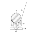
図1は本発明の紙巻き品を示す模式的な断面図、図2は本発明の紙巻き品を示す模式的な斜視図、図3は巻装する紙の上に柱状体を静置した状態を示す模式的な斜視図、図4は長尺紙を示す模式的な斜視図、図5は紙に巻き癖を付ける装置を示す模式的な断面図、図6は紙に巻き癖を付ける装置の扱き部材近傍を拡大して示す模式的な断面図、図7は曲率半径の具体的な測定方法の模式的な斜視図、図8は側面部が湾曲した型の模式的な断面図、図9は巻き癖を付けた紙に柱状体を載せている状態を示す模式的な断面図、図10は型に柱状体を入れた状態を示す模式的な断面図、図11は型に柱状体を入れた状態を示す模式的な斜視図、図12は上部にテーパを設けた型を示す模式的な断面図である。
[First Embodiment]
FIG. 1 is a schematic cross-sectional view showing a cigarette according to the present invention, FIG. 2 is a schematic perspective view showing the cigarette according to the present invention, and FIG. 3 shows a state where a columnar body is left standing on the paper to be wound. 4 is a schematic perspective view showing a long paper, FIG. 5 is a schematic cross-sectional view showing a device for attaching a curl to paper, and FIG. 6 is a diagram of an apparatus for attaching a curl to paper. 7 is a schematic cross-sectional view showing the vicinity of the handling member in an enlarged manner, FIG. 7 is a schematic perspective view of a specific method for measuring the radius of curvature, FIG. 8 is a schematic cross-sectional view of a type with a curved side surface portion, and FIG. Is a schematic cross-sectional view showing a state in which a columnar body is placed on a paper with a curl, FIG. 10 is a schematic cross-sectional view showing a state in which the columnar body is put in a mold, and FIG. 11 shows a columnar body in the mold. FIG. 12 is a schematic cross-sectional view showing a mold having a taper at the top.
(紙巻き品)
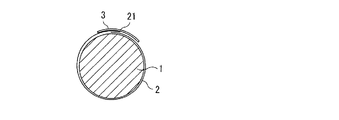
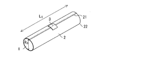
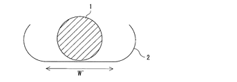
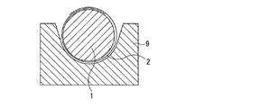
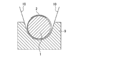
本実施形態に係る紙巻き品は、図1、図2に示すように、柱状体としてのドラム1と、紙としての黒紙2と、留め部としての留め部材3とを備えている。より具体的には、本実施形態に係る紙巻き品は、ドラム1と、ドラム1の外周表面を覆うように巻装された黒紙2とを備え、巻装された黒紙2の巻き端の一部分を留め部材3によって内側の黒紙2に留めた構成となっている。
(Paper roll)
As shown in FIGS. 1 and 2, the cigarette according to the present embodiment includes a
ドラム1は、複写機等の画像形成装置に用いられるもので、その外周表面に感光膜(図示省略)が形成されており、その軸方向の長さL0は通常200mm〜1000mm、外径R0は通常15mm〜200mmに設定されている。
The
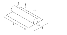
また、黒紙2は、ドラム1の感光膜を保護及び遮光するために用いられるものであり、ドラム1の外周表面を全て覆い得る大きさを有するものを用いる。具体的には、図3に示すように、ドラム1の円周方向に対応した黒紙2の幅Wが、ドラム1の円周長に、通常10mmを加えた長さ以上であり、ドラム1の円周長の1.5倍の長さから、通常4mmを減した長さ未満である。黒紙2の幅Wが短すぎる場合、ドラム1の外周表面に黒紙2で覆われない部分が生じ、ドラム1の感光膜の露出及び/又は傷付き等の可能性がある。また、黒紙2の幅Wが長すぎる場合、ドラム1を後述する半円状のくぼみを有する型9(図10、図12参照)に入れた時に、黒紙2の巻き端21が型9に当たってドラム1が浮き上がる可能性がある。
The
一方、ドラム1の軸方向に対応した黒紙2の長さLは、通常、ドラム1の軸方向の長さL0と等しいが、ドラム1の端部の正確な位置合わせを簡略化できるため、わずかに短いことが好ましく、より好ましくは2mm短くする。長さLが短すぎる場合、ドラム1の外周表面の露出部分が広くなり、露出部分に傷が付く等により、画像形成装置に装着して画像を形成する際に不具合が発生したり、感光体が外光に晒されることで劣化したりする可能性がある。また、長すぎる場合、箱等に紙巻き品を収納する際、紙2の巻き端が折れ曲がる可能性がある。
On the other hand, the length L of the
また、留め部材3は、巻装された黒紙2の巻き端の一部分を内側の黒紙2に留めるものである。留め部材3は、通常、ドラム1の軸方向の中央付近の1箇所で、黒紙2の巻き端の一部分を黒紙2に留めているが、2箇所以上で黒紙2同士を留めていても良い。
The
本実施形態において、黒紙2の留めていない部分の巻き端21(即ち、黒紙2の縁部21)は、はね上がっていないか、たとえはね上がっているとしても、この巻き端21と内側の黒紙2との最短距離(即ち、巻き端のはね上がり)が1mm未満となっている。巻き端のはね上がりが1mm未満であることによって、紙巻き品を機械等により自動で箱等に梱包する際、紙巻き品の端部が機械等に引っかかり、紙の機械等への巻き込みの可能性を減少させることが出来る。その結果、梱包機械の故障、ドラム1の表面の露出若しくは傷付き等による感光膜の劣化等を、従来よりも確実に防止することが出来る。それに加えて、巻き端のはね上がりが1mm未満であると、紙巻き品を保管する際に太陽光、蛍光灯等の外光に感光体が晒されることを防ぎ、感光膜等の劣化を従来よりも確実に抑えることも可能となる。換言すると、はね上がりが1mm以上である場合、上記の従来存在した課題が、顕著に現れる可能性がある。
In the present embodiment, the winding
(紙巻き品の製造過程)
本実施形態の紙巻き品を製造する方法に制限はないが、通常は、大きく分けて、黒紙2を用意する過程と、黒紙2に巻き癖を付ける過程と、巻き癖を付けた黒紙2をドラム1に巻装する過程と、黒紙2の巻き端を内側の黒紙2に留め部材3によって留める過程とを経て製造される。以下、この製造方法について、説明する。
(Cigarette manufacturing process)
Although there is no limitation on the method of manufacturing the cigarette according to the present embodiment, generally, the process is roughly divided into a process of preparing the
(黒紙を用意する過程)
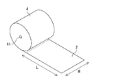
本実施形態の紙巻き品に用いられる黒紙2は、例えば、図4に示すように、ドラム1の円周方向の長さを幅Wとし、巻き芯41を有しているロール状に巻かれた長尺紙4を、ドラム1の軸方向長さL0に応じて、所望の長さLとなるように切断することで得られる。このように、長尺紙4を切断した黒紙2を用意することで、軸方向の長さL0が異なるドラム1の場合でも、ドラム1の外径R0が同じであれば、同じロール状の長尺紙4を用いることが出来る。
仮に、ドラム1の軸方向の長さL0に合わせた幅を有する長尺紙を黒紙2として用意した場合、ドラム1の軸方向の長さL0に応じた種類の異なる長尺紙4を要し、製造コスト高の要因となる。しかし、本実施形態によれば、長尺紙4の種類を減らすことができ、紙巻き品の製造コストを低下させることできる。さらに、ドラム1に巻装する黒紙2は、重ね合わせ部分があるので、ドラム1の円周長が数ミリメートル程度異なっていても、同じロール状の長尺紙4を用いることが出来る。さらに、ドラム1の円周長の方が、ドラム1の軸方向の長さL0よりも通常は短いので、長尺紙4を切断する場合に、ドラム1本あたりの長尺紙4の幅方向の切断長さが短くなるため、切断刃の長さを従来よりも短くすることが出来るとともに、より短い切断刃を採用したとしても、切断刃の劣化を従来よりも抑えることが出来る。また、長尺紙4の幅Wはドラム1の円周長に対応することから、長尺紙4の幅Wを短くできるため、長尺紙4を収納する装置を小さくするという利点も得られる。
(Process of preparing black paper)
For example, as shown in FIG. 4, the
Assuming that a long paper having a width matching the axial length L 0 of the
しかし、通常、長尺紙4から切断して得た直後の黒紙2の有する巻き癖の向きと、ドラム1に巻装する際の黒紙2を巻装する向きが異なるため、ドラム1に黒紙2を容易に巻装することが難しい。従って、ドラム1に黒紙2を巻装する前に、黒紙2に対して、ドラム1に巻装する向きと同じ方向の巻き癖を予め付けることにより、ドラム1に黒紙2を容易に巻装することが可能となる。本実施形態のように、巻装する前に黒紙2に巻き癖を付けることで上記の利点が得られるとともに、ドラム1に黒紙2を容易に巻装することが出来ることから、ドラム1に黒紙2を巻装する際に要する時間を短縮して、製造効率を向上させることも可能となる。
However, since the direction of the curl of the
(黒紙に巻き癖を付ける過程)
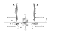
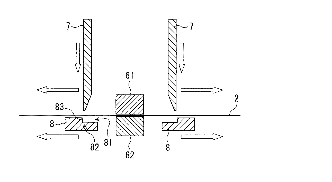
次に、黒紙2に、図5に示すような装置を用いて巻き癖を付ける。図5に示す装置は、黒紙2の両面から黒紙2を押さえる紙押さえ61及び紙押さえ62と、紙押さえ61及び紙押さえ62の両側に対向して設置された一対の扱き部材7及び型8とを備えている。
(The process of applying curl to black paper)
Next, a curl is attached to the
紙押さえ61及び紙押さえ62は、黒紙2を扱く際に黒紙2が図中の左右に移動しないように固定する手段であり、それぞれ独立して上下に可動に設けられている。紙押さえ61と紙押さえ62との間に黒紙2を挟みこみ、紙押さえ61と紙押さえ62とが互いに押圧することで、黒紙2を固定することができるようになっている。
The
扱き部材7及び型8は、黒紙2を扱くための手段である。扱き部材7は、黒紙2の長さ方向(図5及び図6の紙面に垂直な方向)に、黒紙2の長さL以上の長さに延在する部材であり、これにより黒紙2を長さ方向全体に扱くことが出来るようになっている。また、扱き部材7は、下方になるに従って次第に薄くなるように形成されている。このような形状により、扱き部材7は剛性に優れるとともに、扱き部材7と黒紙2との接触面積が小さいため、小さな力でより大きな荷重を黒紙2に与えることができるようになっている。また、扱き部材7は、上下及び左右に可動に設けられている。
The handling
一方、型8は、扱き部材7と同様に、黒紙2の長さ方向に黒紙2の長さL以上の長さに延在する部材であり、これにより黒紙2を幅方向全体に扱くことが出来るようになっている。また、型8の上側部には、紙押さえ61及び紙押さえ62に近い側の縁部に切り欠き81が形成され、これにより黒紙2を扱くための段差82が設けられている。なお、この段差82の高さは、黒紙2の素材、厚さ、所望の巻き癖の程度等により、適宜設定すればよい。また、型8は、左右に可動するように設けられている。
On the other hand, the
さらに、扱き部材7と型8との位置関係は、扱き部材7の先端と型8の段差82とが対向している。前記先端と前記段差82との間に黒紙2を挟みこみ、両者が一体となって駆動して黒紙2を扱くことで、黒紙2に巻き癖を付けることができるようになっている。
Further, the positional relationship between the handling
上記の装置を用いて黒紙2に巻き癖を付ける際には、まず、紙押さえ61を降ろし、紙押さえ62を上げて黒紙2に強く押し付けることにより、黒紙2を固定する。また、扱き部材7が上方にあって型8と離れている状態で、黒紙2を扱き部材7と型8との間に通し、扱き部材7を降ろす。これにより、扱き部材7及び型8と黒紙2とが接し、扱き部材7及び型8により黒紙2が挟み込まれる。そして、紙押さえ61及び紙押さえ62で黒紙2を固定し、かつ、扱き部材7が黒紙2に接した状態で、扱き部材7及び型8をそれぞれ紙押さえ61及び紙押さえ62に対して遠ざける方向に駆動させることにより、黒紙2が扱き部材7によって扱かれ、黒紙2に巻き癖を付けることができる。
When the curl is attached to the
なお、巻き癖を付けた黒紙2の曲がり具合は、黒紙2の縁部22の巻き癖を付けた部分を曲線と見たときの曲率半径で表すことができる。この曲率半径の大きさは、例えば、上記の型8の切り欠き81の側面部83と扱き部材の側部71との最短距離の値δ、扱き部材7の黒紙2への押し付け力、扱き部材7及び型8をそれぞれ黒紙押さえ61及び黒紙押さえ62に対して遠ざける方向に駆動させる際の速度等の条件によって決定される。本発明の紙巻き方法において、黒紙2はドラム1の半径の通常0.7倍以上、また、通常1.2倍以下の曲率半径を有する巻き癖を付けた部分を備える。曲率半径が小さすぎる場合、後述する図10に示す半円状のくぼみを有する型9に黒紙2とともにドラム1を入れたときに、黒紙2の巻き癖を付けた部分がドラム1に密着しない可能性がある。また、曲率半径が大きすぎる場合、黒紙2がドラム1に密着するように巻装できなかったり、上記の黒紙2の縁部21のはね上がりが1mm以上となったりする可能性がある。曲率半径が上記の範囲内にあることで、留め部材3を貼り付ける簡易な動作又は機構により、容易にドラム1に密着させることが可能となる。
The degree of bending of the
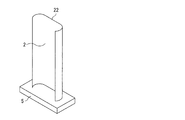
なお、曲率半径の値としては、例えば、図7に示すように、水平な平板上に黒紙2を立て置き、黒紙2の縁部22の巻き癖を付けた部分がなす曲率半径を用いることができる。
As the value of the radius of curvature, for example, as shown in FIG. 7, the radius of curvature formed by the portion of the
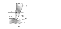
また、型8の切り欠き81の側面部83は、図8に示すように、湾曲断面を有する滑らかな曲面をそなえるようにしていてもよい。この場合、扱き部材7の側部71側の最下端部と側面部83とが触れないように、扱き部材7の側部71の最下端部は、当該湾曲の曲率半径よりも小さな曲率半径を有する曲面にすることが好ましい。
Further, as shown in FIG. 8, the
図6におけるδの値、即ち、側面部83と側部71との間隔は、通常、黒紙2の厚さ以上であり、型8及び扱き部材7の形状並びに黒紙2の材質等によって適宜選択される。δの値が黒紙2の厚さより小さい場合には扱くことが出来ず、黒紙2の厚さ以上であっても、δの値を小さく設定すれば巻き癖の曲率半径は小さくなり、大きく設定すれば曲率半径が大きくなるため、所望の巻き癖が付くように適切に設定すれば良い。
The value of δ in FIG. 6, that is, the distance between the
また、扱き部材7の紙2への押し付け力についても、型8及び扱き部材7の材質、表面粗度、形状並びに黒紙2の材質等によって適宜選択される。押し付け力の大きさが小さすぎる場合、巻き癖の曲率半径の大きさが一定にならなかったり、十分な曲率半径が得られなかったりする可能性があり、大きすぎる場合、黒紙2に傷が付いたり、黒紙2が破断したりする可能性がある。
Further, the pressing force of the handling
そして、扱き部材7及び型8をそれぞれ紙押さえ61及び紙押さえ62に対して遠ざける方向に駆動させる際の速度も、型8及び扱き部材7の材質、表面粗度、形状並びに黒紙2の材質等によって適宜選択される。中でも、黒紙2に傷が付いたり、黒紙2が破断したりしない速度の範囲内で、速度が速ければ速いほど、本発明の紙巻き品の生産性が向上するため好ましい。
The speed at which the handling
また、黒紙2に巻き癖を付けない黒紙2の円周方向の範囲の幅W’(図9参照)が、ドラム1の円周長の通常30%以上、また、通常50%以下を除く範囲、即ち、黒紙2に巻き癖を付ける黒紙2の円周方向の範囲の幅(図9においてW’を除く部分)が、ドラム1の円周長の通常30%以上、また、通常50%以下であり、これ以外の範囲が巻き癖を付けない範囲となる。巻き癖を付けない範囲がこの範囲より小さいと、黒紙2の巻き癖を付けた部分の曲率半径を大きくしないとドラム1に黒紙2を巻装することが困難になる可能性がある。また、巻き癖を付けない範囲がこの範囲を超えると、後述する半円状のくぼみを有する型9(図10参照)に入れた際にドラム1に黒紙2が密着しない部分が生じる可能性がある。
Further, the width W ′ (see FIG. 9) in the circumferential direction of the
本実施形態においては、黒紙2の幅Wが、ドラム1の円周長に10mmを加えた長さ以上であり、ドラム1の円周長の1.5倍の長さから4mmを減した長さ未満であり、前記紙の幅方向の中央付近に前記巻き癖を付けない部分を設け、巻き癖を付けない黒紙2の円周方向の範囲の幅W’が、ドラム1の円周長の30%以上50%以下を除く範囲であるものとして説明する。
In this embodiment, the width W of the
(巻き癖を付けた黒紙をドラムに巻装する過程)
本過程においては、図9に示すように、黒紙2の巻き癖を付けていない部分にドラム1を当てた後、図10に示すような断面半円状のくぼみを有する型9に黒紙2とともにドラム1を入れることにより、黒紙2をドラム1に巻装する。この時、型9が有する半円状のくぼみ部分の半径の長さは、ドラム1の半径に黒紙2の厚さを加えた程度の長さである。この長さであることにより、ドラム1に黒紙2を密着させることが出来る。
(The process of winding black paper with curly wrap around a drum)
In this process, as shown in FIG. 9, after the
また、より簡易かつ高速にドラム1に黒紙2を巻装するために、型9に任意の変更を加えることが出来る。例えば、図12に示すように、型9の上部に、半円状部に接するようなテーパ10を設けても良い。さらに、型9に入れるドラム1表面の傷つき防止の観点から、型9が有する半円状のくぼみ部分の内部を、人工皮革、フェルト等の柔軟材料で覆っても良い。また、型9に黒紙2とともにドラム1を入れた後、ドラム1を上方から軽く押さえることが、ドラム1に黒紙2をより密着させることが出来るため好ましい。
Further, in order to wind the
なお、型9の長さ(図10の紙面に垂直な方向への長さ)は、黒紙2をドラム1に巻装できる限り、適宜設定することができる。例えば、型9の長さが黒紙2の長さL以上であっても良い。また、型9の長さが黒紙2の長さLより短い場合であっても、黒紙2をドラム1に巻装できる限り、その長さ及び設置方法に制限はなく、例えば、図11に示すように、10mm程度の長さの型9を、ドラム1と黒紙2とを支持できる程度の間隔をおいて、2箇所程度設置する等複数設置することで、黒紙2をドラム1に巻装することができる。
Note that the length of the mold 9 (the length in the direction perpendicular to the paper surface of FIG. 10) can be appropriately set as long as the
(黒紙の巻き端を黒紙に留める過程)
そして、本過程において、黒紙2の巻き端の一部分を、留め部材3によって内側の黒紙2に留める。留め部材3を形成する手段としては、人手によっても良いし、装置によっても良い。この際、巻き端の留めていない部分のはね上がりは、上記の範囲にある。また、重ね合わせ部の上側の黒紙2に留め部材3で先に留め、次に黒紙2を巻き方向に引張しながら下側の黒紙2に留めることで、黒紙2をより密着させてドラム1に巻装することが出来る。
(The process of fastening the end of black paper to black paper)
In this process, a part of the winding end of the
本実施形態においては、留め部材3の幅(ドラム1の軸方向長さ)は、ドラム1の長さL0の通常5%以上15%以下である。また、留め部材3の長さ(ドラム1の円周方向の長さ)は、通常1cm以上5cm以下である。通常は、図2に示すように、上記の範囲の幅及び長さを有する留め部材3によって、黒紙2の長さL方向の中央付近で黒紙2同士を留めるが、巻き端の留めていない部分のはね上がりが上記の範囲にある限り、黒紙2同士を留める位置に制限はない。
In the present embodiment, (the axial length of the drum 1) width of the
[第2実施形態]
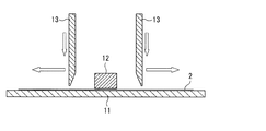
次に、本発明の第2実施形態について説明する。図13は紙に巻き癖を付ける第2実施形態に係る装置を示す模式的な断面図である。図13において、図5と同じ符号で示す部分は図5と同様なものを示し、これらの説明は一部省略する。また、第2実施形態においては、下記の黒紙に巻き癖を付ける過程が第1実施形態と異なり、それ以外は第1実施形態と同様に実施する。
[Second Embodiment]
Next, a second embodiment of the present invention will be described. FIG. 13 is a schematic cross-sectional view showing an apparatus according to a second embodiment for attaching a curl to paper. In FIG. 13, the same reference numerals as those in FIG. 5 denote the same parts as in FIG. Further, in the second embodiment, the process of applying curl to the following black paper is different from the first embodiment, and the other processes are performed in the same manner as in the first embodiment.
図13に示す装置は、弾性部材としてのゴム板11と、黒紙2を上方より押さえる紙押さえ12と、紙押さえ12の両側に対向して設置された扱き部材13を備えている。
The apparatus shown in FIG. 13 includes a
ゴム板11は、紙2の全体を静置しうる大きさを有する板である。これにより、黒紙2を長さ方向全体に扱くことができるようになっている。
The
紙押さえ12は、黒紙2を扱く際に黒紙2が図中の左右に移動しないように固定する手段であり、上下に可動に設けられている。そして、ゴム板11の上に黒紙2を静置し、その上から紙押さえ12を押圧することで、黒紙2を固定することができるようになっている。
The
扱き部材13は、黒紙2の長さ方向(図13の紙面に垂直な方向)に、黒紙2の長さL以上の長さに延在する部材であり、これにより黒紙2を長さ方向全体に扱くことが出来るようになっている。また、扱き部材13は、下方になるに従って次第に薄くなるように形成されていて、この形状により、小さな力でより大きな荷重を紙2に与えることができる。また、扱き部材13は、上下及び左右に可動するように設けられている。
The handling
上記の装置を用いて黒紙2に巻き癖を付ける際には、まず、ゴム板11に黒紙2を静置し、紙押さえ12を降ろして黒紙2に強く押し付けることにより、黒紙2を固定する。そして、扱き部材13を降ろして、ゴム板11と扱き部材13とで黒紙2を挟み込む。この時、扱き部材13の先端(下端)は、ゴム板11を弾性変形させながら、ゴム板11内に沈み込んだ状態で、黒紙2と圧接する。そして、黒紙2が固定され、かつ、扱き部材13と黒紙2とが接した状態で、扱き部材13をそれぞれ紙押さえ12に対して遠ざける方向に駆動させることにより、黒紙2が扱き部材13によって扱かれ、黒紙2に所望の巻き癖を付けることができる。
When the curl is attached to the
以上のように、このような構成によっても、第1実施形態と同様に、黒紙2に巻き癖を付けることが可能である。
As described above, even with such a configuration, it is possible to add curl to the
[第3実施形態]
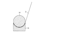
次に、本発明の第3実施形態について説明する。図14は、黒紙2をカールさせた状態で加熱することにより巻き癖を付ける装置を示す模式的な断面図である。図14において、図1と同じ符号で示す部分は図1と同様なものを示し、これらの説明は一部省略する。また、第3実施形態においては、下記の黒紙2に巻き癖を付ける過程が第1実施形態と異なり、それ以外は第1実施形態と同様に実施する。
[Third Embodiment]
Next, a third embodiment of the present invention will be described. FIG. 14 is a schematic cross-sectional view showing an apparatus for attaching a curl by heating the
図14に示す装置は、ドラム14と、ドラム14を入れた時に密着しうるくぼみを有する型15とを備える。
The apparatus shown in FIG. 14 includes a
ドラム14は金属等の熱伝導性材料で形成された、上下方向に可動な部材である。また、ドラム14は、黒紙2に付ける巻き癖と同様の曲率半径を有する。従って、黒紙2をドラム14に密着させて加熱することにより、所望の巻き癖を黒紙2に付けることができるようになっている。
The
さらに、型15は、黒紙2とともにドラム14を置いた時に、黒紙2の巻き癖をつけたい部分と密着できる程度の大きさの密着面を有する。
Further, the
上記の装置を用いて巻き癖を付ける際には、ドラム14を型15から離した状態で型15の上に黒紙2を置き、ドラム14を下げて、ドラム14と型15とで黒紙2の巻き癖を付ける部分を挟み込む。そして、図14に示すように、ドラム14に黒紙2を密着させて、所望の巻き癖の曲率半径を有するようにカールさせる。この状態でドラム14を加熱し、黒紙2を加熱することにより、所望の巻き癖を黒紙2に付けることができる。
When applying the curl using the above apparatus, the
また、ドラム14に金属等の熱伝導性材料を用いる代わりに、型15に金属等の熱伝導性材料を用いても良い。この場合、型15を加熱することで黒紙2を加熱することができ、上記の場合と逆の黒紙2の向きから加熱することができる。また、ドラム14及び型15の両方を、熱伝導性材料で形成しても良い。
Further, instead of using a thermally conductive material such as metal for the
以上のように、このような構成によっても、第1実施形態と同様に、黒紙2に巻き癖を付けることが可能である。
As described above, even with such a configuration, it is possible to add curl to the
[第4実施形態]
次に、本発明の第4実施形態について説明する。図15は、黒紙2をカールさせた状態で蒸気に晒すことにより巻き癖を付ける装置の模式的な断面図である。図15において、図14と同じ符号で示す部分は図14と同様なものを示し、これらの説明は一部省略する。また、第4実施形態においては、下記の黒紙2に巻き癖を付ける過程が第1実施形態と異なり、それ以外は第1実施形態と同様に実施する。
[Fourth Embodiment]
Next, a fourth embodiment of the present invention will be described. FIG. 15 is a schematic cross-sectional view of an apparatus for applying curl by exposing the
図15に示す装置は、ドラム16と、ドラム16を入れた時に密着しうるくぼみ及び穴部17aを有する型17と、蒸気を発生する蒸気発生装置18とを備える。
The apparatus shown in FIG. 15 includes a
ドラム16は、黒紙2につける巻き癖と同様の曲率半径を有して形成された、上下方向に可動な部材である。従って、黒紙2をドラム16に密着させて黒紙2を蒸気に晒すことにより、所望の巻き癖を黒紙2に付けることができるようになっている。型17には、蒸気が通じるように鉛直方向に貫通する穴部17aが形成されている。穴部17aは、本実施形態においては3個設けた例により説明するが、1個又は2個でも良く、4個以上でも良い。また、型17は、蒸気に晒されるので、耐熱性の材料から構成される。さらに、型17は、黒紙2とともにドラム16を置いた時に、黒紙2の巻き癖をつけたい部分と密着できる程度の大きさの密着面を有する。蒸気発生装置18は、蒸気を発生させる装置であって、型17の下方に設けられている。このため、蒸気発生装置18で発生した蒸気は、穴部17aを通って、黒紙2の下部に到達する構成になっている。
The
上記の装置を用いて巻き癖を付ける際には、ドラム16を型17から離した状態で型17上に黒紙2を置き、ドラム16を下げて、ドラム16及び型17で黒紙2の巻き癖を付けたい部分を挟み込む。そして、図15に示すように、ドラム16に黒紙2を密着させて、所望の巻き癖の曲率半径を有するようにカールさせる。この状態で、蒸気発生装置18から蒸気を発生させる。発生した蒸気が、型17の穴部17aを通って黒紙2に到達し、黒紙2が蒸気に晒される。その結果、所望の巻き癖を黒紙2に付けることができる。
When applying the curl using the above apparatus, the
なお、第4実施形態に係る紙巻き方法における蒸気の温度、蒸気を吹き付ける時間等は、所望の巻き癖の程度により、適宜設定すればよい。 In addition, what is necessary is just to set suitably the temperature of the vapor | steam in the paper winding method which concerns on 4th Embodiment, the time to spray vapor | steam, etc. according to the grade of the desired curl.
また、穴部17aを有する型17の代わりに、穴部を有さない型17と穴部を有する中空状のドラムとを用い、中空状のドラムの内部に蒸気を流通させることにより、上記の場合と逆の黒紙2の向きから蒸気に晒すことができる。また、穴部を有する中空状のドラムと穴部17aを有する型17とを、両方組み合わせて用いても良い。
Further, instead of the
以上のように、このような構成によっても、第1実施形態と同様に、紙2に巻き癖を付けることが可能である。
As described above, even with such a configuration, it is possible to attach a curl to the
[第5実施形態]
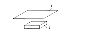
次に、本発明の第5実施形態について説明する。図16は、第5実施形態に係る巻き癖を付ける装置を示した模式的な斜視図である。図16において、図14と同じ符号を示す部分は図14と同様なものを示し、これらの説明は一部省略する。また、第5実施形態においては、下記の黒紙2に巻き癖を付ける過程が第1実施形態と異なり、それ以外は第1実施形態と同様に実施する。
[Fifth Embodiment]
Next, a fifth embodiment of the present invention will be described. FIG. 16 is a schematic perspective view showing an apparatus for attaching a curl according to the fifth embodiment. In FIG. 16, the same reference numerals as those in FIG. 14 denote the same parts as in FIG. 14, and a part of these descriptions will be omitted. Further, in the fifth embodiment, the process of applying curl to the following
第5実施形態に係る装置は、高湿空気発生装置19を備えており、図16に示すように、ドラム1に巻装した後に外側となる部分が下方となるように黒紙2を設置した場合、黒紙2の下部が高湿空気に晒されるようになっている。
The apparatus according to the fifth embodiment includes a high-humidity
上記の装置を用いて巻き癖を付ける際には、高湿空気発生19から発生した高湿空気を、黒紙2のドラム1に巻装した後に外側となる部分に吹き付ける。その結果、黒紙2がカールし、この形状を保持することにより、黒紙2に巻き癖を付けることができる。
When the curl is attached using the above-described apparatus, the high-humidity air generated from the high-
この際、高湿空気の温度、湿度、吹き付ける時間等を変化させることにより、巻き癖を付けた部分の曲率半径を所望のものとすることが出来る。本実施形態における高湿空気の温度、湿度、吹き付ける時間等は、所望の巻き癖の程度により、適宜設定すればよい。 At this time, by changing the temperature, humidity, blowing time, and the like of the high-humidity air, the radius of curvature of the portion with the curl can be made desired. What is necessary is just to set suitably the temperature of high humidity air in this embodiment, humidity, the time to spray, etc. according to the grade of a desired curl.
以上のように、このような構成によっても、第1実施形態と同様に、黒紙2に巻き癖を付けることが可能である。
As described above, even with such a configuration, it is possible to add curl to the
[その他]
以上、本発明の実施の形態を説明したが、本発明は上記の構成に限定されるものではなく、本発明の趣旨を逸脱しない範囲で、上記の構成を適宜変更して実施することが出来る。
[Others]
Although the embodiment of the present invention has been described above, the present invention is not limited to the above-described configuration, and can be implemented by appropriately changing the above-described configuration without departing from the spirit of the present invention. .
例えば、紙に巻き癖を付ける方法としては、上記の1種の方法のみに限らず、2種以上の方法を任意に組み合わせて行うことができる。 For example, the method for attaching curl to paper is not limited to the above-described one method, and two or more methods can be arbitrarily combined.
また、例えば、柱状体は円柱状のドラムに限らず、多角柱であっても良い。
また、例えば、紙も黒紙に限らず、ドラム表面を遮光し、感光膜の露出及び/又は傷付き等を防止するという本発明の効果を著しく損なわない範囲で、任意の色、厚さ等のものを用いることが出来る。
また、例えば、留め部も留め部材に限らず、紙の端部を内側の紙に留めることができれば、粘着テープ等の任意のもので形成することが出来る。
For example, the columnar body is not limited to a cylindrical drum, and may be a polygonal column.
In addition, for example, the paper is not limited to black paper, and any color, thickness, etc., as long as the effect of the present invention of shielding the drum surface and preventing exposure and / or scratching of the photosensitive film is not significantly impaired. Can be used.
Further, for example, the fastening portion is not limited to the fastening member, and can be formed of any material such as an adhesive tape as long as the end of the paper can be fastened to the inner paper.
さらに、例えば、上記した実施形態を任意に組み合わせて実施することが出来る。 Furthermore, for example, the above-described embodiments can be arbitrarily combined.
以下、実施例を基に本発明をさらに詳細に説明するが、本発明の内容は以下の内容に限定されるものではない。 EXAMPLES Hereinafter, although this invention is demonstrated further in detail based on an Example, the content of this invention is not limited to the following content.
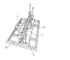
図17は、実施例で用いた紙を扱くための装置を示す模式的な斜視図である。図17に示す装置は、黒紙2と、紙押さえ61と、扱き部材7と、型8と、それらを固定する土台20とから構成される。黒紙2は、紙押さえ61及びそれに対応する紙押さえ(図17では図示省略した。図5の紙押さえ62に対応する。)により土台20に固定されている。扱き部材7と型8との間に黒紙2を挟みこみ、両者を紙面右方向に引くことにより、黒紙2が扱かれる。この図17に示す装置を用いて紙を扱き、扱いた部分の曲率半径を測定した。なお、黒紙2として、下記表1に示す規格の黒紙を用いた。
FIG. 17 is a schematic perspective view showing an apparatus for handling paper used in the examples. The apparatus shown in FIG. 17 includes a
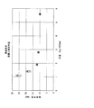
扱く際の条件は、図5におけるδの値を0.1mm、扱き速度を50mm/秒とした。実際に扱いている間のδは、装置の剛性により若干大きくなっている可能性がある。また、扱きの操作も手動で行ったため、扱き速度が±50%程度変動していた可能性がある。この条件下、扱き部材の黒紙への押し付け力(荷重)を変化させ、曲率半径を測定した。なお、荷重の値は、4種類の長さL(柱状体に巻装する際の柱状体の軸方向の長さL0)の異なる黒紙を扱き、それぞれ黒紙の長さを250mmに換算した時の荷重の値とした。 The handling conditions were such that the value of δ in FIG. 5 was 0.1 mm, and the handling speed was 50 mm / sec. During actual handling, δ may be slightly larger due to the rigidity of the device. Moreover, since the handling operation was also performed manually, the handling speed may have fluctuated by about ± 50%. Under this condition, the pressing force (load) of the handling member to the black paper was changed, and the radius of curvature was measured. In addition, the load value handles four types of length L (the length L 0 in the axial direction of the columnar body when wound around the columnar body), and the length of each black paper is converted to 250 mm. It was set as the value of the load at the time.
各荷重において測定を4回行い、それぞれの測定結果を表2に示し、図18にプロットした。図18の横軸は、黒紙の長さLを250mmに換算した時の扱き部材により与えられる荷重を表し、縦軸は曲率半径を表す。 The measurement was performed four times at each load, and the measurement results are shown in Table 2 and plotted in FIG. The horizontal axis in FIG. 18 represents the load applied by the handling member when the length L of the black paper is converted to 250 mm, and the vertical axis represents the radius of curvature.
図18に示すように、荷重を変化させることで、曲率半径を変化させることができる。 As shown in FIG. 18, the radius of curvature can be changed by changing the load.
1 ドラム
2 黒紙
3 留め部材
4 長尺紙
41 巻き芯
5 平板
7 扱き部材
8 型
9 半円状のくぼみを有する型
10 テーパ
11 ゴム板
12 紙押さえ
13 扱き部材
14 柱状体
15 型
16 柱状体
17 型
17a 穴部
18 蒸気発生装置
19 高湿空気発生装置
20 土台
21 巻き端、黒紙の縁部
22 黒紙の縁部
61、62 紙押さえ
71 扱き部材の側部
81 切り欠き
82 段差
83 切り欠きの側面部
DESCRIPTION OF
Claims (10)
該紙の幅が、該柱状体の円周長に10mmを加えた長さ以上、該柱状体の円周長の1.5倍の長さから4mmを減らした長さ未満であり、
該紙に、該柱状体の半径の0.7倍以上、1.2倍以下の曲率半径となる巻き癖を付けた部分を有し、
該紙の幅方向の中央付近に、該巻き癖をつけない部分を有し、かつ
該巻き癖をつけない部分の幅が、該柱状体の円周長の30%以上、50%以下を除く範囲である
ことを特徴とする紙巻き品。 A columnar body, a paper wound around the columnar body, and a fastening portion that fastens a part of the winding end of the wound paper to the paper,
The width of the paper is not less than the length obtained by adding 10 mm to the circumferential length of the columnar body and less than the length obtained by reducing 4 mm from the length of 1.5 times the circumferential length of the columnar body,
The paper has a portion with a curl that has a radius of curvature not less than 0.7 times and not more than 1.2 times the radius of the columnar body,
Near the center in the width direction of the paper, there is a portion where the curl is not applied, and the width of the part where the curl is not applied is excluding 30% or more and 50% or less of the circumferential length of the columnar body. Cigarettes characterized by being in range.
ことを特徴とする、請求項1に記載の紙巻き品。 The paper roll according to claim 1, wherein the roll-up end of the portion where the paper is not fastened is less than 1 mm.
ことを特徴とする、請求項1又は2に記載の紙巻き品。 The cigarette according to claim 1 or 2, wherein the columnar body is an electrophotographic photosensitive drum.
該紙の幅が、該柱状体の円周長に10mmを加えた長さ以上、該柱状体の円周長の1.5倍の長さから4mmを減らした長さ未満であり、
該紙に、該柱状体の半径の0.7倍以上、1.2倍以下の曲率半径となる巻き癖を付けた部分を有し、
該紙の幅方向の中央付近に、該巻き癖をつけない部分を有し、かつ
該巻き癖をつけない部分の幅が、該柱状体の円周長の30%以上、50%以下を除く範囲であり、
該紙に該巻き癖を付けてから該柱状体に巻装する
ことを特徴とする紙巻き方法。 A method of manufacturing a paper-wrapped article comprising a columnar body, paper wound around the columnar body, and a fastening portion that fastens a part of a winding end of the wound paper to the paper,
The width of the paper is not less than the length obtained by adding 10 mm to the circumferential length of the columnar body and less than the length obtained by reducing 4 mm from the length of 1.5 times the circumferential length of the columnar body,
The paper has a portion with a curl that has a radius of curvature not less than 0.7 times and not more than 1.2 times the radius of the columnar body,
Near the center in the width direction of the paper, there is a portion where the curl is not applied, and the width of the part where the curl is not applied is excluding 30% or more and 50% or less of the circumferential length of the columnar body. Range,
A paper winding method comprising attaching the curl to the paper and then winding the paper on the columnar body.
ことを特徴とする、請求項4に記載の紙巻き方法。 5. The paper winding method according to claim 4, wherein the curl is attached by handling the paper.
ことを特徴とする、請求項4又は5に記載の紙巻き方法。 The paper winding method according to claim 4 or 5, wherein the curl is attached by heating in a state where the paper is curled.
ことを特徴とする、請求項4〜6の何れか一項に記載の紙巻き方法。 The paper winding method according to any one of claims 4 to 6, wherein the curl is attached by being exposed to steam in a state where the paper is curled.
ことを特徴とする、請求項4〜7の何れか一項に記載の紙巻き方法。 The curl is attached by a method of curling high-humidity air on a portion that becomes the outer side after the paper is wound around the columnar body and maintaining the shape thereof. The paper winding method according to any one of the above.
該紙の巻き癖を付けていない部分に該柱状体を当てた後、半円状の型に入れることにより該紙を該柱状体に巻装する
ことを特徴とする、請求項4〜8の何れか一項に記載の紙巻き方法。 The paper has a portion that is not curled,
The paper is wound around the columnar body by placing the columnar body on a portion of the paper where the curl is not attached and then placing the columnar body in a semicircular mold. The paper winding method according to any one of the above.
該柱状体の軸方向長さに応じて切断して該柱状体に巻装する
ことを特徴とする、請求項4〜9の何れか1項に記載の紙巻き方法。
A long paper wound in the form of a roll whose width is the length of the columnar body in the circumferential direction,
The paper winding method according to any one of claims 4 to 9, wherein the columnar body is cut according to an axial length of the columnar body and wound around the columnar body.
Priority Applications (1)
| Application Number | Priority Date | Filing Date | Title |
|---|---|---|---|
| JP2012132024A JP5240382B2 (en) | 2012-06-11 | 2012-06-11 | Paper-wrapping method and paper-wrapped product on a columnar body |
Applications Claiming Priority (1)
| Application Number | Priority Date | Filing Date | Title |
|---|---|---|---|
| JP2012132024A JP5240382B2 (en) | 2012-06-11 | 2012-06-11 | Paper-wrapping method and paper-wrapped product on a columnar body |
Related Parent Applications (1)
| Application Number | Title | Priority Date | Filing Date |
|---|---|---|---|
| JP2007329534A Division JP5303926B2 (en) | 2007-12-21 | 2007-12-21 | Paper-wrapping method and paper-wrapped product on a columnar body |
Publications (2)
| Publication Number | Publication Date |
|---|---|
| JP2012168564A true JP2012168564A (en) | 2012-09-06 |
| JP5240382B2 JP5240382B2 (en) | 2013-07-17 |
Family
ID=46972704
Family Applications (1)
| Application Number | Title | Priority Date | Filing Date |
|---|---|---|---|
| JP2012132024A Expired - Fee Related JP5240382B2 (en) | 2012-06-11 | 2012-06-11 | Paper-wrapping method and paper-wrapped product on a columnar body |
Country Status (1)
| Country | Link |
|---|---|
| JP (1) | JP5240382B2 (en) |
Citations (15)
| Publication number | Priority date | Publication date | Assignee | Title |
|---|---|---|---|---|
| JPS61125980U (en) * | 1985-01-28 | 1986-08-07 | ||
| JPH03105376A (en) * | 1989-09-20 | 1991-05-02 | Ricoh Co Ltd | Image forming device |
| JPH03126878U (en) * | 1990-04-04 | 1991-12-20 | ||
| JPH0462683U (en) * | 1990-10-05 | 1992-05-28 | ||
| JPH05257412A (en) * | 1992-03-11 | 1993-10-08 | Sharp Corp | Process kit protective material |
| JPH0650062U (en) * | 1992-12-08 | 1994-07-08 | 株式会社リコー | Electrophotographic photosensitive drum protection sheet |
| JPH07152283A (en) * | 1993-11-29 | 1995-06-16 | Mita Ind Co Ltd | Packing method of electrophotographic photoreceptor |
| JPH086436A (en) * | 1994-06-17 | 1996-01-12 | Ricoh Co Ltd | Buffer material for storage and transportation of electrophotographic photoreceptors |
| JPH0816038A (en) * | 1994-06-30 | 1996-01-19 | Fuji Electric Co Ltd | Winding method for protective sheet of electrophotographic photoreceptor |
| JPH1072075A (en) * | 1996-08-27 | 1998-03-17 | Fuji Electric Co Ltd | Packaging method for photoreceptor for electrophotography |
| JP2000109008A (en) * | 1998-10-12 | 2000-04-18 | Techno Ote:Kk | Winding method of sheet material on cylindrical surface |
| JP2002284109A (en) * | 2001-03-23 | 2002-10-03 | Tokyo Autom Mach Works Ltd | Fin seal package and its turret type packaging machine |
| JP2005195853A (en) * | 2004-01-07 | 2005-07-21 | Fuji Denki Gazo Device Kk | Protection paper for electrophotographic photoreceptor and protection method for electrophotographic photoreceptor |
| JP2005254537A (en) * | 2004-03-10 | 2005-09-22 | Konica Minolta Medical & Graphic Inc | Lithographic printing plate material, its packaging method, printing plate and printing method |
| JP3720176B2 (en) * | 1997-09-22 | 2005-11-24 | 三菱化学株式会社 | Automatic paper winding machine |
-
2012
- 2012-06-11 JP JP2012132024A patent/JP5240382B2/en not_active Expired - Fee Related
Patent Citations (15)
| Publication number | Priority date | Publication date | Assignee | Title |
|---|---|---|---|---|
| JPS61125980U (en) * | 1985-01-28 | 1986-08-07 | ||
| JPH03105376A (en) * | 1989-09-20 | 1991-05-02 | Ricoh Co Ltd | Image forming device |
| JPH03126878U (en) * | 1990-04-04 | 1991-12-20 | ||
| JPH0462683U (en) * | 1990-10-05 | 1992-05-28 | ||
| JPH05257412A (en) * | 1992-03-11 | 1993-10-08 | Sharp Corp | Process kit protective material |
| JPH0650062U (en) * | 1992-12-08 | 1994-07-08 | 株式会社リコー | Electrophotographic photosensitive drum protection sheet |
| JPH07152283A (en) * | 1993-11-29 | 1995-06-16 | Mita Ind Co Ltd | Packing method of electrophotographic photoreceptor |
| JPH086436A (en) * | 1994-06-17 | 1996-01-12 | Ricoh Co Ltd | Buffer material for storage and transportation of electrophotographic photoreceptors |
| JPH0816038A (en) * | 1994-06-30 | 1996-01-19 | Fuji Electric Co Ltd | Winding method for protective sheet of electrophotographic photoreceptor |
| JPH1072075A (en) * | 1996-08-27 | 1998-03-17 | Fuji Electric Co Ltd | Packaging method for photoreceptor for electrophotography |
| JP3720176B2 (en) * | 1997-09-22 | 2005-11-24 | 三菱化学株式会社 | Automatic paper winding machine |
| JP2000109008A (en) * | 1998-10-12 | 2000-04-18 | Techno Ote:Kk | Winding method of sheet material on cylindrical surface |
| JP2002284109A (en) * | 2001-03-23 | 2002-10-03 | Tokyo Autom Mach Works Ltd | Fin seal package and its turret type packaging machine |
| JP2005195853A (en) * | 2004-01-07 | 2005-07-21 | Fuji Denki Gazo Device Kk | Protection paper for electrophotographic photoreceptor and protection method for electrophotographic photoreceptor |
| JP2005254537A (en) * | 2004-03-10 | 2005-09-22 | Konica Minolta Medical & Graphic Inc | Lithographic printing plate material, its packaging method, printing plate and printing method |
Also Published As
| Publication number | Publication date |
|---|---|
| JP5240382B2 (en) | 2013-07-17 |
Similar Documents
| Publication | Publication Date | Title |
|---|---|---|
| TWI487677B (en) | Roll of flexible glass and method for winding | |
| CN111129609B (en) | Conveyor rollers and winders | |
| JP5303926B2 (en) | Paper-wrapping method and paper-wrapped product on a columnar body | |
| CN113451540B (en) | Pole piece rolling method | |
| JP2011251797A (en) | Take-up roll | |
| JP5240382B2 (en) | Paper-wrapping method and paper-wrapped product on a columnar body | |
| KR200488326Y1 (en) | Strip winding apparatus for preventing reel mark | |
| CN113148734A (en) | Ultra-thin lithium foil strip transfer method and device | |
| JP6407805B2 (en) | Web manufacturing method and web | |
| JP5418656B2 (en) | Winding body, manufacturing method thereof, and laminated sheet containing long sheet | |
| JP2020117257A (en) | Decorative box for package wound body | |
| JP5653961B2 (en) | Packing material and metal tubular body supply method | |
| JP5661312B2 (en) | Winding core | |
| AU2018101385A4 (en) | Gift wrapping | |
| JP2023088086A (en) | Winding core for web winding and web winding method | |
| KR101940835B1 (en) | Film sheet winding method using winding roll | |
| JP5933384B2 (en) | Material roll storage device and material roll storage method | |
| JP3029814B2 (en) | Rolls for winding paper | |
| JP4186019B2 (en) | Winding core | |
| KR100281424B1 (en) | Protection pad for products packing band | |
| JP5626021B2 (en) | Method for manufacturing electrode winding body | |
| CN212711845U (en) | Auxiliary sleeving device for film winding drum | |
| JP5121495B2 (en) | Roll screen end protection method and roll screen end protection material | |
| JP2005250217A (en) | Storage box for rolled photosensitive material package | |
| JP2006089120A (en) | Packaging method and processing line for lithographic printing plate |
Legal Events
| Date | Code | Title | Description |
|---|---|---|---|
| A621 | Written request for application examination |
Free format text: JAPANESE INTERMEDIATE CODE: A621 Effective date: 20120709 |
|
| TRDD | Decision of grant or rejection written | ||
| A01 | Written decision to grant a patent or to grant a registration (utility model) |
Free format text: JAPANESE INTERMEDIATE CODE: A01 Effective date: 20130305 |
|
| A61 | First payment of annual fees (during grant procedure) |
Free format text: JAPANESE INTERMEDIATE CODE: A61 Effective date: 20130318 |
|
| FPAY | Renewal fee payment (event date is renewal date of database) |
Free format text: PAYMENT UNTIL: 20160412 Year of fee payment: 3 |
|
| R150 | Certificate of patent or registration of utility model |
Free format text: JAPANESE INTERMEDIATE CODE: R150 |
|
| LAPS | Cancellation because of no payment of annual fees |