JP2012168022A - Method for diagnosing quality of concrete-based structure - Google Patents
Method for diagnosing quality of concrete-based structure Download PDFInfo
- Publication number
- JP2012168022A JP2012168022A JP2011029377A JP2011029377A JP2012168022A JP 2012168022 A JP2012168022 A JP 2012168022A JP 2011029377 A JP2011029377 A JP 2011029377A JP 2011029377 A JP2011029377 A JP 2011029377A JP 2012168022 A JP2012168022 A JP 2012168022A
- Authority
- JP
- Japan
- Prior art keywords
- sound pressure
- pressure response
- excitation force
- time characteristic
- sound
- Prior art date
- Legal status (The legal status is an assumption and is not a legal conclusion. Google has not performed a legal analysis and makes no representation as to the accuracy of the status listed.)
- Granted
Links
Images


Landscapes
- Investigating Or Analyzing Materials By The Use Of Ultrasonic Waves (AREA)
Abstract
Description
本発明は、コンクリート系構造物の品質診断方法に関し、詳しくは、コンクリート系構造物の健全部と、表層部の剥離、ひび割れ、あるいはコンクリート打設時の型枠への充填不足による空洞などが発生している異常部の判別・診断を、外部から非破壊検査で行うことができるコンクリート系構造物の品質診断方法に関する。 The present invention relates to a method for diagnosing quality of a concrete structure, and more particularly, a sound part and a surface layer part of a concrete structure are peeled off, cracked, or a cavity is generated due to insufficient filling of a formwork when placing concrete. The present invention relates to a quality diagnostic method for a concrete structure that can be used for non-destructive inspection from the outside to determine and diagnose an abnormal part.
コンクリート系構造物の表層部の剥離、ひび割れ、更にはコンクリート打設時の型枠への充填不足による空洞の有無などを、打音によって診断する方法は、従来から多くの提案がされており、本出願人も、例えば、特許文献1〜2に示すように複数の提案をしている。
There have been many proposals for a method of diagnosing the presence or absence of cavities due to insufficient peeling of cracks in the surface layer of concrete-based structures, as well as insufficient filling of the formwork during concrete placement. The present applicant has also made a plurality of proposals as shown in
本出願人による先提案技術を含めて、多数提案されている従来技術は、いずれも、ハンマー等による構造物表面への打撃音を、人の聴覚によって感覚的に判断していた旧来の方法に替えて、各種センサー等の測定器を用いて解析することで、感覚に頼らずに且つ熟練を必要とすることなく定量的に判別できるようにすることを目的としたものである。 Many of the prior arts, including the prior art proposed by the present applicant, are based on the conventional methods that have been sensuously judged by the human sense of sound from hitting the surface of the structure with a hammer or the like. Instead, it is intended to be able to quantitatively discriminate without relying on a sense and requiring skill by performing analysis using measuring instruments such as various sensors.
本出願人は、当該技術について更に研究を続けたところ、人の聴覚によって構造物の品質種別を判別する旧来の方法は打撃音の音色を聞き分けることで判別していることが判り、測定器による解析によって構造物の品質種別を判別する従来技術は、打撃音の音の大きさによって判別している方法と、音色に相当する量によって判別している方法とに分類されることが判った。 The Applicant continued further research on the technology, and found that the traditional method of discriminating the quality type of a structure by human hearing was discriminating by distinguishing the tone of the hitting sound. It has been found that the prior art for discriminating the quality type of a structure by analysis is classified into a method of discriminating based on the volume of the hitting sound and a method of discriminating based on the amount corresponding to the timbre.
特許文献1に記載の技術は、打撃音の音圧の大きさによって構造物の品質種別を判別する方法であり、コンクリート表面を打撃手段により打撃して振動を生じさせ、この打撃位置から離れた位置に配置したマイクロホンにより、コンクリート中を伝搬し空気中に放射された音(打撃音)を採取して電気信号に変換し、この信号を解析することによりコンクリートの健全度を判定する方法において、打撃入力値の時間変化が既知となるハンマーを用いて打撃を行い、この打撃入力の既知量とコンクリート中を伝搬し空気中に放射された音(打撃音)とを解析することにより、コンクリート健全度を判定することを特徴とするコンクリート健全度判定方法である。
The technique described in
特許文献2に記載の技術は、打撃音の音色に相当する量によって構造物の品質種別を判別する方法であり、被測定対象の構造物に、衝撃を加えることで得られる応答信号を加えた衝撃力の大きさで除することで得られた規準化応答を用いる方法であり、規準化応答の後期応答乃至は全時間応答を用い、信号集合の各信号に対して1/Nオクターブバンド分析したレベル値から、健全部のデータ集合と異常部のデータ集合を教師信号とする各周波数バンドにおける品質種別毎の平均値μ1、μ2と標準偏差σ1、σ2を求め、各バンドにおける品質種別間の規準化距離δを特定の式(1)で求め、得られた各規準化距離δの値の内、値が大であるものから任意の個数の値を抽出し、抽出した値から構造物の各部位における品質種別を判別できるものである。
The technique described in
しかし、これらの診断方法では、あらかじめ健全部と異常部などのカテゴリー別の対応パラメータを定義し、その弁別境界値をセットするプロセスを要する。また、この設定値の精度如何により、あるいは、選択したパラメータが何であるかにより、診断精度が大きく左右され、適用できる問題の範囲が限定されるという問題があった。 However, these diagnosis methods require a process of defining corresponding parameters for each category such as a healthy part and an abnormal part in advance and setting the discrimination boundary value thereof. Further, there is a problem that the diagnostic accuracy is greatly influenced by the accuracy of the set value or the selected parameter, and the range of applicable problems is limited.
そこで、本発明の課題は、剥離等の異常部に生じる現象として必ず観測される定性的な現象に着目し、前記の設定値の精度や選択したパラメータに左右されず、診断の確実性が高く、既存の診断方法では適用が困難であった対象に対しても適用可能となるコンクリート系構造物の品質診断方法を提供することにある。 Therefore, an object of the present invention is to focus on a qualitative phenomenon that is always observed as a phenomenon that occurs in an abnormal part such as peeling, and is highly reliable in diagnosis regardless of the accuracy of the set value or the selected parameter. An object of the present invention is to provide a method for diagnosing the quality of a concrete structure that can be applied to an object that has been difficult to apply with existing diagnostic methods.
上記本発明の課題は下記の手段により達成される。
1.被測定対象であるコンクリート系構造物に、インパクトハンマーの如き任意の打撃手段により打撃を与え、該打撃手段から得られる加振力と、打撃箇所に近接した位置に設置された受音系システムの受音手段により得られる音圧応答とを計測することによって、コンクリート系構造物の品質を診断する方法において、
前記加振力の時間特性波形と、前記音圧応答の時間特性波形とを比較することにより診断する方法であって、
加振力の正符号を、前記打撃手段の打撃接触面に圧縮力が働く方向とし、音圧応答の正符号を、静止圧より高い圧力の方向とした場合に、
(A−1)被測定対象に加振力が働いている間又はこれの後続過程において、音圧応答の絶対値が、受音系システムに暗騒音以上の音圧を感知したか否かを区別する閾値である規定値を初めて超えたとき、その符号の正負を観察し、該音圧応答の符号が正であること、
(A−2)被測定対象に加振力が働いている間において、加振周波数以上の高周波数成分が、音圧応答に表れること、
のうち、上記(A−1)、(A−2)の少なくとも1つの現象が観察された場合に、前記被測定対象に異常があると診断することを特徴とするコンクリート系構造物の品質診断方法。
The object of the present invention is achieved by the following means.
1. The concrete structure to be measured is struck by any striking means such as an impact hammer, the excitation force obtained from the striking means, and the sound receiving system installed at a position close to the striking location. In a method for diagnosing the quality of a concrete structure by measuring the sound pressure response obtained by the sound receiving means,
A method of making a diagnosis by comparing a time characteristic waveform of the excitation force and a time characteristic waveform of the sound pressure response,
When the positive sign of the excitation force is the direction in which the compressive force acts on the striking contact surface of the striking means, and the positive sign of the sound pressure response is the direction of pressure higher than the static pressure,
(A-1) Whether or not the absolute value of the sound pressure response senses a sound pressure higher than background noise in the sound receiving system while the excitation force is acting on the object to be measured or in the subsequent process. When the specified value, which is a threshold value to be distinguished, is exceeded for the first time, the sign of the sign is observed, and the sign of the sound pressure response is positive,
(A-2) While the excitation force is acting on the object to be measured, a high frequency component higher than the excitation frequency appears in the sound pressure response.
Among these, when at least one phenomenon of the above (A-1) and (A-2) is observed, it is diagnosed that there is an abnormality in the object to be measured. Method.
2.加振力と音圧応答の時間特性波形が、加振力の最大値と、加振力が働いている間における音圧応答の負の最大値で規準化されていることを特徴とする前記1に記載のコンクリート系構造物の品質診断方法。 2. The time characteristic waveform of the excitation force and the sound pressure response is normalized by the maximum value of the excitation force and the negative maximum value of the sound pressure response while the excitation force is working. A quality diagnostic method for a concrete structure according to 1.
3.(B−1)加振力の時間特性波形が、正弦半波形状をし、音圧応答の時間特性波形が、前記加振力の時間特性を示す波形の符号を反転したような正弦半波形状をしていること、
(B−2)音圧応答の時間特性波形における負の最大値が生じる時刻が、加振力の時間特性波形における最大値が生じる時刻よりも遅れて生じること、
(B−3)音圧応答の時間特性波形の最初の立ち上がりが、加振力の時間特性波形の最初の立ち上がりよりも遅れて生じること、
のうち、上記(B−1)〜(B−3)の少なくとも1つの現象が観察された場合に、被測定対象が健全であると診断することを特徴とする前記1又は2に記載のコンクリート系構造物の品質診断方法。
3. (B-1) A sine half wave in which the time characteristic waveform of the excitation force has a sine half wave shape, and the time characteristic waveform of the sound pressure response is obtained by inverting the sign of the waveform indicating the time characteristic of the excitation force. Have a shape,
(B-2) the time at which the negative maximum value in the time characteristic waveform of the sound pressure response occurs is delayed from the time at which the maximum value in the time characteristic waveform of the excitation force occurs;
(B-3) The first rise of the time characteristic waveform of the sound pressure response occurs later than the first rise of the time characteristic waveform of the excitation force.
The concrete according to 1 or 2 above, wherein when the at least one phenomenon of (B-1) to (B-3) is observed, the object to be measured is diagnosed as being healthy. Quality diagnosis method for system structures.
4.前記1〜3のいずれかに記載のコンクリート系構造物の品質診断方法により診断された被測定対象の異常が、
(C−1)コンクリート系構造物の一部が剥離した状態、
(C−2)コンクリート系構造物の内部に空洞が存在する状態、
(C−3)コンクリート系構造物の内部あるいは内部から外部につながるひび割れが存在する状態、
(C−4)コンクリートの打設時の型枠への充填不足による空洞が存在する状態、
(C−5)コンクリート系構造物の母材に対して他の比較的薄い材料が、(1)規定の接着状態ではなく、剥離的特性を有している状態、及び/又は(2)ひび割れや空洞などを有する状態、
のうち、上記(C−1)〜(C−5)の少なくとも1つの状態であることを特徴とする前記1〜3のいずれかに記載のコンクリート系構造物の品質診断方法。
4). The abnormality of the measurement target diagnosed by the quality diagnostic method for a concrete structure according to any one of 1 to 3,
(C-1) A state in which a part of the concrete structure is peeled off,
(C-2) A state in which a cavity exists inside the concrete structure,
(C-3) A state in which there is a crack leading from the inside to the outside of the concrete structure,
(C-4) A state in which there is a cavity due to insufficient filling of the formwork when placing concrete,
(C-5) The other relatively thin material with respect to the base material of the concrete-based structure is (1) not in the prescribed adhesion state, but in a state of having peeling properties, and / or (2) cracking Or having a cavity,
Among them, the method for diagnosing quality of a concrete structure according to any one of the
前記1に示す発明によれば、判別のためのパラメータの事前調整のようなプロセスを必要とせず、複数のパラメータを動員して判別することが可能であり、診断の確実性が高く、既存の診断方法では適用が困難であった対象に対しても適用が可能なコンクリート系構造物の品質診断方法を提供することができる。
また、従来の診断方法とは異なる独立の情報に基づく方法であり、従来の診断方法と併用して使用することができ、それにより品質診断の精度を高めることができる。更に、独立の情報に基づく方法であることから、従来の診断方法では検出できなかった現象の判別も可能となり得る。
According to the first aspect of the present invention, it is possible to mobilize and discriminate a plurality of parameters without requiring a process such as parameter pre-adjustment for discrimination, and the diagnosis is highly reliable. It is possible to provide a method for diagnosing the quality of a concrete structure that can be applied even to an object that is difficult to apply by the diagnostic method.
Moreover, it is a method based on independent information different from the conventional diagnostic method, and can be used in combination with the conventional diagnostic method, thereby improving the accuracy of the quality diagnosis. Furthermore, since the method is based on independent information, it may be possible to determine a phenomenon that could not be detected by a conventional diagnostic method.
前記2に示す発明によれば、加振力の最大値と、加振力が働いている間における音圧応答の負の最大値を規準化することにより、加振力の時間特性波形と、音圧応答の時間特性波形との比較が容易になり、診断の容易性も向上することになる。 According to the invention shown in 2, the time characteristic waveform of the exciting force is normalized by normalizing the maximum value of the exciting force and the negative maximum value of the sound pressure response while the exciting force is working, Comparison with the time characteristic waveform of the sound pressure response is facilitated, and the ease of diagnosis is improved.
前記3に示す発明によれば、被測定対象の異常部のみならず、健全部も判別・診断することができ、診断の正確性が向上することになる。 According to the third aspect of the present invention, not only an abnormal part to be measured but also a healthy part can be discriminated and diagnosed, and the accuracy of diagnosis is improved.
前記4に示す発明によれば、被測定対象に、いずれかの異常がある、と分かる。 According to the fourth aspect of the present invention, it can be understood that there is any abnormality in the measurement object.
本発明に係るコンクリート系構造物の品質診断方法は、被測定対象をコンクリートを全部又は一部に使用した建築物やトンネル等の構造物とし、インパクトハンマー等の打撃手段により被測定対象であるコンクリート系構造物に与えた加振力と、打撃箇所に近接した位置に設置されたマイクロホン等の受音系システムの受音手段により得られる音圧応答とを測定し、それぞれの時間特性波形(いわゆる「時間波形」)を観察することによって、健全部と異常部を判別し、コンクリート系構造物の品質を診断する方法である。 The method for diagnosing the quality of a concrete structure according to the present invention is a concrete in which the object to be measured is a structure such as a building or a tunnel using concrete in whole or in part, and the object to be measured by impact means such as an impact hammer. The excitation force applied to the system structure and the sound pressure response obtained by the sound receiving means of the sound receiving system such as a microphone installed at a position close to the hitting point are measured, and each time characteristic waveform (so-called This is a method of diagnosing the quality of a concrete structure by observing a “time waveform”) to distinguish between a healthy part and an abnormal part.
「加振力」とは、圧電素子などを用いた力センサー(フォースセンサー)を用いて計測される力の単位を持つ物理量で、対象に加えられた力の大きさを出力するように調整された計測器(例えば、インパクトハンマー等。)によって計測することができるものである。 "Excitation force" is a physical quantity with a unit of force measured using a force sensor (force sensor) using a piezoelectric element, etc., and is adjusted to output the magnitude of the force applied to the target. It can be measured by a measuring instrument (for example, an impact hammer).
「音圧応答」とは、打撃によって、被測定対象に生じた振動が、空気中に放射されて音(空気振動、粗密波)となったものを、マイクロホン等の音圧センサーで捉えたものをいう。 “Sound pressure response” refers to a sound pressure sensor, such as a microphone, that uses vibration to generate sound (air vibration, close-packed waves) radiated into the air due to impact. Say.
本発明において、「コンクリート系構造物」とは、コンクリートに限定されず、建築構造・土木構造あるいはこれらの部品として使われる幅広い材料を含み、例えば、レンガ、アスファルト、金属、石材、木材、その他多様な人造材料などがあり、本発明はこれらを材料とする構造物にも適用できる。 In the present invention, the term “concrete structure” is not limited to concrete, but includes a wide range of materials used as building structures, civil structures, or parts thereof, such as bricks, asphalt, metals, stones, wood, and other various materials. The present invention can also be applied to structures using these as materials.
先ず、本発明に係るコンクリート系構造物の品質診断方法に用いられる、測定手段の構成の一例を説明する。
本発明にかかるコンクリート系構造物の品質診断方法に用いられる測定手段構成の一例を示す概略構成図を、図1に示す。測定に際して必要な構成は、打撃手段1、加振力検出器・アンプ2、受音手段3、音圧検出器・アンプ4、AD変換器5、コンピュータ6である。
First, an example of the structure of the measuring means used for the quality diagnosis method for a concrete structure according to the present invention will be described.
FIG. 1 shows a schematic configuration diagram showing an example of a configuration of a measuring means used in the quality diagnosis method for a concrete structure according to the present invention. The components required for the measurement are the striking means 1, excitation force detector /
打撃手段1としては、この種の打音検査技術分野において用いられる公知公用の手段であって、概ね一定の条件での衝撃を付与する手段を特別の制限無く用いることができ、例えば、好ましい打撃手段としては、衝撃波が得られるような概ね一定の加振力で、構造物表面に対して打撃を加えることができるインパクトハンマーによる打撃を挙げることができる。
ここに言うインパクトハンマーとは、打撃入力値の時間変化が既知となるように、圧電素子などを用いたセンサー(フォースセンサー)を内蔵したハンマーを指す。即ち、図1に示す打撃手段1と加振力検出器・アンプ2の機能を併せ持つハンマーである。
The hitting means 1 is a publicly known means used in this type of sound inspection technology field, and means for giving an impact under a substantially constant condition can be used without any particular limitation. Examples of the means include striking with an impact hammer capable of striking the surface of the structure with a substantially constant excitation force capable of obtaining a shock wave.
The impact hammer here refers to a hammer having a built-in sensor (force sensor) using a piezoelectric element or the like so that the change with time of the hitting input value is known. In other words, the hammer has the functions of the striking means 1 and the excitation force detector /
また、受音手段3としては、この種の打音検査技術分野において用いられる公知公用の手段を用いることができる。例えば、前記打撃手段によって打撃を付与された衝撃点(例えば、インパクトハンマーの打撃点)に近接した位置で、被測定対象であるコンクリート系構造物自体を伝播した伝播打撃音(振動)を空気振動として採取するマイクロホン31と、該マイクロホンを内装すると共に、受音方向が解放されているフード部材32とで構成された受音手段3を用い、コンクリート系構造物表面に近接ないし密接した状態での測定を行う構成を挙げることができる。
The sound receiving means 3 may be a publicly known means used in this type of sound inspection technology field. For example, in the position close to the impact point (for example, impact point of impact hammer) to which the impact is given by the impacting means, the propagation impact sound (vibration) propagated through the concrete structure itself to be measured is air-vibrated. As a sound receiving means 3 composed of a
尚、フード付きマイクのフード部材32は、ハンマーで加振した位置の点的な局部的な変形から発生する音よりも、同変形が被診断部材に伝搬して、被診断部材の構造的特徴を反映した振動となった後の音の放射を、より効率的に捉えるように工夫されたもので、例えば、特開2001−311724号公報に述べられた効果を期待できる。
The
打撃手段1と加振力検出器・アンプ2から得られた加振力と、受音手段3と音圧検出器・アンプ4から得られた音圧応答とを、AD変換器5を介してデジタル信号に変換し、コンピュータ6において、該加振力と音圧応答の測定データを時間特性波形として表示することができる。
本発明に係るコンクリート系構造物の品質診断方法は、上記のようにして得られた加振力と音圧応答の時間特性波形とを比較することによって、被測定対象であるコンクリート系構造物の品質を診断する方法である。
An excitation force obtained from the striking means 1 and the excitation force detector /
The method for diagnosing the quality of a concrete structure according to the present invention compares the excitation force obtained as described above with the time characteristic waveform of the sound pressure response, thereby comparing the concrete structure being measured. It is a method of diagnosing quality.
各時間特性波形において、加振力の正符号は、ハンマーの打撃接触面に圧縮力が働く方向、音圧応答の正符号は、静止圧(大気圧、基準圧)より高い圧力の方向であり、健全部を加振した場合は、加振の正弦半波が正に、近傍のマイクロホンの音圧応答が負に観察されることになる。
また、加振力と音圧応答の時間特性波形を、加振力の最大値と、加振力が働いている間における音圧応答の負の最大値で規準化することが好ましい。即ち、加振力については、得られた加振力を加振力の最大値で除することにより得られる値を、音圧応答については、得られた音圧応答を被測定対象に加振力が働いている間における音圧応答の負の最大値で除することにより得られる値を、それぞれ縦軸として表示した時間特性波形とすることが好ましい。
In each time characteristic waveform, the positive sign of the excitation force is the direction in which the compressive force acts on the hammering contact surface, and the positive sign of the sound pressure response is the direction of pressure higher than the static pressure (atmospheric pressure, reference pressure). When the healthy part is vibrated, the half-wave of vibration is observed as positive, and the sound pressure response of a nearby microphone is observed as negative.
Moreover, it is preferable to normalize the time characteristic waveform of the excitation force and the sound pressure response with the maximum value of the excitation force and the negative maximum value of the sound pressure response while the excitation force is working. That is, for the excitation force, the value obtained by dividing the obtained excitation force by the maximum value of the excitation force is used. For the sound pressure response, the obtained sound pressure response is applied to the measurement target. A value obtained by dividing by the negative maximum value of the sound pressure response while the force is working is preferably a time characteristic waveform displayed as a vertical axis.
次に、上記構成により得られた加振力と音圧応答の時間特性波形を比較し、被測定対象であるコンクリート系構造物の品質を診断する具体的方法について説明する。 Next, a specific method for diagnosing the quality of the concrete structure to be measured will be described by comparing the excitation force obtained by the above configuration and the time characteristic waveform of the sound pressure response.
一般に、コンクリート系構造物の健全部は、インパクトハンマーなどの加振力に対して、母材と一体となった振動応答特性を有する。即ち、入力の力Fと、振動応答の速度Vとの比が、駆動点インピーダンスZに相当する量となる。
Z=F/V
Generally, a sound part of a concrete structure has a vibration response characteristic integrated with a base material with respect to an excitation force such as an impact hammer. That is, the ratio between the input force F and the vibration response speed V is an amount corresponding to the driving point impedance Z.
Z = F / V
これに対し、コンクリート系構造物の異常部の特徴は、剥離やひび割れ等が存在することによって、微小に振動することが可能な部位(以下、「微小部材」ともいう。)が存在し、そのことによって、健全な場合と同様のインパクトハンマーによる加振を与えた場合でも、母材の上記した振動応答特性とは異なった特別な小部材独自の振動応答特性を有する。 On the other hand, the characteristic of the abnormal part of the concrete structure is that there is a part (hereinafter also referred to as “micro member”) that can vibrate minutely due to the presence of peeling or cracking. As a result, even when a vibration is applied by an impact hammer similar to a healthy case, the vibration response characteristic unique to the small member is different from the vibration response characteristic of the base material.
本発明は、この小部材独自の振動応答特性などに着目することで、異常部の有無を判別し、被測定対象の品質を診断する方法に関するものである。 The present invention relates to a method for diagnosing the quality of an object to be measured by paying attention to the vibration response characteristic unique to the small member, thereby determining the presence or absence of an abnormal part.
先ずは、加振力と音圧応答の時間特性波形の比較における、健全部の特徴について説明する。
先に説明した測定手段により、加振力と音圧応答とを測定し、これらの測定値から、加振力波形と音圧応答波形を得たが、加振力波形と音圧応答波形とを比較した観察において、以下に掲げる特徴のうち、いずれかの特徴がある場合に、被測定対象であるコンクリート系構造物は、健全であると判断することができる。
First, the characteristics of the sound part in the comparison of the time characteristic waveforms of the excitation force and the sound pressure response will be described.
The excitation force and the sound pressure response were measured by the measuring means described above, and the excitation force waveform and the sound pressure response waveform were obtained from these measured values. In the observation comparing the above, when there is any of the following characteristics, the concrete structure to be measured can be determined to be healthy.
(B−1)加振力の時間特性波形が、正弦半波形状をし、音圧応答の時間特性波形が、前記加振力の時間特性を示す波形の符号を反転したような正弦半波形状をしていること。
(B−2)音圧応答の時間特性波形における負の最大値が生じる時刻が、加振力の時間特性波形における最大値が生じる時刻よりも遅れて生じること。
(B−3)音圧応答の時間特性波形の最初の立ち上がりが、加振力の時間特性波形の最初の立ち上がりよりも遅れて生じること。
(B-1) A sine half wave in which the time characteristic waveform of the excitation force has a sine half wave shape, and the time characteristic waveform of the sound pressure response is obtained by inverting the sign of the waveform indicating the time characteristic of the excitation force. Have a shape.
(B-2) The time at which the negative maximum value in the time characteristic waveform of the sound pressure response occurs is delayed from the time at which the maximum value in the time characteristic waveform of the excitation force occurs.
(B-3) The first rise of the time characteristic waveform of the sound pressure response occurs later than the first rise of the time characteristic waveform of the excitation force.
また、本発明には含まれないが、「加振時間以降の音圧応答の絶対値が、音圧応答の負の最大値(絶対値)を大きく超えないこと」も健全部を判定する目安として参考とすることができる。 Further, although not included in the present invention, it is a guideline for determining a sound part that “the absolute value of the sound pressure response after the excitation time does not greatly exceed the negative maximum value (absolute value) of the sound pressure response”. As a reference.
続いて、加振力と音圧応答の時間特性波形の比較における、異常部の特徴について説明する。 Next, the characteristics of the abnormal part in the comparison of the time characteristic waveforms of the excitation force and the sound pressure response will be described.
尚、本発明における異常部とは、被測定対象であるコンクリート系構造物のおける剥離などが生じた部分を指し、剥離などとは、以下のような現象を示す。
(C−1)構造物の一部が剥離した状態(表面付近の材料が中心部付近の部材との間に隙間が生じた状態)。
(C−2)コンクリート系構造物の内部に空洞が存在する状態。
(C−3)コンクリート系構造物の内部あるいは内部から外部につながるひび割れが存在する状態。
(C−4)コンクリートの打設時の型枠への充填不足による空洞が存在する状態。
(C−5)コンクリート系構造物の母材に対して他の比較的薄い材料が、(1)規定の接着状態ではなく、剥離的特性を有している状態、及び/又は(2)ひび割れや空洞などを有する状態。
In addition, the abnormal part in this invention refers to the part which peeling etc. in the concrete structure which is a to-be-measured object generate | occur | produced, and peeling etc. show the following phenomena.
(C-1) A state where a part of the structure is peeled off (a state where a gap is generated between a material near the surface and a member near the center).
(C-2) A state in which a cavity exists inside the concrete structure.
(C-3) A state in which there is a crack leading from the inside to the outside of the concrete structure.
(C-4) A state in which there is a cavity due to insufficient filling of the formwork when placing concrete.
(C-5) The other relatively thin material with respect to the base material of the concrete-based structure is (1) not in the prescribed adhesion state, but in a state of having peeling properties, and / or (2) cracking A state of having a cavity.
先に説明した測定手段により、加振力と音圧応答とを測定し、これらの測定値から、加振力波形と音圧応答波形を得たが、加振力波形と音圧応答波形とを比較した観察において、次に掲げる(A−1)又は(A−2)の特徴がある場合に、被測定対象であるコンクリート系構造物に、剥離などの異常があると判断することができる。 The excitation force and the sound pressure response were measured by the measuring means described above, and the excitation force waveform and the sound pressure response waveform were obtained from these measured values. In the observation comparing the above, when there is the following feature (A-1) or (A-2), it can be determined that the concrete structure to be measured has an abnormality such as peeling. .
(A−1)初期音圧応答における正の微小ピークの存在。
被測定対象に加振力が働いている間又はこれの後続過程において、音圧応答の絶対値が、受音系システムに暗騒音以上の音圧を感知したか否かを区別する閾値である規定値を初めて超えたとき、その符号の正負を観察し、該音圧応答の符号が正である場合は、被測定対象に異常があると診断することができる。
(A-1) Presence of a positive minute peak in the initial sound pressure response.
The absolute value of the sound pressure response is a threshold value that distinguishes whether or not the sound receiving system has detected a sound pressure higher than background noise while the excitation force is acting on the measurement target or in the subsequent process. When the specified value is exceeded for the first time, the sign of the sign is observed, and if the sign of the sound pressure response is positive, it can be diagnosed that the measurement target is abnormal.
上記(A−1)に記載のとおり、被測定対象に剥離などの異常部が存在する場合に、音圧応答における微小な正のピークが観察される。これは、健全部において観察される負の応答とは、反対符号の音圧である。このような音圧が生じるのは、被測定対象に剥離などの異常部があることにより、反対方向に運動し得る微細な独立的部位が存在するためであり、密実・均質部材でないもの、即ち剥離的な部位の存在を示すものである。 As described in (A-1) above, a minute positive peak in the sound pressure response is observed when an abnormal part such as peeling exists in the object to be measured. This is the sound pressure of the opposite sign from the negative response observed in the healthy part. Such sound pressure is generated because there is a minute independent part that can move in the opposite direction due to an abnormal part such as peeling in the object to be measured, which is not a solid / homogeneous member, That is, it indicates the presence of a peeling site.
初期応答にかかる正の微小ピークが生じる理由としては、図3又は図4に示すように、加振点に対して受音点(受音手段であるマイクロホン等が設置されている位置)が離れていることにより、加振方向と反対方向の変位が生じるためであると考えられる。このような反対方向の変位が生じるためには、剥離やひび割れ等が存在することによって微小な部位が存在する必要があり、密実で均質な広い部材がある場合には生じないと考えられる。従って、初期音圧応答に正の微小ピークが観察されることは、剥離のような部位が存在していることと等価といえる。
尚、健全部においては、被測定対象に剥離やひび割れといった異常部がないことから、密実で均質な広い部材であるため、図2に示すように、加振方向と反対方向の変位は生じないものと考えられる。
The reason why a positive minute peak related to the initial response occurs is that, as shown in FIG. 3 or FIG. 4, the sound receiving point (the position where the microphone or the like as the sound receiving means is installed) is separated from the excitation point. This is considered to be because displacement in the direction opposite to the excitation direction occurs. In order for such a displacement in the opposite direction to occur, it is necessary that a minute part exists due to the presence of peeling, cracking, etc., and this is not considered to occur when there is a solid and homogeneous wide member. Therefore, the observation of a positive minute peak in the initial sound pressure response can be said to be equivalent to the presence of a part such as peeling.
In addition, since there is no abnormal part such as peeling or cracking in the object to be measured in the healthy part, it is a solid and homogeneous wide member, so that a displacement in the direction opposite to the excitation direction occurs as shown in FIG. It is thought that there is nothing.
上記(A−1)による被測定対象の異常部の診断方法は、被測定対象に加振力が働いている間又はこれの後続過程において、音圧応答の絶対値が、初めて規定値を超えたとき、その符号が正であるか負であるかを判別すればよく、非常に簡単な診断方法であるといえる。 In the method for diagnosing an abnormal portion of the measurement target according to (A-1), the absolute value of the sound pressure response exceeds the specified value for the first time while the excitation force is acting on the measurement target or in the subsequent process. Therefore, it can be determined whether the sign is positive or negative, which is a very simple diagnostic method.
前記規定値とは、受音系システムに暗騒音以上の音圧を感知したか否かを区別する閾値を指し示し、受音系システム固有の値であるため、一度この値を設定すれば、その他のパラメータ等の事前調整を必要としない。 The specified value indicates a threshold value for distinguishing whether or not the sound pressure above the background noise is detected in the sound receiving system, and is a value unique to the sound receiving system, so once this value is set, There is no need for prior adjustment of parameters.
(A−2)加振周波数以上の高周波数成分の卓越あるいは2次発生振動に基づく高周波数
成分の存在。
被測定対象に加振力が働いている間において、加振周波数以上の高周波数成分が、音圧応答に表れる場合は、被測定対象に異常があると診断することができる。
(A-2) Presence of high frequency components higher than the excitation frequency or presence of high frequency components based on secondary generated vibrations.
When a high frequency component equal to or higher than the excitation frequency appears in the sound pressure response while the excitation force is acting on the measurement target, it can be diagnosed that the measurement target is abnormal.
上記(A−2)に記載のとおり、被測定対象に剥離などの異常部がある場合には、この剥離などにより微小な部材が存在することになり、加振によりこの微小な部材の振動が励起されるため、打撃手段による最大加振周波数以上の高周波数成分の音圧応答が生じるものと考えられる。均質で大きな部材(剥離などがない部材)では、加振周波数以上の音圧応答は、原理上生じないと考えられる。剥離などの存在により、被測定対象の部材サイズが小さくなり、加振以外の剥離部位と母材との衝突などで、高周波数域にまで及ぶ加振力が生じ、境界から反射波の影響が現れるなどの理由により、音圧応答に高周波数成分が生じるものと考えられる。音圧応答の高周波数成分は、加振時間内の音圧応答の時間特性波形において、激しい振動、即ち何度も正・負、増・減を繰り返す振動となって観察される。 As described in the above (A-2), when there is an abnormal part such as peeling on the object to be measured, a minute member exists due to the peeling or the like, and the vibration of the minute member is caused by vibration. Since excited, it is considered that a sound pressure response of a high frequency component higher than the maximum excitation frequency by the striking means is generated. In the case of a homogeneous and large member (a member having no separation or the like), it is considered that a sound pressure response above the excitation frequency does not occur in principle. Due to the presence of delamination, the size of the object to be measured is reduced, and an excitation force that extends to the high frequency range occurs due to a collision between the delamination site and the base material other than vibration, and the influence of reflected waves from the boundary It is considered that a high frequency component is generated in the sound pressure response due to reasons such as appearing. The high frequency component of the sound pressure response is observed as intense vibration, that is, vibration that repeats positive / negative and increase / decrease many times in the time characteristic waveform of the sound pressure response within the excitation time.
上記(A−2)による被測定対象の異常部の診断方法について詳述する。
健全部では、被測定対象に加振力が働いている間(加振過程)に、音圧応答の正負符号の反転、あるいは、音圧応答の微分(微分波)の頻繁な符号反転は生じない。従って、被測定対象に異常部が存在するか否かの判断は、加振過程における音圧の周波数分析から、高周波数成分を検出する、加振過程における音圧の正負の発生があるか否かの判別、微分波の符号反転が規定値以上に頻繁に生じているかといった判別により可能である。
The method for diagnosing an abnormal part to be measured according to (A-2) will be described in detail.
In the sound part, while the excitation force is acting on the measurement target (excitation process), the sign of the sound pressure response is reversed or the sign of the sound pressure response is differentiated (differential wave) frequently. Absent. Therefore, whether or not there is an abnormal part in the measurement target is determined by detecting whether the sound pressure is positive or negative during the excitation process by detecting a high frequency component from the frequency analysis of the sound pressure during the excitation process. It is possible to determine whether or not the sign inversion of the differential wave occurs more frequently than the specified value.
加振力の時間特性波形と、音圧応答の時間特性波形との比較において、上記(A−1)又は(A−2)の特徴がある場合に、被測定対象であるコンクリート系構造物に、剥離等の異常があると判断することができる本発明は、既存の品質診断方法とは全く独立な情報に基づく方法であるため、前記特許文献1及び2その他の既存の方法と併用して、診断精度を向上させることができ、更に、既存の方法では診断・判別できなかった判別が可能となるといった有意な効果がある。
In the comparison between the time characteristic waveform of the excitation force and the time characteristic waveform of the sound pressure response, when there is a feature of the above (A-1) or (A-2), the concrete structure to be measured is The present invention, which can be judged to have an abnormality such as peeling, is a method based on information completely independent of the existing quality diagnosis method, and is therefore used in combination with the above-mentioned
また、周波数重心や、周波数特性の一部を定量化したパラメータのような、目的を限定して診断パラメータを設定する診断方法ではなく、被測定対象に特定の現象が生じているか否かを観察する方法であり、現象の有無を判断する判断基準を複数セットすることも可能であり、これにより、診断の精度・確実性を向上することができるという有意な効果もある。 In addition, it is not a diagnostic method that sets diagnostic parameters for a specific purpose, such as a frequency center of gravity or a parameter that quantifies part of the frequency characteristics, but observes whether a specific phenomenon has occurred in the measurement target. It is also possible to set a plurality of judgment criteria for judging the presence or absence of a phenomenon, and this has a significant effect that the accuracy and certainty of diagnosis can be improved.
本発明に係るコンクリート系構造物の品質診断方法は、加振力の時間特性波形と、音圧応答の時間特性波形との比較によって行うものであるが、これらの波形について、1回乃至それ以上の微分処理を施した波形を観察・比較することによって、コンクリート系構造物の品質診断を行うことも考えられる。 The method for diagnosing the quality of a concrete structure according to the present invention is performed by comparing the time characteristic waveform of the excitation force and the time characteristic waveform of the sound pressure response. For these waveforms, one or more times. It is also possible to perform quality diagnosis of concrete structures by observing and comparing waveforms that have been subjected to differential processing.
本発明に係るコンクリート系構造物の品質診断方法を使用して、コンクリート系構造物の品質診断を行った実施例について、以下に記載する。
加振力と音圧応答を得る手段としては、前記のとおり、被測定対象であるコンクリート系構造物に対して、インパクトハンマーにより打撃を与え、その加振力を測定し、打撃箇所に近接した位置に設置された受音手段(マイクロホンとフード部材の組み合わせ)により、音圧応答を測定する方法を使用した。被測定対象は、コンクリート製の建築物である。
An embodiment in which a quality diagnosis of a concrete structure is performed using the method for diagnosing a quality of a concrete structure according to the present invention will be described below.
As described above, as a means for obtaining the excitation force and the sound pressure response, the concrete structure to be measured was hit with an impact hammer, the excitation force was measured, and it was close to the hit location. A method of measuring the sound pressure response using a sound receiving means (a combination of a microphone and a hood member) installed at a position was used. The object to be measured is a concrete building.
上記の方法を使用することによって得られた加振力と音圧応答とを、規準化し、時間特
性波形として表示したものを図5〜7に示す。図5〜7における縦軸は、加振力又は音圧応答を規準化した値、横軸は、時間(msec.)を示す。
The excitation force and sound pressure response obtained by using the above method are normalized and displayed as a time characteristic waveform in FIGS. 5 to 7, the vertical axis represents a value obtained by normalizing the excitation force or the sound pressure response, and the horizontal axis represents time (msec.).
図5に示される6つの波形グラフは、すべて健全部の特徴を示す波形である。
尚、波形グラフは、前記の方法により規準化してある。
尚また、先に、本発明者らは、特開2010−060286(以下、「先提案」という。)で、音圧応答が、振動面の振動速度に比例するから、音圧応答を測定することが振動面の振動速度を測定することと等価・近似であることに言及しており、この先提案も、振動速度でなく、振動加速度を用いた場合にも使え、加速度で測定した場合にも同様に使えることを示した。そして、本発明においても、振動速度に相当する値を音圧で計測しているのは同じなので、フード付きマイクロホンを用いた測定と、被診断面に振動センサーをつけて行った測定とは等価であると考えてよく、従って、フード付きマイクだけでなく被診断面にピックアップをつけて行った振動測定でも、同じ結果を得ることができる。
The six waveform graphs shown in FIG. 5 are all waveforms showing the characteristics of the healthy part.
The waveform graph is standardized by the above method.
In addition, first, the present inventors measure the sound pressure response in Japanese Patent Laid-Open No. 2010-060286 (hereinafter referred to as “proposed”) because the sound pressure response is proportional to the vibration velocity of the vibration surface. This is equivalent to measuring the vibration speed of the vibration surface, and this proposal can also be used when vibration acceleration is used instead of vibration speed. I showed that it can be used as well. In the present invention, since the value corresponding to the vibration speed is measured by sound pressure, the measurement using the hooded microphone is equivalent to the measurement performed by attaching the vibration sensor to the surface to be diagnosed. Therefore, the same result can be obtained not only with a microphone with a hood but also with a vibration measurement performed with a pickup attached to the surface to be diagnosed.
上記したとおり、
(B−1)加振力の時間特性波形が、正弦半波形状をし、音圧応答の時間特性波形が、前記加振力の時間特性を示す波形の符号を反転したような正弦半波形状をしていること。
(B−2)音圧応答の時間特性波形における負の最大値が生じる時刻が、加振力の時間特性波形における最大値が生じる時刻よりも遅れて生じること。
(B−3)音圧応答の時間特性波形の最初の立ち上がりが、加振力の時間特性波形の最初の立ち上がりよりも遅れて生じること。
の全ての特徴が現れていることが分かる。
As mentioned above,
(B-1) A sine half wave in which the time characteristic waveform of the excitation force has a sine half wave shape, and the time characteristic waveform of the sound pressure response is obtained by inverting the sign of the waveform indicating the time characteristic of the excitation force. Have a shape.
(B-2) The time at which the negative maximum value in the time characteristic waveform of the sound pressure response occurs is delayed from the time at which the maximum value in the time characteristic waveform of the excitation force occurs.
(B-3) The first rise of the time characteristic waveform of the sound pressure response occurs later than the first rise of the time characteristic waveform of the excitation force.
It can be seen that all the features of.
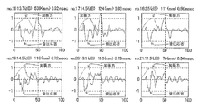
図6に示される6つの波形グラフは、すべて異常部を示す波形である。
波形図中に、丸で囲まれた箇所に、上記(A−1)の特徴である「初期音圧応答における正の微小ピークの存在」が現れていることが分かる。
The six waveform graphs shown in FIG. 6 are all waveforms that indicate abnormal portions.
It can be seen that in the waveform diagram, the “existence of a positive minute peak in the initial sound pressure response”, which is the characteristic of the above (A-1), appears in a circled portion.
図7に示される6つの波形グラフは、すべて異常部を示す波形である。
上記(A−2)の特徴である「加振周波数以上の高周波数成分の卓越あるいは2次発生振動に基づく高周波数成分の存在」が現れていることが分かる。
The six waveform graphs shown in FIG. 7 are all waveforms that indicate abnormal portions.
It can be seen that the feature (A-2), “existence of high frequency components higher than the excitation frequency or presence of high frequency components based on secondary generated vibration” appears.
1 打撃手段
2 加振力検出器・アンプ
3 受音手段
31 マイクロホン
32 フード部材
4 音圧検出器・アンプ
5 AD変換器
6 コンピュータ
7 被測定対象
71 コンクリート部分
72 鋼材等のコンクリート以外の部分
DESCRIPTION OF
Claims (4)
前記加振力の時間特性波形と、前記音圧応答の時間特性波形とを比較することにより診断する方法であって、
加振力の正符号を、前記打撃手段の打撃接触面に圧縮力が働く方向とし、音圧応答の正符号を、静止圧より高い圧力の方向とした場合に、
(A−1)被測定対象に加振力が働いている間又はこれの後続過程において、音圧応答の絶対値が、受音系システムに暗騒音以上の音圧を感知したか否かを区別する閾値である規定値を初めて超えたとき、その符号の正負を観察し、該音圧応答の符号が正であること、
(A−2)被測定対象に加振力が働いている間において、加振周波数以上の高周波数成分が、音圧応答に表れること、
のうち、上記(A−1)、(A−2)の少なくとも1つの現象が観察された場合に、前記被測定対象に異常があると診断することを特徴とするコンクリート系構造物の品質診断方法。 The concrete structure to be measured is struck by any striking means such as an impact hammer, the excitation force obtained from the striking means, and the sound receiving system installed at a position close to the striking location. In a method for diagnosing the quality of a concrete structure by measuring the sound pressure response obtained by the sound receiving means,
A method of making a diagnosis by comparing a time characteristic waveform of the excitation force and a time characteristic waveform of the sound pressure response,
When the positive sign of the excitation force is the direction in which the compressive force acts on the striking contact surface of the striking means, and the positive sign of the sound pressure response is the direction of pressure higher than the static pressure,
(A-1) Whether or not the absolute value of the sound pressure response senses a sound pressure higher than background noise in the sound receiving system while the excitation force is acting on the object to be measured or in the subsequent process. When the specified value, which is a threshold value to be distinguished, is exceeded for the first time, the sign of the sign is observed, and the sign of the sound pressure response is positive,
(A-2) While the excitation force is acting on the object to be measured, a high frequency component higher than the excitation frequency appears in the sound pressure response.
Among these, when at least one phenomenon of the above (A-1) and (A-2) is observed, it is diagnosed that there is an abnormality in the object to be measured. Method.
(B−2)音圧応答の時間特性波形における負の最大値が生じる時刻が、加振力の時間特性波形における最大値が生じる時刻よりも遅れて生じること、
(B−3)音圧応答の時間特性波形の最初の立ち上がりが、加振力の時間特性波形の最初の立ち上がりよりも遅れて生じること、
のうち、上記(B−1)〜(B−3)の少なくとも1つの現象が観察された場合に、被測定対象が健全であると診断することを特徴とする請求項1又は2に記載のコンクリート系構造物の品質診断方法。 (B-1) A sine half wave in which the time characteristic waveform of the excitation force has a sine half wave shape, and the time characteristic waveform of the sound pressure response is obtained by inverting the sign of the waveform indicating the time characteristic of the excitation force. Have a shape,
(B-2) the time at which the negative maximum value in the time characteristic waveform of the sound pressure response occurs is delayed from the time at which the maximum value in the time characteristic waveform of the excitation force occurs;
(B-3) The first rise of the time characteristic waveform of the sound pressure response occurs later than the first rise of the time characteristic waveform of the excitation force.
3. The diagnosis according to claim 1, wherein the measurement target is healthy when at least one phenomenon of (B-1) to (B-3) is observed. Quality diagnosis method for concrete structures.
(C−1)コンクリート系構造物の一部が剥離した状態、
(C−2)コンクリート系構造物の内部に空洞が存在する状態、
(C−3)コンクリート系構造物の内部あるいは内部から外部につながるひび割れが存在する状態、
(C−4)コンクリートの打設時の型枠への充填不足による空洞が存在する状態、
(C−5)コンクリート系構造物の母材に対して他の比較的薄い材料が、(1)規定の接着状態ではなく、剥離的特性を有している状態、及び/又は(2)ひび割れや空洞などを有する状態、
のうち、上記(C−1)〜(C−5)の少なくとも1つの状態であることを特徴とする請求項1〜3のいずれかに記載のコンクリート系構造物の品質診断方法。 The abnormality of the measurement target diagnosed by the quality diagnostic method for a concrete structure according to any one of claims 1 to 3,
(C-1) A state in which a part of the concrete structure is peeled off,
(C-2) A state in which a cavity exists inside the concrete structure,
(C-3) A state in which there is a crack leading from the inside to the outside of the concrete structure,
(C-4) A state in which there is a cavity due to insufficient filling of the formwork when placing concrete,
(C-5) The other relatively thin material with respect to the base material of the concrete-based structure is (1) not in the prescribed adhesion state, but in a state of having peeling properties, and / or (2) cracking Or having a cavity,
The method for diagnosing quality of a concrete structure according to any one of claims 1 to 3, wherein at least one of the states (C-1) to (C-5) is included.
Priority Applications (1)
| Application Number | Priority Date | Filing Date | Title |
|---|---|---|---|
| JP2011029377A JP5666334B2 (en) | 2011-02-15 | 2011-02-15 | Quality diagnosis method for concrete structures |
Applications Claiming Priority (1)
| Application Number | Priority Date | Filing Date | Title |
|---|---|---|---|
| JP2011029377A JP5666334B2 (en) | 2011-02-15 | 2011-02-15 | Quality diagnosis method for concrete structures |
Publications (2)
| Publication Number | Publication Date |
|---|---|
| JP2012168022A true JP2012168022A (en) | 2012-09-06 |
| JP5666334B2 JP5666334B2 (en) | 2015-02-12 |
Family
ID=46972331
Family Applications (1)
| Application Number | Title | Priority Date | Filing Date |
|---|---|---|---|
| JP2011029377A Active JP5666334B2 (en) | 2011-02-15 | 2011-02-15 | Quality diagnosis method for concrete structures |
Country Status (1)
| Country | Link |
|---|---|
| JP (1) | JP5666334B2 (en) |
Cited By (7)
| Publication number | Priority date | Publication date | Assignee | Title |
|---|---|---|---|---|
| WO2015145914A1 (en) * | 2014-03-28 | 2015-10-01 | 日本電気株式会社 | Anchor-bolt evaluation system, and method and program for use therein |
| JP2016205900A (en) * | 2015-04-17 | 2016-12-08 | 株式会社フジタ | State evaluation apparatus for inspection object |
| JP2017089102A (en) * | 2015-11-02 | 2017-05-25 | 学校法人日本大学 | System and program for determining road deterioration |
| JP2018179881A (en) * | 2017-04-19 | 2018-11-15 | 株式会社NejiLaw | Building monitoring system and building monitoring method |
| CN111272646A (en) * | 2018-12-05 | 2020-06-12 | 罗伯特·博世有限公司 | Method and device for testing fiber composite components |
| JP2021096197A (en) * | 2019-12-19 | 2021-06-24 | 中日本ハイウェイ・エンジニアリング東京株式会社 | Concrete structure interior situation checking method, and system using the same |
| JP7489638B2 (en) | 2020-05-20 | 2024-05-24 | 株式会社Kjtd | Non-destructive testing equipment |
Citations (9)
| Publication number | Priority date | Publication date | Assignee | Title |
|---|---|---|---|---|
| JPH02212734A (en) * | 1988-11-30 | 1990-08-23 | Gp Taurio Inc A Wholly Owned Subsidiary Of General Physics Corp | Apparatus and method for detecting change in structual integrity of structural member |
| JPH063336A (en) * | 1992-06-17 | 1994-01-11 | Kumagai Gumi Co Ltd | Method for detecting separation of wall finish of building |
| JP2001311724A (en) * | 2000-04-28 | 2001-11-09 | Sato Kogyo Co Ltd | Concrete soundness determination method and device |
| WO2002018927A1 (en) * | 2000-08-28 | 2002-03-07 | Mitsubishi Denki Kabushiki Kaisha | Structure inspection device |
| JP2004069301A (en) * | 2002-08-01 | 2004-03-04 | Kazuya Mori | Acoustic inspection method and acoustic inspection device |
| JP2005227196A (en) * | 2004-02-16 | 2005-08-25 | Akebono Brake Ind Co Ltd | Peeling inspection method and peeling inspection device |
| JP2006215049A (en) * | 2006-04-27 | 2006-08-17 | Mitsubishi Electric Corp | Structure inspection device |
| JP2009041978A (en) * | 2007-08-07 | 2009-02-26 | Applied Research Kk | Integrity diagnostic method by tap tone analysis |
| JP2010060286A (en) * | 2008-09-01 | 2010-03-18 | Sato Kogyo Co Ltd | Method for discriminating quality classification of structure |
-
2011
- 2011-02-15 JP JP2011029377A patent/JP5666334B2/en active Active
Patent Citations (9)
| Publication number | Priority date | Publication date | Assignee | Title |
|---|---|---|---|---|
| JPH02212734A (en) * | 1988-11-30 | 1990-08-23 | Gp Taurio Inc A Wholly Owned Subsidiary Of General Physics Corp | Apparatus and method for detecting change in structual integrity of structural member |
| JPH063336A (en) * | 1992-06-17 | 1994-01-11 | Kumagai Gumi Co Ltd | Method for detecting separation of wall finish of building |
| JP2001311724A (en) * | 2000-04-28 | 2001-11-09 | Sato Kogyo Co Ltd | Concrete soundness determination method and device |
| WO2002018927A1 (en) * | 2000-08-28 | 2002-03-07 | Mitsubishi Denki Kabushiki Kaisha | Structure inspection device |
| JP2004069301A (en) * | 2002-08-01 | 2004-03-04 | Kazuya Mori | Acoustic inspection method and acoustic inspection device |
| JP2005227196A (en) * | 2004-02-16 | 2005-08-25 | Akebono Brake Ind Co Ltd | Peeling inspection method and peeling inspection device |
| JP2006215049A (en) * | 2006-04-27 | 2006-08-17 | Mitsubishi Electric Corp | Structure inspection device |
| JP2009041978A (en) * | 2007-08-07 | 2009-02-26 | Applied Research Kk | Integrity diagnostic method by tap tone analysis |
| JP2010060286A (en) * | 2008-09-01 | 2010-03-18 | Sato Kogyo Co Ltd | Method for discriminating quality classification of structure |
Cited By (9)
| Publication number | Priority date | Publication date | Assignee | Title |
|---|---|---|---|---|
| WO2015145914A1 (en) * | 2014-03-28 | 2015-10-01 | 日本電気株式会社 | Anchor-bolt evaluation system, and method and program for use therein |
| US10261052B2 (en) | 2014-03-28 | 2019-04-16 | Nec Corporation | Anchor bolt diagnosing system, method of the same, and program of the same |
| JP2016205900A (en) * | 2015-04-17 | 2016-12-08 | 株式会社フジタ | State evaluation apparatus for inspection object |
| JP2017089102A (en) * | 2015-11-02 | 2017-05-25 | 学校法人日本大学 | System and program for determining road deterioration |
| JP2018179881A (en) * | 2017-04-19 | 2018-11-15 | 株式会社NejiLaw | Building monitoring system and building monitoring method |
| CN111272646A (en) * | 2018-12-05 | 2020-06-12 | 罗伯特·博世有限公司 | Method and device for testing fiber composite components |
| CN111272646B (en) * | 2018-12-05 | 2023-09-22 | 罗伯特·博世有限公司 | Method and device for testing a fibre composite component |
| JP2021096197A (en) * | 2019-12-19 | 2021-06-24 | 中日本ハイウェイ・エンジニアリング東京株式会社 | Concrete structure interior situation checking method, and system using the same |
| JP7489638B2 (en) | 2020-05-20 | 2024-05-24 | 株式会社Kjtd | Non-destructive testing equipment |
Also Published As
| Publication number | Publication date |
|---|---|
| JP5666334B2 (en) | 2015-02-12 |
Similar Documents
| Publication | Publication Date | Title |
|---|---|---|
| JP5666334B2 (en) | Quality diagnosis method for concrete structures | |
| WO2010130144A1 (en) | System, device for structural damage detection and method for structural damage detection | |
| JP3340702B2 (en) | A method for measuring deterioration of a concrete structure and a measuring device therefor. | |
| JP5208625B2 (en) | How to determine the quality type of a structure | |
| JP6396076B2 (en) | Detection method and non-contact acoustic detection system using sound waves | |
| CN111487315A (en) | Audio frequency nondestructive testing method for tunnel lining thickness and void | |
| JP2010271116A (en) | Blow hammer for diagnosis of integrity, and method for diagnosis of integrity in concrete structure using the same | |
| JP3456965B2 (en) | Structure inspection method and apparatus | |
| JP6130778B2 (en) | Method and apparatus for inspecting interface of composite structure | |
| JP5714930B2 (en) | Quality diagnosis method for concrete structures | |
| JP2001311724A (en) | Concrete soundness determination method and device | |
| KR101027069B1 (en) | Evaluation method for bonding state of shotcrete | |
| JP2002055089A (en) | Apparatus and method for diagnosing of tunnel | |
| JP6061767B2 (en) | Method and apparatus for exploring delamination inside concrete | |
| JP2019174131A (en) | Concrete void detection device and detection method | |
| JP5450177B2 (en) | Nondestructive inspection method and nondestructive inspection device for grout filling degree | |
| JP3922459B2 (en) | Separation and cavity detection method and apparatus by percussion method | |
| JP3510835B2 (en) | Deterioration measurement device for concrete structures. | |
| JPH0980033A (en) | Judgment method for exfoliation of wall tile from building | |
| JP6128432B2 (en) | Anchor soundness inspection device and anchor soundness inspection method | |
| JP2002148244A (en) | Concrete structure examining and diagnosing method | |
| JP2001124744A (en) | Inspection apparatus for concrete structure | |
| JP2003014709A (en) | Defect probing method for concrete due to strike based on attenuation of energy | |
| JP4596147B2 (en) | Nondestructive inspection method for existing piles | |
| JP2004144586A (en) | Integrity diagnostic method of concrete-based structure |
Legal Events
| Date | Code | Title | Description |
|---|---|---|---|
| A621 | Written request for application examination |
Free format text: JAPANESE INTERMEDIATE CODE: A621 Effective date: 20131003 |
|
| A977 | Report on retrieval |
Free format text: JAPANESE INTERMEDIATE CODE: A971007 Effective date: 20140311 |
|
| A131 | Notification of reasons for refusal |
Free format text: JAPANESE INTERMEDIATE CODE: A131 Effective date: 20140930 |
|
| A521 | Written amendment |
Free format text: JAPANESE INTERMEDIATE CODE: A523 Effective date: 20141110 |
|
| TRDD | Decision of grant or rejection written | ||
| A01 | Written decision to grant a patent or to grant a registration (utility model) |
Free format text: JAPANESE INTERMEDIATE CODE: A01 Effective date: 20141209 |
|
| A61 | First payment of annual fees (during grant procedure) |
Free format text: JAPANESE INTERMEDIATE CODE: A61 Effective date: 20141210 |
|
| R150 | Certificate of patent or registration of utility model |
Ref document number: 5666334 Country of ref document: JP Free format text: JAPANESE INTERMEDIATE CODE: R150 |