JP2012167644A - Fuel injection control apparatus - Google Patents
Fuel injection control apparatus Download PDFInfo
- Publication number
- JP2012167644A JP2012167644A JP2011031017A JP2011031017A JP2012167644A JP 2012167644 A JP2012167644 A JP 2012167644A JP 2011031017 A JP2011031017 A JP 2011031017A JP 2011031017 A JP2011031017 A JP 2011031017A JP 2012167644 A JP2012167644 A JP 2012167644A
- Authority
- JP
- Japan
- Prior art keywords
- injection
- waveform
- pressure
- fuel
- learning
- Prior art date
- Legal status (The legal status is an assumption and is not a legal conclusion. Google has not performed a legal analysis and makes no representation as to the accuracy of the status listed.)
- Granted
Links
Images


Classifications
-
- F—MECHANICAL ENGINEERING; LIGHTING; HEATING; WEAPONS; BLASTING
- F02—COMBUSTION ENGINES; HOT-GAS OR COMBUSTION-PRODUCT ENGINE PLANTS
- F02D—CONTROLLING COMBUSTION ENGINES
- F02D41/00—Electrical control of supply of combustible mixture or its constituents
- F02D41/30—Controlling fuel injection
- F02D41/38—Controlling fuel injection of the high pressure type
- F02D41/3809—Common rail control systems
- F02D41/3836—Controlling the fuel pressure
- F02D41/3863—Controlling the fuel pressure by controlling the flow out of the common rail, e.g. using pressure relief valves
-
- F—MECHANICAL ENGINEERING; LIGHTING; HEATING; WEAPONS; BLASTING
- F02—COMBUSTION ENGINES; HOT-GAS OR COMBUSTION-PRODUCT ENGINE PLANTS
- F02D—CONTROLLING COMBUSTION ENGINES
- F02D41/00—Electrical control of supply of combustible mixture or its constituents
- F02D41/24—Electrical control of supply of combustible mixture or its constituents characterised by the use of digital means
- F02D41/2406—Electrical control of supply of combustible mixture or its constituents characterised by the use of digital means using essentially read only memories
- F02D41/2425—Particular ways of programming the data
- F02D41/2429—Methods of calibrating or learning
- F02D41/2451—Methods of calibrating or learning characterised by what is learned or calibrated
- F02D41/2464—Characteristics of actuators
- F02D41/2467—Characteristics of actuators for injectors
-
- F—MECHANICAL ENGINEERING; LIGHTING; HEATING; WEAPONS; BLASTING
- F02—COMBUSTION ENGINES; HOT-GAS OR COMBUSTION-PRODUCT ENGINE PLANTS
- F02M—SUPPLYING COMBUSTION ENGINES IN GENERAL WITH COMBUSTIBLE MIXTURES OR CONSTITUENTS THEREOF
- F02M47/00—Fuel-injection apparatus operated cyclically with fuel-injection valves actuated by fluid pressure
- F02M47/02—Fuel-injection apparatus operated cyclically with fuel-injection valves actuated by fluid pressure of accumulator-injector type, i.e. having fuel pressure of accumulator tending to open, and fuel pressure in other chamber tending to close, injection valves and having means for periodically releasing that closing pressure
- F02M47/027—Electrically actuated valves draining the chamber to release the closing pressure
-
- F—MECHANICAL ENGINEERING; LIGHTING; HEATING; WEAPONS; BLASTING
- F02—COMBUSTION ENGINES; HOT-GAS OR COMBUSTION-PRODUCT ENGINE PLANTS
- F02M—SUPPLYING COMBUSTION ENGINES IN GENERAL WITH COMBUSTIBLE MIXTURES OR CONSTITUENTS THEREOF
- F02M57/00—Fuel-injectors combined or associated with other devices
- F02M57/005—Fuel-injectors combined or associated with other devices the devices being sensors
-
- F—MECHANICAL ENGINEERING; LIGHTING; HEATING; WEAPONS; BLASTING
- F02—COMBUSTION ENGINES; HOT-GAS OR COMBUSTION-PRODUCT ENGINE PLANTS
- F02D—CONTROLLING COMBUSTION ENGINES
- F02D2200/00—Input parameters for engine control
- F02D2200/02—Input parameters for engine control the parameters being related to the engine
- F02D2200/06—Fuel or fuel supply system parameters
- F02D2200/0602—Fuel pressure
- F02D2200/0604—Estimation of fuel pressure
-
- F—MECHANICAL ENGINEERING; LIGHTING; HEATING; WEAPONS; BLASTING
- F02—COMBUSTION ENGINES; HOT-GAS OR COMBUSTION-PRODUCT ENGINE PLANTS
- F02D—CONTROLLING COMBUSTION ENGINES
- F02D2250/00—Engine control related to specific problems or objectives
- F02D2250/04—Fuel pressure pulsation in common rails
-
- F—MECHANICAL ENGINEERING; LIGHTING; HEATING; WEAPONS; BLASTING
- F02—COMBUSTION ENGINES; HOT-GAS OR COMBUSTION-PRODUCT ENGINE PLANTS
- F02M—SUPPLYING COMBUSTION ENGINES IN GENERAL WITH COMBUSTIBLE MIXTURES OR CONSTITUENTS THEREOF
- F02M63/00—Other fuel-injection apparatus having pertinent characteristics not provided for in groups F02M39/00 - F02M57/00 or F02M67/00; Details, component parts, or accessories of fuel-injection apparatus, not provided for in, or of interest apart from, the apparatus of groups F02M39/00 - F02M61/00 or F02M67/00; Combination of fuel pump with other devices, e.g. lubricating oil pump
- F02M63/0012—Valves
- F02M63/0031—Valves characterized by the type of valves, e.g. special valve member details, valve seat details, valve housing details
- F02M63/0045—Three-way valves
Abstract
Description
本発明は、内燃機関の燃料噴射弁から燃料を噴射させることに伴い生じる燃料圧力の変化を燃圧センサで検出し、検出した圧力波形から算出される噴射率パラメータに基づき、燃料噴射弁の作動を制御する燃料噴射制御装置に関する。 The present invention detects a change in fuel pressure caused by injecting fuel from a fuel injection valve of an internal combustion engine with a fuel pressure sensor, and operates the fuel injection valve based on an injection rate parameter calculated from the detected pressure waveform. The present invention relates to a fuel injection control device to be controlled.
内燃機関の出力トルク及びエミッション状態を精度良く制御するには、燃料噴射弁から噴射される燃料の噴射量及び噴射開始時期等、その噴射状態を精度良く制御することが重要である。 In order to accurately control the output torque and the emission state of the internal combustion engine, it is important to accurately control the injection state such as the injection amount of fuel injected from the fuel injection valve and the injection start timing.
そこで特許文献1,2等には、コモンレールの吐出口から燃料噴射弁の噴孔に至るまでの燃料供給経路内で噴射に伴い生じる燃料圧力の変化を燃圧センサで検出している。燃圧センサにより検出される圧力の波形(圧力波形)は、時間に対する噴射率の変化を表す波形(噴射率波形)と相関が高いため、圧力波形に基づけば噴射率波形(噴射状態)を推定できる。したがって、圧力波形を検出すれば実際の噴射状態を学習することができ、この学習値に基づき次回からの噴射指令信号を設定することで、噴射状態を所望する状態に精度良く制御することを図っている。
Therefore, in
上記学習の内容に関し、本発明者は次のように検討した。すなわち、噴射率波形を特定するのに要する各種の噴射率パラメータを、圧力波形から算出して学習する。噴射率パラメータの具体例としては、噴射率の上昇速度Rαや下降速度Rβ、噴射開始遅れ時間td、噴射終了遅れ時間te、最大噴射率Rmax等が挙げられる(図2参照)。 The present inventor considered the contents of the learning as follows. That is, various injection rate parameters required for specifying the injection rate waveform are calculated from the pressure waveform and learned. Specific examples of the injection rate parameter include an injection rate rising speed Rα and a falling speed Rβ, an injection start delay time td, an injection end delay time te, and a maximum injection rate Rmax (see FIG. 2).
また、これらの噴射率パラメータは、その都度の噴射量に応じて異なる値となるため、噴射量と関連付けて学習させることを本発明者は検討した。そして、現時点で要求されている噴射量に対応した噴射率パラメータの値を、前記学習値を線形補間することで取得し、取得した噴射率パラメータに基づき噴射指令信号を設定する。 Moreover, since these injection rate parameters become different values according to the injection amount in each case, the present inventor has studied to learn in association with the injection amount. And the value of the injection rate parameter corresponding to the injection amount currently requested | required is acquired by linearly interpolating the said learning value, and an injection command signal is set based on the acquired injection rate parameter.
しかし、本発明者が各種試験を実施したところ、噴射量と噴射率パラメータとの関係は単純な比例関係ではなく、図6(c)(d)に例示する如く周期的に変化することが明らかとなった。そのため、上述の線形補間により得られた噴射率パラメータを用いて噴射指令信号を設定すると、噴射状態を所望の状態に精度良く制御できなくなる、といった課題を本発明者は見出した。 However, when the present inventor conducted various tests, it is clear that the relationship between the injection amount and the injection rate parameter is not a simple proportional relationship and changes periodically as illustrated in FIGS. 6C and 6D. It became. For this reason, the present inventor has found that when the injection command signal is set using the injection rate parameter obtained by the linear interpolation described above, the injection state cannot be accurately controlled to a desired state.
本発明は、上記課題を解決するためになされたものであり、その目的は、燃料の噴射状態を高精度で制御できる燃料噴射制御装置を提供することにある。 The present invention has been made to solve the above problems, and an object of the present invention is to provide a fuel injection control device capable of controlling the fuel injection state with high accuracy.
以下、上記課題を解決するための手段、及びその作用効果について記載する。 Hereinafter, means for solving the above-described problems and the operation and effects thereof will be described.
請求項1記載の発明では、内燃機関で燃焼させる燃料を噴孔から噴射する燃料噴射弁と、前記噴孔から燃料を噴射させることに伴い前記噴孔に至るまでの燃料供給経路内の燃料圧力を検出する燃圧センサと、を備えた燃料噴射システムに適用されることを前提とする。 According to the first aspect of the present invention, a fuel injection valve that injects fuel to be burned in an internal combustion engine from an injection hole, and a fuel pressure in a fuel supply path that reaches the injection hole as fuel is injected from the injection hole It is assumed that the present invention is applied to a fuel injection system including a fuel pressure sensor for detecting
そして、前記燃圧センサの検出値に基づき、燃料噴射に伴い生じた圧力変化を表す圧力波形を取得する圧力波形取得手段と、噴射率波形を特定するのに要する噴射率パラメータを、前記圧力波形に基づき算出する噴射率パラメータ算出手段と、算出した前記噴射率パラメータを、噴射量と関連付けた学習値として記憶するパラメータ学習手段と、前記噴射量の変化に伴い生じる前記学習値の周期的な変化を表した学習うねり波形を、前記圧力波形に含まれる圧力うねり成分に基づき推定する学習うねり波形推定手段と、要求噴射量に対応する前記噴射率パラメータの値を、前記学習うねり波形を用いて前記学習値を補間して算出する補間手段と、を備えることを特徴とする。 Then, based on the detection value of the fuel pressure sensor, a pressure waveform acquisition means for acquiring a pressure waveform representing a pressure change caused by fuel injection, and an injection rate parameter required for specifying the injection rate waveform are included in the pressure waveform. Injection rate parameter calculation means to calculate based on, parameter learning means to store the calculated injection rate parameter as a learning value associated with the injection amount, and periodic change of the learning value caused by the change of the injection amount The learning waviness waveform estimating means for estimating the represented learning waviness waveform based on the pressure waviness component included in the pressure waveform, and the value of the injection rate parameter corresponding to the required injection amount using the learning waviness waveform Interpolating means for interpolating values to calculate.
噴射率パラメータと噴射量との関係は単純な比例関係ではなく、図6(c)(d)に例示する如く周期的に変化する学習うねり波形となることは先述した通りである。そして本発明者は、前記学習うねり波形が、圧力波形中に現れる圧力うねり成分(図6(b)参照)と相関があることを見出した。具体的には、学習うねり波形と圧力うねり成分とでは、うねりの周期、振幅、減衰率等について相関がある(図6参照)。 As described above, the relationship between the injection rate parameter and the injection amount is not a simple proportional relationship, and becomes a learning undulation waveform that periodically changes as illustrated in FIGS. The present inventor has found that the learning wave waveform correlates with a pressure wave component (see FIG. 6B) appearing in the pressure waveform. Specifically, the learning swell waveform and the pressure swell component are correlated with the swell period, amplitude, attenuation rate, and the like (see FIG. 6).
この点を鑑みた上記発明では、圧力うねり成分に基づき学習うねり波形を推定し、推定した学習うねり波形を用いて学習値を補間して要求噴射量に対応する噴射率パラメータの値を算出するので、学習値を線形補間して算出した噴射率パラメータに基づき噴射指令信号を設定する場合に比べて、燃料の噴射状態を高精度で制御できる。 In the above-mentioned invention in view of this point, the learning swell waveform is estimated based on the pressure swell component, and the learning value is interpolated using the estimated learning swell waveform to calculate the value of the injection rate parameter corresponding to the required injection amount. Compared to the case where the injection command signal is set based on the injection rate parameter calculated by linearly interpolating the learning value, the fuel injection state can be controlled with higher accuracy.
請求項2記載の発明では、前記圧力うねり成分は、前記圧力波形のうち、噴射率上昇に伴い生じる圧力下降が停止してから、噴射率下降に伴い生じる圧力上昇が停止するまでの部分から抽出した波形であることを特徴とする。 According to a second aspect of the present invention, the pressure swell component is extracted from a portion of the pressure waveform from when the pressure decrease caused by the increase in the injection rate stops until the pressure increase caused by the decrease in the injection rate stops. It is characterized by having a waveform.
ここで、圧力うねり成分の発生メカニズムについて説明すると、噴孔近傍で生じた圧力変化が脈動となって燃料供給経路を伝播し、いずれかの部位でその脈動が反射して伝播していく。そのため、このような脈動は燃圧センサへ周期的に伝播されてくることとなり、その脈動を燃圧センサが検出することに起因して圧力うねり成分は生じる。 Here, the generation mechanism of the pressure swell component will be described. The pressure change generated in the vicinity of the injection hole becomes a pulsation and propagates through the fuel supply path, and the pulsation is reflected and propagated at any part. Therefore, such pulsation is periodically propagated to the fuel pressure sensor, and a pressure swell component is generated due to the fuel pressure sensor detecting the pulsation.
この圧力うねり成分は、以下に説明する前段うねり成分Wcと自うねり成分Wdとに分類できることを本発明者は考察した。すなわち、前段うねり成分Wcとは、図2(c)および図6(b)に例示するように多段噴射時における前段噴射の影響により生じたものである。この前段うねり成分Wcは、今回の噴射にかかる圧力波形の全体に重畳するものであり、前段の噴射状態に基づき推測して、推測した前段うねり成分Wcを今回の噴射にかかる圧力波形から差し引けば除去できる。 The present inventor considered that the pressure swell component can be classified into a pre-swell component Wc and a self-swell component Wd described below. That is, the pre-stage swell component Wc is generated by the influence of the pre-stage injection at the time of multi-stage injection, as illustrated in FIGS. 2 (c) and 6 (b). The preceding swell component Wc is superimposed on the entire pressure waveform applied to the current injection, and is estimated based on the previous injection state, and the estimated previous swell component Wc is subtracted from the pressure waveform applied to the current injection. Can be removed.
一方、自うねり成分Wdとは、図6(b)に例示するように自身の噴射の影響により生じた圧力うねり成分であり、噴射率上昇に伴い生じる自噴射の圧力下降により生じた脈動に起因して生じたものである。したがって、この自うねり成分Wdについては推定が困難であり、圧力波形から差し引いて除去することも困難である。 On the other hand, the self-swelling component Wd is a pressure swelling component generated by the influence of its own injection as illustrated in FIG. 6B, and is caused by the pulsation caused by the pressure drop of the self-injection caused by the increase in the injection rate. This is what happened. Therefore, it is difficult to estimate the self-swelling component Wd, and it is difficult to remove it by subtracting it from the pressure waveform.
この点を鑑みた上記発明では、噴射率上昇に伴い生じる圧力下降が停止した以降の部分から抽出した波形(つまり自うねり成分Wd)を学習うねり波形推定手段による推定の対象とするので、除去が困難な自うねり成分の影響を加味した噴射率パラメータを補間により取得できるので、燃料の噴射状態を高精度で制御できる。 In the above-mentioned invention in view of this point, the waveform extracted from the portion after the pressure drop caused by the increase in the injection rate is stopped (that is, the self-swelling component Wd) is the target of estimation by the learning swell waveform estimating means, and therefore the removal is performed. Since the injection rate parameter taking into account the influence of difficult self-swelling components can be obtained by interpolation, the fuel injection state can be controlled with high accuracy.
請求項3記載の発明では、前記噴射率パラメータの1つは、前記噴射率波形のうち前記燃料噴射弁の閉弁作動に伴い噴射率が下降する部分の波形を特定するのに要する噴射率パラメータであることを特徴とする。 According to a third aspect of the present invention, one of the injection rate parameters is an injection rate parameter required for specifying a waveform of a portion of the injection rate waveform where the injection rate decreases as the fuel injection valve is closed. It is characterized by being.
上述した自うねり成分による影響は、圧力波形のうち、噴射率上昇に伴い燃圧が上昇する部分には殆ど重畳せず、最大噴射率で噴射する期間および噴射率下降に対応する部分に主に重畳する。この点を鑑みた上記発明では、噴射率下降に関する噴射率パラメータを補間手段による補間の対象とするので、自うねり成分の影響を加味した噴射率パラメータに基づき噴射指令信号を設定することができ、燃料の噴射状態を高精度で制御できる。 The effect of the above-described self-swell component is hardly superimposed on the portion of the pressure waveform where the fuel pressure increases as the injection rate increases, but mainly on the portion corresponding to the period of injection at the maximum injection rate and the decrease in injection rate. To do. In the above invention in view of this point, since the injection rate parameter related to the decrease in the injection rate is an object of interpolation by the interpolation means, it is possible to set the injection command signal based on the injection rate parameter taking into account the influence of the self-swelling component, The fuel injection state can be controlled with high accuracy.
請求項4記載の発明では、前記噴射率パラメータの1つは、前記燃料噴射弁の閉弁作動に伴い噴射率が下降する速度であることを特徴とする。
The invention according to
図6(b)中の符号Wdは、自うねり成分により燃圧センサが変動する様子を示すものであるが、自うねり成分により燃圧が高くなっているタイミング(符号A3参照)で、噴射率下降に伴う圧力上昇を開始させるような噴射の場合には、燃料噴射弁が備える弁体の閉弁作動速度が遅くなることに起因して、圧力波形の上昇速度(噴射率の下降速度)が遅くなる。一方、自うねり成分により燃圧が低くなっているタイミング(符号A2参照)で、噴射率下降に伴う圧力上昇が開始した場合には、前記弁体の閉弁作動速度が前記A3のタイミングで圧力上昇する場合に比べて、圧力波形の上昇速度(噴射率の下降速度)が速くなる。 The symbol Wd in FIG. 6B shows how the fuel pressure sensor fluctuates due to the self-swelling component, but the injection rate decreases at the timing when the fuel pressure increases due to the self-swelling component (see symbol A3). In the case of injection that starts the accompanying pressure increase, the pressure waveform rising speed (injection rate decreasing speed) becomes slow due to the slowing of the valve closing operation speed of the valve body provided in the fuel injection valve. . On the other hand, when the pressure increase accompanying the decrease in the injection rate starts at the timing when the fuel pressure is lowered due to the self-swelling component (see symbol A2), the valve closing operation speed of the valve body increases at the timing of A3. Compared with the case where the pressure waveform is increased, the pressure waveform increase speed (injection rate decrease speed) is increased.
このように、噴射率下降速度は自うねり成分の影響を大きく受けるので、このような噴射率下降速度を噴射率パラメータの1つとして、学習うねり波形を用いた補間を実施する上記発明によれば、自うねり成分の影響を加味して補間することによる噴射精度向上の効果が好適に発揮される。 As described above, since the injection rate lowering speed is greatly affected by the self-swelling component, according to the above-described invention in which interpolation is performed using the learning swell waveform with such an injection rate lowering speed as one of the injection rate parameters. The effect of improving the injection accuracy by interpolating in consideration of the influence of the self-swelling component is suitably exhibited.
請求項5記載の発明では、前記噴射率パラメータの1つは、前記燃料噴射弁へ閉弁を指令してから前記燃料噴射弁が閉弁作動を開始するまでの遅れ時間であることを特徴とする。 The invention according to claim 5 is characterized in that one of the injection rate parameters is a delay time from when the fuel injection valve is instructed to close, to when the fuel injection valve starts the valve closing operation. To do.
自うねり成分により燃圧が高くなっているタイミング(図6(a)中の符号A3参照)で、噴射率下降に伴う圧力上昇を開始させるような噴射の場合には、閉弁を指令してから燃料噴射弁が閉弁作動を開始するまでの遅れ時間が長くなる。一方、自うねり成分により燃圧が低くなっているタイミング(符号A2参照)で、噴射率下降に伴う圧力上昇を開始させるような噴射の場合には、前記遅れ時間は短くなる。 In the case of injection that starts the pressure increase accompanying the decrease in the injection rate at the timing when the fuel pressure is increased due to the self-swelling component (see symbol A3 in FIG. 6A), the valve closing is instructed. The delay time until the fuel injection valve starts the valve closing operation becomes longer. On the other hand, in the case of the injection in which the pressure increase accompanying the decrease in the injection rate is started at the timing when the fuel pressure is lowered due to the self-swelling component (see symbol A2), the delay time is shortened.
このように、燃料噴射弁へ閉弁を指令してから閉弁作動を開始するまでの遅れ時間は自うねり成分の影響を大きく受けるので、このような閉弁の遅れ時間を噴射率パラメータの1つとして、学習うねり波形を用いた補間を実施する上記発明によれば、自うねり成分の影響を加味して補間することによる噴射精度向上の効果が好適に発揮される。 As described above, since the delay time from when the fuel injection valve is instructed to close to the start of the valve closing operation is greatly influenced by the self-swelling component, such valve closing delay time is set to 1 of the injection rate parameter. As described above, according to the above-described invention in which the interpolation using the learning undulation waveform is performed, the effect of improving the injection accuracy by interpolating in consideration of the influence of the self-swelling component is suitably exhibited.
請求項6記載の発明では、前記学習うねり波形推定手段は、推定した前記学習うねり波形を、噴射開始時における前記燃料噴射弁への燃料供給圧力と関連付けて学習し、前記補間手段は、現時点での前記燃料供給圧力に対応する前記学習うねり波形を用いて前記補間を行うことを特徴とする。 In the invention according to claim 6, the learning undulation waveform estimation means learns the estimated learning undulation waveform in association with the fuel supply pressure to the fuel injection valve at the start of injection, and the interpolation means The interpolation is performed using the learning swell waveform corresponding to the fuel supply pressure.
ここで、噴射率パラメータは、噴射指令信号が同じであってもその時の燃料供給圧力に応じて異なる値となる。この点を鑑みた上記発明によれば、推定した学習うねり波形を燃料供給圧力と関連付けて学習し、現時点での燃料供給圧力に対応する学習うねり波形を用いて補間して噴射率パラメータを算出するので、噴射指令信号の設定に用いる噴射率パラメータを高精度で算出でき、燃料の噴射状態を高精度で制御できる。 Here, even if the injection command signal is the same, the injection rate parameter takes a different value depending on the fuel supply pressure at that time. According to the above invention in view of this point, the estimated learning swell waveform is learned in association with the fuel supply pressure, and the injection rate parameter is calculated by interpolation using the learning swell waveform corresponding to the current fuel supply pressure. Therefore, the injection rate parameter used for setting the injection command signal can be calculated with high accuracy, and the fuel injection state can be controlled with high accuracy.
請求項7記載の発明では、前記学習うねり波形推定手段は、前記圧力うねり成分に基づくとともに、前記圧力波形の圧力の積算値にも基づいて前記学習うねり波形を推定することを特徴とする。
The invention according to
学習値が圧力うねり成分の影響を受けて変化することは先述した通りであるが、圧力波形の履歴(圧力の積算値)に応じても以下に例示するように学習値は変化する。 As described above, the learning value changes under the influence of the pressure swell component. However, the learning value also changes according to the pressure waveform history (integrated value of pressure) as illustrated below.
例えば、請求項4記載の如く噴射率が下降する速度を学習値とした場合において、弁体の閉弁作動開始時期(図8(a)中の符号L23参照)が同じ(つまり図6(b)に示す圧力上昇開始時期A2,A3が同じ)であっても、その閉弁作動開始時期の直前での弁体のリフトアップ速度(図8(a)中の符号Lα参照)が速いほど、弁体のリフトアップ慣性力が大きくなるので、噴射率下降速度は遅くなる。そして、前記リフトアップ速度は、閉弁作動開始時期に至るまでの圧力波形の圧力積算値が大きいほど速くなるので、圧力積算値が大きいほど噴射率下降速度(学習値)を遅くすればよい。
For example, when the learning rate is used as the speed at which the injection rate decreases as described in
また、請求項5記載の如く燃料噴射弁が閉弁作動を開始するまでの遅れ時間を学習値とした場合においては、弁体の閉弁作動開始時期L23が同じであっても、その閉弁作動開始時期の直前での弁体のリフトアップ速度が速いほど、弁体のリフトアップ慣性力が大きくなるので、弁体が閉弁作動を開始しにくくなり前記遅れ時間は長くなる。そして、前記リフトアップ速度は、閉弁作動開始時期に至るまでの圧力波形の圧力積算値が大きいほど長くなるので、圧力積算値が大きいほど閉弁に係る遅れ時間(学習値)を長くすればよい。 Further, in the case where the delay time until the fuel injection valve starts the valve closing operation is set as the learned value as described in claim 5, even if the valve element closing operation start timing L23 is the same, the valve closing operation is performed. The higher the lift-up speed of the valve body immediately before the operation start timing, the higher the lift-up inertia force of the valve body, so that the valve body is less likely to start the valve closing operation, and the delay time becomes longer. The lift-up speed becomes longer as the pressure integrated value of the pressure waveform until the valve closing operation start timing is larger. Therefore, if the pressure integrated value is larger, the delay time (learning value) related to valve closing is lengthened. Good.
以上に例示する如く、圧力波形の圧力積算値に応じて学習値が変化することに着目し、上記発明では、圧力波形の圧力の積算値に基づき学習うねり波形を推定するので、学習うねり波形の推定精度を向上できる。 Focusing on the fact that the learning value changes according to the pressure integrated value of the pressure waveform, as exemplified above, the learning undulation waveform is estimated based on the integrated value of the pressure waveform pressure. The estimation accuracy can be improved.
圧力積算値に基づき学習うねり波形を推定する具体例としては、図8(d)中の実線Wgと点線Wg1にて比較される如く、学習うねり波形の位相を遅角させる遅角量(図8(d)中の符号ga参照)を圧力積算値に応じて調節する。また、図8(d)中の実線Wgと一点鎖線Wg2にて比較される如く、学習うねり波形の値を高くさせるオフセット量(図8(d)中の符号gb参照)を圧力積算値に応じて調節することが挙げられる。 As a specific example of estimating the learning undulation waveform based on the integrated pressure value, a retard amount for retarding the phase of the learning undulation waveform as compared with the solid line Wg and the dotted line Wg1 in FIG. (See symbol ga in (d)) is adjusted according to the integrated pressure value. Further, as compared with the solid line Wg and the alternate long and short dash line Wg2 in FIG. 8D, an offset amount (see symbol gb in FIG. 8D) for increasing the value of the learning undulation waveform is determined according to the integrated pressure value. Adjusting.
以下、本発明を具体化した各実施形態を図面に基づいて説明する。なお、以下に説明する燃料噴射制御装置は、車両用のエンジン(内燃機関)に搭載されたものであり、当該エンジンには、複数の気筒#1〜#4について高圧燃料を噴射して圧縮自着火燃焼させるディーゼルエンジンを想定している。
Hereinafter, embodiments embodying the present invention will be described with reference to the drawings. The fuel injection control apparatus described below is mounted on a vehicle engine (internal combustion engine). The engine is injected with high-pressure fuel for a plurality of
(第1実施形態)
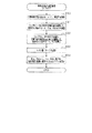
図1は、上記エンジンの各気筒に搭載された燃料噴射弁10、各々の燃料噴射弁10に搭載された燃圧センサ20、及び車両に搭載された電子制御装置であるECU30等を示す模式図である。
(First embodiment)
FIG. 1 is a schematic diagram showing a
先ず、燃料噴射弁10を含むエンジンの燃料噴射システムについて説明する。燃料タンク40内の燃料は、燃料ポンプ41によりコモンレール42(蓄圧容器)に圧送されて蓄圧され、各気筒の燃料噴射弁10(#1〜#4)へ分配供給される。複数の燃料噴射弁10(#1〜#4)は、予め設定された順番で燃料の噴射を順次行う。
First, an engine fuel injection system including the
なお、燃料ポンプ41にはプランジャポンプが用いられているため、プランジャの往復動に同期して燃料は圧送される。そして、当該燃料ポンプ41はエンジン出力を駆動源としてクランク軸により駆動するので、1燃焼サイクル中に決められた回数だけ燃料ポンプ41から燃料を圧送することとなる。
In addition, since the plunger pump is used for the
燃料噴射弁10は、以下に説明するボデー11、ニードル形状の弁体12及びアクチュエータ13等を備えて構成されている。ボデー11は、内部に高圧通路11aを形成するとともに、燃料を噴射する噴孔11bを形成する。弁体12は、ボデー11内に収容されて噴孔11bを開閉する。
The
ボデー11内には弁体12に背圧を付与する背圧室11cが形成されており、高圧通路11a及び低圧通路11dは背圧室11cと接続されている。高圧通路11a及び低圧通路11dと背圧室11cとの連通状態は制御弁14により切り替えられており、電磁コイルやピエゾ素子等のアクチュエータ13へ通電して制御弁14を図1の下方へ押し下げ作動させると、背圧室11cは低圧通路11dと連通して背圧室11c内の燃料圧力は低下する。その結果、弁体12へ付与される背圧力が低下して弁体12はリフトアップ(開弁作動)する。これにより、弁体12のシート面12aがボデー11のシート面11eから離座して、噴孔11bから燃料が噴射される。
A
一方、アクチュエータ13への通電をオフして制御弁14を図1の上方へ作動させると、背圧室11cは高圧通路11aと連通して背圧室11c内の燃料圧力は上昇する。その結果、弁体12へ付与される背圧力が上昇して弁体12はリフトダウン(閉弁作動)する。これにより、弁体12のシート面12aがボデー11のシート面11eに着座して、噴孔11bからの燃料噴射が停止される。
On the other hand, when the power supply to the
したがって、ECU30がアクチュエータ13への通電を制御することで、弁体12の開閉作動が制御される。これにより、コモンレール42から高圧通路11aへ供給された高圧燃料は、弁体12の開閉作動に応じて噴孔11bから噴射される。
Therefore, the
燃圧センサ20は、全ての燃料噴射弁10に搭載されており、以下に説明するステム21(起歪体)及び圧力センサ素子22等を備えて構成されている。ステム21はボデー11に取り付けられており、ステム21に形成されたダイヤフラム部21aが高圧通路11aを流通する高圧燃料の圧力を受けて弾性変形する。圧力センサ素子22はダイヤフラム部21aに取り付けられており、ダイヤフラム部21aで生じた弾性変形量に応じて圧力検出信号をECU30へ出力する。
The
ECU30は、アクセルペダルの操作量やエンジン負荷、エンジン回転速度NE等に基づき目標噴射状態(例えば噴射段数、噴射開始時期、噴射終了時期、噴射量等)を算出する。例えば、エンジン負荷及びエンジン回転速度に対応する最適噴射状態を噴射状態マップにして記憶させておく。そして、現状のエンジン負荷及びエンジン回転速度に基づき、噴射状態マップを参照して目標噴射状態を算出する。そして、算出した目標噴射状態に対応する噴射指令信号t1、t2、Tq(図2(a)参照)を、後に詳述する噴射率パラメータtd,te,Rα,Rβ,Rmaxに基づき設定し、燃料噴射弁10へ出力することで燃料噴射弁10の作動を制御する。
The
次に、燃料噴射弁10から燃料を噴射させる場合における噴射制御の手法について、図2〜図5を用いて以下に説明する。
Next, a method of injection control when fuel is injected from the
燃圧センサ20の検出値に基づき、噴射に伴い生じた燃料圧力の変化を圧力波形(図2(c)参照)として検出し、検出した圧力波形に基づき燃料の時間に対する噴射率の変化を表した噴射率波形(図2(b)参照)を演算して噴射状態を検出する。そして、検出した噴射率波形(噴射状態)を特定する噴射率パラメータRα,Rβ,Rmaxを学習するとともに、噴射指令信号(パルスオン時期t1及びパルスオン期間Tq)と噴射状態との相関関係を特定する噴射率パラメータtd,teを学習する。
Based on the detected value of the
具体的には、圧力波形のうち、噴射開始に伴い燃圧降下を開始する変曲点P1から降下が終了する変曲点P2までの降下波形を、最小二乗法等により直線に近似した降下近似直線Lαを算出する。そして、降下近似直線Lαのうち基準値Bαとなる時期(LαとBαの交点時期LBα)を算出する。この交点時期LBαと噴射開始時期R1とは相関が高いことに着目し、交点時期LBαに基づき噴射開始時期R1を算出する。例えば、交点時期LBαよりも所定の遅れ時間Cαだけ前の時期を噴射開始時期R1として算出すればよい。 Specifically, in the pressure waveform, a descending approximation line that approximates a descending waveform from the inflection point P1 at which the fuel pressure drop starts at the start of injection to the inflection point P2 at which the descent ends by a least square method or the like. Lα is calculated. Then, a time (a crossing time LBα between Lα and Bα) that is the reference value Bα in the descending approximate straight line Lα is calculated. Focusing on the fact that the intersection time LBα and the injection start time R1 are highly correlated, the injection start time R1 is calculated based on the intersection time LBα. For example, a timing that is a predetermined delay time Cα before the intersection timing LBα may be calculated as the injection start timing R1.
また、圧力波形のうち、噴射終了に伴い燃圧上昇を開始する変曲点P3から降下が終了する変曲点P5までの上昇波形を、最小二乗法等により直線に近似した上昇近似直線Lβを算出する。そして、上昇近似直線Lβのうち基準値Bβとなる時期(LβとBβの交点時期LBβ)を算出する。この交点時期LBβと噴射終了時期R4とは相関が高いことに着目し、交点時期LBβに基づき噴射終了時期R4を算出する。例えば、交点時期LBβよりも所定の遅れ時間Cβだけ前の時期を噴射終了時期R4として算出すればよい。 In addition, among the pressure waveforms, a rising approximate line Lβ is calculated by approximating the rising waveform from the inflection point P3 at which the fuel pressure rises at the end of the injection to the inflection point P5 at which the descent ends by a least square method or the like. To do. Then, a time (intersection time LBβ between Lβ and Bβ) that is the reference value Bβ in the rising approximate straight line Lβ is calculated. Focusing on the fact that the intersection timing LBβ and the injection end timing R4 are highly correlated, the injection end timing R4 is calculated based on the intersection timing LBβ. For example, a timing that is a predetermined delay time Cβ before the intersection timing LBβ may be calculated as the injection end timing R4.
次に、降下近似直線Lαの傾きと噴射率増加の傾きとは相関が高いことに着目し、図2(b)に示す噴射率波形のうち噴射増加を示す直線Rαの傾きを、降下近似直線Lαの傾きに基づき算出する。例えば、Lαの傾きに所定の係数を掛けてRαの傾きを算出すればよい。同様にして、上昇近似直線Lβの傾きと噴射率減少の傾きとは相関が高いので、噴射率波形のうち噴射減少を示す直線Rβの傾きを、上昇近似直線Lβの傾きに基づき算出する。 Next, paying attention to the fact that the slope of the descending approximate line Lα and the slope of the injection rate increase are highly correlated, the slope of the straight line Rα indicating the increase in the injection rate waveform shown in FIG. Calculation is based on the slope of Lα. For example, the slope of Rα may be calculated by multiplying the slope of Lα by a predetermined coefficient. Similarly, since the slope of the rising approximate line Lβ and the slope of the injection rate decrease are highly correlated, the slope of the straight line Rβ indicating the decrease in injection in the injection rate waveform is calculated based on the slope of the rising approximate line Lβ.
次に、噴射率波形の直線Rα,Rβに基づき、噴射終了を指令したことに伴い弁体12がリフトダウンを開始する時期(閉弁作動開始時期R23)を算出する。具体的には、両直線Rα,Rβの交点を算出し、その交点時期を閉弁作動開始時期R23として算出する。また、噴射開始時期R1の噴射開始指令時期t1に対する遅れ時間(噴射開始遅れ時間td)を算出する。また、閉弁作動開始時期R23の噴射終了指令時期t2に対する遅れ時間(噴射終了遅れ時間te)を算出する。
Next, based on the straight lines Rα and Rβ of the injection rate waveform, a timing (valve closing operation start timing R23) at which the
また、降下近似直線Lα及び上昇近似直線Lβの交点に対応した圧力を交点圧力Pαβとして算出し、後に詳述する基準圧力Pbaseと交点圧力Pαβとの圧力差ΔPγを算出し、この圧力差ΔPγと最大噴射率Rmaxとは相関が高いことに着目し、圧力差ΔPγに基づき最大噴射率Rmaxを算出する。具体的には、圧力差ΔPγに相関係数Cγを掛けることで最大噴射率Rmaxを算出する。但し、圧力差ΔPγが所定値ΔPγth未満である小噴射の場合には上述の如くRmax=ΔPγ×Cγとする一方で、ΔPγ≧ΔPγthである大噴射の場合には予め設定しておいた値(設定値Rγ)を最大噴射率Rmaxとして算出する。 Further, the pressure corresponding to the intersection of the descending approximate straight line Lα and the ascending approximate straight line Lβ is calculated as the intersection pressure Pαβ, and a pressure difference ΔPγ between the reference pressure Pbase and the intersection pressure Pαβ, which will be described in detail later, is calculated. Focusing on the fact that the correlation with the maximum injection rate Rmax is high, the maximum injection rate Rmax is calculated based on the pressure difference ΔPγ. Specifically, the maximum injection rate Rmax is calculated by multiplying the pressure difference ΔPγ by the correlation coefficient Cγ. However, in the case of small injection in which the pressure difference ΔPγ is less than the predetermined value ΔPγth, Rmax = ΔPγ × Cγ as described above, while in the case of large injection in which ΔPγ ≧ ΔPγth, a preset value ( The set value Rγ) is calculated as the maximum injection rate Rmax.
なお、上記「小噴射」とは、噴射率がRγに達する前に弁体12がリフトダウンを開始する態様の噴射を想定しており、シート面11e,12aで燃料が絞られて噴射量が制限されている時の噴射率が最大噴射率Rmaxとなる。一方、上記「大噴射」とは、噴射率がRγに達した後に弁体12がリフトダウンを開始する態様の噴射を想定しており、噴孔11bで燃料が絞られて噴射量が制限されている時の噴射率が最大噴射率Rmaxとなる。要するに、噴射指令期間Tqが十分に長く、最大噴射率に達した以降も開弁状態を継続させる場合においては、噴射率波形は台形となる(図2(b)の実線参照)。一方、最大噴射率に達する前に閉弁作動を開始させるような小噴射の場合には、噴射率波形は三角形となる(図2(b)の点線参照)。
Note that the “small injection” is assumed to be an injection in which the
大噴射時の最大噴射率Rmaxである上記設定値Rγは、燃料噴射弁10の経年変化に伴い変化していく。例えば、噴孔11bにデポジット等の異物が堆積して噴射量が減少するといった経年劣化が進行すると、図2(c)に示す圧力降下量ΔPは小さくなっていく。また、シート面11e,12aが磨耗して噴射量が増大するといった経年劣化が進行すると、圧力降下量ΔPは大きくなっていく。なお、圧力降下量ΔPとは、噴射率上昇に伴い生じた検出圧力の降下量のことであり、例えば、基準圧力Pbaseから変曲点P2までの圧力降下量、又は、変曲点P1から変曲点P2までの圧力降下量のことである。
The set value Rγ which is the maximum injection rate Rmax at the time of large injection changes as the
そこで本実施形態では、大噴射時の最大噴射率Rmax(設定値Rγ)と圧力降下量ΔPとは相関が高いことに着目し、圧力降下量ΔPの検出結果から設定値Rγを算出して学習する。つまり、大噴射時における最大噴射率Rmaxの学習値は、圧力降下量ΔPに基づく設定値Rγの学習値に相当する。 Therefore, in the present embodiment, focusing on the fact that the maximum injection rate Rmax (set value Rγ) and the pressure drop amount ΔP during large injection are highly correlated, learning is performed by calculating the set value Rγ from the detection result of the pressure drop amount ΔP. To do. That is, the learned value of the maximum injection rate Rmax at the time of large injection corresponds to the learned value of the set value Rγ based on the pressure drop amount ΔP.
以上により、圧力波形から噴射率パラメータtd,te,Rα,Rβ,Rmaxを算出することができる。そして、これらの噴射率パラメータtd,te,Rα,Rβ,Rmaxの学習値に基づき、噴射指令信号(図2(a)参照)に対応した噴射率波形(図2(b)参照)を算出することができる。なお、このように算出した噴射率波形の面積(図2(b)中の網点ハッチ参照)は噴射量に相当するので、噴射率パラメータに基づき噴射量を算出することもでき、例えば、算出した噴射量と噴射指令期間Tqとの割合を噴射率パラメータとして学習してもよい。 As described above, the injection rate parameters td, te, Rα, Rβ, and Rmax can be calculated from the pressure waveform. Based on the learned values of the injection rate parameters td, te, Rα, Rβ, and Rmax, an injection rate waveform (see FIG. 2B) corresponding to the injection command signal (see FIG. 2A) is calculated. be able to. Since the area of the injection rate waveform calculated in this way (see halftone dot hatching in FIG. 2B) corresponds to the injection amount, the injection amount can also be calculated based on the injection rate parameter. The ratio between the injected amount and the injection command period Tq may be learned as an injection rate parameter.
図3は、これら噴射率パラメータの学習、及び燃料噴射弁10へ出力する噴射指令信号の設定等の概要を示すブロック図であり、ECU30により機能する各手段31,32,33,34,35,36について以下に説明する。噴射率パラメータ算出手段31は、燃圧センサ20により検出された圧力波形に基づき、先述したように噴射率パラメータtd,te,Rα,Rβ,Rmaxを算出する。
FIG. 3 is a block diagram showing an outline of learning of these injection rate parameters, setting of an injection command signal to be output to the
学習手段32は、算出した噴射率パラメータをECU30のメモリに記憶更新して学習する。なお、噴射率パラメータは、その時の供給燃圧(コモンレール42内の圧力)および噴射量に応じて異なる値となる。そのため、後述する基準圧力Pbase(図2(c)参照)や供給燃圧等の燃圧と関連付けて、かつ、噴射率波形の面積から算出される噴射量Qや噴射指令期間Tq等の噴射量と関連付けて、噴射率パラメータを学習させている。図3の例では、噴射量Qに対応する噴射率パラメータの値を噴射率パラメータマップM1〜M5に記憶させており、これらのマップM1〜M5は、燃圧の代表値(例えば30MPa,50MPa,100MPa・・・等)毎に異なるマップに設定されている。
The learning means 32 learns by updating the calculated injection rate parameter in the memory of the
補間手段33は、現時点での要求噴射量および燃圧に対応する噴射率パラメータを、噴射率パラメータマップM1〜M5に記憶されている噴射率パラメータの学習値を補間して算出する。この補間の手法については後に詳述する。 The interpolation means 33 calculates an injection rate parameter corresponding to the current required injection amount and fuel pressure by interpolating the learned values of the injection rate parameters stored in the injection rate parameter maps M1 to M5. This interpolation method will be described in detail later.
設定手段34は、補間手段33により算出した噴射率パラメータに基づき、目標噴射状態(要求噴射量および要求噴射開始時期)に対応する噴射指令信号(噴射開始指令時期t1、噴射指令期間Tq)を設定する。そして、このように設定した噴射指令信号にしたがって燃料噴射弁10を作動させた時の圧力波形を燃圧センサ20で検出し、検出した圧力波形に基づき噴射率パラメータ算出手段31は噴射率パラメータtd,te,Rα,Rβ,Rmaxを算出する。
The setting
要するに、噴射指令信号に対する実際の噴射状態(つまり噴射率パラメータtd,te,Rα,Rβ,Rmax)を検出して学習し、その学習値に基づき、目標噴射状態に対応する噴射指令信号を設定する。そのため、実際の噴射状態に基づき噴射指令信号がフィードバック制御されることとなり、先述した経年劣化が進行しても、実噴射状態が目標噴射状態に一致するよう燃料噴射状態を高精度で制御できる。 In short, an actual injection state (that is, injection rate parameters td, te, Rα, Rβ, Rmax) with respect to the injection command signal is detected and learned, and an injection command signal corresponding to the target injection state is set based on the learned value. . Therefore, the injection command signal is feedback-controlled based on the actual injection state, and the fuel injection state can be controlled with high accuracy so that the actual injection state coincides with the target injection state even when the above-described aging deterioration proceeds.
特に、実噴射量が目標噴射量となるように、噴射率パラメータに基づき噴射指令期間Tqを設定するようフィードバック制御することで、実噴射量が目標噴射量となるように補償している。 In particular, feedback control is performed so as to set the injection command period Tq based on the injection rate parameter so that the actual injection amount becomes the target injection amount, so that the actual injection amount is compensated to become the target injection amount.
次に、検出した圧力波形(図2(c)参照)から噴射率パラメータtd,te,Rα,Rβ,Rmax(図2(b)参照)を算出することで噴射状態を解析する手順について、図4のフローチャートを用いて説明する。なお、図4に示す処理は、ECU30が有するマイコンにより繰り返し実行される。
Next, the procedure for analyzing the injection state by calculating the injection rate parameters td, te, Rα, Rβ, Rmax (see FIG. 2B) from the detected pressure waveform (see FIG. 2C) is shown in FIG. This will be described with reference to the flowchart of FIG. Note that the process shown in FIG. 4 is repeatedly executed by a microcomputer included in the
先ず、図4に示すステップS10(圧力波形取得手段)において、以下に説明する噴射波形Wbを燃圧センサ20の検出値に基づき算出する。以下の説明では、燃料噴射中の気筒を噴射気筒、前記噴射気筒で燃料を噴射している時に噴射を停止させている気筒を裏気筒と呼ぶ。また、噴射気筒の燃料噴射弁10に搭載されている燃圧センサ20を噴射時センサ、裏気筒の燃料噴射弁10に搭載されている燃圧センサ20を非噴射時センサと呼ぶ。
First, in step S10 (pressure waveform acquisition means) shown in FIG. 4, an injection waveform Wb described below is calculated based on the detection value of the
ステップS10では先ず、噴射時センサにより所定のサンプリング周期で検出した複数の検出値を取得し、これらの検出値に基づき、噴射に伴い生じた噴射時センサでの燃圧変化を表す噴射波形Wa(図5(a)参照)を生成する。次に、非噴射時センサにより所定のサンプリング周期で検出した複数の検出値を取得し、これらの検出値に基づき、噴射に伴い生じた非噴射時センサでの燃圧変化を表す裏波形Wu(図5(b)参照)を生成する。 In step S10, first, a plurality of detection values detected at a predetermined sampling period are acquired by an injection sensor, and an injection waveform Wa representing a change in fuel pressure at the injection sensor caused by injection based on these detection values (FIG. 5 (a)). Next, a plurality of detection values detected at a predetermined sampling cycle by the non-injection sensor are acquired, and a back waveform Wu representing a change in the fuel pressure in the non-injection sensor caused by the injection based on these detection values (FIG. 5 (b)).
ちなみに、燃料ポンプ41からコモンレール42へ燃料を圧送するタイミングと噴射タイミングとが重複した場合には、裏波形Wuは図5(b)の実線に示すように、全体的に圧力が高くなった波形となる。一方、このようなポンプ圧送が燃料噴射中に行われなかった場合には、燃料を噴射した直後は、その噴射分だけ噴射システム内全体の燃圧が低下する。そのため、裏波形Wu’は図5(b)中の点線に示すように、全体的に圧力が低くなった波形となる。
Incidentally, when the timing for pumping fuel from the
このような裏波形Wu,Wu’の成分は噴射波形Waにも含まれている。換言すれば、噴射波形Waには、噴射による燃圧変化を表した噴射波形Wb(図5(c)参照)と、裏波形Wu,Wu’の成分とが含まれていると言える。そこでステップS10では、噴射波形Waから裏波形Wu,Wu’を差し引くことで、噴射波形Wbを抽出する処理を行う(Wb=Wa−Wu)。 Such components of the back waveforms Wu and Wu 'are also included in the injection waveform Wa. In other words, it can be said that the injection waveform Wa includes an injection waveform Wb (see FIG. 5C) representing a change in fuel pressure due to injection and components of the back waveforms Wu and Wu ′. Therefore, in step S10, the injection waveform Wb is extracted by subtracting the back waveforms Wu and Wu ′ from the injection waveform Wa (Wb = Wa−Wu).
次に、図4のステップS11において、以下に説明するうねり除去処理を行う。すなわち、多段噴射を実施する場合には、前段噴射にかかる圧力波形の噴射後の脈動である前段うねり成分Wc(図2(c)参照)が、噴射波形Waに重畳する。特に、前段噴射とのインターバルが短い場合には、噴射波形Waは前段うねり成分Wcの影響を大きく受ける。そこで上記ステップS11では、このような前段うねり成分Wcを噴射波形Wbから差し引くうねり除去処理を実施する。 Next, in step S11 of FIG. 4, the swell removal process described below is performed. That is, when performing multi-stage injection, the pre-stage swell component Wc (see FIG. 2C), which is a pulsation after injection of the pressure waveform applied to the pre-stage injection, is superimposed on the injection waveform Wa. In particular, when the interval with the upstream injection is short, the injection waveform Wa is greatly influenced by the upstream swell component Wc. Therefore, in step S11, the swell removal process for subtracting the preceding swell component Wc from the injection waveform Wb is performed.
ちなみに、図6(b)中の符号Wcに示す点線は、前段うねり成分Wcが噴射波形Wa,Wbに重畳した状態を示す。図6(b)では、圧変曲点P1より前の基準波形の部分にのみ前段うねり成分Wcを点線で表しているが、実際の前段うねり成分Wcは、噴射波形Wa,Wbの全体に亘って重畳している。そして、うねり除去処理を実施することにより、噴射波形Wbは点線に示す波形から実線に示す波形に加工される。 Incidentally, the dotted line indicated by reference sign Wc in FIG. 6B shows a state in which the preceding swell component Wc is superimposed on the injection waveforms Wa and Wb. In FIG. 6 (b), the preceding swell component Wc is represented by a dotted line only in the reference waveform portion before the pressure inflection point P1, but the actual preceding swell component Wc extends over the entire injection waveforms Wa and Wb. Are superimposed. Then, by performing the swell removal process, the ejection waveform Wb is processed from the waveform shown by the dotted line to the waveform shown by the solid line.
また、図6(b)中の一点鎖線に示すうねり成分(以下、自うねり成分Wdと記載)は、以下に説明するメカニズムで発生していると考察する。すなわち、燃料噴射開始に伴い噴孔11b近傍で生じた燃料の圧力変化が、脈動となって燃料供給経路の上流側へ伝播していき、前記経路内のいずれかの部位でその脈動が反射して伝播する。そのため、このような脈動は燃圧センサ20へ周期的に伝播されてくることとなり、その脈動を燃圧センサ20が検出することに起因して、上述した自うねり成分Wdが噴射波形Wa,Wbに重畳する。
Further, it is considered that the swell component shown by the alternate long and short dash line in FIG. 6B (hereinafter referred to as self-swell component Wd) is generated by the mechanism described below. That is, the change in fuel pressure generated near the
これらの前段うねり成分Wcおよび自うねり成分Wdは「圧力うねり成分」に相当する。そして、前段うねり成分Wcについては前段の噴射状態から容易に推測できるので、ステップS11によるうねり除去処理を容易に実現できる。これに対し自うねり成分Wdは、噴射率上昇に伴い生じる自噴射の圧力下降により生じた脈動に起因するものであるため、推定が困難であり噴射波形Wa,Wbから差し引いて除去することも困難である。したがって、ステップS12〜S23による噴射状態の解析処理に用いる噴射波形Wbには、自うねり成分Wdが重畳した状態の噴射波形Wbを用いる。但し、補間手段33の補間処理により、自うねり成分Wdの影響を加味して噴射指令信号は設定される。この補間処理については後に詳述する。 These pre-stage swell component Wc and self-swell component Wd correspond to a “pressure swell component”. Since the pre-swelling component Wc can be easily estimated from the pre-injection state, the swell removing process in step S11 can be easily realized. On the other hand, the self-swelling component Wd is caused by the pulsation caused by the pressure drop of the self-injection caused by the increase in the injection rate, and hence is difficult to estimate and difficult to subtract from the injection waveforms Wa and Wb. It is. Therefore, the injection waveform Wb in which the self-swelling component Wd is superimposed is used for the injection waveform Wb used for the injection state analysis process in steps S12 to S23. However, the injection command signal is set by the interpolation processing of the interpolation means 33 in consideration of the influence of the self-swelling component Wd. This interpolation processing will be described in detail later.
次に、図4のステップS12において、前記うねり除去処理を施した噴射波形Wbのうち、噴射開始に伴い燃圧が降下を開始するまでの期間に対応する部分の波形である基準波形に基づき、その基準波形の平均燃圧を基準圧力Pbaseとして算出する。例えば、噴射開始指令時期t1から所定時間が経過するまでの期間TAに対応する部分を、基準波形として設定すればよい。或いは、降下波形の微分値に基づき変曲点P1を算出し、噴射開始指令時期t1から変曲点P1より所定時間前までの期間に相当する部分を基準波形として設定すればよい。 Next, in step S12 of FIG. 4, based on the reference waveform that is the waveform of the portion corresponding to the period until the fuel pressure starts to decrease with the start of injection, in the injection waveform Wb subjected to the swell removal processing, The average fuel pressure of the reference waveform is calculated as the reference pressure Pbase. For example, a portion corresponding to a period TA until a predetermined time elapses from the injection start command timing t1 may be set as the reference waveform. Alternatively, the inflection point P1 may be calculated based on the differential value of the descending waveform, and a portion corresponding to a period from the injection start command timing t1 to a predetermined time before the inflection point P1 may be set as the reference waveform.
続くステップS13では、噴射波形Wbのうち、噴射率増大に伴い燃圧が降下していく期間に対応する部分の波形である降下波形に基づき、その降下波形の近似直線Lαを算出する。例えば、噴射開始指令時期t1から所定時間が経過した時点からの所定期間TBに対応する部分を、降下波形として設定すればよい。或いは、降下波形の微分値に基づき変曲点P1,P2を算出し、これら変曲点P1,P2の間に相当する部分を降下波形として設定すればよい。そして、降下波形を構成する複数の燃圧検出値(サンプリング値)から、最小二乗法により近似直線Lαを算出すればよい。或いは、降下波形のうち微分値が最小となる時点における接線を、近似直線Lαとして算出すればよい。 In the subsequent step S13, an approximate straight line Lα of the descending waveform is calculated based on the descending waveform that is the waveform corresponding to the period in which the fuel pressure decreases as the injection rate increases in the injection waveform Wb. For example, what is necessary is just to set the part corresponding to predetermined period TB from the time of predetermined time having passed since injection start instruction | command time t1 as a fall waveform. Alternatively, the inflection points P1 and P2 may be calculated based on the differential value of the descending waveform, and the portion corresponding to the inflection points P1 and P2 may be set as the descending waveform. Then, an approximate straight line Lα may be calculated by a least square method from a plurality of detected fuel pressure values (sampling values) constituting the descending waveform. Alternatively, the tangent line at the time when the differential value becomes the minimum in the descending waveform may be calculated as the approximate straight line Lα.
続くステップS14では、噴射波形Wbのうち、噴射率減少に伴い燃圧が上昇していく期間に対応する部分の波形である上昇波形に基づき、その上昇波形の近似直線Lβを算出する。例えば、噴射終了指令時期t2から所定時間が経過した時点からの所定期間TCに対応する部分を、上昇波形として設定すればよい。或いは、上昇波形の微分値に基づき変曲点P3,P5を算出し、これら変曲点P3,P5の間に相当する部分を上昇波形として設定すればよい。そして、上昇波形を構成する複数の燃圧検出値(サンプリング値)から、最小二乗法により近似直線Lβを算出すればよい。或いは、上昇波形のうち微分値が最大となる時点における接線を、近似直線Lβとして算出すればよい。 In the subsequent step S14, an approximate straight line Lβ of the rising waveform is calculated based on the rising waveform that is the waveform corresponding to the period in which the fuel pressure increases as the injection rate decreases in the injection waveform Wb. For example, what is necessary is just to set the part corresponding to the predetermined period TC from the time of predetermined time having passed since the injection end instruction | command time t2 as a rising waveform. Alternatively, the inflection points P3 and P5 may be calculated based on the differential value of the rising waveform, and a portion corresponding to the inflection points P3 and P5 may be set as the rising waveform. Then, the approximate straight line Lβ may be calculated from the plurality of detected fuel pressure values (sampling values) constituting the rising waveform by the least square method. Alternatively, the tangent at the time when the differential value becomes the maximum in the rising waveform may be calculated as the approximate straight line Lβ.
続くステップS15では、基準圧力Pbaseに基づき基準値Bα,Bβを算出する。例えば、基準圧力Pbaseより所定量だけ低い値を基準値Bα,Bβとして算出すればよい。なお、両基準値Bα,Bβを同じ値に設定する必要はない。また、前記所定量は基準圧力Pbaseの値や燃料温度等に応じて可変設定してもよい。 In subsequent step S15, reference values Bα and Bβ are calculated based on the reference pressure Pbase. For example, values lower than the reference pressure Pbase by a predetermined amount may be calculated as the reference values Bα and Bβ. It is not necessary to set both reference values Bα and Bβ to the same value. The predetermined amount may be variably set according to the value of the reference pressure Pbase, the fuel temperature, and the like.
続くステップS16では、近似直線Lαのうち基準値Bαとなる時期(LαとBαの交点時期LBα)を算出する。この交点時期LBαと噴射開始時期R1とは相関が高いことに着目し、交点時期LBαに基づき噴射開始時期R1を算出する。例えば、交点時期LBαよりも所定の遅れ時間Cαだけ前の時期を噴射開始時期R1として算出すればよい。 In the subsequent step S16, a time (intersection time LBα between Lα and Bα) at which the approximate value Lα becomes the reference value Bα is calculated. Focusing on the fact that the intersection time LBα and the injection start time R1 are highly correlated, the injection start time R1 is calculated based on the intersection time LBα. For example, a timing that is a predetermined delay time Cα before the intersection timing LBα may be calculated as the injection start timing R1.
続くステップS17では、近似直線Lβのうち基準値Bβとなる時期(LβとBβの交点時期LBβ)を算出する。この交点時期LBβと噴射終了時期R4とは相関が高いことに着目し、交点時期LBβに基づき噴射終了時期R4を算出する。例えば、交点時期LBβよりも所定の遅れ時間Cβだけ前の時期を噴射終了時期R4として算出すればよい。なお、上記遅れ時間Cα,Cβは、基準圧力Pbaseの値や燃料温度等に応じて可変設定してもよい。 In the subsequent step S17, a timing (intersection timing LBβ between Lβ and Bβ) that is the reference value Bβ in the approximate straight line Lβ is calculated. Focusing on the fact that the intersection timing LBβ and the injection end timing R4 are highly correlated, the injection end timing R4 is calculated based on the intersection timing LBβ. For example, a timing that is a predetermined delay time Cβ before the intersection timing LBβ may be calculated as the injection end timing R4. The delay times Cα and Cβ may be variably set according to the value of the reference pressure Pbase, the fuel temperature, and the like.
続くステップS18では、近似直線Lαの傾きと噴射率増加の傾きとは相関が高いことに着目し、図2(b)に示す噴射率波形のうち噴射増加を示す直線Rαの傾きを、近似直線Lαの傾きに基づき算出する。例えば、Lαの傾きに所定の係数を掛けてRαの傾きを算出すればよい。なお、ステップS16で算出した噴射開始時期R1と当該ステップS18で算出したRαの傾きに基づき、噴射指令信号に対する噴射率波形の上昇部分を表した直線Rαを特定することができる。 In the subsequent step S18, paying attention to the fact that the slope of the approximate line Lα and the slope of the injection rate increase are highly correlated, the slope of the straight line Rα indicating the increase in injection in the injection rate waveform shown in FIG. Calculation is based on the slope of Lα. For example, the slope of Rα may be calculated by multiplying the slope of Lα by a predetermined coefficient. Note that, based on the injection start timing R1 calculated in step S16 and the slope of Rα calculated in step S18, a straight line Rα representing the rising portion of the injection rate waveform with respect to the injection command signal can be specified.
さらにステップS18では、近似直線Lβの傾きと噴射率減少の傾きとは相関が高いことに着目し、噴射率波形のうち噴射減少を示す直線Rβの傾きを、近似直線Lβの傾きに基づき算出する。例えば、Lβの傾きに所定の係数を掛けてRβの傾きを算出すればよい。なお、ステップS17で算出した噴射終了時期R4と当該ステップS18で算出したRβの傾きに基づき、噴射指令信号に対する噴射率波形の降下部分を表した直線Rβを特定することができる。なお、上記所定の係数は、基準圧力Pbaseの値や燃料温度等に応じて可変設定してもよい。 Further, in step S18, paying attention to the fact that the slope of the approximate line Lβ and the slope of the injection rate decrease are highly correlated, the slope of the straight line Rβ indicating the decrease in the injection rate waveform is calculated based on the slope of the approximate line Lβ. . For example, the slope of Rβ may be calculated by multiplying the slope of Lβ by a predetermined coefficient. Note that, based on the injection end timing R4 calculated in step S17 and the slope of Rβ calculated in step S18, a straight line Rβ representing the descending portion of the injection rate waveform with respect to the injection command signal can be specified. The predetermined coefficient may be variably set according to the value of the reference pressure Pbase, the fuel temperature, and the like.
続くステップS19では、ステップS18で算出した噴射率波形の直線Rα,Rβに基づき、噴射終了を指令したことに伴い弁体12がリフトダウンを開始する時期(閉弁作動開始時期R23)を算出する。具体的には、両直線Rα,Rβの交点を算出し、その交点時期を閉弁作動開始時期R23として算出する。
In subsequent step S19, based on the straight lines Rα and Rβ of the injection rate waveform calculated in step S18, a time (valve closing operation start time R23) at which the
続くステップS20では、ステップS16で算出した噴射開始時期R1の噴射開始指令時期t1に対する遅れ時間(噴射開始遅れ時間td)を算出する。また、ステップS19で算出した閉弁作動開始時期R23の噴射終了指令時期t2に対する遅れ時間(噴射終了遅れ時間te)を算出する。なお、噴射終了遅れ時間teとは、噴射終了を指令した時期t2から、制御弁14の作動を開始する時期までの遅れ時間のことである。要するにこれらの遅れ時間td,teは、噴射指令信号に対する噴射率変化の応答遅れを表すパラメータであり、他にも、噴射開始指令時期t1から最大噴射率到達時期R2までの遅れ時間、噴射終了指令時期t2から噴射率低下開始R3までの遅れ時間、噴射終了指令時期t2から噴射終了時期R4までの遅れ時間等が挙げられる。
In the subsequent step S20, a delay time (injection start delay time td) of the injection start timing R1 calculated in step S16 with respect to the injection start command timing t1 is calculated. Further, a delay time (injection end delay time te) with respect to the injection end command timing t2 of the valve closing operation start timing R23 calculated in step S19 is calculated. The injection end delay time te is a delay time from the timing t2 at which the injection end is commanded to the timing at which the operation of the
続くステップS21では、基準圧力Pbaseと交点圧力Pαβとの圧力差ΔPγが所定値ΔPγth未満であるか否かを判定する。ΔPγ<ΔPγthと判定された場合(S21:YES)には、次のステップS22において、先述した小噴射であるとみなして、圧力差ΔPγに基づき最大噴射率Rmaxを算出する(Rmax=ΔPγ×Cγ)。一方、ΔPγ≧ΔPγthと判定された場合(S21:NO)には、次のステップS23において、予め設定しておいた値(設定値Rγ)を最大噴射率Rmaxとして算出する。 In the subsequent step S21, it is determined whether or not the pressure difference ΔPγ between the reference pressure Pbase and the intersection pressure Pαβ is less than a predetermined value ΔPγth. When it is determined that ΔPγ <ΔPγth (S21: YES), in the next step S22, the maximum injection rate Rmax is calculated based on the pressure difference ΔPγ on the assumption that the small injection is described above (Rmax = ΔPγ × Cγ). ). On the other hand, when it is determined that ΔPγ ≧ ΔPγth (S21: NO), in the next step S23, a preset value (set value Rγ) is calculated as the maximum injection rate Rmax.
次に、補間手段33による補間処理について、図6を用いて説明する。 Next, the interpolation process by the interpolation means 33 will be described with reference to FIG.
図6(b)は、図6(a)の如く台形の噴射率波形となる大噴射を実施した時の噴射波形Wbを示す。図6(b)中の一点鎖線に示すように、噴射波形Wbのうち、圧力降下が停止した変曲点P2が出現してから圧力上昇を開始する変曲点P3が出現するまでの部分には、自うねり成分Wdが重畳している。 FIG. 6B shows an injection waveform Wb when large injection is performed with a trapezoidal injection rate waveform as shown in FIG. As shown by the alternate long and short dash line in FIG. 6B, in the portion of the injection waveform Wb from the inflection point P2 at which the pressure drop has stopped to the inflection point P3 at which the pressure rise starts to appear. The self-swelling component Wd is superimposed.
また、図6(a)中の実線L1および点線L2,L3は、図6(b)中の実線LP1および点線LP2,LP3と対応しており、L2,L3の如くL1よりも噴射終了時期を早めると、LP2,LP3の如く圧力上昇開始時期は早くなる。そして、LP2の場合には、自うねり成分Wdのうち圧力が低くなっている箇所(符号A2の箇所)から圧力上昇を開始しており、LP3の場合には、自うねり成分Wdのうち圧力が高くなっている箇所(符号A3の箇所)から圧力上昇を開始している。 Moreover, the solid line L1 and the dotted lines L2 and L3 in FIG. 6A correspond to the solid line LP1 and the dotted lines LP2 and LP3 in FIG. 6B, and the injection end timing is longer than L1 as in L2 and L3. If it is advanced, the pressure rise start time becomes earlier as LP2 and LP3. In the case of LP2, the pressure starts to increase from the portion of the self-swelling component Wd where the pressure is low (location of reference A2). In the case of LP3, the pressure of the self-swelling component Wd The pressure starts to increase from a location that is higher (location A3).
そして、自うねり成分Wdのうちいずれの箇所から圧力降下を開始するかに応じて、噴射率波形のうち閉弁作動に伴い噴射率が下降する部分の波形を特定するのに要する噴射率パラメータRβ,teは異なる値となることを本発明者は見出した。つまり、噴射量Q(噴射指令期間Tq)に応じて圧力降下開始時点P3は決定されることとなるが、その噴射量Qと関連付けて学習される噴射率パラメータRβ,teの学習値は、噴射量Qと比例するわけではなく。図6(c)(d)に示すように噴射量Qの変化に応じて周期的に変化するうねり波形(以下、学習うねり波形Wgと呼ぶ)となる。 Then, the injection rate parameter Rβ required to specify the waveform of the portion of the injection rate waveform where the injection rate decreases in accordance with the valve closing operation, depending on which part of the self-swelling component Wd starts the pressure drop. The present inventors have found that te and te have different values. That is, the pressure drop start point P3 is determined according to the injection amount Q (injection command period Tq), but the learned values of the injection rate parameters Rβ and te learned in association with the injection amount Q are the injection values. It is not proportional to the quantity Q. As shown in FIGS. 6C and 6D, a wavy waveform (hereinafter referred to as a learning wavy waveform Wg) that periodically changes according to the change in the injection amount Q is obtained.
そして、自うねり成分Wdの形状と学習うねり波形Wgの形状とは相関があることを本発明者は見出した。具体的には、学習うねり波形Wgと自うねり成分Wdとでは、うねりの周期、振幅、減衰率等について相関がある。そこで本実施形態では、図3に示す圧力うねり成分抽出手段35により、先ず、噴射波形Wbから自うねり成分Wdを抽出する。学習うねり波形推定手段36では、抽出した自うねり成分Wdに基づき学習うねり波形Wgを推定する。 The inventors have found that the shape of the self-swelling component Wd and the shape of the learning swell waveform Wg are correlated. Specifically, the learning undulation waveform Wg and the self undulation component Wd have a correlation with respect to the undulation period, amplitude, attenuation rate, and the like. Therefore, in the present embodiment, the pressure swell component extracting means 35 shown in FIG. 3 first extracts the self swell component Wd from the injection waveform Wb. The learning swell waveform estimation means 36 estimates a learning swell waveform Wg based on the extracted self swell component Wd.
具体的には、自うねり成分Wdのうねり周期、振幅、減衰率を算出し、算出したこれらの値に所定の係数を掛けて学習うねり波形Wgの形状を決定する。そして、噴射率パラメータRβ,teの学習値g1〜g3,g4〜g6(図6(c)(d)参照)に前記形状を一致させて得られる波形を、学習うねり波形Wgを表したモデル式として算出する。なお、このモデル式は、その時の基準圧力Pbase(燃料供給圧力)毎に区別して算出する。ちなみに、前記モデル式に替えて図6(c)(d)に示す波形をマップに記憶させてもよく、この場合、当該マップは基準圧力Pbase毎に作成されることとなる。 Specifically, the swell period, amplitude, and attenuation rate of the self swell component Wd are calculated, and the shape of the learning swell waveform Wg is determined by multiplying the calculated values by a predetermined coefficient. Then, a model expression that represents a learning swell waveform Wg with a waveform obtained by matching the shape to the learned values g1 to g3 and g4 to g6 (see FIGS. 6C and 6D) of the injection rate parameters Rβ and te. Calculate as This model formula is calculated separately for each reference pressure Pbase (fuel supply pressure) at that time. Incidentally, the waveform shown in FIGS. 6C and 6D may be stored in the map instead of the model formula. In this case, the map is created for each reference pressure Pbase.
図6に示すように、LP2の如く圧力が低くなっている箇所A2から圧力上昇を開始する場合には、噴射率パラメータRβ(噴射率降下速度)は速くなり、かつ、噴射率パラメータte(噴射終了遅れ時間)は短くなる。逆に、LP3の如く圧力が高くなっている箇所A3から圧力上昇を開始する場合には、噴射率降下速度Rβは遅くなり、かつ、噴射終了遅れ時間teは長くなる。 As shown in FIG. 6, when the pressure increase is started from the point A2 where the pressure is low like LP2, the injection rate parameter Rβ (injection rate lowering speed) becomes faster and the injection rate parameter te (injection rate). (End delay time) becomes shorter. On the other hand, when the pressure increase is started from the point A3 where the pressure is high as in LP3, the injection rate decreasing speed Rβ becomes slow and the injection end delay time te becomes long.
この理由について以下に説明する。弁体12をリフトダウンさせて閉弁させる場合には、アクチュエータ13への通電をオフさせて、背圧室11cの圧力を上昇させるように制御弁14を作動させる。すると、燃料溜まり部11fの燃圧が弁体12を開弁方向へ押し上げる力f1よりも、スプリング11gの弾性力f2および背圧室11cの燃圧により弁体12を閉弁方向へ押し下げる力f3の方が大きくなる。その結果、弁体12が閉弁方向へリフトダウンを開始することとなる。つまり、前記f3が上昇してf2+f3>f1となった時点でリフトダウンが開始される。したがって、アクチュエータ13への通電をオフさせた時点t2での燃料溜まり部11fの燃圧が高いほど、通電オフ時点t2からf2+f3>f1になるまでの時間(閉弁遅れ時間te)は長くなる。
The reason for this will be described below. When the
また、f2+f3の値がf1の値より大きいほど、弁体12のリフトダウン速度は速くなり、ひいては噴射率降下速度Rβが速くなる。したがって、通電オフ時点t2での燃料溜まり部11fの燃圧が低いほど、f2+f3の値がf1の値より大きくなるので、噴射率降下速度Rβが速くなる。以上により、噴射量Q(噴射指令期間Tq)の違いに応じて、自うねり成分Wdのいずれの箇所から圧力降下が開始されるかが変化し、その結果、自うねり成分Wdの変化に応じて閉弁遅れ時間teおよび噴射指令期間Tqが学習うねり波形Wgの如く変化することとなる。
Further, the higher the value of f2 + f3 is, the higher the lift-down speed of the
以上により、噴射率パラメータRβ,teは噴射量Qに対して周期的に上昇と下降を繰り返す学習うねり波形Wgの形状となり、その学習うねり波形Wgの形状は自うねり成分Wdの形状と相関が有る。この点を鑑み、設定手段34では次のように噴射指令信号を設定する。 As described above, the injection rate parameters Rβ and te have the shape of a learning undulation waveform Wg that periodically rises and falls with respect to the injection amount Q, and the shape of the learning undulation waveform Wg has a correlation with the shape of the self-waviness component Wd. . In view of this point, the setting means 34 sets the injection command signal as follows.
図7は、噴射指令信号を設定する手順を示すフローチャートであり、当該処理はECU30が有するマイコンにより繰り返し実行される。
FIG. 7 is a flowchart showing a procedure for setting the injection command signal, and this process is repeatedly executed by the microcomputer included in the
先ず、図7に示すステップS30において、目標噴射状態(要求噴射量Qおよび要求噴射開始時期t1)、およびコモンレール42内の燃圧P(供給圧)を取得する。前記供給圧には、例えば前回噴射時の基準圧力Pbaseを採用すればよい。但し、ポンプ圧送のタイミングを加味して基準圧力Pbaseを補正することが望ましい。
First, in step S30 shown in FIG. 7, the target injection state (the required injection amount Q and the required injection start timing t1) and the fuel pressure P (supply pressure) in the
続くステップS31では、td,Rα,Rmaxにかかる噴射率パラメータマップM1〜M3中の学習値を線形補間して、ステップS30で取得した要求噴射量Qに対応する噴射率パラメータtd,Rα,Rmaxを算出する。なお、当該算出に用いるマップM1〜M3には、ステップS30で取得した燃圧Pに対応するマップを採用する。 In the subsequent step S31, the learning values in the injection rate parameter maps M1 to M3 relating to td, Rα, Rmax are linearly interpolated, and the injection rate parameters td, Rα, Rmax corresponding to the required injection amount Q acquired in step S30 are obtained. calculate. In addition, the map corresponding to the fuel pressure P acquired by step S30 is employ | adopted for the maps M1-M3 used for the said calculation.
続くステップS32(補間手段)では、te,Rβにかかる噴射率パラメータマップM4,M5中の学習値g1〜g3,g4〜g6を、学習うねり波形Wgを表したモデル式に基づき補間して、要求噴射量Qに対応する噴射率パラメータtd,Rα,Rmaxを算出する。なお、当該算出に用いるマップM4,M5には、ステップS30で取得した燃圧Pに対応するマップを採用する。また、当該算出に用いる学習うねり波形Wgのモデル式には、ステップS30で取得した燃圧Pに対応するモデル式を採用する。 In the following step S32 (interpolation means), the learning values g1 to g3 and g4 to g6 in the injection rate parameter maps M4 and M5 relating to te and Rβ are interpolated based on the model expression representing the learning waviness waveform Wg, and the request is made. The injection rate parameters td, Rα, Rmax corresponding to the injection amount Q are calculated. In addition, the map corresponding to the fuel pressure P acquired at step S30 is adopted as the maps M4 and M5 used for the calculation. Moreover, the model formula corresponding to the fuel pressure P acquired in step S30 is adopted as the model formula of the learning swell waveform Wg used for the calculation.
続くステップS33(噴射率パラメータ算出手段)では、ステップS31で算出した噴射開始遅れ時間tdに基づき、噴射開始指令時期t1(噴射指令信号)を設定する。例えば、要求噴射開始時期t1よりも噴射開始遅れ時間tdだけ早い時期を噴射開始指令時期t1とすればよい。続くステップS34(噴射率パラメータ算出手段)では、ステップS31での補間により算出したRα,RmaxおよびステップS32での補間により算出したRβ,teに基づき、噴射率波形面積が要求噴射量Qと一致するように噴射指令期間Tqを設定する。 In subsequent step S33 (injection rate parameter calculating means), the injection start command timing t1 (injection command signal) is set based on the injection start delay time td calculated in step S31. For example, a timing that is earlier than the required injection start timing t1 by the injection start delay time td may be set as the injection start command timing t1. In the subsequent step S34 (injection rate parameter calculation means), the injection rate waveform area matches the required injection amount Q based on Rα, Rmax calculated by the interpolation in step S31 and Rβ, te calculated by the interpolation in step S32. Thus, the injection command period Tq is set.
ここで、上述したステップS32の補間手法に反して、学習値g1〜g3,g4〜g6を線形補間して噴射率パラメータRβ,teを算出すると、その算出値は、図6(c)(d)中の一点鎖線上の値になり、実際の値(学習うねり波形Wg上の値)からずれてしまう。これに対し、学習うねり波形Wgに基づき補間するステップS32の補間手法によれば、噴射率パラメータRβ,teを実際の値(学習うねり波形Wg上の値)に近い値に高精度で算出できる。したがって、高精度の噴射率パラメータRβ,teに基づき噴射指令値を設定できるので、実際の噴射状態が目標噴射状態となるよう高精度で噴射制御できる。 Here, contrary to the interpolation method of step S32 described above, when the injection rate parameters Rβ and te are calculated by linearly interpolating the learning values g1 to g3 and g4 to g6, the calculated values are shown in FIGS. ) On the one-dot chain line, and deviates from the actual value (value on the learning undulation waveform Wg). On the other hand, according to the interpolation method of step S32 which interpolates based on the learning undulation waveform Wg, the injection rate parameters Rβ and te can be calculated with high accuracy to values close to actual values (values on the learning undulation waveform Wg). Therefore, since the injection command value can be set based on the highly accurate injection rate parameters Rβ and te, the injection control can be performed with high accuracy so that the actual injection state becomes the target injection state.
また、学習うねり波形Wgを表したモデル式を燃圧P(例えば基準圧力Pbase)毎に算出し、現時点での燃圧Pに応じたモデル式を用いてte,Rβの補間を行うので、噴射率パラメータRβ,teの補間算出精度を向上できる。 In addition, a model expression representing the learning undulation waveform Wg is calculated for each fuel pressure P (for example, the reference pressure Pbase), and te and Rβ are interpolated using the model expression corresponding to the current fuel pressure P. The interpolation calculation accuracy of Rβ and te can be improved.
(第2実施形態)
図3の学習うねり波形推定手段36による推定手法に関し、上記第1実施形態では、自うねり成分Wdのうねり周期、振幅、減衰率を算出し、算出したこれらの値に所定の係数を掛けて学習うねり波形Wgの形状を決定している。これに対し本実施形態では、図2(c)に示す圧力波形の圧力積算値(圧力変化の履歴)に基づき、先述の如く決定した学習うねり波形Wgを補正する補正量ga,gb(図8(d)参照)を設定している。以下、この補正量ga,gbの算出手法について、図8を用いて説明する。
(Second Embodiment)
With respect to the estimation method by the learning undulation waveform estimation means 36 in FIG. 3, in the first embodiment, the undulation period, amplitude, and attenuation rate of the self undulation component Wd are calculated, and learning is performed by multiplying these calculated values by a predetermined coefficient. The shape of the undulation waveform Wg is determined. In contrast, in the present embodiment, correction amounts ga and gb (FIG. 8) for correcting the learning swell waveform Wg determined as described above based on the pressure integrated value (pressure change history) of the pressure waveform shown in FIG. (See (d)) is set. Hereinafter, a method of calculating the correction amounts ga and gb will be described with reference to FIG.
図8(a)は、弁体12のリフトアップ量の時間変化を示しており、弁体12のシート面12aがボデー11のシート面11eに着座している状態をリフトアップ量ゼロと定義している。また、図8(b)(c)(d)の各々は、図6(a)(b)(c)と同様にして噴射率、圧力、噴射率の下降速度Rβ(学習パラメータ)の変化を示す。
FIG. 8A shows the change over time of the lift-up amount of the
リフトアップを開始したL1時点で噴射率が上昇を開始し、リフトアップ量がゼロになったL4時点で噴射率がゼロになっている。なお、噴射率が最大となったR2時点以降もリフトアップ量は上昇していき、リフトダウンを開始したL23時点以降もR3時点までは最大噴射率が維持されている。 The injection rate starts increasing at the time point L1 when the lift-up is started, and the injection rate is zero at the time point L4 when the lift-up amount becomes zero. Note that the lift-up amount increases after the R2 time when the injection rate becomes maximum, and the maximum injection rate is maintained until the R3 time after the L23 time when the lift-down is started.
ここで、弁体12の閉弁作動開始時期L23が同じ(圧力上昇開始時期A2,A3が同じ)となるように噴射させていても、その閉弁作動開始時期L23の直前のリフトアップ速度Lα(図8(a)参照)が速いほど、弁体12のリフトアップ慣性力(開弁慣性力)の影響を受けて噴射率の下降速度Rβは遅くなる。そして、L23直前のリフトアップ速度Lαは、圧力波形のうちL1〜L23に相当する期間であるP1〜P3期間の圧力の積算値と相関があり、前記積算値が大きいほどL23直前の速度Lαが速くなっていると言える。そこで本実施形態では、P1〜P3期間の圧力積算値に応じて学習うねり波形Wgをオフセットさせるよう補正している。図8(d)の例では実線Wgを一点鎖線Wg2にオフセットさせており、そのオフセット量gbは、前記圧力積算値が大きいほど小さくするよう設定する。
Here, even if the injection is performed so that the valve closing operation start timing L23 of the
なお、P3〜P5期間の圧力積算値についてもリフトダウン速度Lβと相関があり、P3〜P5期間の積算値が大きいほどリフトダウン速度Lβが遅くなっていると言える。そのため、P3〜P5期間の積算値が大きいほどオフセット量gbを小さく設定してもよい。したがって、P1〜P5期間(又はそのうちの所定期間)について圧力積算値を算出し、その積算値が大きいほどオフセット量gbを小さく設定すればよい。 Note that the integrated pressure value during the period P3 to P5 is also correlated with the lift-down speed Lβ, and it can be said that the lift-down speed Lβ is slower as the integrated value during the period P3 to P5 is larger. Therefore, the offset amount gb may be set smaller as the integrated value in the P3 to P5 period is larger. Therefore, the pressure integrated value may be calculated for the P1 to P5 periods (or a predetermined period thereof), and the offset amount gb may be set smaller as the integrated value increases.
また、前記圧力積算値が大きいほど学習うねり波形Wgの位相は遅角していく。そこで本実施形態では、P1〜P5期間(又はそのうちの所定期間)について圧力積算値を算出し、その積算値が大きいほど遅角量gaを大きく設定する。図8(d)の例では実線Wgを点線Wg1に遅角させており、その遅角量gaは、前記圧力積算値が大きいほど大きくするよう設定する。 Further, as the pressure integrated value increases, the phase of the learning undulation waveform Wg is retarded. Therefore, in the present embodiment, the pressure integrated value is calculated for the periods P1 to P5 (or a predetermined period thereof), and the retardation amount ga is set larger as the integrated value is larger. In the example of FIG. 8D, the solid line Wg is retarded to the dotted line Wg1, and the retard amount ga is set to increase as the pressure integrated value increases.
以上、学習パラメータが噴射率下降速度Rβである場合についての、学習うねり波形Wgの補正について説明してきたが、学習パラメータが噴射終了遅れ時間teである場合についても同様に補正すればよい。 As described above, the correction of the learning undulation waveform Wg when the learning parameter is the injection rate lowering speed Rβ has been described. However, the correction may be similarly performed when the learning parameter is the injection end delay time te.
すなわち、弁体12の閉弁作動開始時期L23が同じ(圧力上昇開始時期A2,A3が同じ)となるように噴射させていても、その閉弁作動開始時期L23に至る直前のリフトアップ速度Lαが速いほど、弁体12のリフトアップ慣性力(開弁慣性力)の影響により、噴射終了遅れ時間teは長くなる。そして、L23直前のリフトアップ速度Lαは、圧力波形のうちL1〜L23に相当する期間であるP1〜P3期間の圧力の積算値と相関があり、前記積算値が大きいほどL23直前の速度Lαが速くなっていると言える。そこで本実施形態では、P1〜P3期間の圧力積算値に応じて、遅れ時間teに係る学習うねり波形Wgをオフセットさせるよう補正している。そのオフセット量は、前記圧力積算値が大きいほど大きくするよう設定する。また、前記積算値が大きいほど、遅れ時間teに係る学習うねり波形Wgを遅角させる遅角量を大きく設定する。
That is, even if the injection is performed so that the valve closing operation start timing L23 of the
なお、上記補正を実施するにあたり、補正後の学習うねり波形Wg1,Wg2が、学習値g1〜g3,g4〜g6を通る波形となるように学習うねり波形を推定してもよいし、学習値g1〜g3,g4〜g6を通らない波形に推定してもよい。 In performing the above correction, the learning undulation waveform may be estimated so that the corrected learning undulation waveforms Wg1 and Wg2 pass through the learning values g1 to g3 and g4 to g6, or the learning value g1. You may estimate to the waveform which does not pass -g3, g4-g6.
(他の実施形態)
本発明は上記実施形態の記載内容に限定されず、以下のように変更して実施してもよい。また、各実施形態の特徴的構成をそれぞれ任意に組み合わせるようにしてもよい。
(Other embodiments)
The present invention is not limited to the description of the above embodiment, and may be modified as follows. Moreover, you may make it combine the characteristic structure of each embodiment arbitrarily, respectively.
・図6に示す学習うねり波形Wgは、噴射率波形が台形となる大噴射を想定しており、噴射率波形が三角形となる小噴射の場合には、学習うねり波形Wgの振幅は極めて小さくなる。この点を鑑み、大噴射の場合には、学習値g1〜g3,g4〜g6を学習うねり波形Wgに基づき補間してte,Rβを算出し、小噴射の場合には、学習値g1〜g3,g4〜g6を線形補間してte,Rβを算出するようにしてもよい。 The learning undulation waveform Wg shown in FIG. 6 assumes a large injection in which the injection rate waveform is a trapezoid, and in the case of small injection in which the injection rate waveform is a triangle, the amplitude of the learning undulation waveform Wg is extremely small. . In view of this point, in the case of large injection, te and Rβ are calculated by interpolating the learning values g1 to g3 and g4 to g6 based on the learning waviness waveform Wg. In the case of small injection, the learning values g1 to g3 are calculated. , G4 to g6 may be linearly interpolated to calculate te, Rβ.
・上記第1実施形態では、図4のステップS11の処理を実施して、噴射波形Wbから前段うねり成分Wcを除去しているが、この処理を実施しない場合には、噴射波形Wbのうち変曲点P1から変曲点P2までの降下波形についても圧力うねり成分(前段うねり成分Wc)が重畳する。すると、噴射開始遅れ時間td、噴射率上昇速度Rα等の噴射率上昇に関連する噴射率パラメータや、最大噴射率Rmaxについても噴射量Qの変化に伴う学習うねり波形が生じることとなる。 In the first embodiment, the process of step S11 in FIG. 4 is performed to remove the pre-stage swell component Wc from the injection waveform Wb. However, if this process is not performed, a change in the injection waveform Wb is performed. The pressure swell component (previous swell component Wc) is also superimposed on the descending waveform from the inflection point P1 to the inflection point P2. Then, a learning undulation waveform accompanying a change in the injection amount Q also occurs for the injection rate parameter related to the injection rate increase such as the injection start delay time td, the injection rate increase rate Rα, and the maximum injection rate Rmax.
そこで、このような場合には、td,Rα,Rmaxに対する学習うねり波形と前段うねり成分Wcとは相関があることを利用して、次のように補間すればよい。すなわち、図7のステップS31においてtd,Rα,Rmaxを線形補間することに替え、td,Rα,Rmaxに対する学習うねり波形を前段うねり成分Wcから推定しておき、その推定した学習うねり波形を用いてマップM1〜M3中の学習値g1〜g3を補間して、要求噴射量Qに対応するtd,Rα,Rmaxを算出すればよい。 Therefore, in such a case, the learning wave waveform for td, Rα, Rmax and the preceding wave wave component Wc may be interpolated as follows using the correlation. That is, instead of linearly interpolating td, Rα, and Rmax in step S31 of FIG. 7, a learning swell waveform for td, Rα, and Rmax is estimated from the previous swell component Wc, and the estimated learning swell waveform is used. The learning values g1 to g3 in the maps M1 to M3 may be interpolated to calculate td, Rα, Rmax corresponding to the required injection amount Q.
・上記第2実施形態では、圧力積算値に応じて学習うねり波形Wgを補正しており、言わば、学習うねり波形推定手段36による推定を圧力積算値に基づき補正していると言える。これに対し、前記補正を廃止して、補間手段33による補間を圧力積算値に基づき補正するようにしてもよい。すなわち、先述した通りに補間手段33にて算出された噴射率パラメータの学習値を、圧力積算値に基づき補正するようにしてもよい。
In the second embodiment, the learning swell waveform Wg is corrected according to the pressure integrated value. In other words, it can be said that the estimation by the learning swell waveform estimating means 36 is corrected based on the pressure integrated value. On the other hand, the correction may be abolished and the interpolation by the interpolation means 33 may be corrected based on the integrated pressure value. That is, as described above, the learning value of the injection rate parameter calculated by the
・図1に示す上記第1実施形態では、燃圧センサ20を燃料噴射弁10に搭載しているが、本発明にかかる燃圧センサはコモンレール42の吐出口42aから噴孔11bに至るまでの燃料供給経路内の燃圧を検出するよう配置された燃圧センサであればよい。よって、例えばコモンレール42と燃料噴射弁10とを接続する高圧配管42bに燃圧センサを搭載してもよい。つまり、コモンレール42及び燃料噴射弁10を接続する高圧配管42bと、ボデー11内の高圧通路11aとが「燃料供給経路」に相当する。
In the first embodiment shown in FIG. 1, the
10…燃料噴射弁、20…燃圧センサ、31…噴射率パラメータ算出手段、32…パラメータ学習手段、33,S32…補間手段、36…学習うねり波形推定手段、S10…圧力波形取得手段、g1〜g6…学習値、td,te,Rα,Rβ,Rmax…噴射率パラメータ、Wb…噴射波形(圧力波形)、Wc…前段うねり成分(圧力うねり成分)、Wd…自うねり成分(圧力うねり成分)、Wg…学習うねり波形。
DESCRIPTION OF
Claims (7)
前記燃圧センサの検出値に基づき、燃料噴射に伴い生じた圧力変化を表す圧力波形を取得する圧力波形取得手段と、
噴射率波形を特定するのに要する噴射率パラメータを、前記圧力波形に基づき算出する噴射率パラメータ算出手段と、
算出した前記噴射率パラメータを、噴射量と関連付けた学習値として記憶するパラメータ学習手段と、
前記噴射量の変化に伴い生じる前記学習値の周期的な変化を表した学習うねり波形を、前記圧力波形に含まれる圧力うねり成分に基づき推定する学習うねり波形推定手段と、
要求噴射量に対応する前記噴射率パラメータの値を、前記学習うねり波形を用いて前記学習値を補間して算出する補間手段と、
を備えることを特徴とする燃料噴射制御装置。 A fuel injection valve that injects fuel to be combusted in an internal combustion engine from an injection hole, and a fuel pressure sensor that detects a fuel pressure in a fuel supply path up to the injection hole as fuel is injected from the injection hole. Applied to the fuel injection system provided,
Pressure waveform acquisition means for acquiring a pressure waveform representing a pressure change caused by fuel injection based on a detection value of the fuel pressure sensor;
An injection rate parameter calculating means for calculating an injection rate parameter required for specifying the injection rate waveform based on the pressure waveform;
Parameter learning means for storing the calculated injection rate parameter as a learning value associated with the injection amount;
Learning undulation waveform estimation means for estimating a learning undulation waveform representing a periodic change in the learning value caused by the change in the injection amount based on a pressure undulation component included in the pressure waveform;
Interpolation means for calculating the value of the injection rate parameter corresponding to the required injection amount by interpolating the learned value using the learning undulation waveform;
A fuel injection control device comprising:
前記補間手段は、現時点での前記燃料供給圧力に対応する前記学習うねり波形を用いて前記補間を行うことを特徴とする請求項1〜5のいずれか1つに記載の燃料噴射制御装置。 The learning swell waveform estimating means learns the estimated learning swell waveform in association with the fuel supply pressure to the fuel injection valve at the start of injection,
The fuel injection control apparatus according to claim 1, wherein the interpolation unit performs the interpolation using the learning swell waveform corresponding to the current fuel supply pressure.
Priority Applications (2)
| Application Number | Priority Date | Filing Date | Title |
|---|---|---|---|
| JP2011031017A JP5392277B2 (en) | 2011-02-16 | 2011-02-16 | Fuel injection control device |
| DE102012100938.4A DE102012100938B4 (en) | 2011-02-16 | 2012-02-06 | Fuel injection control |
Applications Claiming Priority (1)
| Application Number | Priority Date | Filing Date | Title |
|---|---|---|---|
| JP2011031017A JP5392277B2 (en) | 2011-02-16 | 2011-02-16 | Fuel injection control device |
Publications (2)
| Publication Number | Publication Date |
|---|---|
| JP2012167644A true JP2012167644A (en) | 2012-09-06 |
| JP5392277B2 JP5392277B2 (en) | 2014-01-22 |
Family
ID=46579792
Family Applications (1)
| Application Number | Title | Priority Date | Filing Date |
|---|---|---|---|
| JP2011031017A Expired - Fee Related JP5392277B2 (en) | 2011-02-16 | 2011-02-16 | Fuel injection control device |
Country Status (2)
| Country | Link |
|---|---|
| JP (1) | JP5392277B2 (en) |
| DE (1) | DE102012100938B4 (en) |
Cited By (1)
| Publication number | Priority date | Publication date | Assignee | Title |
|---|---|---|---|---|
| JP2017072113A (en) * | 2015-10-09 | 2017-04-13 | 株式会社デンソー | Fuel injection state detection device |
Families Citing this family (2)
| Publication number | Priority date | Publication date | Assignee | Title |
|---|---|---|---|---|
| JP5445601B2 (en) * | 2011-09-26 | 2014-03-19 | 株式会社デンソー | Control device |
| JP2018178978A (en) * | 2017-04-21 | 2018-11-15 | 株式会社デンソー | Fuel injection control system |
Citations (1)
| Publication number | Priority date | Publication date | Assignee | Title |
|---|---|---|---|---|
| JP2008144749A (en) * | 2006-11-14 | 2008-06-26 | Denso Corp | Fuel injection system and its adjusting method |
Family Cites Families (6)
| Publication number | Priority date | Publication date | Assignee | Title |
|---|---|---|---|---|
| EP1925803B1 (en) * | 2006-11-14 | 2017-06-21 | Denso Corporation | Fuel injection device and adjustment method thereof |
| JP4428427B2 (en) | 2007-08-31 | 2010-03-10 | 株式会社デンソー | Fuel injection characteristic detecting device and fuel injection command correcting device |
| JP4631937B2 (en) | 2008-06-18 | 2011-02-16 | 株式会社デンソー | Learning device and fuel injection system |
| JP4998521B2 (en) * | 2009-06-19 | 2012-08-15 | 株式会社デンソー | Learning device |
| JP5024430B2 (en) * | 2010-07-22 | 2012-09-12 | 株式会社デンソー | Fuel injection control device |
| JP5321606B2 (en) * | 2011-01-31 | 2013-10-23 | 株式会社デンソー | Fuel injection control device |
-
2011
- 2011-02-16 JP JP2011031017A patent/JP5392277B2/en not_active Expired - Fee Related
-
2012
- 2012-02-06 DE DE102012100938.4A patent/DE102012100938B4/en active Active
Patent Citations (1)
| Publication number | Priority date | Publication date | Assignee | Title |
|---|---|---|---|---|
| JP2008144749A (en) * | 2006-11-14 | 2008-06-26 | Denso Corp | Fuel injection system and its adjusting method |
Cited By (1)
| Publication number | Priority date | Publication date | Assignee | Title |
|---|---|---|---|---|
| JP2017072113A (en) * | 2015-10-09 | 2017-04-13 | 株式会社デンソー | Fuel injection state detection device |
Also Published As
| Publication number | Publication date |
|---|---|
| DE102012100938B4 (en) | 2017-06-08 |
| DE102012100938A1 (en) | 2012-08-16 |
| JP5392277B2 (en) | 2014-01-22 |
Similar Documents
| Publication | Publication Date | Title |
|---|---|---|
| JP5287915B2 (en) | Fuel injection state estimation device | |
| JP4835716B2 (en) | Fuel injection state detection device | |
| JP4835715B2 (en) | Fuel injection state detection device | |
| JP5195842B2 (en) | Pressure reducing valve controller | |
| JP5278398B2 (en) | Fuel injection state detection device | |
| JP2010003004A (en) | Learning device and fuel injection system | |
| JP2010223185A (en) | Fuel injection state detection device | |
| JP5723244B2 (en) | Fuel injection control device | |
| JP5263280B2 (en) | Fuel injection control device | |
| JP5003796B2 (en) | Fuel injection state detection device | |
| JP5136617B2 (en) | Fuel injection waveform calculation device | |
| JP2013007341A (en) | Fuel-injection-condition estimating apparatus | |
| JP6040877B2 (en) | Fuel injection state estimation device | |
| JP5333464B2 (en) | Fuel injection control device | |
| JP5392277B2 (en) | Fuel injection control device | |
| JP5293765B2 (en) | Fuel injection state estimation device | |
| JP5024430B2 (en) | Fuel injection control device | |
| JP5565435B2 (en) | Fuel injection control device | |
| JP5126296B2 (en) | Fuel injection state detection device | |
| JP6028603B2 (en) | Fuel injection state estimation device | |
| JP5382006B2 (en) | Fuel injection control device | |
| JP5168325B2 (en) | Fuel injection state detection device | |
| JP5375848B2 (en) | Fuel injection condition analyzer | |
| JP6507982B2 (en) | Fuel injection state detection device | |
| JP7021595B2 (en) | Fuel passage characteristic acquisition device |
Legal Events
| Date | Code | Title | Description |
|---|---|---|---|
| A621 | Written request for application examination |
Free format text: JAPANESE INTERMEDIATE CODE: A621 Effective date: 20120604 |
|
| A977 | Report on retrieval |
Free format text: JAPANESE INTERMEDIATE CODE: A971007 Effective date: 20130329 |
|
| A131 | Notification of reasons for refusal |
Free format text: JAPANESE INTERMEDIATE CODE: A131 Effective date: 20130423 |
|
| A521 | Request for written amendment filed |
Free format text: JAPANESE INTERMEDIATE CODE: A523 Effective date: 20130614 |
|
| TRDD | Decision of grant or rejection written | ||
| A01 | Written decision to grant a patent or to grant a registration (utility model) |
Free format text: JAPANESE INTERMEDIATE CODE: A01 Effective date: 20130917 |
|
| A61 | First payment of annual fees (during grant procedure) |
Free format text: JAPANESE INTERMEDIATE CODE: A61 Effective date: 20130930 |
|
| R151 | Written notification of patent or utility model registration |
Ref document number: 5392277 Country of ref document: JP Free format text: JAPANESE INTERMEDIATE CODE: R151 |
|
| R250 | Receipt of annual fees |
Free format text: JAPANESE INTERMEDIATE CODE: R250 |
|
| R250 | Receipt of annual fees |
Free format text: JAPANESE INTERMEDIATE CODE: R250 |
|
| R250 | Receipt of annual fees |
Free format text: JAPANESE INTERMEDIATE CODE: R250 |
|
| R250 | Receipt of annual fees |
Free format text: JAPANESE INTERMEDIATE CODE: R250 |
|
| R250 | Receipt of annual fees |
Free format text: JAPANESE INTERMEDIATE CODE: R250 |
|
| LAPS | Cancellation because of no payment of annual fees |