JP2012167352A - Cooling roll device - Google Patents
Cooling roll device Download PDFInfo
- Publication number
- JP2012167352A JP2012167352A JP2011030887A JP2011030887A JP2012167352A JP 2012167352 A JP2012167352 A JP 2012167352A JP 2011030887 A JP2011030887 A JP 2011030887A JP 2011030887 A JP2011030887 A JP 2011030887A JP 2012167352 A JP2012167352 A JP 2012167352A
- Authority
- JP
- Japan
- Prior art keywords
- refrigerant
- control valve
- discharge
- cooling roll
- supply
- Prior art date
- Legal status (The legal status is an assumption and is not a legal conclusion. Google has not performed a legal analysis and makes no representation as to the accuracy of the status listed.)
- Granted
Links
- 238000001816 cooling Methods 0.000 title claims abstract description 108
- 239000003507 refrigerant Substances 0.000 claims abstract description 137
- 239000002184 metal Substances 0.000 claims abstract description 33
- 238000010792 warming Methods 0.000 claims description 5
- 238000007599 discharging Methods 0.000 claims description 3
- 239000008235 industrial water Substances 0.000 abstract description 41
- 238000010438 heat treatment Methods 0.000 description 5
- 239000002826 coolant Substances 0.000 description 3
- XLYOFNOQVPJJNP-UHFFFAOYSA-N water Substances O XLYOFNOQVPJJNP-UHFFFAOYSA-N 0.000 description 3
- 238000010586 diagram Methods 0.000 description 2
- 238000000034 method Methods 0.000 description 2
- 238000011144 upstream manufacturing Methods 0.000 description 2
- 238000000137 annealing Methods 0.000 description 1
- 238000001514 detection method Methods 0.000 description 1
Images
Landscapes
- Heat Treatments In General, Especially Conveying And Cooling (AREA)
- Heat Treatment Of Strip Materials And Filament Materials (AREA)
Abstract
【課題】従来の冷却ロール装置は、熱交換器での冷媒の冷却量を制御することにより冷却ロールの金属帯の冷却能力が制御されるので、冷却対象である金属帯が変更された場合に、金属帯の冷却不足が生じる可能性がある。
【解決手段】本発明による冷却ロール装置では、入側冷媒流路2は、第1供給流路21、第1供給制御バルブ22、第2供給流路23、及び第2供給制御バルブ24を有している。第1供給制御バルブ22が開かれると、第1供給流路21から冷却ロール1に工業用水8aが直接供給され、第2供給制御バルブ24が開かれると、出側冷媒流路3を流れる排出冷媒7との間で熱交換が行われることで加温された加温冷媒8bが冷却ロール1に供給される。
【選択図】図1A conventional cooling roll device controls the cooling capacity of a metal strip of a cooling roll by controlling the amount of cooling of a refrigerant in a heat exchanger, so that when the metal strip to be cooled is changed Insufficient cooling of the metal band may occur.
In a cooling roll device according to the present invention, an inlet-side refrigerant flow path has a first supply flow path, a first supply control valve, a second supply flow path, and a second supply control valve. is doing. When the first supply control valve 22 is opened, the industrial water 8a is directly supplied from the first supply passage 21 to the cooling roll 1, and when the second supply control valve 24 is opened, the exhaust flowing through the outlet side refrigerant passage 3 is discharged. Heated refrigerant 8 b heated by heat exchange with the refrigerant 7 is supplied to the cooling roll 1.
[Selection] Figure 1
Description
本発明は、金属帯の冷却を行う冷却ロール装置に関し、特に、冷却ロールの金属帯の冷却能力をより速やかに所望の状態とすることができ、金属帯の冷却不足が生じる可能性を低減できるようにするための新規な改良に関するものである。 The present invention relates to a cooling roll device that cools a metal strip, and in particular, the cooling capability of the metal strip of the cooling roll can be quickly brought into a desired state, and the possibility of insufficient cooling of the metal strip can be reduced. The present invention relates to a new improvement for the purpose.
従来用いられていたこの種の冷却ロール装置としては、例えば下記の特許文献1,2等に示されている構成が挙げられる。すなわち、従来装置では、冷却ロール及び熱交換器を含む閉じた冷媒流路の中を冷媒が循環されるように構成されており、冷却ロールでの金属帯との熱交換により冷媒が加温され、熱交換器での冷水との熱交換により冷媒が冷却される。すなわち、冷却ロールでの金属帯の冷却能力は、熱交換器への冷水の供給量、すなわち熱交換器での冷媒の冷却量を制御することにより制御される。
As this kind of cooling roll apparatus used conventionally, the structure shown by the following
ところで、熱交換器への冷水の供給量を変更しても、冷却ロールに供給される冷媒の温度を所望温度まで冷却するには時間を要する。すなわち、上記のような従来の冷却ロール装置では、熱交換器での冷媒の冷却量を制御することにより冷却ロールの金属帯の冷却能力が制御されるので、冷却ロールの金属帯の冷却能力を所望の状態とするまでに時間を要し、冷却対象である金属帯が変更された場合に、金属帯の冷却不足が生じる可能性がある。 By the way, even if the amount of cold water supplied to the heat exchanger is changed, it takes time to cool the temperature of the refrigerant supplied to the cooling roll to a desired temperature. That is, in the conventional cooling roll apparatus as described above, the cooling capacity of the metal strip of the cooling roll is controlled by controlling the cooling amount of the refrigerant in the heat exchanger. When it takes time to achieve a desired state and the metal band that is the object of cooling is changed, the metal band may be insufficiently cooled.
本発明は、上記のような課題を解決するためになされたものであり、その目的は、冷却ロールの金属帯の冷却能力をより速やかに所望の状態とすることができ、金属帯の冷却不足が生じる可能性を低減できる冷却ロール装置を提供することである。 The present invention has been made in order to solve the above-described problems, and the object thereof is to quickly bring the cooling capacity of the metal strip of the cooling roll into a desired state and insufficient cooling of the metal strip. It is providing the cooling roll apparatus which can reduce possibility that this will arise.
本発明に係る冷却ロール装置は、金属帯との熱交換を行うことにより金属帯の冷却を行う冷却ロールと、冷却ロールに冷媒を供給する入側冷媒流路と、冷却ロールを通過した冷媒である排出冷媒が冷却ロールから排出される出側冷媒流路とを備え、入側冷媒流路は、冷却ロール及び外部冷媒系に接続され、冷媒として外部冷媒系からの外部冷媒を冷却ロールに供給する第1供給流路と、第1供給流路に設けられ、第1供給流路から冷却ロールへの外部冷媒の供給を制御する第1供給制御バルブと、第1供給流路と並列に冷却ロール及び外部冷媒系に接続されるとともに、外部冷媒系から外部冷媒が供給され、出側冷媒流路を流れる排出冷媒との間で熱交換が行われることで加温された外部冷媒である加温冷媒を冷媒として冷却ロールに供給する第2供給流路と、第2供給流路に設けられ、第2供給流路から冷却ロールへの加温冷媒の供給を制御する第2供給制御バルブとを有する。 The chill roll device according to the present invention includes a chill roll that cools the metal band by exchanging heat with the metal band, an inlet-side refrigerant channel that supplies a refrigerant to the chill roll, and a refrigerant that has passed through the chill roll An outlet side refrigerant passage through which a certain discharged refrigerant is discharged from the cooling roll, and the inlet side refrigerant passage is connected to the cooling roll and the external refrigerant system, and supplies the external refrigerant from the external refrigerant system to the cooling roll as a refrigerant. A first supply flow path, a first supply control valve that is provided in the first supply flow path and controls the supply of external refrigerant from the first supply flow path to the cooling roll, and is cooled in parallel with the first supply flow path. In addition to being connected to the roll and the external refrigerant system, external refrigerant is supplied from the external refrigerant system, and heat exchange is performed with the exhaust refrigerant flowing through the outlet-side refrigerant flow path. Supply hot refrigerant as cooling medium to cooling roll A second supply passage provided in the second supply passage, and a second supply control valve for controlling the supply of heating the refrigerant to the cooling roll from the second supply passage.
また、出側冷媒流路は、冷却ロール及び外部排出系に接続され、排出冷媒を外部排出系に排出する第1排出流路と、第1排出流路に設けられ、第1排出流路から外部排出系への排出冷媒の排出を制御する第1排出制御バルブと、第1排出流路と並列に冷却ロール及び外部排出系に接続されるとともに、冷却ロールから排出冷媒が供給され、第2供給流路を流れる外部冷媒との間で熱交換された排出冷媒を外部排出系に排出する第2排出流路と、第2排出流路に設けられ、第2排出流路から外部排出系への排出冷媒の排出を制御する第2排出制御バルブとを有する。
また、出側冷媒流路に設けられ排出冷媒の温度を検出する温度センサと、第1供給制御バルブ、第2供給制御バルブ、第1排出制御バルブ、第2排出制御バルブ、及び温度センサに接続されたコントローラとをさらに備え、コントローラは、温度センサによって検出された排出冷媒の検出温度に基づいて、第1供給制御バルブ、第2供給制御バルブ、第1排出制御バルブ、及び第2排出制御バルブの動作を制御する。
また、コントローラは、設定された排出冷媒の適正温度と検出温度とを比較して、検出温度が適正温度よりも高いときは、第1供給制御バルブ及び第1排出制御バルブを開放するとともに、第2供給制御バルブ及び第2排出制御バルブを閉成させ、検出温度が適正温度よりも低いときは、第1供給制御バルブを閉成するとともに第2供給制御バルブを開放し、かつ、検出温度と適正温度との温度差に応じた開度となるように、第1排出制御バルブを閉じるとともに第2排出制御バルブを開く。
The outlet side refrigerant flow path is connected to the cooling roll and the external discharge system, and is provided in the first discharge flow path for discharging the discharged refrigerant to the external discharge system, and the first discharge flow path. A first discharge control valve that controls discharge of the discharged refrigerant to the external discharge system, a cooling roll and an external discharge system are connected in parallel with the first discharge flow path, and the discharged refrigerant is supplied from the cooling roll, A second discharge channel that discharges to the external discharge system the discharged refrigerant that has exchanged heat with the external refrigerant that flows through the supply channel, and the second discharge channel that is provided from the second discharge channel to the external discharge system. And a second discharge control valve for controlling the discharge of the discharged refrigerant.
Further, a temperature sensor that is provided in the outlet side refrigerant flow path and detects the temperature of the discharged refrigerant, and is connected to the first supply control valve, the second supply control valve, the first discharge control valve, the second discharge control valve, and the temperature sensor The controller further includes a first supply control valve, a second supply control valve, a first discharge control valve, and a second discharge control valve based on the detected temperature of the discharged refrigerant detected by the temperature sensor. To control the operation.
The controller compares the set appropriate temperature of the discharged refrigerant with the detected temperature, and when the detected temperature is higher than the appropriate temperature, the controller opens the first supply control valve and the first discharge control valve, and 2 When the supply control valve and the second discharge control valve are closed and the detected temperature is lower than the appropriate temperature, the first supply control valve is closed and the second supply control valve is opened. The first discharge control valve is closed and the second discharge control valve is opened so that the opening degree corresponds to the temperature difference from the appropriate temperature.
本発明の冷却ロール装置によれば、第1及び第2供給制御バルブの制御により外部冷媒及び加温冷媒が冷媒として冷却ロールに供給されるので、状況に応じて冷却ロールに外部冷媒を直接供給でき、冷却ロールの温度をより速やかに下げることができる。これにより、冷却ロールでの金属帯の冷却能力をより速やかに所望の状態とすることができ、金属帯の冷却不足が生じる可能性を低減できる。 According to the cooling roll device of the present invention, the external refrigerant and the warming refrigerant are supplied to the cooling roll as the refrigerant by the control of the first and second supply control valves, so the external refrigerant is directly supplied to the cooling roll according to the situation. The temperature of the cooling roll can be lowered more quickly. Thereby, the cooling capacity of the metal strip with a cooling roll can be made into a desired state more rapidly, and possibility that the cooling insufficiency of a metal strip will arise can be reduced.
以下、本発明を実施するための形態について、図面を参照して説明する。
実施の形態1.
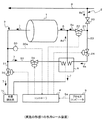
図1は、本発明の実施の形態1による冷却ロール装置を示す構成図である。図において、冷却ロール装置には、冷却ロール1、入側冷媒流路2、出側冷媒流路3、コントローラ4、及びプロセスコンピュータ5が設けられている。冷却ロール1は、例えば連続焼鈍炉等の金属帯の処理設備に含まれるものであり、図示しない金属帯との熱交換を行うことにより金属帯の冷却を行うものである。入側冷媒流路2は冷却ロール1に冷媒6を供給するための配管であり、出側冷媒流路3は冷却ロール1を通過した冷媒6である排出冷媒7が冷却ロール1から排出される配管である。
Hereinafter, embodiments for carrying out the present invention will be described with reference to the drawings.
Embodiment 1 FIG.
FIG. 1 is a configuration diagram showing a cooling roll device according to Embodiment 1 of the present invention. In the figure, the cooling roll device is provided with a cooling roll 1, an inlet-side
入側冷媒流路2には、主制御バルブ20、第1供給流路21、第1供給制御バルブ22、第2供給流路23、及び第2供給制御バルブ24が設けられている。主制御バルブ20は、工業用水道8と第1及び第2供給流路21,23との間に介在されたバルブである。この主制御バルブ20は、開弁されることで、工業用水道8から第1及び第2供給流路21,23への工業用水8aの供給を許容する。すなわち、この実施の形態では、外部冷媒系が工業用水道8により構成され、外部冷媒が工業用水8aにより構成されている。
The inlet side
第1供給流路21は、工業用水道8及び冷却ロール1に接続された配管であり、工業用水道8からの工業用水8aを冷媒6として冷却ロール1に供給するためのものである。第1供給制御バルブ22は、第1供給流路21に設けられたバルブであり、第1供給流路21から冷却ロール1への工業用水8aの供給を制御するためのものである。
The
第2供給流路23は、第1供給流路21と並列に工業用水道8及び冷却ロール1に接続された配管である。すなわち、第2供給流路23には、工業用水道8からの工業用水8aが供給される。この第2供給流路23は、熱交換器9の被加熱流路を構成するものであり、工業用水道8からの工業用水8aと、後述の第2排出流路33を流れる排出冷媒7との間で熱交換を行うものである。つまり、第2供給流路23は、排出冷媒7との熱交換により加温された工業用水8aである加温工業用水8bを冷媒6として冷却ロール1に供給するためのものである。
The second supply channel 23 is a pipe connected to the industrial water 8 and the cooling roll 1 in parallel with the
第2供給制御バルブ24は、第2供給流路23に設けられたバルブであり、第2供給流路23から冷却ロール1への加温工業用水8bの供給を制御するためのものである。なお、第2供給制御バルブ24は、第2供給流路23と第2排出流路33との間で熱交換が行われる箇所よりも上流側(工業用水道8側)に配置されている。これは、熱交換器9を使用しないときに、熱交換器9に工業用水8aが流入することを回避するためである。
The second
出側冷媒流路3には、温度センサ30、第1排出流路31、第1排出制御バルブ32、第2排出流路33、及び第2排出制御バルブ34が設けられている。温度センサ30は、排出冷媒7の温度を検出するセンサである。ここで、排出冷媒7は、冷却ロール1での金属帯との熱交換により冷媒6が加温されたものである。すなわち、排出冷媒7の温度は、冷却ロール1での金属帯の冷却状態を反映している。
The outlet side refrigerant flow path 3 is provided with a
第1排出流路31は、冷却ロール1及び外部排出系10に接続された配管であり、排出冷媒7を外部排出系10(下水道)に排出するためのものである。第1排出制御バルブ32は、第1排出流路31に設けられたバルブであり、第1排出流路31から外部排出系10への排出冷媒7の排出を制御するためのものである。
The
第2排出流路33は、第1排出流路31と並列に冷却ロール1及び外部排出系10に接続された配管である。この第2排出流路33は、熱交換器9の加熱流路を構成するものであり、上述の第2供給流路23との間で熱交換を行うものである。第2排出制御バルブ34は、第2排出流路33に設けられたバルブであり、第2排出流路33から外部排出系10への排出冷媒7の排出を制御するためのものである。なお、第2排出制御バルブ34は、第2供給流路23と第2排出流路33との間で熱交換が行われる箇所よりも上流側(冷却ロール1側)に配置されている。これは、熱交換器9を使用しないときに、熱交換器9に排出冷媒7が流入することを回避するためである。
The second
コントローラ4は、例えばリレー回路又はコンピュータ等により構成されたものであり、第1供給制御バルブ22、第2供給制御バルブ24、温度センサ30、第1排出制御バルブ32、及び第2排出制御バルブ34に接続されている。このコントローラ4は、後に図を用いて説明するように、温度センサ30によって検出された排出冷媒7の検出温度30aに基づいて、各制御バルブ22,24,32,34の動作を制御することで、冷却ロール1での金属帯の冷却能力を管理する。
The
プロセスコンピュータ5は、排出冷媒7の適正温度を設定するための適正温度設定信号5aをコントローラ4に入力するものである。コントローラ4は、適正温度設定信号5aにより設定された排出冷媒7の適正温度と、温度センサ30によって検出された排出冷媒7の検出温度30aとの比較を行い、この比較結果に基づいて各制御バルブ22,24,32,34の開閉制御を行う。
The
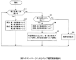
次に、図2は、図1のコントローラ4が行うバルブ開閉制御動作を示すフローチャートである。図において、主制御バルブ20が開弁されて、工業用水道8から第1及び第2供給流路21,23への工業用水8aの供給が許容されると、温度センサ30によって検出された排出冷媒7の検出温度30aが適正温度設定信号5aにより設定された排出冷媒7の適正温度よりも高いか否かが判定される(ステップS1)。このとき、検出温度30aが適正温度より高いと判定されると、第1供給制御バルブ22及び第1排出制御バルブ32が開放されるとともに、第2供給制御バルブ24及び第2排出制御バルブ34が閉成される(ステップS2)。これにより、工業用水道8からのすべての工業用水8aが冷媒6として冷却ロール1に直接供給されて、排出冷媒7の温度が速やかに適正温度まで落とされる。換言すると、金属帯の冷却不足が生じる際に、冷却ロール1での金属帯の冷却能力が速やかに所望の状態とされる。なお、開放とは100%の開度で開かれた状態を示し、閉成とは0%の開度で開かれた状態(100%の閉度で閉じられた状態)を示している。
Next, FIG. 2 is a flowchart showing a valve opening / closing control operation performed by the
これに対して、検出温度30aが適正温度よりも高くないと判定されると、検出温度30aが適正温度よりも低いか否かが判定される(ステップS3)。このとき、検出温度30aが適正温度よりも低いと判定されると、第1供給制御バルブ22が閉成されるとともに第2供給制御バルブ24が開放される(ステップS4)。これと同時に、検出温度30aと適正温度との温度差に応じた開度となるように、第1排出制御バルブ32が閉じられるとともに第2排出制御バルブ34が開かれる(ステップS5)。すなわち、工業用水道8からのすべての工業用水8aが熱交換器9の被加熱側流路に供給され、検出温度30aと適正温度との温度差に応じた流量の排出冷媒7が熱交換器9の加熱流路に供給される。これにより、排出冷媒7の温度が適正温度となるように加温された加温工業用水8bが冷媒6として冷却ロール1に供給される。
On the other hand, if it is determined that the detected
一方で、検出温度30aが適正温度よりも高くなくかつ低くもないと判定された場合には、検出温度30aが適正温度であると判定されて、各制御バルブ22,24,32,34の開閉状態が維持される(ステップS5)。このコントローラ4によるバルブ開閉制御動作は、主制御バルブ20が開弁されているときに繰り返し実施される。
On the other hand, if it is determined that the detected
このような冷却ロール装置では、第1及び第2供給制御バルブ22,24の制御により工業用水8a及び加温工業用水8bが冷媒6として冷却ロール1に供給されるので、状況に応じて冷却ロール1に工業用水8aを直接供給でき、冷却ロール1の温度をより速やかに下げることができる。これにより、冷却ロール1の金属帯の冷却能力をより速やかに所望の状態とすることができ、金属帯の冷却不足が生じる可能性を低減できる。また、出側冷媒流路3を流れる排出冷媒7との間での熱交換により工業用水8aを加温することで加温工業用水8bを生成するので、冷却ロール1の温度制御に外部の熱源を使用せずに済み、操業コストを低減できる。
In such a cooling roll device, the
また、第1及び第2排出制御バルブ32,34による排出冷媒7の排出制御により、工業用水8aと熱交換される排出冷媒7の量が制御されるので、外部排出系10に直接排出される排出冷媒7の量と工業用水8aと熱交換される排出冷媒7の量とを制御することにより加温工業用水8bの温度を制御でき、冷却ロール1の金属帯の冷却能力をより確実に管理できる。
Further, the amount of the discharged
さらに、コントローラ4は、出側冷媒流路3に設けられた温度センサ30によって検出された排出冷媒7の検出温度30aに基づいて、第1供給制御バルブ22、第2供給制御バルブ24、第1排出制御バルブ32、及び第2排出制御バルブ34の動作を制御するので、冷却ロール1での金属帯の冷却能力をより確実に管理できる。すなわち、冷却ロール1での冷却結果である排出冷媒7の温度には、金属帯が過冷却であるか冷却不足であるかがそのまま反映されており、当該排出冷媒7の温度に基づいて各制御バルブ22,24,32,34の開閉状態を制御することで、より確実に冷却ロール1の冷却能力を管理できる。なお、工業用水道8を流れる工業用水8aの温度は短時間で大きく変動しないと考えられるため、温度センサにより工業用水8aの温度を逐次検出しなくても、冷却ロール1の冷却能力管理には大きな誤差は現れないと考えられる。
Further, the
さらにまた、コントローラ4は、設定された排出冷媒7の適正温度と検出温度30aとを比較して、検出温度30aが適正温度よりも高いときは、第1供給制御バルブ22及び第1排出制御バルブ32を開放するとともに、第2供給制御バルブ24及び第2排出制御バルブ34を閉成させ、検出温度30aが適正温度よりも低いときは、第1供給制御バルブ22を閉成するとともに第2供給制御バルブ24を開放し、かつ、検出温度30aと適正温度との温度差に応じた開度となるように、第1排出制御バルブ32を閉じるとともに第2排出制御バルブ34を開くので、より確実に排出冷媒7の温度を適正温度とすることができ、冷却ロール1の金属帯の冷却能力をより確実に所望の状態で維持できる。
Furthermore, the
なお、実施の形態1では、出側冷媒流路3に第1及び第2排出流路31,33が設けられ、排出冷媒7が外部排出系10に直接排出されるか、熱交換器9を介して外部排出系10に排出されるかが選択できるように構成されていたが、第1排出流路31を省略して、出側冷媒流路を流れるすべての排出冷媒が第2供給流路を流れる外部冷媒と熱交換されてもよい。この場合、冷却ロールに流入される冷媒の量を一定に保ちつつ、第1及び第2供給制御バルブの開度の制御により加温冷媒の温度が制御される。
In the first embodiment, the first and
1 冷却ロール
2 入側冷媒流路
3 出側冷媒流路
4 コントローラ
6 冷媒
7 排出冷媒
8 工業用水道(外部冷媒系)
8a 工業用水(外部冷媒)
8b 加温工業用水(加温冷媒)
9 熱交換器
10 外部排出系
21,23 第1及び第2供給流路
22,24 第1及び第2供給制御バルブ
30 温度センサ
30a 検出温度
31,33 第1及び第2排出流路
32,34 第1及び第2排出制御バルブ
DESCRIPTION OF SYMBOLS 1
8a Industrial water (external refrigerant)
8b Warming industrial water (warming refrigerant)
DESCRIPTION OF
Claims (4)
前記冷却ロール(1)に冷媒(6)を供給する入側冷媒流路(2)と、
前記冷却ロール(1)を通過した冷媒(6)である排出冷媒(7)が前記冷却ロール(1)から排出される出側冷媒流路(3)と
を備え、
前記入側冷媒流路(2)は、
前記冷却ロール(1)及び外部冷媒系(8)に接続され、前記冷媒(6)として前記外部冷媒系(8)からの外部冷媒(8a)を前記冷却ロール(1)に供給する第1供給流路(21)と、
前記第1供給流路(21)に設けられ、前記第1供給流路(21)から前記冷却ロール(1)への前記外部冷媒(8a)の供給を制御する第1供給制御バルブ(22)と、
前記第1供給流路(21)と並列に前記冷却ロール(1)及び前記外部冷媒系(8)に接続されるとともに、前記外部冷媒系(8)から前記外部冷媒(8a)が供給され、前記出側冷媒流路(3)を流れる前記排出冷媒(7)との間で熱交換が行われることで加温された前記外部冷媒(8a)である加温冷媒(8b)を前記冷媒(6)として前記冷却ロール(1)に供給する第2供給流路(23)と、
前記第2供給流路(23)に設けられ、前記第2供給流路(23)から前記冷却ロール(1)への前記加温冷媒(8b)の供給を制御する第2供給制御バルブ(24)と
を有することを特徴とする冷却ロール装置。 A cooling roll (1) for cooling the metal strip by exchanging heat with the metal strip;
An inlet-side refrigerant flow path (2) for supplying the refrigerant (6) to the cooling roll (1);
A discharge refrigerant (7) that is a refrigerant (6) that has passed through the cooling roll (1), and a discharge refrigerant path (3) that is discharged from the cooling roll (1);
The inlet-side refrigerant channel (2)
A first supply connected to the cooling roll (1) and the external refrigerant system (8) and supplying the external refrigerant (8a) from the external refrigerant system (8) as the refrigerant (6) to the cooling roll (1). A flow path (21);
A first supply control valve (22) that is provided in the first supply channel (21) and controls the supply of the external refrigerant (8a) from the first supply channel (21) to the cooling roll (1). When,
While being connected to the cooling roll (1) and the external refrigerant system (8) in parallel with the first supply channel (21), the external refrigerant (8a) is supplied from the external refrigerant system (8), Heated refrigerant (8b), which is the external refrigerant (8a) heated by heat exchange with the discharged refrigerant (7) flowing through the outlet-side refrigerant flow path (3), is transferred to the refrigerant ( 6) as a second supply channel (23) for supplying the cooling roll (1);
A second supply control valve (24) provided in the second supply flow path (23) for controlling the supply of the warming refrigerant (8b) from the second supply flow path (23) to the cooling roll (1). ) And a chill roll device.
前記冷却ロール(1)及び外部排出系(10)に接続され、前記排出冷媒(7)を前記外部排出系(10)に排出する第1排出流路(31)と、
前記第1排出流路(31)に設けられ、前記第1排出流路(31)から前記外部排出系(10)への前記排出冷媒(7)の排出を制御する第1排出制御バルブ(32)と、
前記第1排出流路(31)と並列に前記冷却ロール(1)及び前記外部排出系(10)に接続されるとともに、前記冷却ロール(1)から前記排出冷媒(7)が供給され、前記第2供給流路(23)を流れる前記外部冷媒(8a)との間で熱交換された前記排出冷媒(7)を前記外部排出系(10)に排出する第2排出流路(33)と、
前記第2排出流路(33)に設けられ、前記第2排出流路(33)から前記外部排出系(10)への前記排出冷媒(7)の排出を制御する第2排出制御バルブ(34)と
を有することを特徴とする請求項1記載の冷却ロール装置。 The outlet refrigerant flow path (3)
A first discharge passage (31) connected to the cooling roll (1) and an external discharge system (10), and discharging the discharged refrigerant (7) to the external discharge system (10);
A first discharge control valve (32) provided in the first discharge flow path (31) for controlling discharge of the discharged refrigerant (7) from the first discharge flow path (31) to the external discharge system (10). )When,
While being connected to the cooling roll (1) and the external discharge system (10) in parallel with the first discharge flow path (31), the discharged refrigerant (7) is supplied from the cooling roll (1), A second discharge channel (33) for discharging the discharged refrigerant (7) heat-exchanged with the external refrigerant (8a) flowing through the second supply channel (23) to the external discharge system (10); ,
A second discharge control valve (34) provided in the second discharge flow path (33) for controlling discharge of the discharged refrigerant (7) from the second discharge flow path (33) to the external discharge system (10). The cooling roll device according to claim 1, further comprising:
前記第1供給制御バルブ(22)、前記第2供給制御バルブ(24)、前記第1排出制御バルブ(32)、前記第2排出制御バルブ(34)、及び前記温度センサ(30)に接続されたコントローラ(4)と
をさらに備え、
前記コントローラ(4)は、前記温度センサ(30)によって検出された前記排出冷媒(7)の検出温度(30a)に基づいて、前記第1供給制御バルブ(22)、前記第2供給制御バルブ(24)、前記第1排出制御バルブ(32)、及び前記第2排出制御バルブ(34)の動作を制御することを特徴とする請求項2記載の冷却ロール装置。 A temperature sensor (30) provided in the outlet-side refrigerant flow path (3) for detecting the temperature of the discharged refrigerant (7);
Connected to the first supply control valve (22), the second supply control valve (24), the first discharge control valve (32), the second discharge control valve (34), and the temperature sensor (30). And a controller (4)
The controller (4) includes the first supply control valve (22) and the second supply control valve (based on the detected temperature (30a) of the exhaust refrigerant (7) detected by the temperature sensor (30). 24. The chill roll device according to claim 2, wherein operations of the first discharge control valve (32) and the second discharge control valve (34) are controlled.
設定された前記排出冷媒(7)の適正温度と前記検出温度(30a)とを比較して、
前記検出温度(30a)が前記適正温度よりも高いときは、前記第1供給制御バルブ(22)及び前記第1排出制御バルブ(32)を開放するとともに、前記第2供給制御バルブ(24)及び前記第2排出制御バルブ(34)を閉成させ、
前記検出温度(30a)が前記適正温度よりも低いときは、前記第1供給制御バルブ(22)を閉成するとともに前記第2供給制御バルブ(24)を開放し、かつ、前記検出温度(30a)と前記適正温度との温度差に応じた開度となるように、前記第1排出制御バルブ(32)を閉じるとともに前記第2排出制御バルブ(34)を開く
ことを特徴とする請求項3記載の冷却ロール装置。 The controller (4)
Comparing the set appropriate temperature of the discharged refrigerant (7) and the detected temperature (30a),
When the detected temperature (30a) is higher than the appropriate temperature, the first supply control valve (22) and the first discharge control valve (32) are opened, and the second supply control valve (24) and Closing the second discharge control valve (34);
When the detected temperature (30a) is lower than the appropriate temperature, the first supply control valve (22) is closed, the second supply control valve (24) is opened, and the detected temperature (30a) The first discharge control valve (32) is closed and the second discharge control valve (34) is opened so that the opening degree corresponds to the temperature difference between the temperature and the appropriate temperature. The cooling roll apparatus as described.
Priority Applications (1)
| Application Number | Priority Date | Filing Date | Title |
|---|---|---|---|
| JP2011030887A JP5616814B2 (en) | 2011-02-16 | 2011-02-16 | Cooling roll device |
Applications Claiming Priority (1)
| Application Number | Priority Date | Filing Date | Title |
|---|---|---|---|
| JP2011030887A JP5616814B2 (en) | 2011-02-16 | 2011-02-16 | Cooling roll device |
Publications (2)
| Publication Number | Publication Date |
|---|---|
| JP2012167352A true JP2012167352A (en) | 2012-09-06 |
| JP5616814B2 JP5616814B2 (en) | 2014-10-29 |
Family
ID=46971766
Family Applications (1)
| Application Number | Title | Priority Date | Filing Date |
|---|---|---|---|
| JP2011030887A Expired - Fee Related JP5616814B2 (en) | 2011-02-16 | 2011-02-16 | Cooling roll device |
Country Status (1)
| Country | Link |
|---|---|
| JP (1) | JP5616814B2 (en) |
Citations (3)
| Publication number | Priority date | Publication date | Assignee | Title |
|---|---|---|---|---|
| JPS54118315A (en) * | 1978-03-08 | 1979-09-13 | Nippon Kokan Kk <Nkk> | Metal belt cooling |
| JPS5920429A (en) * | 1982-07-26 | 1984-02-02 | Nippon Kokan Kk <Nkk> | Steel strip cooling method in continuous annealing furnace |
| JPS6046327A (en) * | 1983-08-23 | 1985-03-13 | Nippon Kokan Kk <Nkk> | Method of cooling metal strips using cooling rolls |
-
2011
- 2011-02-16 JP JP2011030887A patent/JP5616814B2/en not_active Expired - Fee Related
Patent Citations (3)
| Publication number | Priority date | Publication date | Assignee | Title |
|---|---|---|---|---|
| JPS54118315A (en) * | 1978-03-08 | 1979-09-13 | Nippon Kokan Kk <Nkk> | Metal belt cooling |
| JPS5920429A (en) * | 1982-07-26 | 1984-02-02 | Nippon Kokan Kk <Nkk> | Steel strip cooling method in continuous annealing furnace |
| JPS6046327A (en) * | 1983-08-23 | 1985-03-13 | Nippon Kokan Kk <Nkk> | Method of cooling metal strips using cooling rolls |
Also Published As
| Publication number | Publication date |
|---|---|
| JP5616814B2 (en) | 2014-10-29 |
Similar Documents
| Publication | Publication Date | Title |
|---|---|---|
| JP5306708B2 (en) | Refrigerant cooling device | |
| JP2011173543A (en) | Battery cooling/heating device | |
| TWI887444B (en) | Chiller | |
| CN111578389B (en) | Outer machine heat exchanger, high-temperature-prevention control device and control method and air conditioner | |
| CN101551151B (en) | Flow control system | |
| JP5486425B2 (en) | Water heat source heat pump unit piping system | |
| JP5616814B2 (en) | Cooling roll device | |
| JP6250589B2 (en) | Air conditioning system | |
| JP5677099B2 (en) | A method for controlling a heat source system including a plurality of types of heat source devices. | |
| JP7388113B2 (en) | Method for estimating the bypass ratio of a heat exchange system equipped with a heat medium bypass flow path | |
| JP2008224155A (en) | Ice storage type heat source apparatus and control method thereof | |
| JP2003130428A (en) | Combined cooling and heating water system | |
| JP3839915B2 (en) | Refrigerant cooling device | |
| JP2009243718A (en) | Heat medium transporting system | |
| JP4871800B2 (en) | Chiller device | |
| JP4006324B2 (en) | Fluid cooling device | |
| JP2008039230A (en) | Heat medium piping system | |
| JP6379985B2 (en) | Heat recovery system | |
| JP6323294B2 (en) | Heat recovery system | |
| JP5268857B2 (en) | Temperature control device | |
| JP6350815B2 (en) | Heat recovery system | |
| JP2018204838A (en) | Refrigeration system and control device of refrigeration system | |
| JP2009109059A (en) | Air conditioner | |
| JP2013232603A (en) | Temperature control device | |
| KR20100136763A (en) | Machine tool drive unit with temperature control part of working oil |
Legal Events
| Date | Code | Title | Description |
|---|---|---|---|
| A621 | Written request for application examination |
Free format text: JAPANESE INTERMEDIATE CODE: A621 Effective date: 20140110 |
|
| A977 | Report on retrieval |
Free format text: JAPANESE INTERMEDIATE CODE: A971007 Effective date: 20140812 |
|
| TRDD | Decision of grant or rejection written | ||
| A01 | Written decision to grant a patent or to grant a registration (utility model) |
Free format text: JAPANESE INTERMEDIATE CODE: A01 Effective date: 20140819 |
|
| A61 | First payment of annual fees (during grant procedure) |
Free format text: JAPANESE INTERMEDIATE CODE: A61 Effective date: 20140912 |
|
| R150 | Certificate of patent or registration of utility model |
Ref document number: 5616814 Country of ref document: JP Free format text: JAPANESE INTERMEDIATE CODE: R150 |
|
| R250 | Receipt of annual fees |
Free format text: JAPANESE INTERMEDIATE CODE: R250 |
|
| R250 | Receipt of annual fees |
Free format text: JAPANESE INTERMEDIATE CODE: R250 |
|
| R250 | Receipt of annual fees |
Free format text: JAPANESE INTERMEDIATE CODE: R250 |
|
| R250 | Receipt of annual fees |
Free format text: JAPANESE INTERMEDIATE CODE: R250 |
|
| S111 | Request for change of ownership or part of ownership |
Free format text: JAPANESE INTERMEDIATE CODE: R313115 |
|
| R250 | Receipt of annual fees |
Free format text: JAPANESE INTERMEDIATE CODE: R250 |
|
| R350 | Written notification of registration of transfer |
Free format text: JAPANESE INTERMEDIATE CODE: R350 |
|
| R250 | Receipt of annual fees |
Free format text: JAPANESE INTERMEDIATE CODE: R250 |
|
| LAPS | Cancellation because of no payment of annual fees |