JP2012166751A - Steering device - Google Patents
Steering device Download PDFInfo
- Publication number
- JP2012166751A JP2012166751A JP2011030933A JP2011030933A JP2012166751A JP 2012166751 A JP2012166751 A JP 2012166751A JP 2011030933 A JP2011030933 A JP 2011030933A JP 2011030933 A JP2011030933 A JP 2011030933A JP 2012166751 A JP2012166751 A JP 2012166751A
- Authority
- JP
- Japan
- Prior art keywords
- steering
- shaft
- wire
- lower shaft
- column
- Prior art date
- Legal status (The legal status is an assumption and is not a legal conclusion. Google has not performed a legal analysis and makes no representation as to the accuracy of the status listed.)
- Granted
Links
Images


Landscapes
- Steering Controls (AREA)
Abstract
【課題】ステアリングホイールを車両後方側へ移動させても、移動部材が固定部材に対して抜けてしまうことを防止することができ、しかも、そのステアリングコラムの車両本体に対する組み付け性を向上させること。
【解決手段】アッパシャフト11の一端とロアシャフト12の一端とが、ステアリングコラム6内に配設されたワイヤ81によって連結されている。このため、アッパブラケット26が取付ステー24に対して離脱し、且つインナチューブ14とアウタチューブ13との摩擦係合が解除された状態で、ステアリング位置を車両後方側へ移動させるとき、ワイヤ81によりアウタチューブ13及びアッパシャフト11が、インナチューブ14及びロアシャフト12に対して抜けてしまうことを防止することができる。
【選択図】図1An object of the present invention is to prevent a moving member from being detached from a fixed member even when a steering wheel is moved to the rear side of the vehicle, and to improve the assembly of the steering column to the vehicle body.
One end of an upper shaft 11 and one end of a lower shaft 12 are connected by a wire 81 provided in a steering column 6. Therefore, when the upper bracket 26 is detached from the mounting stay 24 and the frictional engagement between the inner tube 14 and the outer tube 13 is released, the steering position is moved to the vehicle rear side by the wire 81. It is possible to prevent the outer tube 13 and the upper shaft 11 from coming out of the inner tube 14 and the lower shaft 12.
[Selection] Figure 1
Description
本発明は、ステアリング装置に関する。 The present invention relates to a steering device.
車両のステアリング装置としては、ステアリングホイールが連結されるステアリングシャフトを回転可能に支持するステアリングコラムと、締結装置により車両本体に固定されステアリングコラムを支持する固定ブラケットとを備え、固定ブラケットが、所定荷重以上の荷重が作用することにより車両本体に対して離脱するように構成されたものがある。 The vehicle steering device includes a steering column that rotatably supports a steering shaft to which a steering wheel is coupled, and a fixed bracket that is fixed to the vehicle body by a fastening device and supports the steering column. Some are configured to be detached from the vehicle body when the above load is applied.
このようなステアリング装置において、ステアリングシャフトは、アッパシャフトと、アッパシャフトに収容されるロアシャフトとを有し、アッパシャフト及びロアシャフトはスプライン嵌合により連結されている。また、ステアリングコラムは、アッパシャフトを収容支持するアウタチューブと、ロアシャフトを収容するインナチューブとを有し、アウタチューブ及びインナチューブは互いに嵌合されることにより連結されている。そして、ステアリングシャフト及びステアリングコラムにおいては、ロアシャフト及びインナチューブが車両本体に固定される固定部材を構成し、アッパシャフト及びアウタチューブが固定部材に対して移動する移動部材を構成している。また、ステアリング装置は、固定部材に対して移動部材が相対移動してステアリングホイールにおける車両前後方向のステアリング位置を調整可能とするテレスコピック機構と、ステアリングホイールのステアリング位置を保持するロック機構とを有している。 In such a steering apparatus, the steering shaft has an upper shaft and a lower shaft accommodated in the upper shaft, and the upper shaft and the lower shaft are connected by spline fitting. The steering column has an outer tube that accommodates and supports the upper shaft, and an inner tube that accommodates the lower shaft, and the outer tube and the inner tube are connected to each other by being fitted to each other. In the steering shaft and the steering column, the lower shaft and the inner tube constitute a fixing member that is fixed to the vehicle body, and the upper shaft and the outer tube constitute a moving member that moves relative to the fixing member. In addition, the steering device includes a telescopic mechanism that allows the moving position of the moving member relative to the fixed member to adjust the steering position of the steering wheel in the vehicle front-rear direction, and a lock mechanism that holds the steering position of the steering wheel. ing.
そして、ステアリングコラムは固定ブラケットに保持され、この固定ブラケットが車両本体に取り付けられることで、ステアリングコラムは車両本体に取り付けられている。ロック機構がロックされている状態では、ロック機構によりアウタチューブのインナチューブに対する相対移動が規制され、ステアリングホイールのステアリング位置が保持されている。一方、ロック機構のロックを解除すると、アウタチューブのインナチューブに対する相対移動が許容され、アウタチューブのインナチューブに対する相対移動により、アッパシャフトがロアシャフトに対して相対移動して、テレスコピック機構によりステアリングホイールのステアリング位置を調整可能になっている(例えば特許文献1参照)。 The steering column is held by a fixed bracket, and the steering column is attached to the vehicle body by attaching the fixed bracket to the vehicle body. In a state where the lock mechanism is locked, relative movement of the outer tube with respect to the inner tube is restricted by the lock mechanism, and the steering position of the steering wheel is maintained. On the other hand, when the lock mechanism is unlocked, the outer tube is allowed to move relative to the inner tube, and the outer tube moves relative to the inner tube, so that the upper shaft moves relative to the lower shaft, and the telescopic mechanism moves the steering wheel. The steering position can be adjusted (see, for example, Patent Document 1).
ところで、例えば車両が前面衝突し、慣性の作用により運転者がステアリングホイールに衝突(二次衝突)した場合には、その衝撃緩和等を目的として、固定ブラケットが車両本体から離脱し、ステアリングコラムが収縮させられる。固定ブラケットが車両本体から離脱した後は、ステアリングコラムが車両本体に対して支持されなくなる。ステアリングコラムが車両本体に対して支持されていない状態において、ロック機構のロックを解除し、ステアリングホイールを車両後方側へ移動させようとすると、インナチューブ及びロアシャフトに対してアウタチューブ及びアッパシャフトが抜けてしまう虞がある。また、ステアリングコラムにおける車両本体への組み付け作業中にも同様の状態となることがあり、組み付け性を悪化させている。 By the way, for example, when the vehicle collides with the front and the driver collides with the steering wheel due to inertia (secondary collision), the fixed bracket is detached from the vehicle body for the purpose of mitigating the impact, and the steering column is Shrinked. After the fixing bracket is detached from the vehicle body, the steering column is not supported on the vehicle body. In a state where the steering column is not supported by the vehicle body, when the lock mechanism is unlocked and the steering wheel is moved to the rear side of the vehicle, the outer tube and the upper shaft are moved against the inner tube and the lower shaft. There is a risk of falling out. Further, the same state may be caused during the assembly work to the vehicle body in the steering column, which deteriorates the assemblability.
本発明の目的は、ステアリングホイールを車両後方側へ移動させても、移動部材が固定部材に対して抜けてしまうことを防止することができ、しかも、そのステアリングコラムの車両本体に対する組み付け性を向上させることができるステアリング装置を提供することにある。 An object of the present invention is to prevent the moving member from coming off from the fixed member even when the steering wheel is moved to the rear side of the vehicle, and to improve the assembly of the steering column to the vehicle body. An object of the present invention is to provide a steering device that can be made to operate.
上記目的を達成するため、請求項1に記載の発明は、ステアリングホイールが連結されるステアリングシャフトと、前記ステアリングシャフトを回転可能に支持するステアリングコラムとを有するとともに、前記ステアリングシャフト及び前記ステアリングコラムは、車両本体に固定される固定部材と、前記固定部材に対して車両前後方向に相対移動可能な移動部材とを備え、さらに、前記固定部材に対して前記移動部材が相対移動して前記ステアリングホイールにおける車両前後方向のステアリング位置を調整可能なテレスコピック機構と、前記ステアリングホイールにおける車両前後方向のステアリング位置を保持するロック機構と、を有するステアリング装置において、前記固定部材と前記移動部材とが前記ステアリングコラム内に配設される連結部材によって連結されていることを要旨とする。
In order to achieve the above object, the invention according to
上記構成によれば、テレスコピック機構によりステアリング位置を車両後方側へ調整しようとしたとき、連結部材により移動部材が固定部材に対して抜けてしまうことを防止することができる。また、ステアリングコラムにおける車両本体への組み付け作業中においても、連結部材により移動部材が固定部材に対して抜けてしまうことが防止され、車両本体に対するステアリングコラムの組み付け性を向上させることができる。さらに、この連結部材はステアリングコラム内に配設されているため、車両本体に対してステアリングコラムを組み付ける際に、連結部材が車両本体等に干渉して邪魔になるといったことがない。 According to the said structure, when it is going to adjust a steering position to a vehicle rear side with a telescopic mechanism, it can prevent that a moving member detaches | leaves with respect to a fixed member by a connection member. Further, even during the assembly work of the steering column to the vehicle body, the connecting member prevents the moving member from coming off from the fixed member, and the ease of assembly of the steering column to the vehicle body can be improved. Further, since the connecting member is disposed in the steering column, the connecting member does not interfere with the vehicle body and the like when the steering column is assembled to the vehicle body.
請求項2に記載の発明は、請求項1に記載のステアリング装置において、前記固定部材は、前記ステアリングシャフトのロアシャフト、及び前記ステアリングコラムのインナチューブであり、前記移動部材は、前記ステアリングシャフトのアッパシャフト、及び前記アッパシャフトと一体的に相対移動可能な前記ステアリングコラムのアウタチューブであり、前記連結部材は、線材と、前記線材の一端に設けられるとともに前記ロアシャフトに連結される第1連結部と、前記線材の他端に設けられるとともに前記アッパシャフトに連結される第2連結部とからなることを要旨とする。 According to a second aspect of the present invention, in the steering apparatus according to the first aspect, the fixing member is a lower shaft of the steering shaft and an inner tube of the steering column, and the moving member is a member of the steering shaft. An upper shaft and an outer tube of the steering column that is integrally movable relative to the upper shaft, wherein the connecting member is provided at one end of the wire and connected to the lower shaft. And a second connecting portion provided at the other end of the wire and connected to the upper shaft.
上記構成によれば、第1連結部をロアシャフトに連結することで、連結部材とロアシャフトとを連結することができるとともに、第2連結部をアッパシャフトに連結することで、連結部材とアッパシャフトとを連結することができる。 According to the above configuration, the connecting member and the lower shaft can be connected by connecting the first connecting portion to the lower shaft, and the connecting member and the upper can be connected by connecting the second connecting portion to the upper shaft. The shaft can be connected.
請求項3に記載の発明は、請求項1又は請求項2に記載のステアリング装置において、前記連結部材は、前記移動部材が前記固定部材から抜けない長さであり、且つ前記テレスコピック機構による前記ステアリングホイールにおける車両前後方向のステアリング位置を調整可能な長さに設定されていることを要旨とする。 According to a third aspect of the present invention, in the steering apparatus according to the first or second aspect, the connecting member has a length that prevents the moving member from coming off the fixed member, and the steering by the telescopic mechanism. The gist is that the steering position of the wheel in the longitudinal direction of the vehicle is set to an adjustable length.
上記構成によれば、ステアリングホイールを車両後方側へ移動させてテレスコピック機構によりステアリング位置を調整する際に、移動部材が固定部材から抜けてしまうことがなく、連結部材がこの調整の妨げになってしまうことを回避することができる。 According to the above configuration, when the steering wheel is moved to the vehicle rear side and the steering position is adjusted by the telescopic mechanism, the moving member does not come out of the fixed member, and the connecting member hinders this adjustment. Can be avoided.
本発明によれば、ステアリングホイールを車両後方側へ移動させても、移動部材が固定部材に対して抜けてしまうことを防止することができ、しかも、そのステアリングコラムの車両本体に対する組み付け性を向上させることができる。 According to the present invention, even if the steering wheel is moved to the rear side of the vehicle, it is possible to prevent the moving member from coming off from the fixed member, and to improve the assembly of the steering column to the vehicle body. Can be made.
以下、本発明を具体化した一実施形態を図面に従って説明する。
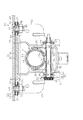
図1に示すように、ステアリング装置1は、車両後方側の端部(図1の右側端部)にステアリングホイール2が固定されるステアリングシャフト3を備えている。ステアリングシャフト3は、軸受5に軸支されることによりステアリングコラム6内において回転可能に収容されている。ステアリングシャフト3における車両前方側の端部(図1の左側端部)は自在継手を介してインターミディエイトシャフト(図示せず)に連結されている。よって、ステアリング操作に伴う回転及び操舵トルクが、ラックアンドピニオン機構等の図示しない転舵輪の舵角を変更する転舵機構へと伝達されるようになっている。なお、ステアリングシャフト3は、車両前方側端部が鉛直方向下側に位置するように傾斜した状態で車両に搭載されている。
DESCRIPTION OF EXEMPLARY EMBODIMENTS Hereinafter, an embodiment of the invention will be described with reference to the drawings.
As shown in FIG. 1, the
また、ステアリング装置1は、鉛直方向におけるステアリングホイール2の位置(ステアリング位置)の調整を可能とする所謂チルト調整機能、及びステアリングシャフト3の軸線方向におけるステアリング位置の調整を可能とする所謂テレスコ調整機能を有している。
The
ステアリングシャフト3は、ステアリングホイール2が固定される中空状のアッパシャフト11と、アッパシャフト11に収容されるロアシャフト12とを備えている。アッパシャフト11の内周にはスプライン嵌合部11aが形成されるとともに、ロアシャフト12の外周にはスプライン嵌合部12aが形成されている。そして、アッパシャフト11とロアシャフト12とは、各スプライン嵌合部11a,12aがスプライン嵌合することにより軸線方向へ相対摺動可能、且つ一体回転可能に構成されている。
The steering shaft 3 includes a hollow
また、ステアリングコラム6は、軸受5を介してアッパシャフト11を収容支持するアウタチューブ13と、ロアシャフト12を収容するインナチューブ14とを備えている。アウタチューブ13は、その内周にインナチューブ14が挿入されることにより、インナチューブに対して軸線方向に相対摺動可能に設けられている。
Further, the
インナチューブ14の他端には、操舵系にステアリング操作を補助するためのアシスト力を付与するEPSアクチュエータ(図示せず)の出力軸16が収容されるハウジング17が設けられている。出力軸16は、その一端がロアシャフト12の他端に形成される凹部12cに圧入されることで、ロアシャフト12の他端に連結されるとともに、ハウジング内に軸受19〜21を介して回転可能に支持されている。出力軸16は、アッパシャフト11及びロアシャフト12と共にステアリングシャフト3を構成している。出力軸16にはウォームホイール22が固定されており、ウォームホイール22及び図示しないウォームギアにより構成される減速機構を介して、図示しないモータの回転を出力軸16に伝達することにより、操舵系に対してアシスト力を付与することが可能な構成になっている。
The other end of the
ステアリングコラム6は、車両本体の一部を構成する取付ステー24の車両前方側に固定されたロアブラケット25によって、ハウジング17に設けられたチルト中心軸Oを中心として傾動可能に支持されている。また、ステアリングコラム6は、取付ステー24の車両後方側に固定されたアッパブラケット26によって、アウタチューブ13がチルト中心軸Oを中心として傾動可能、且つ軸線方向へ移動可能に支持されている。
The
図2及び図3に示すように、アッパブラケット26は、取付ステー24に固定される車体側ブラケット31と、ステアリングコラム6(アウタチューブ13)が固定されるコラム側ブラケット32と、これら車体側ブラケット31とコラム側ブラケット32とを連結する支軸33とを備えている。
2 and 3, the
車体側ブラケット31は、ステアリングシャフト3の軸線方向視で略コ字状に形成されるクランプ部35、及びクランプ部35の上端に固定される平板状のプレート部36とから構成されている。そして、クランプ部35に設けられた一対の側板37には、ステアリングコラム6の傾動方向に沿った略円弧状のチルト長孔38がそれぞれ形成されている。また、コラム側ブラケット32は、ステアリングシャフト3の軸線方向視で略コ字状に形成されるとともに、コラム側ブラケット32に設けられた一対の側板41には、軸線方向に沿って延びるテレスコ長孔42が形成されている。さらに、車体側ブラケット31には、その剛性を確保すべく、ステアリングシャフト3の軸線方向と直交する補強部43が側板41の左右方向(図2の左右方向)両側にそれぞれ形成されている。
The vehicle
支軸33の基端側(図2の左側)には径方向外側へ延出される円板状の頭部45が形成されている。そして、支軸33は、コラム側ブラケット32が車体側ブラケット31の内側に配置された状態で、両ブラケット31,32にそれぞれ形成されたチルト長孔38及びテレスコ長孔42に挿通されることにより、車体側ブラケット31とコラム側ブラケット32とを連結している。支軸33の先端側(図2の右側)にはナット46が螺着されることにより、支軸33が両ブラケット31,32に対してその軸方向へ移動不能に固定されている。これにより、コラム側ブラケット32は、チルト長孔38の形成された範囲内で車体側ブラケット31に対してチルト中心軸Oを中心として傾動可能になっている。また、コラム側ブラケット32は、テレスコ長孔42の形成された範囲内で軸線方向に沿って移動可能になっている。つまり、アッパブラケット26は、上記範囲内でステアリングコラム6を傾動可能、且つ軸方向へ移動可能に支持している。
A disc-shaped head 45 extending outward in the radial direction is formed on the base end side (left side in FIG. 2) of the
ステアリング装置1には、鉛直方向及び軸線方向におけるステアリング位置を保持するためのロック機構51が設けられている。ロック機構51は、支軸33を中心として支軸33と一体で回動可能に設けられた操作レバー52と、支軸33の頭部45とクランプ部35の側板37との間に設けられ、操作レバー52(支軸33)の回動位置に応じて側板37を支軸33の軸方向先端側(図3の右側)に押圧するカム機構53とを備えている。カム機構53は、支軸33と一体回転する第1カム部材54、及び第1カム部材54と相対回転可能な第2カム部材55からなり、その相対回転位置に応じてこれら第1カム部材54と第2カム部材55とが接離する構成になっている。
The
また、ロック機構51は、操作レバー52の回動位置に応じてインナチューブ14を、ステアリングシャフト3の軸線方向及び車両上下方向における上側に押圧する略筒状の押圧部材56を備えている。支軸33の外周にはスプライン嵌合部33aが形成されるとともに、押圧部材56の内周にはスプライン嵌合部56aが形成されており、押圧部材56はスプライン嵌合することにより、支軸33と一体回転するように構成されている。押圧部材56は、支軸33の中心に対して偏心した位置に配置される断面円弧状のカム部57を有しており、カム部57はアウタチューブ13の下部に形成された開口13aを介してインナチューブ14に当接している。そして、支軸33の回動位置に応じて、カム部57がインナチューブ14を押圧する構成になっている。
The lock mechanism 51 includes a substantially cylindrical pressing
操作レバー52を周方向一方側に回動させることで、カム機構53によって両ブラケット31,32の各側板37,41同士が摩擦係合するとともに、押圧部材56によってインナチューブ14の外周面とアウタチューブ13の内周面とが摩擦係合する。これにより、コラム側ブラケット32が車体側ブラケット31に対して相対移動できなくなり、ステアリング位置を変更不能なロック状態になる。一方、操作レバー52を周方向他方側に回動させることで、カム機構53による押圧力が無くなって両ブラケット31,32の各側板37,41同士の摩擦係合が解除されるとともに、押圧部材56による押圧力が無くなり、インナチューブ14とアウタチューブ13との摩擦係合が解除される。これにより、コラム側ブラケット32が車体側ブラケット31に対して相対移動可能になり、ステアリング位置を変更可能なアンロック状態になる。
By rotating the
このように構成されたステアリング装置1では、ロック機構51をアンロック状態とし、車体側ブラケット31に対してコラム側ブラケット32及びステアリングコラム6を傾動させることにより、チルト長孔38の範囲内で上下方向におけるステアリング位置を調整可能な構成になっている。また、インナチューブ14及びロアシャフト12に対してアウタチューブ13及びアッパシャフト11を相対移動させるとともに、車体側ブラケット31に対してコラム側ブラケット32を軸方向に相対移動させることにより、テレスコ長孔42の範囲内で軸線方向におけるステアリング位置を調整可能な構成になっている。よって、本実施形態では、ロアシャフト12及びインナチューブ14は、車両本体に固定される固定部材の一部を構成するとともに、アッパシャフト11及びアウタチューブ13は、固定部材に対して相対移動可能な移動部材の一部を構成している。また、本実施形態では、支軸33、テレスコ長孔42、コラム側ブラケット32及びアウタチューブ13によりテレスコピック機構が構成される。
In the
ここで、アッパブラケット26は、例えば二次衝突時にステアリングコラム6が車両本体の一部を構成する取付ステー24から離脱すべく、アッパブラケット26に対して所定荷重以上の車両前方への荷重が作用したときに、取付ステー24から離脱する所謂ブレークアウェイブラケットとして構成されている。
Here, in the
車体側ブラケット31のプレート部36は、クランプ部35の車両幅方向両側に延出する延出部61を有しており、これら各延出部61には、ステアリングシャフト3の軸線方向に沿って延びるとともに車両後方側に開口した締結孔62がそれぞれ形成されている。そして、アッパブラケット26(車体側ブラケット31)は、各締結孔62にカプセル機構63を介して取付ステー24から突出するボルト64が挿通されるとともに、ボルト64にナット65が締結されることで、取付ステー24に固定されている。
The
カプセル機構63は、アッパブラケット26(プレート部36)と取付ステー24との間に介在される平板状のカプセル73を備えている。また、カプセル機構63は、ボルト64が挿通される円筒状のカラー75と、カラー75に外嵌される円環状の皿ばね76と、皿ばね76を収容する円環状のハウジング77とを備えている。そして、カプセル機構63は、ボルト64の先端側にナット65が螺着されることで、皿ばね76が弾性変形した状態で取付ステー24に固定されている。この皿ばね76の付勢力により、アッパブラケット26が離脱する際に、カプセル73とプレート部36及び取付ステー24との間に付勢力に応じた摩擦力が作用するようになっている。そして、アッパブラケット26は、アッパブラケット26に対して所定荷重以上の車両前方への荷重が作用すると、カプセル機構63を車両本体に残した状態で、ステアリングシャフト3の軸線方向における車両前方側に離脱するようになっている。
The
図1に示すように、本実施形態のステアリング装置1において、アッパシャフト11の一端とロアシャフト12の一端とが、ステアリングコラム6内に配設された連結部材としてのワイヤ81によって連結されている。
As shown in FIG. 1, in the
図1において拡大して示すように、ロアシャフト12の一端側外周面には溝状の係止凹部12bがロアシャフト12の全周に亘って形成されている。係止凹部12bは、ロアシャフト12の径方向に延びるとともにロアシャフト12の一端側に位置する一方の側面121bを有する。係止凹部12bは、ロアシャフト12の径方向に延びるとともにロアシャフト12の他端側に位置する他方の側面122bを有する。係止凹部12bはロアシャフト12の周方向に延びるとともに一方の側面121bと他方の側面122bにおけるロアシャフト12の中心軸線側の縁部同士を繋ぐ底面123bを有する。
As shown in an enlarged manner in FIG. 1, a groove-shaped
図4に示すように、ワイヤ81は、金属製の線材82と、線材82の一端に設けられる第1連結部83と、線材82の他端に設けられる第2連結部84とから構成されている。線材82の長さは、アウタチューブ13及びアッパシャフト11が、インナチューブ14及びロアシャフト12に対して抜けない長さであり、且つテレスコ長孔42の範囲内で軸線方向におけるステアリング位置を調整可能な長さに設定されている。具体的には、ステアリング位置をテレスコ長孔42の範囲内で軸線方向における最も車両後方側に調整したときにも、線材82がステアリングコラム6内において撓んだ状態になるように、線材82の長さが設定されている。すなわち、線材82の長さは、ステアリング位置をテレスコ長孔42の範囲内で軸線方向における最も車両後方側に調整した状態でのロアシャフト12の係止凹部12bからアッパシャフト11の一端開口部11bまでの間の距離よりも長くなっている。
As shown in FIG. 4, the
また、線材82の長さは、例えば二次衝突した場合に、その衝撃緩和等を目的として、アッパブラケット26が取付ステー24から離脱し、ステアリングコラム6が収縮するときに、ステアリングコラム6が収縮不能にならない程度の長さに設定されている。具体的には、ステアリングホイール2が、テレスコ長孔42の範囲内で軸線方向に車両前方側に移動するときに、線材82が撓み過ぎて抵抗になってしまうことが無いように、極度に長くない程度に線材82の長さが設定されている。
Further, the length of the
第1連結部83は、線材82の一端が接続される略矩形ブロック状の接続部83aを有する。線材82の一端は、接続部83aに対して抜け止めされた状態で連結されている。第1連結部83は、接続部83aの他端に連続するとともに接続部83aの長手方向に対して直交する方向へ延びる係止部83bを有する。係止部83bは、不完全環状をなすとともに係止部83bの一端831bと他端832bとの間にはスリット833bが形成されている。係止部83bの厚みは、係止凹部12bの一方の側面121bと他方の側面122bとの間の長さよりも僅かに薄くなっている。係止部83bは、係止部83bの径方向において、スリット833bと対向する部位を基点に、一端831bと他端832bとが接離する方向へ弾性変形し易くなっている。
The
第2連結部84は円柱状をなすとともに、アッパシャフト11の一端開口部11bに圧入される圧入部84aと、圧入部84aよりも大径をなす当接部84bとからなる。圧入部84aの直径は、アッパシャフト11の一端開口部11bの内径よりも僅かに大きくなっている。当接部84bにおける圧入部84a側の端面841bは、アッパシャフト11の一端面11cに当接可能になっている。圧入部84aは、アッパシャフト11の一端開口部11bに、当接部84bの端面841bがアッパシャフト11の一端面11cに当接するまで強制的に押し込むことで圧入される。線材82の他端は、圧入部84aに対して抜け止めされた状態で連結されている。
The second connecting
次に、上記構成のワイヤ81を用いてアッパシャフト11の一端とロアシャフト12の一端とを連結させる手順について説明する。なお、線材82の一端は接続部83aに連結されているとともに、線材82の他端は圧入部84aに連結されていないものとする。
Next, a procedure for connecting one end of the
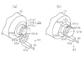
まず、アウタチューブ13及びアッパシャフト11を、インナチューブ14及びロアシャフト12に対してスプライン嵌合する前の状態において、図5(a)に示すように、第1連結部83の係止部83bを、スリット833b側からロアシャフト12の係止凹部12bに向けて挿入する。そして、係止部83bの一端831b及び他端832bが係止凹部12bの底面123bに当接したら、係止部83bを係止凹部12bの底面123bに対して強制的に押し込む。すると、係止部83bが、係止部83bの径方向において、スリット833bと対向する部位を基点に、一端831bと他端832bとが離間する方向へ弾性変形する。これにより、図5(b)に示すように、係止部83bの一端831bと他端832bとが、係止凹部12bの底面123bを乗り越えて、係止部83bが係止凹部12bに係止される。
First, in a state before the
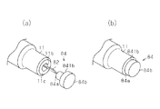
続いて、アウタチューブ13及びアッパシャフト11を、インナチューブ14及びロアシャフト12に対してスプライン嵌合させる。このとき、線材82の他端がアッパシャフト11の一端開口部11bを通過してステアリングコラム6の外側に位置するようにする。そして、図6(a)に示すように、圧入部84aに線材82の他端を連結し、図6(b)に示すように、圧入部84aをアッパシャフト11の一端開口部11bに圧入する。これにより、アッパシャフト11の一端とロアシャフト12の一端とがワイヤ81により連結される。
Subsequently, the
次に、本実施形態のステアリング装置1の作用について説明する。
アッパブラケット26に対して所定荷重以上の車両前方への荷重が作用すると、アッパブラケット26が取付ステー24から離脱する。ここで、衝撃等により、操作レバー52が周方向他方側に回動してしまい、インナチューブ14とアウタチューブ13との摩擦係合が解除された状態で、運転者がステアリング操作をしようとして、ステアリング位置を車両後方側へ引っ張ると、図7に示すように、インナチューブ14及びロアシャフト12に対してアウタチューブ13及びアッパシャフト11が車両後方側へ移動する。このとき、ワイヤ81によりアッパシャフト11の一端とロアシャフト12の一端とが連結されているために、アウタチューブ13及びアッパシャフト11が、インナチューブ14及びロアシャフト12に対してワイヤ81の線材82の長さ以上に軸線方向へ相対移動してしまうことが規制される。よって、インナチューブ14及びロアシャフト12に対してアウタチューブ13及びアッパシャフト11が抜けてしまうことが防止される。
Next, the operation of the
When a load ahead of the vehicle that is greater than or equal to a predetermined load acts on the
以上記述したように、本実施形態によれば、以下の効果を奏することができる。
(1)アッパシャフト11の一端とロアシャフト12の一端とが、ステアリングコラム6内に配設されたワイヤ81によって連結されている。このため、アッパブラケット26が取付ステー24に対して離脱し、且つインナチューブ14とアウタチューブ13との摩擦係合が解除された状態で、ステアリング位置を車両後方側へ移動させるとき、ワイヤ81によりアウタチューブ13及びアッパシャフト11が、インナチューブ14及びロアシャフト12に対して抜けてしまうことを防止することができる。また、ステアリングコラム6における取付ステー24への組み付け作業中においても、ワイヤ81によりアウタチューブ13及びアッパシャフト11が、インナチューブ14及びロアシャフト12に対して抜けてしまうことが防止され、取付ステー24に対するステアリングコラム6の組み付け性を向上させることができる。さらに、このワイヤ81はステアリングコラム6内に配設されているため、取付ステー24に対してステアリングコラム6を組み付ける際に、ワイヤ81が取付ステー24等に干渉して邪魔になるといったことがない。
As described above, according to the present embodiment, the following effects can be obtained.
(1) One end of the
(2)ワイヤ81における第1連結部83の係止部83bをロアシャフト12の係止凹部12bに係止させることで、ワイヤ81とロアシャフト12とを連結することができる。また、第2連結部84の圧入部84aをアッパシャフト11の一端開口部11bに圧入することで、ワイヤ81とアッパシャフト11とを連結することができる。よって、ワイヤ81とロアシャフト12とを連結するため、又はワイヤ81とアッパシャフト11とを連結するために、ブラケット、ボルト及びナット等を用いて締め付け作業を行う必要が無く、連結作業を容易なものとすることができるとともに、部品点数の増加を抑えることができる。
(2) By locking the locking
(3)線材82の長さは、アウタチューブ13及びアッパシャフト11が、インナチューブ14及びロアシャフト12に対して抜けない長さであり、且つテレスコ長孔42の範囲内で軸線方向におけるステアリング位置を調整可能な長さに設定されている。よって、ステアリング位置をテレスコ長孔42の範囲内で軸線方向における車両後方側に調整する際に、アウタチューブ13及びアッパシャフト11がインナチューブ14及びロアシャフト12に対して抜けてしまうことがなく、さらには、ワイヤ81が突っ張ってしまい、この調整の妨げになってしまうことを回避することができる。
(3) The length of the
(4)アッパシャフト11の一端とロアシャフト12の一端とを連結するワイヤ81は、ステアリングコラム6内に配設されている。よって、ワイヤ81がステアリングコラム6の周辺部品と干渉することが無く、ワイヤ81とステアリングコラム6の周辺部品とが干渉することにより異音が発生してしまうことを防止することができる。
(4) A
(5)線材82の長さは、例えば二次衝突した場合に、その衝撃緩和等を目的として、アッパブラケット26が取付ステー24から離脱し、ステアリングコラム6が収縮するときに、ステアリングコラム6が収縮不能にならない程度の長さに設定されている。よって、ワイヤ81によりアッパシャフト11の一端とロアシャフト12の一端とを連結しても、このワイヤ81が抵抗になってステアリングコラム6が収縮不能になることは無い。
(5) The length of the
なお、上記実施形態は、これを適宜変更した以下の態様にて実施することもできる。
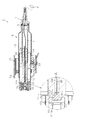
・図8に示す実施形態では、ロアシャフト12には、その一端から他端側へ延び、且つ凹部12c内に連通する貫通孔12dが形成されている。また、ワイヤ90の一端には第1連結部83に代えて、第3連結部91が設けられている。図8において拡大して示すように、第3連結部91は円柱状をなすとともに、貫通孔12dの他端開口部121dに圧入される圧入部91aと、圧入部91aよりも大径をなす当接部91bとからなる。圧入部91aの直径は、貫通孔12dの他端開口部121dの内径よりも僅かに大きくなっている。当接部91bにおける圧入部91a側の端面911bは、凹部12cの底面121cに当接可能になっている。圧入部91aは、貫通孔12dの他端開口部121dに、当接部91bの端面911bが凹部12cの底面121cに当接するまで強制的に押し込むことで圧入される。線材92の他端は、圧入部91aに対して抜け止めされた状態で圧入部91aに連結されている。このように、ロアシャフト12の他端とアッパシャフト11の一端とをワイヤ90により連結するようにしてもよい。これによれば、ワイヤ90の両端におけるアッパシャフト11及びロアシャフト12に対する連結部位が、圧入により連結されるため、係止による連結に比べて、ワイヤ90の両端におけるアッパシャフト11及びロアシャフト12に対する連結力を向上させることができる。
In addition, the said embodiment can also be implemented in the following aspects which changed this suitably.
In the embodiment shown in FIG. 8, the
・上記実施形態において、アウタチューブ13とインナチューブ14とをステアリングコラム6内に配設される連結部材により連結させてもよい。
・上記実施形態において、ロアシャフト12とアウタチューブ13とをステアリングコラム6内に配設される連結部材により連結させてもよい。
In the above embodiment, the
In the above embodiment, the
・上記実施形態において、アッパシャフト11とインナチューブ14とをステアリングコラム6内に配設される連結部材により連結させてもよい。
・上記実施形態では、連結部材として、金属製の線材82と、線材82の一端に設けられる第1連結部83と、線材82の他端に設けられる第2連結部84とから構成されたワイヤ81を用いたが、これに限らない。例えば、紐や縄等からなる線材と、この線材の一端に設けられた第1連結部83と、線材の他端に設けられる第2連結部84とから構成される連結部材を用いてもよい。
In the above embodiment, the
In the above-described embodiment, the connecting member includes a
・上記実施形態において、ワイヤは、複数本の線材82と、各線材82の一端が纏められて抜け止めされた状態で連結される第1連結部83と、各線材82の他端が纏められて抜け止めされた状態で連結される第2連結部84とから構成されていてもよい。
In the above embodiment, the wire is composed of a plurality of
・上記実施形態では、ワイヤ81における第1連結部83の係止部83bをロアシャフト12の係止凹部12bに係止させることで、第1連結部83とロアシャフト12の一端とを連結し、第2連結部84の圧入部84aをアッパシャフト11の一端開口部11bに圧入することで、第2連結部84とアッパシャフト11の一端とを連結した。しかし、これに限らず、例えば、連結部材とロアシャフト12とを連結するため、又は連結部材とアッパシャフト11とを連結するために、ブラケット、ボルト及びナット等を用いてもよい。
In the above embodiment, the first connecting
・上記実施形態において、ステアリング装置1は、鉛直方向におけるステアリング位置の調整を可能とするチルト調整機能、及びステアリングシャフト3の軸線方向におけるステアリング位置の調整を可能とするテレスコ調整機能を有していたが、これに限らず、テレスコ調整機能のみを有していてもよい。
In the above embodiment, the
・上記実施形態において、ステアリング装置1を、例えば、所謂ラックアシスト式等、コラムアシスト以外のEPSや油圧式のパワーステアリング装置、或いはノンアシスト型のステアリング装置に適用してもよい。
In the above embodiment, the
次に、上記各実施形態及び別例から把握できる技術的思想について以下に追記する。
(イ)請求項1〜請求項3のいずれか一項に記載のステアリング装置において、前記第1連結部には、前記ロアシャフトの一端に設けられる係止凹部に係止可能な係止部が設けられ、前記第2連結部には前記アッパシャフトの一端開口部に圧入される圧入部が設けられていることを特徴とするステアリング装置。
Next, the technical idea that can be grasped from the above embodiments and other examples will be described below.
(A) In the steering apparatus according to any one of
1…ステアリング装置、2…ステアリングホイール、3…ステアリングシャフト、6…ステアリングコラム、11…移動部材の一部を構成するアッパシャフト、11b…一端開口部、12…固定部材の一部を構成するロアシャフト、12b…係止凹部、13…移動部材の一部を構成するアウタチューブ、14…固定部材の一部を構成するインナチューブ、24…取付ステー、32…テレスコピック機構を構成するコラム側ブラケット、33…テレスコピック機構を構成する支軸、42…テレスコピック機構を構成するテレスコ長孔、51…ロック機構、81,90…連結部材としてのワイヤ、82,92…線材、83…第1連結部、83b…係止部、84…第2連結部、84a…圧入部。
DESCRIPTION OF
Claims (3)
前記固定部材と前記移動部材とが前記ステアリングコラム内に配設される連結部材によって連結されていることを特徴とするステアリング装置。 A steering shaft to which a steering wheel is coupled; and a steering column that rotatably supports the steering shaft. The steering shaft and the steering column are fixed to a vehicle body; and A telescopic mechanism capable of adjusting the steering position of the steering wheel in the vehicle front-rear direction by the relative movement of the moving member relative to the fixed member; In a steering device having a lock mechanism that holds the steering position of the steering wheel in the longitudinal direction of the vehicle,
The steering device, wherein the fixed member and the moving member are connected by a connecting member disposed in the steering column.
前記固定部材は、前記ステアリングシャフトのロアシャフト、及び前記ステアリングコラムのインナチューブであり、
前記移動部材は、前記ステアリングシャフトのアッパシャフト、及び前記アッパシャフトと一体的に相対移動可能な前記ステアリングコラムのアウタチューブであり、
前記連結部材は、線材と、前記線材の一端に設けられるとともに前記ロアシャフトに連結される第1連結部と、前記線材の他端に設けられるとともに前記アッパシャフトに連結される第2連結部とからなることを特徴とするステアリング装置。 The steering apparatus according to claim 1, wherein
The fixing member is a lower shaft of the steering shaft and an inner tube of the steering column;
The moving member is an upper shaft of the steering shaft, and an outer tube of the steering column that is relatively movable integrally with the upper shaft,
The connecting member includes a wire, a first connecting portion provided at one end of the wire and connected to the lower shaft, and a second connecting portion provided at the other end of the wire and connected to the upper shaft. A steering device comprising:
前記連結部材は、前記移動部材が前記固定部材から抜けない長さであり、且つ前記テレスコピック機構による前記ステアリングホイールにおける車両前後方向のステアリング位置を調整可能な長さに設定されていることを特徴とするステアリング装置。 In the steering device according to claim 1 or 2,
The connecting member has a length that prevents the moving member from coming out of the fixed member, and is set to a length that can adjust a steering position in the vehicle front-rear direction of the steering wheel by the telescopic mechanism. Steering device.
Priority Applications (1)
| Application Number | Priority Date | Filing Date | Title |
|---|---|---|---|
| JP2011030933A JP5772042B2 (en) | 2011-02-16 | 2011-02-16 | Steering device |
Applications Claiming Priority (1)
| Application Number | Priority Date | Filing Date | Title |
|---|---|---|---|
| JP2011030933A JP5772042B2 (en) | 2011-02-16 | 2011-02-16 | Steering device |
Publications (2)
| Publication Number | Publication Date |
|---|---|
| JP2012166751A true JP2012166751A (en) | 2012-09-06 |
| JP5772042B2 JP5772042B2 (en) | 2015-09-02 |
Family
ID=46971323
Family Applications (1)
| Application Number | Title | Priority Date | Filing Date |
|---|---|---|---|
| JP2011030933A Expired - Fee Related JP5772042B2 (en) | 2011-02-16 | 2011-02-16 | Steering device |
Country Status (1)
| Country | Link |
|---|---|
| JP (1) | JP5772042B2 (en) |
Cited By (1)
| Publication number | Priority date | Publication date | Assignee | Title |
|---|---|---|---|---|
| JP2014144679A (en) * | 2013-01-28 | 2014-08-14 | Nsk Ltd | Steering device |
Citations (6)
| Publication number | Priority date | Publication date | Assignee | Title |
|---|---|---|---|---|
| JPS55156766A (en) * | 1979-05-22 | 1980-12-06 | Nippon Seiko Kk | Position adjuster for steering wheel |
| JPS61190031U (en) * | 1985-05-20 | 1986-11-27 | ||
| JP2001322552A (en) * | 2000-05-16 | 2001-11-20 | Toyota Motor Corp | Tilt and telescopic steering system |
| JP2008213521A (en) * | 2007-02-28 | 2008-09-18 | Jtekt Corp | Steering device |
| JP2010111299A (en) * | 2008-11-07 | 2010-05-20 | Toyota Motor Corp | Steering force transmission device for vehicle |
| JP2010126038A (en) * | 2008-11-28 | 2010-06-10 | Toyota Motor Corp | Steering column structure |
-
2011
- 2011-02-16 JP JP2011030933A patent/JP5772042B2/en not_active Expired - Fee Related
Patent Citations (6)
| Publication number | Priority date | Publication date | Assignee | Title |
|---|---|---|---|---|
| JPS55156766A (en) * | 1979-05-22 | 1980-12-06 | Nippon Seiko Kk | Position adjuster for steering wheel |
| JPS61190031U (en) * | 1985-05-20 | 1986-11-27 | ||
| JP2001322552A (en) * | 2000-05-16 | 2001-11-20 | Toyota Motor Corp | Tilt and telescopic steering system |
| JP2008213521A (en) * | 2007-02-28 | 2008-09-18 | Jtekt Corp | Steering device |
| JP2010111299A (en) * | 2008-11-07 | 2010-05-20 | Toyota Motor Corp | Steering force transmission device for vehicle |
| JP2010126038A (en) * | 2008-11-28 | 2010-06-10 | Toyota Motor Corp | Steering column structure |
Cited By (1)
| Publication number | Priority date | Publication date | Assignee | Title |
|---|---|---|---|---|
| JP2014144679A (en) * | 2013-01-28 | 2014-08-14 | Nsk Ltd | Steering device |
Also Published As
| Publication number | Publication date |
|---|---|
| JP5772042B2 (en) | 2015-09-02 |
Similar Documents
| Publication | Publication Date | Title |
|---|---|---|
| JP5528868B2 (en) | Steering device | |
| JP5708838B2 (en) | Steering device | |
| JP6142967B2 (en) | Telescopic steering device | |
| JP6429077B2 (en) | Steering device | |
| JP2003276614A (en) | Steering device | |
| JP6417796B2 (en) | Steering device | |
| JP4683456B2 (en) | Steering device | |
| JP3591284B2 (en) | Swing support device for steering column for tilt type steering device | |
| JP2012111493A (en) | Steering device | |
| JP5737456B2 (en) | Steering column and telescopic steering device | |
| JP2012011837A (en) | Steering column apparatus | |
| JP2005014886A (en) | Steering device | |
| JP2012250651A (en) | Steering device | |
| JP5614290B2 (en) | Steering device | |
| JP5772042B2 (en) | Steering device | |
| JP2004009920A (en) | Impact-absorbing steering device | |
| JP7310166B2 (en) | steering column device | |
| JP2011046310A (en) | Vehicular steering device | |
| JP2013018397A (en) | Steering device | |
| JP5181580B2 (en) | Steering device | |
| JP2014156225A (en) | Vehicle steering device | |
| WO2020075639A1 (en) | Steering column and steering device | |
| JP2008195317A (en) | Vehicle steering device | |
| JP2019038440A (en) | Electric steering column device | |
| JP2014008881A (en) | Vehicle steering device |
Legal Events
| Date | Code | Title | Description |
|---|---|---|---|
| A621 | Written request for application examination |
Free format text: JAPANESE INTERMEDIATE CODE: A621 Effective date: 20140123 |
|
| A977 | Report on retrieval |
Free format text: JAPANESE INTERMEDIATE CODE: A971007 Effective date: 20141024 |
|
| A131 | Notification of reasons for refusal |
Free format text: JAPANESE INTERMEDIATE CODE: A131 Effective date: 20141202 |
|
| A521 | Written amendment |
Free format text: JAPANESE INTERMEDIATE CODE: A523 Effective date: 20150123 |
|
| TRDD | Decision of grant or rejection written | ||
| A01 | Written decision to grant a patent or to grant a registration (utility model) |
Free format text: JAPANESE INTERMEDIATE CODE: A01 Effective date: 20150602 |
|
| A61 | First payment of annual fees (during grant procedure) |
Free format text: JAPANESE INTERMEDIATE CODE: A61 Effective date: 20150615 |
|
| R150 | Certificate of patent or registration of utility model |
Ref document number: 5772042 Country of ref document: JP Free format text: JAPANESE INTERMEDIATE CODE: R150 |
|
| LAPS | Cancellation because of no payment of annual fees |