JP2012166370A - Cooling processing apparatus - Google Patents
Cooling processing apparatus Download PDFInfo
- Publication number
- JP2012166370A JP2012166370A JP2011027144A JP2011027144A JP2012166370A JP 2012166370 A JP2012166370 A JP 2012166370A JP 2011027144 A JP2011027144 A JP 2011027144A JP 2011027144 A JP2011027144 A JP 2011027144A JP 2012166370 A JP2012166370 A JP 2012166370A
- Authority
- JP
- Japan
- Prior art keywords
- cooling
- temperature
- processing
- heating
- surface portion
- Prior art date
- Legal status (The legal status is an assumption and is not a legal conclusion. Google has not performed a legal analysis and makes no representation as to the accuracy of the status listed.)
- Withdrawn
Links
Images
Landscapes
- Moulds For Moulding Plastics Or The Like (AREA)
Abstract
【課題】処理面を均等に温度調整する。
【解決手段】被処理物を冷却処理する処理面2aを有する処理体2内に冷却部3を設け、冷却部3によって冷却されて生じる処理面1aにおける高温部分と低温部分との内の、低温部分の近くの処理体2内に加熱部4Aを配置する。
【選択図】図1The temperature of a processing surface is adjusted uniformly.
A cooling unit 3 is provided in a processing body 2 having a processing surface 2a for cooling an object to be processed, and a low temperature in a high temperature portion and a low temperature portion in a processing surface 1a generated by cooling by the cooling unit 3 is provided. 4 A of heating parts are arrange | positioned in the processing body 2 near a part.
[Selection] Figure 1
Description
本発明は、冷却処理装置が有する処理面の温度管理に関する。 The present invention relates to temperature management of a processing surface of a cooling processing apparatus.
被処理物に各種の処理を施す処理体を備える装置構成では、被処理物に接する処理体の処理面を均等に温度調整することが重要となる。そこで従来から、上記装置構成では、処理面近傍の処理体に冷却部を埋設し、この冷却部によって処理面の表面温度を調整する冷却処理装置を備えたものがある。 In an apparatus configuration including a processing body that performs various types of processing on a workpiece, it is important to uniformly adjust the temperature of the processing surface of the processing body in contact with the workpiece. In view of this, some of the above-described apparatus configurations conventionally include a cooling processing apparatus in which a cooling unit is embedded in a processing object near the processing surface and the surface temperature of the processing surface is adjusted by the cooling unit.
しかしながら、冷却部によって処理面の表面温度を調整する従来例では、処理面の表面を均等に温度管理し難いという課題があった。これは特に冷却のために温度を急激に変化させる際により顕著となる。すなわち、冷却部に近接する処理面の表面部位(以下、第1の表面部位という)と冷却部との間の部位における熱容量と、第1の表面部位以外の表面部位(以下、第2の表面部位という)と冷却部との間における熱容量とを比較すると、前者の方が小さい。これは、第1の表面部位と冷却部との間の離間距離と、第2の表面部位と冷却部との間の離間距離とを比較すれば理解できる。このような熱容量の相違があるために、冷却部で温度調整を実施しても、第2の表面部位に比して第1の表面部位は温度の変化量が大きくなり、その結果、処理面に温度斑が生じる。 However, the conventional example in which the surface temperature of the processing surface is adjusted by the cooling unit has a problem that it is difficult to uniformly control the temperature of the processing surface. This is particularly noticeable when the temperature is changed rapidly for cooling. That is, the heat capacity in a portion between the surface portion of the processing surface adjacent to the cooling portion (hereinafter referred to as the first surface portion) and the cooling portion, and the surface portion other than the first surface portion (hereinafter referred to as the second surface). Comparing the heat capacity between the cooling part and the former), the former is smaller. This can be understood by comparing the separation distance between the first surface portion and the cooling portion and the separation distance between the second surface portion and the cooling portion. Due to such a difference in heat capacity, even if the temperature adjustment is performed in the cooling section, the amount of change in the temperature of the first surface portion is larger than that of the second surface portion. Temperature spots occur.
本発明は、このような課題を解決するためになされたものであって、処理体の処理面を均等に温度調整することを主たる目的とする。 The present invention has been made in order to solve such a problem, and a main object thereof is to uniformly adjust the temperature of the treatment surface of the treatment body.
本発明は、以下の構成を備える。 The present invention has the following configuration.
(1)本発明は、
被処理物を冷却処理する処理面を有する処理体と、該処理体内に設けられて前記処理面を冷却する冷却部とを備える冷却処理装置であって、
前記冷却部によって冷却されて生じる前記処理面における高温部分と低温部分の内、前記低温部分の近くの前記処理体内に、加熱部を配置する。
(1) The present invention
A cooling processing apparatus comprising: a processing body having a processing surface for cooling a workpiece; and a cooling unit provided in the processing body for cooling the processing surface,
A heating part is arranged in the processing body near the low temperature part among a high temperature part and a low temperature part in the processing surface that is generated by being cooled by the cooling part.
前述したように、冷却部に近接する第1の表面部位と冷却部との間の熱容量は、第1の表面部位以外の第2の表面部位と冷却部との間の熱容量より小さい。そのため、第1の表面部位は、第2の表面部位に比して過度に冷却されてしまう可能性がある。この場合、第1の表面部位が低温部分となり、第2の表面部位が高温部分となる。そこで、(1)の構成では、低温部分の近くの前記処理体内に加熱部を配置することで、低温部分(第1の表面部位)の過冷却を抑制している。これにより、処理面の温度斑が生じにくくなる。 As described above, the heat capacity between the first surface portion adjacent to the cooling portion and the cooling portion is smaller than the heat capacity between the second surface portion other than the first surface portion and the cooling portion. Therefore, there is a possibility that the first surface portion is excessively cooled as compared with the second surface portion. In this case, the first surface portion is a low temperature portion, and the second surface portion is a high temperature portion. Therefore, in the configuration of (1), the supercooling of the low temperature portion (first surface portion) is suppressed by arranging the heating unit in the processing body near the low temperature portion. This makes it difficult for temperature spots to occur on the treated surface.
(2)上記(1)の構成において、前記高温部分の近くの前記処理体内にもう一つの加熱部をさらに配置する、という実施の形態がある。これにより、両加熱部による処理体への加熱処理を個別に制御することで、高温部分(第1の表面部位)と、低温部分(第2の表面部位)とにおける相対的な温度調整を精度高く行うことができる。これにより、処理面の温度斑がさらに生じにくくなる。 (2) In the configuration of (1), there is an embodiment in which another heating unit is further arranged in the processing body near the high temperature portion. Thereby, the relative temperature adjustment in a high temperature part (1st surface site | part) and a low temperature part (2nd surface site | part) is carried out by controlling individually the heat processing to the process body by both heating parts. Can be done high. As a result, temperature spots on the treated surface are less likely to occur.
(3)上記(1)の構成において、前記加熱部に代えて、前記低温部分の近くの前記処理体内に断熱体を配置する、という実施の形態がある。 (3) In the configuration of (1), there is an embodiment in which a heat insulator is disposed in the processing body near the low temperature portion instead of the heating unit.
上記(3)では、冷却部による低温部(第1の表面部位)に対する冷却を断熱体によって抑制することで、低温部分(第1の表面部位)の過冷却を防止している。これにより、処理面の温度斑が生じにくくなる。 In said (3), the cooling with respect to the low temperature part (1st surface site | part) by a cooling unit is suppressed by a heat insulator, and the overcooling of the low temperature part (1st surface site | part) is prevented. This makes it difficult for temperature spots to occur on the treated surface.
上記(1)〜(3)の構成において、前記冷却部は、前記処理面に沿って前記処理体の内部に設けられた冷却管であるのが好ましい。 In the configurations of (1) to (3), the cooling unit is preferably a cooling pipe provided inside the processing body along the processing surface.
上記(1)〜(4)の構成において、前記冷却部は冷却液によって冷却され、冷却開始前の前記処理体の一部または全部の温度は前記冷却液の沸点以上であるのが好ましい。これにより次のような作用効果が得られる。処理面における温度斑が大きく問題となるのは、通常より高温となる状態からの冷却を行う冷却処理装置(例えば、一般にヒート&クールと呼ばれるような手法に用いる樹脂成形用金型)である。すなわち、例えば一般的な射出成形用金型等は通常、100℃以下の一定温度(樹脂が固化/脱型可能な温度)に保持された状態で用いられるが、ヒート&クール用金型等の一部の樹脂成形用金型(処理体)では、樹脂の溶融温度を超える、または溶融温度以下であっても固化が完全に進まない高温(例えば100〜250℃等)に保持されたのち樹脂が固化/脱型可能な温度域まで急速に冷却されることが多い。このような高温域まで昇温される処理体を冷却する冷却処理装置の冷却部を、冷却液によって冷却される構成にし、さらに冷却開始前の処理体の一部または全部の温度が冷却液の沸点以上となるようにすると、冷却開始前の状態で冷却液は気化状態になる。そのため、冷却を開始すると冷却液の気化熱によって処理面は急速に冷却される。この構成では、急速冷却が可能になるものの、冷却後の処理面における温度斑が顕著になりやすい。何らかの手法を用い全体的な冷却速度を遅くすることで温度斑を抑制することは可能ではあるが、これでは例えば樹脂成形に要するサイクルタイムが長くなってしまい、工業的に推奨されない。これに対して、上述した本発明の基本構成(低温部分の近くの処理体内に、加熱部を配置する構成)を設けることで、冷却能力の高い冷却液の気化を用いると共に、このような顕著な温度斑も精度高く防止されることになる。 In the above configurations (1) to (4), it is preferable that the cooling unit is cooled by a cooling liquid, and the temperature of a part or all of the treatment body before the start of cooling is equal to or higher than the boiling point of the cooling liquid. As a result, the following effects can be obtained. It is a cooling processing apparatus (for example, a resin molding die generally used for a technique called heat & cool) that performs cooling from a temperature higher than usual, which causes a problem of temperature unevenness on the processing surface. That is, for example, a general injection mold or the like is usually used in a state of being maintained at a constant temperature of 100 ° C. or less (a temperature at which the resin can be solidified / demolded). In some resin molding dies (processed bodies), the resin after being held at a high temperature (for example, 100 to 250 ° C.) at which solidification does not proceed completely even when the melting temperature of the resin is exceeded or below the melting temperature Is often rapidly cooled to a temperature range in which it can be solidified / demolded. The cooling unit of the cooling processing apparatus that cools the processing body heated to such a high temperature region is configured to be cooled by the cooling liquid, and the temperature of a part or all of the processing body before the cooling starts When the boiling point is exceeded, the cooling liquid is in a vaporized state before the start of cooling. Therefore, when cooling is started, the processing surface is rapidly cooled by the heat of vaporization of the coolant. With this configuration, although rapid cooling is possible, temperature spots on the treated surface after cooling tend to be noticeable. Although it is possible to suppress temperature fluctuations by slowing the overall cooling rate using some method, this increases the cycle time required for resin molding, for example, and is not industrially recommended. On the other hand, by providing the basic configuration of the present invention described above (a configuration in which the heating unit is arranged in the processing body near the low temperature portion), the vaporization of the coolant having a high cooling capacity is used, and such a remarkable Therefore, accurate temperature spots can be prevented with high accuracy.
なお、本発明は、
被処理物を冷却処理する処理面を有する処理体と、該処理体内に設けられて前記処理面を冷却する冷却部とを備える冷却処理装置であって、
前記冷却部によって冷却されて生じる前記処理面における高温部分と低温部分の内、前記高温部分の近くの前記処理体内に、熱伝導体を配置する、
という構成にしてもよい。
In the present invention,
A cooling processing apparatus comprising: a processing body having a processing surface for cooling a workpiece; and a cooling unit provided in the processing body for cooling the processing surface,
A thermal conductor is disposed in the processing body near the high temperature portion among the high temperature portion and the low temperature portion in the processing surface that is generated by being cooled by the cooling section.
It may be configured as follows.
この構成では、高温部分(第2の表面部位)の冷却を、熱伝導体によって促進することで、低温部分(第1の表面部位)の過冷却を防止することができ、これによっても処理面の温度斑が生じにくくなる。 In this configuration, the cooling of the high-temperature portion (second surface portion) is promoted by the heat conductor, so that the overcooling of the low-temperature portion (first surface portion) can be prevented. Temperature spots are less likely to occur.
また、本発明は、
被処理物を冷却処理する処理面を有する処理体と、該処理体内に設けられて前記処理面を冷却する冷却部とを備える冷却処理装置であって、
前記冷却部によって冷却されて生じる前記処理面における高温部分と低温部分の内、前記高温部分の近くの前記処理体に切欠を形成してもよい。
The present invention also provides:
A cooling processing apparatus comprising: a processing body having a processing surface for cooling a workpiece; and a cooling unit provided in the processing body for cooling the processing surface,
A notch may be formed in the processing body near the high temperature portion among the high temperature portion and the low temperature portion on the processing surface generated by being cooled by the cooling section.
この構成では、切欠を設けることにより、高温部分となる第2の表面部位の熱容量が小さくなって、高温部分(第2の表面部位)の冷却が促進される。これにより、低温部分(第1の表面部位)の過冷却を防止することができる。これによっても処理面の温度斑が生じにくくなる。 In this configuration, by providing the notch, the heat capacity of the second surface portion that becomes the high temperature portion is reduced, and cooling of the high temperature portion (second surface portion) is promoted. Thereby, overcooling of a low-temperature part (1st surface site | part) can be prevented. This also makes it difficult to produce temperature spots on the treated surface.
なお、以上、本発明の利用について樹脂成形の場合について多く言及しているが、本発明はこの用途に限るものではない。また成形に用いる場合にその成形法は限定されず、射出成形、射出プレス成形、プレス成形、オートクレーブ成形、ダイヤフラム成形、その他温度制御が必要な治具・熱板、金型類に広く活用することができる。これらの内、ヒート&クールと呼ばれる急速冷却が必要な手法との組み合わせは、本発明を有効に活用するのに好適な例である。被処理物としては、熱可塑性樹脂や熱硬化性樹脂(それぞれ各種フィラーや強化繊維を含有していてもよい)の他、金属、半導体、各種繊維素材の織物やマットなどの不織布基材、その他例えば温度による反応を伴う化学物質などを例示することができる。被処理物に温度変化を与えることで、その相変化などにより形態を変化(成形、賦型)させることや、その化学変化により機能を変化させることが必要であり、特に急速に冷却することが工業的に有効な場合において、本発明を広く活用することが可能である。 As mentioned above, the use of the present invention is often referred to in the case of resin molding, but the present invention is not limited to this application. In addition, the molding method is not limited when used for molding, and it is widely used for injection molding, injection press molding, press molding, autoclave molding, diaphragm molding, and other jigs, hot plates and molds that require temperature control. Can do. Among these, a combination with a technique that requires rapid cooling called heat and cool is a suitable example for effectively utilizing the present invention. Examples of objects to be processed include thermoplastic resins and thermosetting resins (each may contain various fillers and reinforcing fibers), non-woven substrates such as metals, semiconductors, various textile materials and mats, etc. For example, a chemical substance accompanied by a reaction due to temperature can be exemplified. It is necessary to change the form (molding, shaping) due to the phase change, etc. by changing the temperature of the workpiece, and to change the function due to the chemical change. In the case of being industrially effective, the present invention can be widely used.
本発明は、処理面の冷却前の温度から、冷却完了後の温度の差が大きい場合に特に有効である。温度範囲について制約はないが、通常の手法では処理面の温度斑が大きくなってしまう温度差50℃以上の場合、特に温度差100℃以上の場合に本発明は有効である。実温度については処理体に対してどのような処理が必要かに応じて決定される。冷却前の処理面の温度は通常100〜250℃が用いられるが、例えばスーパーエンプラと称されるポリマー類であるPEI(ポリエーテルイミド)、PPS(ポリフェニレンサルファイト)、PEEK(ポリエーテルエーテルケトン)、PEKK(ポリエーテルケトンケトン)などは、その耐熱性の高さから処理面温度300〜400℃が求められる場合もある。これを温度差100℃以上急速冷却する際には、特に温度斑抑制が課題になり、本発明が有効である。 The present invention is particularly effective when the difference between the temperature of the treated surface before cooling and the temperature after completion of cooling is large. Although there is no restriction on the temperature range, the present invention is effective when the temperature difference is 50 ° C. or more, in particular, when the temperature difference is 100 ° C. or more, in which the temperature unevenness of the processing surface becomes large by a normal method. The actual temperature is determined according to what kind of processing is required for the processing body. The temperature of the treated surface before cooling is usually 100 to 250 ° C. For example, PEI (polyetherimide), PPS (polyphenylene sulfite), and PEEK (polyether ether ketone) are polymers called super engineering plastics. , PEKK (polyetherketone ketone) and the like may require a treatment surface temperature of 300 to 400 ° C. due to its high heat resistance. When this is rapidly cooled by a temperature difference of 100 ° C. or more, temperature spot suppression is particularly a problem, and the present invention is effective.
例えば樹脂成形時の例を挙げると、冷却時の温度斑が生じると、被処理物(成形品)に局部的なひずみが生じたり、樹脂の種類によっては固化時の結晶化度が冷却速度によって変化し、局部的収縮によるひずみ発生の他に、表面品位が変化する、樹脂靱性が変化するなど、様々な問題を生じる。本発明によれば、処理面の温度斑が生じなくなって、均等な表面温度を得ることができる。その結果、被処理物が均等に冷却されるようになり、被処理物の欠陥、品位低下などの問題を抑制することができる。 For example, when an example of resin molding is given, if temperature spots occur during cooling, local distortion occurs in the workpiece (molded product), or the degree of crystallization during solidification depends on the cooling rate depending on the type of resin. In addition to the generation of strain due to local shrinkage, various problems such as surface quality change and resin toughness change occur. According to the present invention, temperature unevenness on the treated surface does not occur, and a uniform surface temperature can be obtained. As a result, the object to be processed is cooled evenly, and problems such as defects in the object to be processed and deterioration in quality can be suppressed.
以下、本発明の各実施の形態を説明する。なお、各実施の形態の冷却処理装置は、図示しない被処理物(溶融状態の樹脂等)を加熱/加圧処理等の処理を実施する際において、その処理の途中で被処理物を冷却する際に用いられる装置である。 Each embodiment of the present invention will be described below. In addition, the cooling processing apparatus of each embodiment cools a to-be-processed object in the middle of the process, when processing to-be-processed object (molten resin etc.) which is not shown in figure is heated / pressurized process etc. It is a device used at the time.
(実施の形態1)
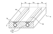
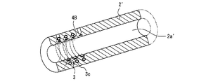
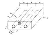
図1は、本発明の実施の形態1の冷却処理装置1Aの要部を示す一部切欠斜視図である。冷却処理装置1Aは処理体2を備えている。処理体2は金属等の良伝熱体からなり平板形状を有している。図中上側に位置する処理体2の表面は、図示しない被処理物(溶融状態の樹脂等)が接触する処理面2aとなっている。処理面2aにおいては、該処理面2aに接触する被処理物に冷却処理が実施される。なお、処理体2は、被処理物を処理面2a上に載置して保持する構成であってもよいし、処理面2aを内面にして閉じた容器(金型やシリンダ等)を構成することで被処理物を容器内で保持する構成であってもよい。
(Embodiment 1)
FIG. 1 is a partially cutaway perspective view showing a main part of a
処理体2は冷却部3と加熱体4Aとを備えている。冷却部3と加熱体4Aとは処理体2に埋設されている。冷却部3は、処理体2内において処理面2aに部分的に向い合った状態で配置される。具体的には冷却部3は、処理体2の内部に、処理面2aに沿って貫通して配置された冷却管3a、3bから構成されている。冷却管3a、3bは互いに並列配置されている。冷却管3a、3bを設けるために処理体2には、冷却管3a、3bと同形状の貫通孔が形成されている。なお、図中、冷却管3a、3bは2管設けられているが、3管以上であってもよいし、単一管であってもよい。また、冷却管3a、3bに換えて、処理体2に貫通孔を設けてもよい。
The
本実施の形態において、冷却管3a、3bには温度調整媒体が流通する。温度調整媒体として、例えば、冷却液(水、アルコール等)が挙げられる。冷却管3a、3bに冷却液等の温度調整媒体を流通させることで、処理面2aを介して被処理物が冷却される。
In the present embodiment, a temperature adjusting medium flows through the cooling
加熱体4Aは、長板状の加熱ヒータ(電熱ヒータ等)からなり、冷却管3a、3bに近接する処理面2aの第1の表面部位2a1、2a1と冷却管3a、3bとの間に設けられる。長板状の加熱体4Aは、冷却管3a、3bに沿って配置される。
以下、冷却処理装置1Aが処理面2aを介して被処理物に実施する冷却処理を説明する。なお、以下の説明では、・被処理物から熱を受ける、・他の加熱手段による加熱処理を受ける、等の理由により高温になった処理面2aを所定の温度まで冷却することで、被処理物を冷却する処理を実施する場合を想定して、本実施の形態における冷却処理を説明する。
Hereinafter, the cooling process which 1 A of cooling processing apparatuses implement to a to-be-processed object through the
処理面2aの近傍がt1℃まで高温状態となった処理体2を冷却するために、冷却管3a、3bにt2℃(t2<t1)の温度調整媒体を流通させることで、処理面2aの近傍を冷却する。ここで、処理体2の表面部位それぞれと冷却管3a、3bとの間の領域における熱容量は、表面各部位と冷却管3a、3bとの間の離間距離に比例して大きくなる。このような熱容量の変化があるため、冷却部3による所定時間の冷却処理を経た処理体2の表面部位それぞれが到達する表面温度は、冷却管3a、3bとの間の離間距離に反比例する。具体的には、図2に示すように、処理面2aの表面部位を、冷却管3a、3bに近接する処理面2aの第1の表面部位2a1と、第1の表面部位2a1以外の処理面2aの第2の表面部位2a2とに区分した場合、冷却部3による所定時間の冷却処理を経て第1の表面部位2a1が到達する温度をT1とし、第2の表面部位2a2が到達する温度をT2とすると、T1<T2となる。つまり、第1の表面部位2a1は第2の表面部位2a2に比して過冷却状態となる。その結果、第1の表面部位2a1は低温部分となり、第2の表面部位2a2は高温部分となる。しかしながら、これでは、冷却処理を経た処理面2aの表面温度に温度斑が生じてしまう。
In order to cool the
本実施の形態では、このような温度斑を解消するために、加熱体4Aを設けており、第2の表面部位2a2(高温部分)に比して過冷却状態となる第1の表面部位2a1(低温部分)を含むその近傍を加熱体4Aによって加熱して温度を上昇させる。温度上昇量は、以下のように設定される。すなわち、冷却部3による冷却処理を経て第1の表面部位2a1が到達する表面温度と、第2の表面部位2a2が到達する表面温度とが可及的に均等になるように、上記温度上昇量は設定される。これにより、冷却処理を経た処理面2aの表面温度は全面でほぼ均等になって温度斑が生じにくくなる。
In the present embodiment, in order to eliminate such temperature spots, the
なお、加熱体4Aとしては、図1に示す平板形状の加熱体4Aの他、図3に示すように、シーズヒータ等の丸棒形状の加熱体4A’でもよい。また、冷却部3としては、図1に示す直線状の冷却管3a、3bを並列配置した構成の他、図4に示すように、コの字等の任意の屈曲形状にした1本の冷却管3cから冷却部3を構成してもよい。図4の構成では、任意の屈曲形状にした1本の冷却管3cに応じた同等の形状を有する加熱部4A’’が設けられている。また、処理体2は、図1に示すような平板形状だけでなく、図5に示す円筒2’であってもよい。その場合は、円筒2’の内部に被処理物が収納され、円筒2’の内周面2a’が処理面となり、冷却部3を構成する冷却管3cと加熱体4Bとは螺旋状に配置されて円筒2’に埋設される。なお、図3〜図5に示す実施の形態1の変形例は、実施の形態1のみならず、以下に説明する他の実施の形態においても同様に実施可能である。
In addition to the flat plate-shaped
本実施の形態では、冷却部3は冷却液によって冷却されるが、さらに冷却開始前の処理体2の一部または全部の温度は、冷却液の沸点以上となっている。処理面における温度斑が大きく問題となるのは、通常より高温となる状態からの冷却を行う冷却処理装置(例えば、一般にヒート&クールと呼ばれるような手法に用いる樹脂成形用金型)である。すなわち、例えば一般的な射出成形用金型等は通常、100℃以下の一定温度(樹脂が固化/脱型可能な温度)に保持された状態で用いられるが、ヒート&クール用金型等の一部の樹脂成形用金型(処理体2)では、樹脂の溶融温度を超える、または溶融温度以下であっても固化が完全に進まない高温(例えば100〜250℃等)に保持されたのち樹脂が固化/脱型可能な温度域まで急速に冷却されることが多い。このような高温域まで昇温される処理体2を冷却する冷却処理装置3を、冷却液によって冷却される構成にしさらに冷却開始前の処理体の一部または全部の温度が冷却液の沸点以上となるようにすると、冷却開始前の状態で冷却液は気化状態になる。そのため、冷却を開始すると冷却液の気化熱によって処理面2aは急速に冷却される。本実施の形態では、このような理由により急速冷却が可能になるものの、冷却後の処理面2aにおける温度斑が顕著になりやすいが、低温部分の近くの処理体2内に、加熱部4Aを配置する構成を設けることで、このような顕著な温度斑も精度高く防止することができる。
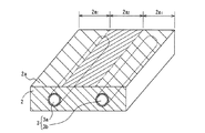
(実施の形態2)
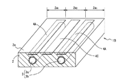
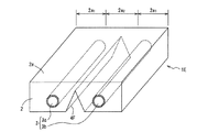
図6は、本発明の実施の形態2の冷却処理装置1Bの要部を示す一部切欠斜視図である。冷却処理装置1Bの基本構造は、実施の形態1の冷却処理装置1Aと同様である。そのため、図6および以下の説明において、実施の形態1(図1〜図5)と同一ないし同様の部分には同一の符号を付し、それらについての説明は省略する。
In the present embodiment, the
(Embodiment 2)
FIG. 6 is a partially cutaway perspective view showing the main part of the
本実施形態は、実施の形態1における加熱体4Aに加えて、もう一つの加熱体4Cを有する。加熱体4Cは、次のように配置されている。すなわち、処理面2aの表面部位を、冷却管3a、3bに近接する第1の表面部位2a1と、第1の表面部位2a1以外の第2の表面部位2a2とに区分する。なお、図6では、第2の表面部位2a2として、以下の位置の表面部位が例示されている。すなわち、冷却管3aの上方に位置する第1の表面部位2a1と、冷却管3bの上方に位置する第1の表面部位2a1との間に位置する表面部位が第2の表面部位2a2として例示されている。このように設定された第2の表面部位2a2は、第1の表面部位2a1、2a1に比して、冷却管3a、3bから離間した位置になる。
This embodiment has another
加熱部4A、4Aは、第1の表面部位2a1、2a1の近傍で、第1の表面部位2a1、2a1と冷却管3a、3bとの間に介在する状態で、処理体2に埋設されている。a加熱部4Cは、第2の表面部位2a2の近傍で、第2の表面部位2a2と冷却管3a、3bとの間に介在する状態で、処理体2に埋設されている。
本実施の形態の冷却処理装置1Bが処理面2aに実施する冷却処理について説明する。処理面2aの近傍がt1℃まで高温状態となった処理体2を冷却する場合、冷却管3a、3bにt2℃(t1>t2)の温度調整媒体を流通させることで、処理面2aが冷却される。このような冷却処理が実施されると、実施の形態1で説明したように、第1の表面部位2a1が第2の表面部位2a2に比して過冷却状態となる。その結果、第1の表面部位2a1が低温部分となり、第2の表面部位2a2が高温部分となって、処理面2aの表面温度に温度斑が生じてしまう。
A cooling process performed on the
本実施の形態では、このような冷却時の温度斑を解消するために、加熱体4A、74Aに加えてもう一つの加熱部4Cを設けて、冷却部3による温度調整を経た処理面2aの各表面部位が到達する表面温度が互いに可及的に均等になるように、加熱部4C、4Cそれぞれの加熱量を調整する。加熱量は、以下のように設定される。すなわち、第2の表面部位2a2に比して過冷却状態となる第1の表面部位2a1、2a1を加熱する加熱部4Aの加熱量をK1とし、第1の表面部位2a1に比して冷却不足状態となる第2の表面部位2a2を加熱する加熱部4Cの加熱量をK2とすると、K1>K2とする。その際、冷却部3による冷却処理を経た第1の表面部位2a1が到達する表面温度と、第2の表面部位2a2の表面温度とが可及的に均等になるように、K1とK2の比率(K1:K2)を設定する。これにより、冷却処理を経た処理面2aの表面温度は全面でほぼ均等になって温度斑が生じにくくなる。
In the present embodiment, in order to eliminate such temperature spots at the time of cooling, another
本実施の形態の冷却処理装置は、冷却管3a、3bにt4℃(t4>t3)となった温度調整用媒体(加熱媒体)を流通させることにより、処理面2aを加熱することで、被処理物を加熱処理する構成においても対応することができる。すなわち、本実施の形態は、加熱処理時においても、処理面2aの表面温度を均等に保持することが可能である。以下、加熱処理における表面温度調整について説明する。なお、以下の説明では、一部の部品の名称と実際の処理とが離反する(冷却管3a、3bを有する冷却部3が加熱処理を行うことになる)が、部品名称(冷却部3、冷却管3a、3b)は継続して使用する。
The cooling processing apparatus of the present embodiment heats the
処理面2aがt3℃状態となった処理体2を加熱処理する場合、冷却管3a、3bにt4℃(t4>t3)となった温度調整用媒体またはその蒸気(水蒸気等)を流通させることで、処理面2aを加熱する。このような加熱処理が実施されると、以下の理由により、処理面2aに温度斑が生じる。
When heat-treating the
処理体2の表面部位それぞれと冷却管3a、3bとの間の領域における熱容量は、実施の形態1で説明したように、表面各部位と冷却管3a、3bとの間の離間距離に比例して大きくなる。このような熱容量の変化があるため、冷却部3による所定時間の加熱処理を経た処理体2の表面部位それぞれが到達する温度は、冷却管3a、3bとの間の離間距離に反比例する。具体的には、冷却部3による所定時間の加熱処理を経て第1の表面部位2a1が到達する温度をT3とし、第2の表面部位2a2が到達する温度をT4とすると、T3>T4となる。つまり、第1の表面部位2a1は、第2の表面部位2a2に比して過加熱状態となる。その結果、第1の表面部位2a1は高温部分となり、第2の表面部位2a2は低温部分となる。しかしながら、これでは、加熱処理を経た処理面2aの表面温度に温度斑が生じてしまう。
As described in the first embodiment, the heat capacity in the region between each surface portion of the
本実施の形態では、このような加熱処理時の温度斑を解消するために、処理面2aの各表面部位が冷却部3によって加熱調整される結果到達する温度が互いに可及的に均等になるように、加熱部4A、4A、4Cそれぞれの加熱量を調整する。加熱量は、以下のように設定される。すなわち、第2の表面部位2a2に比して過加熱状態となる第1の表面部位2a1、2a1を加熱する加熱部4A、4Aの加熱量をK3とし、第1の表面部位2a1に比して加熱不足状態となる第2の表面部位2a2を加熱する加熱部4Cの加熱量をK4とすると、K3<K4とする。その際、第1の表面部位2a1が到達する表面温度と、第2の表面部位2a2が到達する表面温度とが可及的に均等になるように、K3とK4の比率(K3:K4)を設定する。これにより、加熱処理を経た処理面2aの表面温度は全面でほぼ均等になって温度斑が生じにくくなる。
In the present embodiment, in order to eliminate such temperature spots during the heat treatment, the temperatures reached as a result of the heat adjustment of each surface portion of the
なお、処理体2の処理面2a近傍を加熱する方法としては、冷却管3a、3bに温度調整媒体(蒸気等)を流通させる方法の他に、加熱部4A、4Cによって、処理面2a近傍を直接加熱する方法もある。この加熱方法は、例えば、冷却部3による処理面2a近傍の加熱/冷却処理を行ったのち、冷却部3による加熱/冷却処理を停止した状態で、処理面2a近傍の温度を微調整する際などにおいて実施される。このような加熱部4A、4Cによる直接加熱では、空孔となった冷却管3a、3bの有無を考慮する必要がある。以下、詳細に説明する。
In addition, as a method for heating the vicinity of the
処理体2の表面部位それぞれにおける熱容量は、空孔となった冷却管3a、3bの有無に応じて変化する。このような熱容量の変化があるため、加熱部4A、4Cによる所定時間の加熱処理を経た処理体2の表面部位それぞれが到達する温度は、冷却管3a、3bの有無により変化する。具体的には、加熱部4A、4Cで同一の加熱量を付与することを条件にすると、冷却管3a、3bが存在する第1の表面部位2a1(熱容量が小さい)は、冷却管3a、3bが存在しない第2の表面部位2a2(熱容量が大きい)に比して過加熱状態となる。
The heat capacity at each surface portion of the
このことを考慮して、加熱部4Aによる第1の表面部位2a1の加熱処理を経て第1の表面部位2a1が到達する表面温度と、加熱部4Cによる第2の表面部位2a2の加熱処理を経て第2の表面部位2a2が到達する表面温度とが可及的に均等になるように、加熱部4Aと加熱部4Cとの加熱出力が個別に設定される。これにより、加熱部4A、4Cによる加熱処理を経た処理面2aの表面温度は全面でほぼ均等になって温度斑が生じにくくなる。
With this in mind, the surface temperature of the
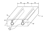
(実施の形態3)
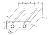
図7は、本発明の実施の形態3の冷却処理装置1Cの要部を示す一部切欠斜視図である。冷却処理装置1Cの基本構造は、実施の形態1の冷却処理装置1Aと同様である。そのため、図7および以下の説明において、実施の形態1(図1〜図5)と同一ないし同様の部分には同一の符号を付し、それらについての説明は省略する。
(Embodiment 3)
FIG. 7 is a partially cutaway perspective view showing a main part of a
本実施形態は、実施の形態1における加熱体4Aに換えて断熱体4Dを有する。断熱体4Dは、温度調整用媒体流通孔3a、3bと第1の表面部位2a1、2a1(低温部分)との間の処理体2に埋設されている。具体的には、断熱体4Dは、処理体2に穿たれて内部に空気等の断熱材が充填された断熱孔から構成される。断熱孔に充填される断熱材は、空気に限ることなく、処理体2より熱伝導率の低い材料であればどのような材料であってもよい。断熱孔は冷却管3a、3bと並行して配列される。
The present embodiment has a
本実施の形態の冷却処理装置1Cが処理面2aを介して被処理物に実施する温度調整処理は基本的に冷却処理であるが、構成を若干変えることで加熱処理を行うことも可能である。そのため、一部の部分の名称と実際の処理とが離反する(冷却管3a、3bを有する冷却部3が加熱処理を行うことになる)が、部品名称(冷却部3、冷却管3a、3b)は変更することなく継続して使用する。
The temperature adjustment process performed on the object to be processed by the cooling
処理面2aを冷却処理または加熱処理する場合、冷却管3a、3bに温度調整媒体を流通させることで、処理面2aが冷却または加熱される。このような冷却/加熱処理が実施されると、実施の形態1、2で説明したように、第1の表面部位2a1は、第2の表面部位2a2に比して過冷却状態または過加熱状態となる。つまり、冷却処理の場合は、第1の表面部位2a1が低温部分となり、第2の表面部位2a2が高温部分となる。反対に加熱処理の場合は、第1の表面部位2a1が高温部分となり、第2の表面部位2a2が低温部分となる。しかしながら、冷却処理、加熱処理いずれの処理を行っても、処理面2aの表面温度に温度斑が生じてしまう。
When the
本実施の形態では、このような冷却/加熱時の温度斑を解消するために、断熱体4Dを設けて、処理面2aの各表面部位が冷却部3によって冷却処理または加熱処理されることで到達する処理面2aの表面温度が全面的に均等になるように、第1の表面部位2a1、2a1と冷却管3a、3bとの間を断熱している。断熱体4Dの断熱能力は、以下のように設定される。すなわち、冷却部3による温度調整処理を経た第1の表面部位2a1の表面温度と、第2の表面部位2a2の表面温度とが可及的に均等になるように、断熱体4Dの断熱能力が設定されている。断熱体4Dの断熱能力は、断熱体4Dの容量や熱伝導率を調整することで任意に設定可能である。これにより、冷却/加熱処理を経た処理面2aの表面温度は全面でほぼ均等になって温度斑が生じにくくなる。
In the present embodiment, in order to eliminate such temperature spots during cooling / heating, a
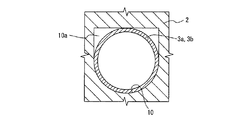
なお、断熱体4Dの設置構成としては、図7に示すような断熱孔を別途設ける構成だけでなく、図8に示すように、温度調整用媒体流通管3a、3bを設けるために処理体2に設けられる貫通孔10の形状を変更してもよい。図8では、断面円形の温度調整用媒体流通管3a、3bを設けるために通常なら断面円形に形成する貫通孔10の上側(第1の表面部位2a1、2a1側)に隙間10aを形成して、この隙間10aを断熱孔としている。
The installation structure of the
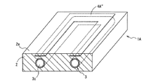
(実施の形態4)
図9は、本発明の実施の形態4の冷却処理装置1Dの要部を示す一部切欠斜視図である。冷却処理装置1Dの基本構造は、実施の形態1の冷却処理装置1Aと同様である。そのため、図9および以下の説明において、実施の形態1(図1〜図5)と同一ないし同様の部分には同一の符号を付し、それらについての説明は省略する。
(Embodiment 4)
FIG. 9 is a partially cutaway perspective view showing a main part of a
本実施形態は、実施の形態1における加熱体4Aに換えて熱伝導体4Eを有する。熱伝導体4Eは、処理体2より熱伝導率が高い材料(銅、アルミニウム、ヒートパイプ等)からなり、冷却管3a、3bと第2の表面部位2a2との間に配置された状態で処理体2に埋設されている。熱伝導体4Eは、焼きばめ、鋳込み加工等の技法によって処理体2に埋設されることで、処理体2との間の熱抵抗が低減されている。
The present embodiment has a
本実施の形態の冷却処理装置1Dが処理面2aを介して被処理物に実施する温度調整処理は基本的に冷却処理であるが、構成を若干変えることで加熱処理を行うことも可能である。そのため、一部の部品の名称と実際の処理とが離反する(冷却管3a、3bを有する冷却部3が加熱処理を行うことになる)が、部品名称(冷却部3、冷却管3a、3b)は継続して使用する。
The temperature adjustment process performed on the object to be processed by the cooling
処理面2aを冷却処理または加熱処理する場合、冷却管3a、3bに温度調整媒体(加熱液やその蒸気等)を流通させることで、処理面2aが冷却または加熱される。このような冷却/加熱処理が実施されると、実施の形態1、2で説明したように、第1の表面部位2a1は、第2の表面部位2a2に比して過冷却状態または過加熱状態となって、処理面2aの表面温度に温度斑が生じてしまう。
When the
本実施の形態では、このような冷却/加熱時の温度斑を解消するために、熱伝導体4Eを設けて、処理面2aの各表面部位が冷却部3によって冷却または加熱処理されることで到達する処理面2aの表面温度が全面的に均等になるように、第2の表面部位2a2と冷却管3a、3bとの間の伝熱を、第1の表面部位2a1、2a1と冷却部3との間の伝熱より促進している。熱伝導体4Eの熱伝導能力は、以下のように設定される。すなわち、冷却部3による第1の表面部位2a1の冷却/加熱処理を経た第1の表面部位2a1の表面温度と、第2の表面部位2a2の表面温度とが可及的に均等になるように、熱伝導体4Eの熱伝導能力が設定されている。熱伝導体4Eの熱伝導能力は、熱伝導体4Eの容量や熱伝導率を調整することで任意に設定可能である。これにより、冷却/加熱処理を経た処理面2aの表面温度は全面でほぼ均等になって温度斑が生じにくくなる。
In the present embodiment, in order to eliminate such temperature unevenness at the time of cooling / heating, a
(実施の形態5)
図10は、本発明の実施の形態5の冷却処理装置1Eの要部を示す一部切欠斜視図である。冷却処理装置1Eの基本構造は、実施の形態1の冷却処理装置1Aと同様である。そのため、図10および以下の説明において、実施の形態1(図1〜図5)と同一ないし同様の部分には同一の符号を付し、それらについての説明は省略する。
(Embodiment 5)
FIG. 10 is a partially cutaway perspective view showing a main part of a
本実施形態は、実施の形態1における加熱体4Aに換えて切欠4Fを有する。切欠4Fは、冷却管3a、3bと第2の表面部位2a2との間に配置された状態で処理体2に形成されている。
The present embodiment has a
本実施の形態の冷却処理装置1Eが処理面2aを介して被処理物に実施する温度調整処理は基本的に冷却処理であるが、構成を若干変えることで加熱処理を行うことも可能である。そのため、一部の部品の名称と実際の処理とが離反する(冷却管3a、3bを有する冷却部3が加熱処理を行うことになる)が、部品名称(冷却部3、冷却管3a、3b)は継続して使用する。
Although the temperature adjustment process performed on the object to be processed by the cooling
処理面2aを冷却処理または加熱処理する場合、冷却管3a、3bに温度調整媒体を流通させることで、処理面2aが冷却または加熱される。このような冷却/加熱処理が実施されると、実施の形態1、2で説明したように、第1の表面部位2a1は、第2の表面部位2a2に比して過冷却状態または過加熱状態となって、処理面2aの表面温度に温度斑が生じてしまう。
When the
本実施の形態では、このような冷却/加熱時の温度斑を解消するために、切欠4Fを設けて、処理面2aの各表面部位が冷却部3によって冷却または加熱処理されることで到達する処理面2aの表面温度が全面的に均等になるように、第2の表面部位2a2と冷却管3a、3bとの間の熱容量を、第1の表面部位2a1、2a1と冷却部3との間の熱容量より小さくしている。熱容量は、切欠4Fの大きさを調整することで任意に設定可能である。これにより、冷却/加熱処理を経た処理面2aの表面温度は全面でほぼ均等になって温度斑が生じにくくなる。
In the present embodiment, in order to eliminate such temperature spots at the time of cooling / heating,
なお、図10では、切欠4Fの形状は断面三角形状であるが、切欠4Fの形状はこのような形状に限定されることはなく、断面四角形状等の他の形状であってもよいのはいうまでもない。
In FIG. 10, the shape of the
本発明は、樹脂射出成形に用いられる金型や樹脂射出用のシリンダ等の加工物が接する表面を均等に冷却調整することが必要となる各種の冷却処理装置において特に有効となる。 The present invention is particularly effective in various types of cooling processing apparatuses that require uniform cooling adjustment of the surface with which a workpiece such as a mold used for resin injection molding or a cylinder for resin injection comes into contact.
1A、1B、1C、1D、1E 冷却処理装置
2 処理体
2a 処理面
2a1 第1の表面部位
2a2 第2の表面部位
3 冷却部
3a、3b 冷却管
4A 加熱体
4B 加熱体
4C 加熱部
4D 断熱体
4E 熱伝導体
4F 切欠
10 円筒
1A, 1B, 1C, 1D, 1E Cooling
Claims (5)
前記冷却部によって冷却されて生じる前記処理面における高温部分と低温部分の内、前記低温部分の近くの前記処理体内に、加熱部を配置する、
ことを特徴とする冷却処理装置。 A cooling processing apparatus comprising: a processing body having a processing surface for cooling a workpiece; and a cooling unit provided in the processing body for cooling the processing surface,
A heating part is arranged in the processing body near the low temperature part among a high temperature part and a low temperature part in the processing surface generated by being cooled by the cooling part,
A cooling processing apparatus.
ことを特徴とする請求項1に記載の冷却処理装置。 Further arranging another heating part in the processing body near the high temperature part,
The cooling processing apparatus according to claim 1.
ことを特徴とする請求項1に記載の冷却処理装置。 In place of the heating unit, a heat insulator is disposed in the processing body near the low temperature part.
The cooling processing apparatus according to claim 1.
ことを特徴とする請求項1ないし3のいずれかに記載の冷却処理装置。 The cooling unit is a cooling pipe provided inside the processing body along the processing surface.
The cooling processing apparatus according to any one of claims 1 to 3, wherein
ことを特徴とする請求項1ないし4のいずれかに記載の冷却処理装置。 The cooling unit is cooled by a cooling liquid, and the temperature of a part or all of the processing body before starting cooling is equal to or higher than the boiling point of the cooling liquid.
The cooling processing apparatus according to any one of claims 1 to 4, wherein
Priority Applications (1)
| Application Number | Priority Date | Filing Date | Title |
|---|---|---|---|
| JP2011027144A JP2012166370A (en) | 2011-02-10 | 2011-02-10 | Cooling processing apparatus |
Applications Claiming Priority (1)
| Application Number | Priority Date | Filing Date | Title |
|---|---|---|---|
| JP2011027144A JP2012166370A (en) | 2011-02-10 | 2011-02-10 | Cooling processing apparatus |
Publications (1)
| Publication Number | Publication Date |
|---|---|
| JP2012166370A true JP2012166370A (en) | 2012-09-06 |
Family
ID=46971024
Family Applications (1)
| Application Number | Title | Priority Date | Filing Date |
|---|---|---|---|
| JP2011027144A Withdrawn JP2012166370A (en) | 2011-02-10 | 2011-02-10 | Cooling processing apparatus |
Country Status (1)
| Country | Link |
|---|---|
| JP (1) | JP2012166370A (en) |
-
2011
- 2011-02-10 JP JP2011027144A patent/JP2012166370A/en not_active Withdrawn
Similar Documents
| Publication | Publication Date | Title |
|---|---|---|
| RU2630256C2 (en) | Die mould with flash heating and cooling | |
| US20110232354A1 (en) | Method and apparatus for producing hardened formed parts | |
| EP2679366B1 (en) | Preform fabrication method | |
| JP5469669B2 (en) | Equipment for forming materials using induction heating that allows preheating of the equipment | |
| JPH08238623A (en) | Method and device for producing synthetic resin component part | |
| US20220088838A1 (en) | Method and device for heating a mould | |
| JP6953441B2 (en) | Mold heating method and equipment | |
| KR20150034801A (en) | Injection molding apparatus and method comprising a mold cavity surface comprising a thermally controllable array | |
| KR20190017778A (en) | Apparatus and method for casting and solidifying preliminary fabric articles | |
| JP6020822B2 (en) | Injection mold and injection molding method | |
| US20160303786A1 (en) | Injection mold | |
| JP3896461B2 (en) | Precision mold | |
| CN100584574C (en) | Heated nozzle unit for moulding plastics material | |
| JP2016539009A (en) | Hot forming mold with improved cooling system | |
| JP2012166370A (en) | Cooling processing apparatus | |
| JP2012030522A (en) | Die apparatus for resin molded article and method for manufacturing the same | |
| KR101033828B1 (en) | Manufacturing method of heat fusion molded products and surface treatment apparatus for the same | |
| JPH11348041A (en) | Synthetic resin molding die, and method for heating and cooling it | |
| KR102205785B1 (en) | Mold for casting aluminum clad ingot and electromagnetic continuous casting apparatus using the same | |
| KR100768329B1 (en) | Fine surface structure forming mold | |
| JPH11348041A5 (en) | ||
| JP2011110884A (en) | Temperature control structure of extrusion molding die | |
| CN202517025U (en) | System capable of eliminating defects of near-surface pores and surface sprain in metal casting | |
| JP5356452B2 (en) | Melt fine transfer molding method and melt fine transfer molding apparatus | |
| KR20110009795U (en) | Cartridge heater for temperature control of injection mold |
Legal Events
| Date | Code | Title | Description |
|---|---|---|---|
| A300 | Withdrawal of application because of no request for examination |
Free format text: JAPANESE INTERMEDIATE CODE: A300 Effective date: 20140513 |