KR20150034801A - Injection molding apparatus and method comprising a mold cavity surface comprising a thermally controllable array - Google Patents
Injection molding apparatus and method comprising a mold cavity surface comprising a thermally controllable array Download PDFInfo
- Publication number
- KR20150034801A KR20150034801A KR20157004789A KR20157004789A KR20150034801A KR 20150034801 A KR20150034801 A KR 20150034801A KR 20157004789 A KR20157004789 A KR 20157004789A KR 20157004789 A KR20157004789 A KR 20157004789A KR 20150034801 A KR20150034801 A KR 20150034801A
- Authority
- KR
- South Korea
- Prior art keywords
- temperature
- heat transfer
- controllable
- array
- thermally
- Prior art date
Links
Images


Classifications
-
- B—PERFORMING OPERATIONS; TRANSPORTING
- B29—WORKING OF PLASTICS; WORKING OF SUBSTANCES IN A PLASTIC STATE IN GENERAL
- B29C—SHAPING OR JOINING OF PLASTICS; SHAPING OF MATERIAL IN A PLASTIC STATE, NOT OTHERWISE PROVIDED FOR; AFTER-TREATMENT OF THE SHAPED PRODUCTS, e.g. REPAIRING
- B29C45/00—Injection moulding, i.e. forcing the required volume of moulding material through a nozzle into a closed mould; Apparatus therefor
- B29C45/17—Component parts, details or accessories; Auxiliary operations
- B29C45/72—Heating or cooling
- B29C45/73—Heating or cooling of the mould
- B29C45/7306—Control circuits therefor
-
- B—PERFORMING OPERATIONS; TRANSPORTING
- B29—WORKING OF PLASTICS; WORKING OF SUBSTANCES IN A PLASTIC STATE IN GENERAL
- B29C—SHAPING OR JOINING OF PLASTICS; SHAPING OF MATERIAL IN A PLASTIC STATE, NOT OTHERWISE PROVIDED FOR; AFTER-TREATMENT OF THE SHAPED PRODUCTS, e.g. REPAIRING
- B29C45/00—Injection moulding, i.e. forcing the required volume of moulding material through a nozzle into a closed mould; Apparatus therefor
- B29C45/17—Component parts, details or accessories; Auxiliary operations
- B29C45/76—Measuring, controlling or regulating
-
- B—PERFORMING OPERATIONS; TRANSPORTING
- B29—WORKING OF PLASTICS; WORKING OF SUBSTANCES IN A PLASTIC STATE IN GENERAL
- B29C—SHAPING OR JOINING OF PLASTICS; SHAPING OF MATERIAL IN A PLASTIC STATE, NOT OTHERWISE PROVIDED FOR; AFTER-TREATMENT OF THE SHAPED PRODUCTS, e.g. REPAIRING
- B29C33/00—Moulds or cores; Details thereof or accessories therefor
- B29C33/02—Moulds or cores; Details thereof or accessories therefor with incorporated heating or cooling means
- B29C2033/023—Thermal insulation of moulds or mould parts
-
- B—PERFORMING OPERATIONS; TRANSPORTING
- B29—WORKING OF PLASTICS; WORKING OF SUBSTANCES IN A PLASTIC STATE IN GENERAL
- B29C—SHAPING OR JOINING OF PLASTICS; SHAPING OF MATERIAL IN A PLASTIC STATE, NOT OTHERWISE PROVIDED FOR; AFTER-TREATMENT OF THE SHAPED PRODUCTS, e.g. REPAIRING
- B29C45/00—Injection moulding, i.e. forcing the required volume of moulding material through a nozzle into a closed mould; Apparatus therefor
- B29C45/17—Component parts, details or accessories; Auxiliary operations
- B29C45/72—Heating or cooling
- B29C45/73—Heating or cooling of the mould
- B29C2045/7343—Heating or cooling of the mould heating or cooling different mould parts at different temperatures
-
- B—PERFORMING OPERATIONS; TRANSPORTING
- B29—WORKING OF PLASTICS; WORKING OF SUBSTANCES IN A PLASTIC STATE IN GENERAL
- B29C—SHAPING OR JOINING OF PLASTICS; SHAPING OF MATERIAL IN A PLASTIC STATE, NOT OTHERWISE PROVIDED FOR; AFTER-TREATMENT OF THE SHAPED PRODUCTS, e.g. REPAIRING
- B29C45/00—Injection moulding, i.e. forcing the required volume of moulding material through a nozzle into a closed mould; Apparatus therefor
- B29C45/17—Component parts, details or accessories; Auxiliary operations
- B29C45/72—Heating or cooling
- B29C45/73—Heating or cooling of the mould
- B29C2045/7368—Heating or cooling of the mould combining a heating or cooling fluid and non-fluid means
-
- B—PERFORMING OPERATIONS; TRANSPORTING
- B29—WORKING OF PLASTICS; WORKING OF SUBSTANCES IN A PLASTIC STATE IN GENERAL
- B29K—INDEXING SCHEME ASSOCIATED WITH SUBCLASSES B29B, B29C OR B29D, RELATING TO MOULDING MATERIALS OR TO MATERIALS FOR MOULDS, REINFORCEMENTS, FILLERS OR PREFORMED PARTS, e.g. INSERTS
- B29K2995/00—Properties of moulding materials, reinforcements, fillers, preformed parts or moulds
- B29K2995/0012—Properties of moulding materials, reinforcements, fillers, preformed parts or moulds having particular thermal properties
- B29K2995/0013—Conductive
-
- B—PERFORMING OPERATIONS; TRANSPORTING
- B29—WORKING OF PLASTICS; WORKING OF SUBSTANCES IN A PLASTIC STATE IN GENERAL
- B29L—INDEXING SCHEME ASSOCIATED WITH SUBCLASS B29C, RELATING TO PARTICULAR ARTICLES
- B29L2031/00—Other particular articles
Abstract
몰드 공동을 한정하는 적어도 하나의 공동 표면의 적어도 일부가 열적 제어가능 어레이를 포함하는 사출 성형을 위한 장치 및 방법.An apparatus and method for injection molding wherein at least a portion of at least one cavity surface defining a mold cavity comprises a thermally controllable array.
Description
본 발명은 열적 제어가능 어레이를 포함하는 몰드 공동 표면을 포함하는 사출 성형 장치 및 방법에 관한 것이다.The present invention relates to an injection molding apparatus and method comprising a mold cavity surface comprising a thermally controllable array.
사출 성형은 종종 중합체 부품을 형상화하는데 수행된다. 그러한 성형은 전형적으로, (예를 들어, 플래튼(platen) 상에서) 합쳐져 몰드 공동을 형성하는 2개 이상의 몰드 구성요소(부품)를 사용한다. 그러한 몰드 구성요소들은 종종 하나의 단위로서 대체로 정적인 온도로 유지되거나, 가열 또는 냉각된다.Injection molding is often carried out to shape polymeric parts. Such a mold typically uses two or more mold components (parts) that are combined (e.g., on a platen) to form a mold cavity. Such mold components are often maintained at a substantially static temperature as a unit, heated or cooled.
본 발명은 열적 제어가능 어레이를 포함하는 몰드 공동 표면을 포함하는 사출 성형 장치 및 방법을 제공하는 것을 목적으로 한다.The present invention is directed to providing an injection molding apparatus and method that includes a mold cavity surface comprising a thermally controllable array.
폭 넓게 요약하자면, 몰드 공동을 한정하는 적어도 하나의 공동 표면의 적어도 일부가 열적 제어가능 어레이를 포함하는 사출 성형을 위한 장치 및 방법이 본 명세서에 개시된다. 본 발명의 이들 및 다른 태양은 이하의 상세한 설명으로부터 명백해질 것이다. 그러나, 어떠한 경우에도, 청구가능한 본 발명의 요지가 최초 출원된 출원의 특허청구범위에 제시되든, 또는 보정되거나 또는 달리 절차 진행 중에 제시된 특허청구범위에 제시되든 간에, 상기 발명의 내용은 그러한 발명의 요지를 제한하는 것으로 해석되어서는 안 된다.Broadly summarized, an apparatus and method for injection molding is disclosed herein wherein at least a portion of at least one cavity surface defining a mold cavity comprises a thermally controllable array. These and other aspects of the present invention will become apparent from the following detailed description. In any event, however, whether the subject matter of the claimed invention is set forth in the claims of the application to which it was originally filed, or whether it is amended or otherwise presented in the claims set forth in the course of proceeding, And should not be construed as limiting the gist.
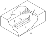
도 1은 예시적인 열적-제어가능 어레이를 포함하는 성형 표면을 갖는 몰드 공동 내부로 부분 절개하여 도시한 사시도이다.
도 2는 예시적인 온도-제어가능 어레이 및 이와 관련된 구성요소들의 전방측 사시도이다.
도 3은 부분 단면으로 표시된 몰드 공동의 일부를 또한 포함하는, 도 2의 예시적인 장치의 단부도이다.
도 4는 도 2의 예시적인 장치의 배면도이다.
도 5는 도 2의 예시적인 장치의 온도-제어가능 어레이의 온도-제어가능 요소의 분리된 상태의 전방측 사시도이다.
도 6은 도 2의 예시적인 장치의 예시적인 지지 부재의 분리된 상태의 측방 사시도이다.
도 7은 온도-제어가능 어레이 및 온도-제어가능 어레이의 작동을 위한 관련 구성요소의 개략도이다.
도 8은 온도-제어가능 어레이 및 이와 관련된 구성요소를 포함하는 다른 예시적인 장치의 전방측 사시도이다.
도 9는 도 8의 예시적인 장치의 후방측 사시도이다.
도 10은 예시적인 열적-제어가능 어레이를 포함하는 성형 표면을 갖는 몰드 공동 내부로 부분 절개하여 도시한 사시도이다.
다양한 도면의 유사한 도면 번호는 유사한 요소를 나타낸다. 일부 요소는 동일하거나 동등한 다수로 존재할 수 있으며; 이러한 경우에 오직 하나 이상의 대표적인 요소가 도면 번호에 의해 지칭될 수 있으나 그러한 도면 번호는 그러한 동일한 요소 모두에 적용됨이 이해될 것이다. 달리 지시되지 않는 한, 본 문서 내의 모든 도면은 축척대로 그려진 것이 아니며 본 발명의 상이한 실시예들을 예시하는 목적을 위해 선택된다. 특히, 다양한 구성요소들의 치수는 단지 설명적인 관점에서 도시되며, 다양한 구성요소들의 치수들 사이의 관계는 이렇게 지시되지 않는 한 도면으로부터 추론되어서는 안 된다. "상단", "하단", "상부", "하부", "아래", "위", "전방", "후방", "외향", "내향", "상방" 및 "하방", 그리고 "제1" 및 "제2"와 같은 용어들이 본 개시 내용에 사용될 수 있지만, 이들 용어는 달리 언급되지 않는다면, 도시된 특정 도면을 참조하여 설명을 용이하게 하기 위하여, 그들의 상대적 의미로만 사용됨을 이해하여야 한다. 본 명세서에 사용되는 바와 같이, 전방, 전방의, 전방으로, 전방을 대면하는, 최전방, 앞의, 앞으로, 가장 앞으로, 앞을 대면하는, 등과 같은 용어는 제1 및 제2 몰드 구성요소들이 합쳐졌을 때 형성되는 몰드 공동을 향하는 방향을 나타낸다. 후방, 후방의, 후방으로, 최후방, 후방을 대면하는, 등과 같은 용어는 그러한 몰드 공동으로부터 멀어지는 방향을 나타낸다.
특성 또는 속성에 대한 수식어로서 본 명세서에 사용되는 바와 같이, 용어 "대체로"는 달리 구체적으로 정의되지 않는 한, 특성 또는 속성이 절대적인 정밀도 또는 완벽한 일치를 요구함이 없이(예컨대, 정량화가능 특성에 대해 +/- 20% 이내) 당업자에 의해 용이하게 인식가능할 것이라는 것을 의미하며, 용어 "실질적으로"는 역시 절대적인 정밀도 또는 완벽한 일치를 요구함이 없이 높은 근사도(degree of approximation)(예컨대, 정량화가능 특성에 대해 +/- 10% 이내)를 의미한다. 정량화가능 특성 또는 속성에 적용되는 바와 같이, 엄격하게 동일한, 동등한, 균일한, 일정한 등과 같은 용어는 본 명세서에서 달리 정의되지 않는 한, +/- 5% 이내임을 의미한다.BRIEF DESCRIPTION OF THE DRAWINGS Figure 1 is a perspective view partially cut away into a mold cavity having a molding surface comprising an exemplary thermally-controllable array.
2 is a front perspective view of an exemplary temperature-controllable array and associated components.
Figure 3 is an end view of the exemplary device of Figure 2, also including a portion of the mold cavity shown in partial cross-section;
Figure 4 is a rear view of the exemplary device of Figure 2;
Figure 5 is a front side perspective view of the discrete state of the temperature-controllable element of the temperature-controllable array of the exemplary apparatus of Figure 2;
FIG. 6 is a side perspective view of an exemplary support member of the exemplary apparatus of FIG. 2 in an exploded state.
7 is a schematic diagram of associated components for operation of a temperature-controllable array and a temperature-controllable array.
Figure 8 is a front side perspective view of another exemplary device comprising a temperature-controllable array and associated components.
Figure 9 is a rear side perspective view of the exemplary device of Figure 8;
Figure 10 is a perspective view partially cut away into a mold cavity having a molding surface comprising an exemplary thermally-controllable array.
Like numbers in the various drawings indicate like elements. Some elements may be present in the same or an equivalent plurality; It will be understood that in such a case, only one or more representative elements may be referred to by the number of the drawings, but such numbers apply to all such identical elements. Unless otherwise indicated, all drawings in this document are not drawn to scale and are selected for purposes of illustrating different embodiments of the present invention. In particular, the dimensions of the various components are shown in an illustrative view only, and the relationship between the dimensions of the various components should not be deduced from the figures unless indicated otherwise. The terms "top,""bottom,""top,""bottom,""bottom,""top,""front,""rear,""outward,"" The terms " first "and" second "may be used in the present disclosure, they should be understood to be used only in their relative sense, unless otherwise stated, do. As used herein, terms such as forward, forward, forward, frontward, forward, forward, forward, forward, forward, and the like refer to the combination of first and second mold components And the direction toward the mold cavity formed at the time of disconnection. Rearward, rearward, rearward, rearward, rearward, and the like, refer to directions away from such mold cavity.
As used herein as a modifier for a characteristic or attribute, the term "generally ", unless the characteristic or attribute requires absolute precision or perfect agreement (e.g., for a quantifiable characteristic, / - 20%), and that the term "substantially" also refers to a high degree of approximation (e.g., for a quantifiable characteristic) without requiring absolute precision or perfect agreement Within +/- 10%). Unless otherwise defined herein, terms such as strictly equivalent, equivalent, uniform, constant, etc., as applied to quantifiable characteristics or attributes, are meant to be within +/- 5%.
사출 성형 공동의 성형 표면 내에서 열에너지의 시간적인 그리고 공간적인 제어를 위한 장치 및 방법이 본 명세서에 개시되어 있다. 예시적인 몰드 공동(8)이 도 1에 총칭적인 표현으로 도시되어 있다. 당업자는 예컨대 적어도 제1 성형 표면(4)을 포함하는 제1 몰드 구성요소(5) 및 적어도 제2 성형 표면(6)을 포함하는 제2 몰드 구성요소(7)를 합침으로써 몰드 공동(8)이 제공될 수 있다는 것을 인식할 것이다. (도 1이 특징부들, 예컨대 제1 몰드 구성요소와 제2 몰드 구성요소 사이의 분리선, 탕구, 게이트, 러너(runner), 압출 봉(ejector pin) 등이 명확성을 위하여 생략된 몰드 공동의 단순화된 표현이라는 것이 강조된다.) 본 명세서에 개시된 바와 같이, 몰드 공동 스킨(3)의 전방 표면(4)은 몰드 공동(8)의 적어도 일부를 한정한다. 적어도 하나의 열적-제어가능 어레이(1)는 표면(4)의 일부 영역 위에 구비된다. 용어 열적-제어가능 어레이는 온도가 개별적으로 그리고 별도로 조작가능한 표면(4)의 임의의 복수개의 (즉, 적어도 2개 이상의) 구역(2)을 망라하도록 본 명세서에서 폭 넓게 사용된다(본 명세서의 여기 및 다른 부분에서 용어 "어레이"를 사용하는 것은 어레이의 구역들이 반드시 규칙적이거나 균일하거나 대칭적인 패턴으로 배열되어야 한다는 것을 시사하는 것은 아니라는 것에 유의한다). 어레이(1)는 본 명세서에서 편의상 어레이(1)의 개별 구역(2)의 온도가 반드시 직접 모니터링될 수 있어야 하는 것은 아니어도 된다(그러나 이는 요구되는 경우 모니터링될 수 있음)는 사실을 고려하여 온도-제어가능 어레이보다는 오히려 열적-제어가능 어레이라 칭해진다. 이러한 명명법은 개별 요소의 온도가 직접 모니터링 및 제어될 수 있는 아래에서 설명되는 온도-제어가능 어레이로부터 열적-제어가능 어레이(1)를 구별할 것이다.An apparatus and method for temporal and spatial control of thermal energy within a molding surface of an injection molding cavity are disclosed herein. An
설명의 편의성을 위해, 어레이(1)의 개별 구역(2)은 본 명세서에는 픽셀이라 칭해질 수 있다. 어레이(1)의 픽셀(2)들은 표면(4)의 구역들로서, 이 구역들은 임의의 물리적 경계 또는 그들 사이의 분리 특징부를 반드시 가져야 하거나 시각적으로 서로 구별가능하여야 하는 것은 아니어도 되고 대부분의 경우 그렇지 않을 것이라는 것을 이해할 것이다. 오히려, 픽셀(2)들은 단지, 본 명세서에서 하기에 논의되는 바와 같이 온도-제어가능 어레이의 온도-제어가능 요소에 열적으로 결합되어 개별적으로 열적으로 제어될 수 있는 (예컨대, 서로 상이한 온도들로 안정적으로 유지될 수 있는) 스킨(3)의 표면(4)의 구역들이다. 픽셀(2)은 요구되는 바와 같이 임의의 적합한 개수, 크기, 형상 및 간격으로 존재할 수 있다(그리고 배열은 본 명세서에서 더 상세히 설명되는 바와 같이 온도-제어가능 어레이의 온도-제어가능 요소들의 원하는 개수, 크기, 형상 및 간격을 사용함으로써 달성될 수 있다).For convenience of description, the
앞서 논의된 바와 같이, 어레이(1)는 몰드 공동 스킨(3)의 전방 표면(4) 내에 마련된다. 일부 실시예에서, 공동 스킨(3)은 스킨(3)의 두께가, 어레이(1)의 픽셀(2)의 측방향 범위에 걸친 평균으로, 약 5 mm 이하인 것을 의미하는 얇은 스킨일 수 있다. 추가 실시예에서, 스킨(3)의 두께는 약 2, 1, 0.5 또는 0.3 mm 미만일 수 있다. 일부 실시예에서, 공동 스킨(3)은 스킨(3)의 재료가, 어레이(1)의 임의의 특정 픽셀(2)에서, 약 100 W/m-℃ 미만의 열전도율을 포함하는 것을 의미하는 낮은 열전도율 스킨일 수 있다. 다양한 실시예에서, 스킨(3)의 재료는 열전도율이 약 80, 60, 또는 40 W/m-℃ 미만일 수 있다. 추가 실시예에서, 스킨(3)의 재료는 열전도율이 약 5, 10, 20, 또는 25 W/m-℃ 초과일 수 있다. 일부 실시예에서, 스킨(3)의 재료는 스킨이 위에 놓이고 열적으로 결합된 온도-제어가능 요소의 본체의 재료의 열전도율의 80%, 60%, 40%, 또는 20% 미만인 열전도율을 포함할 수 있다.As discussed above, the
폭 넓게 요약하자면, 어레이(1) 및 그의 개별 픽셀(2)은 개별 온도-제어가능 요소들을 포함하는 온도-제어가능 어레이를 통해서 열적으로 제어될 수 있고, 예컨대 상이하게 열적으로 제어될 수 있고, 이들 요소의 각각은 각각의 개별 픽셀(2)이 그가 열적으로 결합되는 온도-제어가능 요소의 온도를 변화시킴으로써 열적으로 제어될 수 있도록 열적-제어가능 어레이(1)의 상이한 개별 픽셀(2)에 열적으로 결합될 수 있다. 실제로, 이는 온도-제어가능 어레이의 요소 각각의 전방 표면이 원하는 구역 (따라서 그 구역 내의 스킨(3)의 전방 표면(4)이 어레이(1)의 픽셀(2)이 됨) 내의 몰드 공동 스킨(3)의 후방 표면에 열적으로 결합되도록 (예컨대, 그와 긴밀하게 접촉하도록) 온도-제어가능 어레이를 제공함으로써 달성될 수 있다. 임의의 온도-제어가능 어레이가 그러한 목적을 위해 사용될 수 있는 한편, 특히 적합할 수 있는 예시적인 온도-제어가능 어레이는 도 2 내지 도 4, 도 8 및 도 9에 도시되어 있고 이후 본 명세서에서 더 상세히 논의될 것이다.To summarize, the
온도-제어가능 어레이의 개별 온도-제어가능 요소들은 본 명세서에서 상세히 논의되는 바와 같이, 서로로부터 측방향으로 단열될 수 있다. 그러나, 이는 공동 스킨(3)에 의해 제공되는 이웃 픽셀들 사이의 열에너지의 전도를 위한 측방향 경로의 존재를 반드시 배제하지는 않는다. 오히려 (예컨대, 충분히 얇은 그리고/또는 낮은 열전도율 재료로 제조된 스킨(3)을 통하여), 일부 실시예에서는, 스킨(3)의 두께 치수를 통한 (즉, (온도-제어가능 요소의 전방면과 접촉하는) 스킨의 후방 표면으로부터 (몰드 공동(8)의 성형 표면을 제공하는) 스킨의 전방 표면으로 이어지는 스킨의 최단 치수를 통한) 열에너지의 전도가, 스킨을 따르는 (즉, 하나의 픽셀(2)로부터 인접한 픽셀(2)로의) 열에너지의 측방향 전도와 비교하여 스킨을 통한 열에너지의 전달을 위한 주요한 경로로 제공될 수 있다. 이는, 가장 인접한 이웃 픽셀이 열적으로 제어될 수 있는 조건과 대체적으로 관계없이, 임의의 특정 픽셀(2)이 그 픽셀(2)의 스킨(3)의 후방 표면에 열적으로 결합된 온도-제어 요소를 통하여 충분히 열적으로 제어될 수 있음을 제공할 수 있다. 예를 들어, 제1 픽셀이 특정 온도 또는 온도 범위로 유지되는 경우, 그럼에도 불구하고 인접한 픽셀은, 인접한 픽셀을 원하는 온도 범위로 충분히 유지하지 못하게 할 정도의 열에너지의 초과분을 제1 픽셀로 잃어버리지 않거나 또는 그 정도의 열에너지의 초과분을 제1 픽셀로부터 수용하지 않고서, 제1 픽셀의 온도보다 유의하게 더 높거나 더 낮은 (그에 열적으로 결합된 온도-제어가능 요소에 의해 조정된) 온도 또는 온도 범위로 유지될 수 있다.The individual temperature-controllable elements of the temperature-controllable array can be insulated laterally from each other, as discussed in detail herein. However, this does not necessarily preclude the existence of a lateral path for the conduction of thermal energy between neighboring pixels provided by the
상기 원리는 열적-제어가능 어레이(1)의 픽셀(2)에 대한 종횡비에 관하여 특징지어질 수 있다. 그러한 종횡비는 2개의 파라미터로 한정될 수 있다. 제1 파라미터는 스킨의 두께 치수를 따른 픽셀(2) 내의 공동 스킨(3)의 두께 "t"이다(예시적인 거리 "t"가 도 3에 도시되어 있다). 제2 파라미터는 픽셀(2)의 중심점과 가장 인접한 이웃 픽셀(2)의 가장 가까운 중심점 사이의 중심에서 중심까지의 거리 "l"이다. 예시적인 거리 "l"이 도 1에 도시되어 있다. (앞서 논의된 바와 같이, 어레이(1)의 픽셀(2)의 형상, 크기, 및 중심점이 공동 스킨(3)에 열적으로 결합된 온도-제어가능 요소의 전방 표면(예컨대, 도 2 및 도 3의 표면(61))의 형상, 크기 및 중심점에 의해 주로 좌우될 수 있다는 것을 이해할 것이다.) 만일 픽셀(2)이 불규칙하거나 비대칭인 형상을 포함하는 경우, 픽셀(2)의 도심(centroid)(기하학적 중심)이 이러한 목적을 위해 중심점으로서 이용될 수 있다. 그러므로, 이들 파라미터에 의해, 픽셀 종횡비는 l/t 비로서 계산될 수 있다. 다양한 실시예에서, 열적-제어가능 어레이(1)의 픽셀(2)은 적어도 약 2:1, 4:1, 8:1, 또는 16:1인 종횡비를 포함할 수 있다.The principle can be characterized with respect to the aspect ratio for the
따라서, 요약하자면, 전술된 배열은 인접한 픽셀(2)이 개별적으로, 예컨대 구별적으로 열적으로 제어되는 것이 (예를 들어, 예컨대 섭씨 5, 10, 또는 20도 이상씩 서로 상이할 수 있는 온도가 되는 것이 그리고/또는 그 온도로 유지되는 것이) 가능하게 한다. 따라서, 유의한 열적 구배가 유리하게는 (예컨대, 어레이(1) 내에서, 그리고/또는 성형 표면(4)의 다른 어레이 외(non-array) 영역과 어레이(1) 사이에서) 공동(8)의 성형 표면(4)의 선택된 영역에 걸쳐 수립 및/또는 유지될 수 있다. 비록 그러한 구별적인 열적 제어가 가능할 수 있더라도, 몇몇 경우에, 어레이의 2개 이상의 픽셀이 유사한 또는 동일한 온도 범위로 제어될 수 있다는 것을 이해할 것이다. 앞서 논의된 바와 같이, (예컨대 하나의 픽셀로부터 이웃 픽셀까지) 몰드 공동 스킨(3)을 따른 열에너지의 일부 측방향 전도가 일어날 수 있다는 것이 추가로 이해될 것이다. 그러나, 몰드 공동 스킨을 따르는 일부 열전도 양은 원하는 열 구배가 유지될 수 있는 한 불리하지 않을 수 있다. 실제로, 인접한 픽셀들 사이에서 몰드 공동 스킨을 따르는 일부 열전도 양에 의해 유리하게는 인접한 픽셀(2)들 사이의 온도 변화가 예컨대 인접한 픽셀(2)들과 접촉하는 유동가능한 (예컨대, 용융된) 수지 내에 불리하게 가파른 열 구배를 야기할 정도로 급격하지 않게 될 수 있다.Thus, in summary, the above-described arrangement requires that
따라서, 임의의 2개의 픽셀의 이웃하는 에지에 대해, 예컨대 온도의 수직에 가까운 단차 변화가 2개의 픽셀들 사이의 정확히 경계에 존재하는 것보다는 오히려, 온도 구배가 픽셀의 이웃하는 에지에 근접한 픽셀 각각의 경계 구역에 존재할 수 있다는 것을 이해할 것이다. 픽셀의 에지에 근접하지 않은 픽셀의 심지어 측방향 내부 구역 내의 온도 프로파일이 반드시 완전히 평탄하지 않을 수 있다는 것이 또한 이해될 것이다. 즉, 몇몇 상황에서, 그러한 측방향 구역 내의 온도는 (예컨대, 섭씨 5, 2, 1, 또는 0.5도 이하의) 변동을 보일 수 있다. 픽셀의 심지어 그러한 측방향 내부 구역의 온도가 몇몇 상황에서 일시적으로 변동될 수 있다는 것이 또한 이해될 것이다. 그러한 상황은 예컨대 픽셀이 고온으로 용융된 수지와 접촉되는 경우에 일어날 수 있다.Thus, for a neighboring edge of any two pixels, for example, a temperature gradient that is close to the vertical, rather than a precise boundary between two pixels, Lt; RTI ID = 0.0 > of the < / RTI > It will also be appreciated that the temperature profile within even the lateral internal region of the pixel that is not close to the edge of the pixel may not be completely flat. That is, in some situations, the temperature in such a lateral zone may exhibit a variation (e.g., 5, 2, 1, or even 0.5 degrees Celsius). It will also be appreciated that the temperature of even such a lateral internal region of the pixel can be temporarily varied in some situations. Such a situation can occur, for example, when a pixel is contacted with a molten resin at a high temperature.
당업자는 (예컨대, 특정 구역 내의 공동 스킨에 열적으로 결합되어 그 위에 픽셀을 제공하는 온도-제어가능 요소에 의해 수립된 공칭 설정값으로부터 떨어져 있는) 온도에서의 이들의 임의의 편차가 발생할 수 있는 크기는, 예를 들어 다양한 요인들, 예컨대 픽셀 크기 및 다른 픽셀에 대한 근접도, 픽셀이 제어될 수 있는 공칭 온도, 전술된 픽셀의 종횡비, 픽셀과 접촉하게 되는 성형 수지의 온도, 등에 좌우될 수 있다는 것을 이해할 것이다. 그러나, 예컨대 임의의 그러한 작은 그리고/또는 순간적인 변동을 제외하고, 그리고 픽셀의 측방향 에지에서의 또는 그 근처에서의 임의의 편차에도 불구하고, 다양한 실시예에서, 어레이(1)의 픽셀(2)의 측방향 내부 구역의 온도는 (예컨대, 섭씨 플러스 또는 마이너스 5도, 섭씨 플러스 또는 마이너스 2도, 또는 심지어 섭씨 플러스 또는 마이너스 1도 이내로) 정밀하게 제어될 수 있다는 것을 이해할 것이다. 이는 픽셀의 온도가 실제로 직접 모니터링되는지 아닌지의 문제일 수 있다.Those skilled in the art will appreciate that any variation in temperature (e.g., away from the nominal set point established by the temperature-controllable element thermally coupled to the co-skins within a particular zone to provide pixels thereon) May depend, for example, on various factors such as the pixel size and proximity to other pixels, the nominal temperature at which the pixel can be controlled, the aspect ratio of the pixels described above, the temperature of the molding resin coming into contact with the pixel, I will understand. However, notwithstanding any such small and / or instantaneous variations, and in spite of any deviations at or near the lateral edges of the pixels, in various embodiments, the
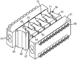
도 2 내지 도 4의 예시적인 실시예에서는 열적-제어가능 어레이(1)를 제공하도록 공동 스킨에 열적으로 결합될 수 있는 예시적인 온도-제어가능 어레이(50)가 도시되어 있다. 어레이(50)는 그러한 온도-제어가능 어레이의 단지 하나의 대표적인 유형이지만, 이는 그러한 어레이의 일반적인 개념 및 원리를 논의하기 위하여 이용될 것이다. 예시적인 온도-제어가능 어레이(50)는 개별 온도-제어가능 요소(60)들로 구성된다. 도 2 및 특히 도 3에 도시된 바와 같이, 어레이(50)의 각각의 개별 요소(60)는 공동 스킨(3)의 후방 표면과 긴밀한 열적 접촉 상태로 배치되도록 구성된 전방 표면(61)을 갖는 본체(70)를 포함할 수 있다. 일부 실시예에서, 본체(70)는 높은 열전도율(예컨대, 약 80 W/m-℃ 초과)을 가질 수 있고, 추가 실시예에서, 적어도 약 100, 150, 200, 또는 250 W/m-℃인 열전도율을 포함할 수 있다. 일부 실시예에서, 요소(60)의 본체(70)는 금속으로 제조될 수 있다. 특정 실시예에서, 이는 구리 또는 구리 합금을 포함하는 성분으로 제조될 수 있다. 일부 실시예에서, 그러한 구리 합금은 베릴륨-구리 합금일 수 있다. 다른 실시예에서, 그러한 구리 합금은 미국 위스콘신주 저먼타운 소재의 퍼포먼스 알로이스(Performance Alloys)로부터 상표명 몰드스타(MOLDSTAR)로 입수가능한 재료에 의해 예시되는 바와 같은, 열전도율이 높은 무베릴륨 구리 합금일 수 있다.2 through 4, an exemplary temperature-
도 2의 예시적인 실시예에서, 전방 표면(61)은 요소(60)의 본체(70)의 일부분(62) 상에 구비되고, 이 일부분(62)은 하중 지지 부재로서 역할을 할 수 있다. 즉, 부재(62)는, 온도-제어가능 어레이(50)와 함께 사용되는 제1 몰드 구성요소(5)가 사출 성형 작업에 이용되는 사출 압력에 상응하는 힘으로 제2 몰드 구성요소와 함께 합쳐지는 경우, 몰드 구성요소(예컨대, 도 1의 구성요소(5))를 통한 하중 지지 경로의 적어도 일부를 제공할 수 있다.In the exemplary embodiment of FIG. 2, the
각각의 본체(70)는 또한, 하중 지지 부재(62)에 측방향으로 인접한 (그리고 그에 일체로 연결된) 그리고 공동 스킨(3)과 긴밀한 접촉 상태에 있는 표면을 반드시 갖지 않을 수 있는 열교환 모듈(63)을 포함할 수 있다. 이러한 상황에서, 측방향으로는 스킨(3)의 두께(최단 치수)를 통한 열에너지 전도의 방향에 적어도 대체로 직교하는 것을 의미한다(상기 방향은 또한 전형적으로 부재(62)를 통한 하중 지지 경로에 적어도 대체로 직교할 수 있다). 아래에서 상세히 논의되는 바와 같이, 도 2 내지 도 4의 예시적인 배열에서, 열에너지는 외부 공급원으로부터 열교환 모듈(63) 내로 전달될 수 있고 그리고/또는 그로부터 제거될 수 있고, 열교환 모듈(63)로부터 하중 지지 부재(62) 내로 측방향으로 전도될 수 있어서 본체(70)의 전체(즉, 모듈(63) 및 부재(62) 둘 모두)가 원하는 온도에 있도록 할 수 있다. 이는 부재(62)의 전방 표면(61)이 이러한 원하는 온도에 있도록 할 것이고, 따라서, 원하는 바와 같이, 열에너지가 그로부터 스킨(3)으로 전달되게 하거나 또는 스킨(3)으로부터 제거되게 할 것이다.Each
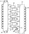
온도-제어가능은 온도-제어가능 어레이의 개별 요소의 온도가 (예컨대, 연속적으로든, 또는 원하는 제어를 달성하기에 적합한 빈도로 간헐적으로든 간에) 모니터링될 수 있고 제어기에 의해 이러한 모니터링된 온도를 이용하여 열에너지의 전달이 요소로 또는 그로부터 지향하게 하여 요소의 온도를 변화시킬 수 있어서, 예컨대 이 온도가 원하는 설정값에 있도록 할 수 있어서, 즉 요소가 폐루프 온도 제어를 거치게 한다는 것을 의미한다. 그러한 온도 모니터링은, 예컨대 온도 감지 디바이스를 이용함으로써 달성될 수 있다. 그러한 목적을 위해 소위 저항 온도 검출기(resistance temperature detector, RTD)를 사용하는 것이 편리할 수 있지만, 임의의 적합한 온도-감지 디바이스가 사용될 수도 있다. 그러한 온도 감지 디바이스는 요소의 전방측(즉, 요소가 열적으로 결합된 공동 스킨에 가장 가까운 측)에 근접하게 위치되는 것이 유리할 수 있다. 따라서, 도 2의 예시적인 실시예에서, 각각의 요소(60)에는 그러한 요소(60)의 온도가 개별적으로 모니터링될 수 있도록 하는 (예컨대, 도 3의 온도 감지 디바이스(13)에 의해 표현되는 바와 같이) 온도 감지 디바이스를 수용할 수 있는 공동(64)이 구비된다. 도 2의 예시된 실시예에서, 온도 감지 디바이스가 배선(예컨대, 도 3의 배선(52))에 연결될 수 있도록 액세스 윈도우(access window)(65)가 구비된다. 그러나, 그러한 온도 감지 디바이스와의 통신(예컨대, 광섬유, 무선, 등)의 임의의 적합한 방법이 이용될 수 있다.The temperature-controllable can be monitored by monitoring the temperature of the individual elements of the temperature-controllable array (e. G. Continuously or intermittently with frequency appropriate to achieve the desired control) and using this monitored temperature by the controller The transfer of thermal energy can be directed to or from the element to change the temperature of the element, for example, to make it at the desired set point, i. E., To cause the element to undergo closed loop temperature control. Such temperature monitoring can be achieved, for example, by using a temperature sensing device. While it may be convenient to use a so-called resistance temperature detector (RTD) for that purpose, any suitable temperature-sensing device may be used. It may be advantageous that such a temperature sensing device is located proximate the front side of the element (i.e., the side closest to the thermally coupled cavity skin). Thus, in the exemplary embodiment of FIG. 2, each
각각의 요소(60)는 적어도 제1 열전달 메커니즘에 의해 가열 및/또는 냉각될 수 있다. 일부 실시예에서, 그러한 제1 열전달 메커니즘은, 어레이(50) 또는 몰드 구성요소(5)의 외부에 있는 가열 또는 냉각 유닛에 의해 가열 또는 냉각되는 이동형 열전달 유체를 수반하지 않는 것을 의미하는 정적 메커니즘을 포함할 수 있다. (그와 같이, 일부 실시예에서, 그러한 제1 열전달 메커니즘은, 폐쇄 단부를 갖는 비-이동식 용기 내에 전체적으로 포함되고 그 내에서 전체적으로 내부 재순환되는 가열 또는 냉각 유체를 포함하는 소위 히트 파이프를 포함한다. 그러나, 다른 실시예에서, 어레이 내에 또는 그와 함께 몰드 구성요소 내에 히트 파이프가 존재하지 않는다.) 일부 실시예에서, 그러한 제1 정적 열전달 메커니즘은 전기적 가열/냉각 요소(예컨대, 둘 모두가 도 4에 총칭적인 표현으로 도시된 배선(55)에 의해 전력공급되는 바와 같은 요소(14))를 통한 전기적 가열 또는 냉각을 포함할 수 있다. 그러한 요소는 요소(60)의 본체(70)에 열적으로 결합될 수 있는데; 예컨대, 이는 도 4의 배면도에 도시된 바와 같이 요소(60)의 본체(70)와 긴밀하게 접촉하고 있는 요소(14)와 함께 요소(60)의 후방으로 개방된 단부를 갖는 공동(69) 내로 삽입될 수 있다. (도 4의 특정 설계에서, 가열/냉각 요소(14)는 열교환 모듈(63)에 열적으로 결합되어 그 내부로 전달된 열에너지가 하중 지지 부재(62) 내로 측방향으로 전도될 수 있게 한다). 가열 또는 냉각이 가능한 전기 디바이스(예컨대, 펠티에(Peltier) 디바이스)가 사용될 수 있지만, 많은 경우에, 가열만을 위한 제1 전기 열전달 메커니즘을 사용하는 것이 편리할 수 있다. 그러한 실시예에서, 전기적으로 구동되는 정적 요소(14)는 히터(예컨대, 통상 알려진 바와 같은 전기 저항 히터)일 수 있다. 그러나, 임의의 적합한 유형의 가열 또는 냉각 요소는, 적절한 열적 결합이 제공되는 한, 임의의 적합한 체결 메커니즘에 의해 임의의 적합한 방식으로 요소(60)와 접촉될 수 있고 그에 대해 유지될 수 있다. 예를 들어, 그러한 요소는 외부 압력에 의해 제 위치에 유지될 수 있거나, 또는 전도성 접착제, 땜납 등이 이를 본체(70)에 부착하기 위하여 사용될 수 있다.Each
각각의 요소(60)는 또한, 일부 실시예에서, 제1 메커니즘과 상이할 수 있는 제2 열전달 메커니즘에 의해 가열 및/또는 냉각될 수 있다(제1 및 제2의 명칭이 임의적이라는 것은 당연히 이해될 것이다). 다른 열전달 메커니즘과는 상이한 열전달 메커니즘은 상이한 물리적 원리에 의해 작동하는 메커니즘들, 예를 들어 본 명세서에서 설명되는 바와 같은 동적 메커니즘 대 정적 메커니즘을 포함한다. 그러나, 다른 열전달 메커니즘과는 상이한 열전달 메커니즘은, 양 메커니즘들이 동일한 원리에 의해 작동될 수 있는 (예컨대, 양자 모두가 이동형 열전달 유체를 통한 동적 열전달을 포함할 수 있거나, 또는 양자 모두가 펠티에 디바이스에 의한 예컨대 가열 또는 냉각을 포함할 수 있는) 경우와 그와 달리 메커니즘들이 서로에 대해 대비되게 (즉, 하나의 메커니즘의 효과가 다른 메커니즘의 효과를 적어도 부분적으로 상쇄할 수 있도록) 동일한 온도-제어가능 요소에 적어도 대체로 동시에 적용될 수 있는 경우를 또한 포함한다. 따라서, 일반적인 의미에서, 동일한 온도-제어가능 요소는 열 방출원에 그리고 또한 열 흡수원에 열적으로 결합될 수 있는데, 이들은 실질적으로 동시에 또는 동시에 열에너지를 요소에 부가하고 열에너지를 요소로부터 제거하도록 각각 작동할 수 있다. 특정 예는 온도-제어가능 요소가 제1 열전달 유체에 의해 가열되고, 예컨대 동시에, 제1 열전달 유체와 관계없이 제어되는 제2 열전달 유체에 의해 냉각되는 것일 수 있다. 통상, 임의의 특정 시간에, 요소(60)가 제1 메커니즘에 의해 단독으로, 제2 메커니즘에 의해 단독으로, 둘 모두의 사용에 의해 조합하여 가열 또는 냉각될 수 있거나, 또는 어느 하나의 메커니즘에 의해 가열 또는 냉각되지 않을 수 있는데, 이는 이후 본 명세서에서 상세히 논의되는 바와 같다.Each
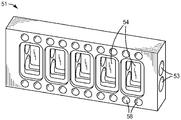
도 2 내지 도 6에서 예시되는 바와 같이, 일부 실시예에서, 그러한 제2 열전달 메커니즘은 열에너지를 요소(60)의 본체(70)로 전달하거나 또는 열에너지를 그로부터 제거하는 이동형 열전달 유체(그의 온도는 어레이(50) 및 몰드 구성요소(5)의 외부에 존재하는 제어 유닛에 의해 제어됨)에 의해 달성되는 동적 열전달 메커니즘일 수 있다. 그러한 동적 열전달 능력은 요소(60)의 본체(70)가 기체(예컨대, 공기, 질소, 증기 등) 또는 액체(예컨대, 물, 오일, 등)일 수 있는 그러한 이동형 열전달 유체로 열너지를 직접적으로 또는 간접적으로 전달하거나 그로부터 열너지를 직접적으로 또는 간접적으로 수용할 수 있는 적어도 하나의 동적 열전달 구조물을 포함하는 것을 제공함으로써 달성될 수 있다. 도 2 내지 도 6의 특정 실시예에서, 그러한 동적 열전달 구조물은 하나 이상의 동적 열전달 핀(heat-transfer fin)(66)의 형태를 취할 수 있으며, 이는 도 3 및 도 5에 가장 명확하게 도시된 바와 같다. 용어 동적 열전달 핀은, 본 명세서에서, 요소(60)의 본체(70)로부터 돌출된 (예컨대 그의 일체로 돌출된 부분인) 그리고 핀의 높이(돌출 거리) 대 핀의 두께(그의 최단 축을 따라 핀을 가로지른 평균 거리를 위미하는 것으로, 최단 거리는 핀의 높이 축에 그리고 유체 유동 방향에 대체로 직교하는 축을 종종 따라서 있을 것임)의 종횡비가 높은(열전달 핀의 특정 경우에는 적어도 2:1임을 의미함) 임의의 구조물을 의미하는 것으로서 넓게 정의된다. 다양한 실시예에서, 그러한 핀의 종횡비는 적어도 3:1 또는 5:1일 수 있다. 핀은 임의의 적합한 형상 및 크기를 가질 수 있고, 임의의 적합한 개수로 존재할 수 있다.As illustrated in Figures 2 to 6, in some embodiments, such a second heat transfer mechanism is a transfer heat transfer fluid (the temperature of which is transferred to the array < RTI ID = 0.0 > Controlled by a control unit present on the outside of the
도 2 내지 도 6의 예시적인 실시예에서, 온도-제어가능 어레이(50)는 하나 이상의 지지 블록(51)에 의해 지지될 수 있다. 예시적인 설계에서, 제1 지지 블록(51)은 요소(60)의 제1 세트의 본체(70)에 (예컨대, 그의 열교환 모듈(63)의 측방향-외향 부분에) 부착될 수 있다. 그러한 부착은 (도 6에 도시된 바와 같이) 지지 블록(51) 내의 볼트 구멍(58)을 통과할 수 있고 이어서 (예컨대 도 5에 도시된 바와 같이) 각각의 요소(60)의 본체(70) 내의 볼트 구멍(68) 내로 들어갈 수 있는 볼트(59)를 통해 이루어질 수 있어서, 도 2 내지 도 4에 도시된 바와 같이 본체(70)를 지지 블록(51)에 부착할 수 있다. 유사한 제2 지지 블록(51)이 요소(60)들의 대면하는 제2 세트의 본체들에 부착될 수 있는데, 이는 다시 도 2 내지 도 4에 도시된 바와 같다. 이어서, 지지 블록(51)은 예컨대 플래튼에 의해 지지되는 몰드 베이스에 부착될 수 있는데, 이는 당업자에 의해 잘 이해되는 바와 같다(종종 몰드 구성요소(5)는 동일한 몰드 베이스에 부착될 수 있다). 어레이(50)의 요소(60)를 지지 및 안정화하는 것에 더하여, 도 2 내지 도 6에 도시된 바와 같은 지지 블록이 이동형 열전달 유체를 열에너지를 요소(60)의 본체(70)와 교환하도록 하는 위치로 가져오는 기능을 또한 제공할 수 있다. 따라서, 도 6에 도시된 지지 블록(51)의 분리된 도면에서 가장 용이하게 도시된 바와 같이, 지지 블록(51)은, 지지 블록(51)의 내부를 통하여 연장되고 이동 유체가 핀(66)과 접촉할 수 있도록 요소(60)의 본체(70)의 열전달 구조물(예컨대, 핀)(66)이 존재할 수 있는 공간(54) 내로 그리고 그를 통하도록 이동형 열전달 유체를 지향시키는 하나 이상의 (예시된 실시예에서, 2개의) 유체 유동 채널(53)을 포함할 수 있다. (그러한 유체 유동 채널은 유체-공급 도관(56) 및 유체 배출 도관(57)에 연결될 수 있으며, 이들 둘 모두는 도 4에 총칭적인 표현으로 도시된 바와 같다.) 그러한 설계는 어레이(50)의 모든 요소(60)의 동적 열전달 구조물(예컨대, 핀)의 모두가 공통 열전달 유체에 노출되는 것이 바람직한 경우에 특히 적합할 수 있다는 것을 이해할 것이다. (공통 유체는, 유체가 요소(60)의 연속적인 열전달 구조물을 지나서 진행함에 따라 유체의 온도의 일부 변화가 발생할 수 있음에도 불구하고, 예컨대 가열/냉각 유닛에 의해 설정값으로 제어되는 바와 같이 동일한 공칭 온도에 있는 유체를 의미한다). 일부 실시예에서, 지지 블록(들)(51)은 예컨대 열전도율이 80 W/m-℃ 미만인 낮은 열전도율 재료로 제조될 수 있다. 추가 실시예에서, 지지 블록(들)(51)은 약 60, 40 또는 30 W/m-℃ 미만인 열전도율을 포함할 수 있다. 더 추가의 실시예에서, 지지 블록(들)(51)은 단열 재료, 예컨대 열전도율이 약 25 W/m-℃ 미만인 단열 재료일 수 있다. 그러한 배열은 유리하게는 요소(60)들의 서로로부터의 아래에서 설명되는 측방향 단열을 향상시킬 수 있다.In the exemplary embodiment of Figures 2-6, the temperature-
온도-제어가능 어레이의 온도-제어가능 요소들 중 적어도 일부, 예컨대, 그의 본체가, 서로로부터 측방향으로 단열될 수 있다. 즉, 임의의 특정 요소가 적어도 그의 이웃 요소 또는 요소들로부터 측방향으로 단열될 수 있다. 그러한 측방향 단열은, 열에너지가 요소의 본체로부터 이웃 요소의 본체로 (즉 그 요소의 본체를 이웃 요소의 본체로부터 분리하는 개재된 거리(공간)를 가로질러) 전도되는 능력에 대한, 열에너지가 그 요소의 본체 내에서 전도되는 능력의 관점에서 고려될 수 있다. 달성될 그러한 측방향 단열에 대해, 후자의 능력이 전자의 능력에 비해 지배적이어야만 한다. 요소들의 서로로부터의 측방향 단열은 임의의 적합한 방식으로 제공될 수 있고, 단열의 다수 방법이 단일 요소를 위해 사용될 수 있다. 일반적으로, 그러한 방법은 인접한 요소들의 본체들의 표면들 사이의 개재 공간 내에 (특히, 서로 가장 가깝게 대면하는 인접한 요소들의 본체의 표면들 사이 내에) 비교적 낮은 열전도율을 갖는 재료 또는 재료들을 제공하는 것에 좌우될 수 있다. 따라서, 도 2에 도시된 실시예에서, 에어 갭이 인접한 요소(60)들의 열교환 모듈(63)들 사이에 마련된다. 공기의 열전도율은 0.1 W/m-℃ 미만이기 때문에, 이는 (예컨대, 에어 갭이 적어도 약 0.1 mm 이상이어서 인접한 본체들의 표면들 사이에 용인하기 어려울 정도의 높은 복사 열전달률의 가능성을 최소화하는 한) 효율적인 단열을 제공할 수 있다. 다양한 실시예에서, 그러한 에어 갭은 요소들(예컨대, 그의 본체들)의 서로에 대한 가장 가까운 접근 점에서 적어도 약 0.2, 0.5, 1.0, 또는 2.0 mm일 수 있다. 용어 에어 갭은 총칭적으로 사용될 수 있고 적합하게 낮은 열전도율의 임의의 기체 상태 유체(예컨대, 질소)나 또는 심지어 부분 진공이 그러한 갭 내에 존재할 수 있다는 것을 이해할 것이다. 일부 실시예에서, 인접한 요소들 사이의 갭의 적어도 일부는 비-기체 상태의 낮은 열전도율 유체(예컨대, 열전도율이 약 25 W/ m-℃ 미만인 단열 오일 또는 그리스)로 충전될 수 있다.At least some of the temperature-controllable elements of the temperature-controllable array, e.g., the body thereof, may be insulated laterally from each other. That is, any particular element may be insulated laterally from at least its neighboring elements or elements. Such lateral insulation is a function of the ability of thermal energy to be conducted from the body of the element to the body of the neighboring element (i.e., across an intervening distance (space) separating the body of the element from the body of the neighboring element) Can be considered in terms of the ability to be conducted in the body of the element. For such lateral insulation to be achieved, the latter capability must be dominant over the former. The lateral insulation from each other of the elements can be provided in any suitable manner, and multiple methods of insulation can be used for a single element. Generally, such a method will depend on providing materials or materials having a relatively low thermal conductivity within the interstitial space between the surfaces of the bodies of adjacent elements (especially between the surfaces of the body of adjacent elements facing closest to one another) . Thus, in the embodiment shown in FIG. 2, an air gap is provided between the
일부 실시예에서, 낮은 전도율의 고체 (즉, 비-유체) 재료가 그러한 목적을 위하여 사용될 수 있다. 그러한 재료는 본 명세서에서 단열 스페이서라 지칭되고, 충분히 낮은 전체 열전도율이 나타나는 한 임의의 비-유체 재료로 구성될 수 있다. 그러한 재료는 낮은 고유 열전도율을 갖는 고체 재료일 수 있고, 그리고/또는 재료는 재료의 낮은 전체 열전도율에 기여할 수 있는 공극 체적부를 포함하도록 다공성, 셀형, 등일 수 있다. 따라서, 도 2 및 도 4의 예시적인 실시예에서, 단열 스페이서(71)가 서로에 대해 인접한 하중 지지 부재(62)들의 가장 가까운 근접 점들에 있는 요소(60)들의 인접한 하중 지지 부재(62) 사이에 존재한다. 다양한 실시예에서, 그러한 절연 스페이서는 열전도율이 약 25, 10, 또는 5 W/m-℃ 미만인 재료로 제조될 수 있다. 일부 실시예에서, 그러한 스페이서는 티타늄으로 제조될 수 있다. 다양한 실시예에서, 스페이서의 (즉, 스페이서의 최단 측방향 치수로의) 두께는 적어도 약 0.05, 0.1, 또는 0.2 mm일 수 있다. 다양한 실시예에서, 스페이서의 (즉, 스페이서의 최단 측방향 치수로의) 두께는 최대 약 5, 2, 1, 또는 0.5 mm일 수 있다. 그러한 스페이서의 두께는 대체로 또는 엄격하게는 일정할 수 있거나, 이는 스페이서의 길이 및/또는 폭에 걸쳐 가변될 수 있다. 특정 실시예에서, 상기 접근법들의 임의의 조합이 사용될 수 있다. 따라서, 도 5에서, 예시적인 단열 스페이서(71)는 공기 공간을 둘러싸는 사진틀 경계의 형태로 제공된다. 이러한 유형의 배열은, 최대 지지력이 공동 스킨(3)에 제공될 수 있도록, 스페이서 재료의 고체 부분이 예컨대 (도 2에 도시된 바와 같이) 어레이(50)의 요소들의 인접한 전방 표면(61)들 사이에 제공된다면, 한편으로 또한 가능한 높은 이웃하는 요소들 사이의 열에너지의 전도에 전체 장벽을 제공하도록 이웃하는 요소들 사이의 유의한 구역이 에어 갭을 포함한다면 특히 유용할 수 있다.In some embodiments, a low conductivity solid (i.e., non-fluid) material may be used for such purposes. Such materials are referred to herein as insulating spacers and can be constructed of any non-fluid material as long as a sufficiently low overall thermal conductivity is exhibited. Such a material may be a solid material having a low intrinsic thermal conductivity, and / or the material may be porous, cellular, etc. so as to include a pore volume that can contribute to the low overall thermal conductivity of the material. Thus, in the exemplary embodiment of FIGS. 2 and 4, the insulating
앞서 논의된 바와 같이, 2개의 온도-제어가능 요소들 사이에서 측방향 단열이 달성되도록, 각각의 요소의 본체 내에서 전도되는 열에너지의 능력은, 각각의 요소의 온도가 이웃 요소의 온도와 대체로 관계없이 만족스럽게 제어될 수 있도록, 그 요소의 본체로부터 이웃 요소의 본체로 전도되는 열에너지의 능력에 비하여 지배적이어야 한다. 많은 경우에, 당업자는 그러한 측방향 단열이 제공되는지 여부를 몰드 구성요소 내에 구비되는 임의의 가열 및 냉각 방식을 질적으로 평가함으로써 확인이 가능할 수 있다. 그러나, 몇몇 상황에서, 그러한 측방향 단열을 적어도 반-정량적으로 특징짓는 것이 유용할 수 있다.As discussed above, the ability of thermal energy to be conducted in the body of each element such that lateral insulation between the two temperature-controllable elements is achieved is determined by the fact that the temperature of each element is generally related to the temperature of the neighboring elements The ability of heat energy to be conducted from the body of the element to the body of the neighboring element should be dominant so that it can be controlled satisfactorily. In many instances, one of ordinary skill in the art will be able to ascertain whether or not such lateral insulation is provided by qualitatively evaluating any heating and cooling scheme provided within the mold component. However, in some situations, it may be useful to characterize such lateral insulation at least semi-quantitatively.
요소의 측방향 단열이 특징지어질 수 있는 한 가지 편리한 방법은 열 저항(즉, 열전도율의 역수)으로서 알려진 주지의 파라미터의 사용에 의한 것이다. 재료를 따르는 임의의 주어진 전도성 경로에 대해, 열 저항(R)은 식 (1)에 의해 얻어진다:One convenient way in which the lateral insulation of an element can be characterized is by the use of well-known parameters known as thermal resistance (i.e., the inverse of the thermal conductivity). For any given conductive path along the material, the thermal resistance (R) is obtained by equation (1): < EMI ID =
[식 (1)][Formula (1)
R = L/(k*A)R = L / (k * A)
여기서, L은 경로의 길이이고, k는 재료의 열전도율(예컨대, W/m-℃ 단위)이고, A는 경로를 따르는 단면적이다(따라서, R은 예컨대℃/W의 단위를 갖는다).Where L is the length of the path, k is the thermal conductivity of the material (e.g., W / m - in degrees Celsius), and A is the cross-sectional area along the path (thus R has a unit of degrees Celsius / W, for example).
병렬의 전도성 경로의 경우, 조합된 경로들에 대한 집합적 R은 개별적인 전도성 경로들의 개개의 R들의 역수를 취하고, R의 역수들을 더하고, 그 합의 역수를 취함으로써 얻어질 수 있다는 것은 잘 알려져 있다. 마찬가지로, 직렬의 전도성 경로의 경우, 조합된 경로들에 대한 집합적 R은 개개의 R들의 합에 의해 얻어질 수 있다는 것은 잘 알려져 있다. 따라서, 본 명세서에서 R mb 로 지칭될 요소(60)의 본체 내의 측방향 열 유동에 대한 열 저항은 식 1을 이용하여 계산될 수 있다. 그러한 요소의 측방향 단열이 공동 스킨에 열적으로 결합된 요소와 함께 (즉, 성형 작업이 수행될 구성 내에서) 가장 유효하게 계산되기 때문에, 공동 스킨의 어떠한 기여도 고려되어야 한다. 따라서, R mb 는 요소의 본체에 의해 그리고 이 본체가 열적으로 결합된 공동 스킨에 의해 제공되는 (병렬의) 측방향 전도 경로들의 조합된 기여를 편리하게 포함할 수 있다. 따라서, 가장 인접한 이웃 요소로부터의, 이들 사이의 모든 유의한 전도성 경로들을 따른, 요소의 측방향 단열의 정도를 특징짓기 위하여, (예컨대, 요소의 본체의 측방향 중심으로부터 이웃 요소에 가장 가까운 본체의 에지까지의 기준 길이에 걸친) 공동 스킨의 기여를 포함하는 R mb 가 계산될 수 있다.For a conductive path in parallel, it is well known that the aggregate R for the combined paths can be obtained by taking the reciprocal of the individual Rs of the individual conductive paths, adding the reciprocals of R, and taking the reciprocal of the sum. Similarly, it is well known that for a series conductive path, the aggregate R for the combined paths can be obtained by the sum of the individual R's. Thus, the thermal resistance to lateral thermal flow in the body of the
다음으로, 그 요소와 제2 이웃 요소 사이의 개재 공간에 의해 나타나는 전도에 대한 저항인 R i 가 얻어질 수 있다. 그러한 R i 는 제1 요소와 제2 요소 사이의 이러한 개재 공간을 가로지르는 모든 전도성 경로들에 의해 제공되는 집합적 저항일 것이다. 예를 들어, 특정 상황에서의 R i 는 (공간의 일부에 존재할 수 있는, 본 명세서에서 이후에 상세히 논의되는 임의의 다른 구성요소와 함께) 개재 공간 내의 임의의 단열 스페이서에 의해 나타나는 열 저항을 평가함으로써 얻어질 수 있다. 게다가, 직렬 또는 병렬 전도성 경로들이 개재 공간 내에 존재하는 경우, 그들의 기여는 전술된 바와 같이 각각 더해질 수 있거나 역수로 더해질 수 있다. 따라서, 요소 그 자체 내의 전도에 대한 저항에 비하여, 요소와 그 이웃 사이의 개재 공간에 걸친 전도에 대한 저항의 표시 값을 제공하는 (저항 비라 지칭될) R i / R mb 비가 얻어질 수 있다. 이어서, 그러한 비는 임의의 다른 이웃하는 요소들에 대해서도 마찬가지로 얻어질 수 있다.Next, R i, which is the resistance to conduction caused by the intervening space between the element and the second neighboring element, can be obtained. Such R i would be a collective resistance provided by all conductive paths across this intervening space between the first element and the second element. For example, R i in a particular situation can be used to evaluate the thermal resistance exhibited by any of the insulating spacers in the intervening space (with any other components that may be present in a portion of the space and discussed in detail later herein) . In addition, when the series or parallel conductive paths are in the interstitial space, their contribution can be added each as described above or added in reciprocal. Thus, an R i / R mb ratio (to be referred to as a resistivity ratio) that provides an indication of the resistance to conduction across the interstitial space between the element and its neighbors, can be obtained compared to the resistance to conduction in the element itself. Such a ratio can then likewise be obtained for any other neighboring elements.
본 명세서에서 개시되는 바와 같이, 측방향으로 단열된 요소는 모든 가장 인접한 이웃 요소들에 대한 그 요소의 R i / R mb 비가 1.5 이상인 것을 요구한다. 추가 실시예에서, 모든 다른 이웃 요소에 대한 적어도 하나의 요소(60)의 R i / R mb 비는 적어도 약 2, 4, 8, 16, 32, 또는 64이다.As disclosed herein, a laterally insulated element requires that the R i / R mb ratio of the element to all the nearest neighbor elements be at least 1.5. In a further embodiment, the R i / R mb ratio of at least one
요소의 측방향 단열을 반-정량적으로 평가하기 위하여 또한 사용될 수 있는 다른 파라미터는 식 2에 의해 주어진 경로-길이-정규화 열 저항(R pl )이다:Another parameter that can also be used to semi-quantitatively evaluate the lateral insulation of an element is the path-length-normalized thermal resistance (R pl ) given by Equation 2:
[식 (2)][Expression (2)]
R pl = 1/(k*A)R pl = 1 / (k * A)
여기서 k는 재료의 열전도율이고, A는 전도성 경로를 따르는 점에서의 단면적이다(따라서, R pl 는 예컨대℃/W*m의 단위를 갖는다). 그러한 경로-길이-정규화 열 저항은 종종 단위 길이당 열 저항이라고 한다. 대안적으로, 전도성 경로(또는 한 세트의 평행한 경로들)를 따르는 주어진 점에서의 R pl 은 전도성 경로의 그 점에서 면적 가중 전도율의 측정치인 것으로 고려될 수 있다.Where k is the thermal conductivity of the material and A is the cross-sectional area at the point along the conductive path (thus, R pl has, for example, units of ° C / W * m). Such path-length-normalized thermal resistance is often referred to as thermal resistance per unit length. Alternatively, R pl at a given point along a conductive path (or a set of parallel paths) can be considered to be a measure of the area-weighted conductivity at that point of the conductive path.
요소의 측방향 단열의 정도를 특징짓는 R pl 을 사용하기 위하여, 본체의 특정 위치에 존재하는 모든 측방향 전도성 경로를 통하여 (예컨대, 모든 평행한 측방향 전도성 경로를 통하여) 슬라이스(slice)가 취해질 수 있다(예컨대, 그러한 슬라이스는 요소의 본체 및 본체 위에 놓인 공동 스킨을 통과할 수 있다). 전형적이지만 반드시 그렇지는 않게, 그러한 슬라이스는 요소의 측방향 위치에서 전도 경로(들)에 대체로 평행한 법선 축을 가질 수 있다. 이어서, 각각의 전도성 경로에 의해 제공되는 R pl 이 얻어질 수 있고, 이어서 이들 병렬 저항의 기여는 전술된 것과 유사한 방식으로 역수/더하기에 의해 얻어질 수 있어서, R plmb 라 지칭될 파라미터를 제공할 수 있다. R plmb 들은 전체 전도성 경로를 따른 상이한 측방향 위치들에서 (예컨대, 본체를 통해 그의 측방향 중심점 근처에서 슬라이스하는 위치들에서, 본체의 중심점과 그의 측방향 에지 사이의 도중의 위치들에서, 그리고 측방향 에지에 근접한 위치들에서) 얻어질 수 있다는 것이 이해될 것이다.A slice is taken through all the lateral conductive paths present at a particular location of the body (e.g., through all parallel lateral conductive paths) to use R p1 , which characterizes the degree of lateral insulation of the element (E.g., such a slice may pass through the body of the element and the joint skin overlying the body). Typically, but not necessarily, such a slice may have a normal axis that is generally parallel to the conduction path (s) in the lateral position of the element. Then, the R pl provided by each conductive path can be obtained, and the contribution of these parallel resistors can then be obtained by a reciprocal / add in a manner similar to that described above to provide a parameter to be referred to as R plmb . R plmbs are located at different lateral locations along the entire conductive path (e.g., at locations midway between the center point of the body and its lateral edge at locations that slice near its lateral center point through the body, At locations close to the directional edge).
유사하게, 이웃 요소에 도달하도록 가로질러 가야만 하는 개재 공간에 의해 나타나는 전도에 대한 경로-길이-정규화 열 저항인 R pli 가 얻어져, 제1 본체와 제2 본체 사이의 공간을 가로지르는 모든 유의한 전도성 경로들의 기여를 반영할 수 있다. R pli 가 관련된 경로들을 따르는 임의의 점에서 (예컨대, 제1 본체의 측방향 에지와 제2 본체의 가장 인접한 측방향 에지 사이에서) 얻어질 수 있다는 것이 이해될 것이다.Likewise, the path-length-normalized thermal resistance R pli for the conduction exhibited by the interstitial space that has to be traversed to reach the neighboring element is obtained, so that all the significant differences across the space between the first and second bodies May reflect the contribution of conductive paths. It will be appreciated that R pli may be obtained at any point along the associated paths (e.g., between the lateral edge of the first body and the nearest lateral edge of the second body).
이어서, (경로-길이-정규화 저항 비라 지칭될) R pli / R plmb 비가 얻어질 수 있다. R plmb 는 요소의 본체를 통해 지나가는 임의의 위치(슬라이스)에서 얻어질 수 있고, R pli 는 요소와 가장 인접한 이웃 요소 사이의 개재 공간을 통해 지나가는 임의의 위치(슬라이스)에서 얻어질 수 있다는 것이 이해될 것이다. 그리고, 그러한 파라미터들 및 그들의 비는 요소와 임의의 다른 이웃하는 요소들 사이의 개재 공간에 대해 유사하게 얻어질 수 있다. 이러한 생각들을 고려하여, 측방향으로 단열된 요소는, 요소와 임의의 이웃 요소 사이의 개재 공간 내의 임의의 위치에 대한 요소의 본체 내의 임의의 위치에서 얻어질 때, 1.5 이상의 R pli / R plmb 를 요구한다. 추가 실시예에서, 적어도 하나의 요소(60)의 R pli / R plmb 비는 적어도 약 2, 4, 8, 16, 32, 또는 64이다.Then, an R pli / R plmb ratio (to be referred to as path-length-normalization resistance ratio) can be obtained. It is understood that R plmb can be obtained at any position (slice) passing through the body of the element, and R pli can be obtained at any position (slice) passing through the intervening space between the element and the nearest neighbor Will be. And such parameters and their ratios can be similarly obtained for the intervening space between the element and any other neighboring elements. In view of this idea, the heat insulating element in the lateral direction, the elements and any time be obtained from any location within the body of the element for an arbitrary position in the intervening space between neighboring elements, and 1.5 or more R a pli / R plmb Demand. In a further embodiment, R pli / R plmb ratio of at least one element (60) is at least about 2, 4, 8, 16, 32, or 64.
상기 처리가 다소 단순화되어 전도성 경로를 제공하는 구성요소의 기하학적 파라미터, 및 구성요소를 제조하는 재료의 열전도율에 주로 좌우된다는 것을 당업자는 이해할 것이다. 이들 계산 및 생성된 파라미터들은 주어진 요소의 측방향 단열의 정도를 특징짓는 데 편리하게 사용된다는 것이, 그리고 다양한 단순화 가정들의 존재는 그들의 유용성을 최소화하지 않는다는 것이 이해될 것이다. 예를 들어, 긴밀하게 접촉하는 표면들 사이의 (예컨대, 요소의 본체의 측방향 외향면과 그에 대해 인접한 단열 스페이서의 면 사이의) 면-대-면 전도는 완벽한 것으로 (즉, 이들 사이의 임의의 열 접촉 저항이 무시할만하다고) 가정될 수 있다. 그러한 가정은 예컨대 서로 긴밀한 접촉 상태로 단단히 함께 유지된 예컨대 평활한 표면들의 경우에 중요하지 않을 수 있다. 다른 한편으로, 어느 하나의 표면 또는 양 표면들이 거칠고, 구조화되고, 그리고/또는 텍스처화된 구역을 갖는 경우, 이는 표면들 사이의 공칭 (전체) 접촉 면적보다는 오히려 (필요하다면 추정된) 그들 사이의 유효한 접촉 면적(예컨대, 실제 미세 접촉 면적)을 사용함으로써 처리될 수 있다. 유사하게, 그러한 계산에서, 공기(또는, 예컨대 본체와 인접한 본체 또는 스페이서 사이에 존재하는 임의의 다른 기체 유체)에 의해 제공된 열전도율은 대체로 무시될 수 있다.It will be appreciated by those skilled in the art that the process is somewhat simplified to a great extent depending on the geometric parameters of the component providing the conductive path and the thermal conductivity of the material making the component. It will be appreciated that these computed and generated parameters are conveniently used to characterize the degree of lateral insulation of a given element and that the presence of various simplifying assumptions does not minimize their usefulness. For example, face-to-face conduction between closely contacting surfaces (e.g., between the lateral outward face of the body of the element and the face of the insulating spacer adjacent thereto) is perfect (i.e., Can be assumed to be negligible). Such assumptions may not be of importance, for example in the case of smooth surfaces which are held together tightly in close contact with one another. On the other hand, if either surface or both surfaces have rough, structured, and / or textured zones, then this is because of the fact that rather than the nominal (total) contact area between the surfaces, Can be processed by using an effective contact area (e.g., actual fine contact area). Similarly, in such calculations, the thermal conductivity provided by air (or, for example, any other gaseous fluid that exists between the body and the adjacent body or spacer, for example) may be largely ignored.
더욱이, 많은 경우에, 요소의 본체와 그의 가장 인접한 이웃 본체 사이의 (예컨대, 본체들의 가장 인접한 표면들 사이의 개재 공간을 가로지른) 전도의 가장 직접적인 경로만이, 이 경로가 다른 (예컨대, 더 우회하는) 경로들보다 우세한 경우, 고려될 필요가 있다. 예를 들어, 요소로부터 이웃 요소로의, 이웃 요소로부터 가장 멀리 떨어져 있는 요소의 면으로부터 앞서 나오는 경로를 통한, 열에너지의 전도는 종종 무시될 수 있다. 더욱이, 일부 실시예에서 요소(예컨대, 그의 본체)는, 예컨대 지지 블록, 몰드 베이스 등에 의해 후방으로 지지될 수 있다는 것이 이해될 것이다. 본 명세서에서 개시된 바와 같이, 많은 실시예에서, 그러한 지지 블록은 단열 재료로 구성될 수 있다(그리고/또는, 단열 스페이서는 요소의 후방 면과 지지 블록 및/또는 몰드 베이스의 전방 면 사이에 구비될 수 있다). 이러한 경우에, 후방 절연 재료를 통해 지나가는 그러한 우회 경로를 거쳐 요소들 사이의 열에너지의 전도는 전형적으로 무시될 수 있다.Moreover, in many cases, only the most direct path of conduction between the body of the element and its nearest neighbor body (e.g., across the interstitial space between the closest surfaces of the bodies) Bypassing) paths, it needs to be considered. For example, the conduction of thermal energy through a path from an element to a neighboring element ahead of the face of the element furthest away from the neighboring element can often be ignored. Moreover, it will be appreciated that in some embodiments the element (e.g., its body) may be supported backward, e.g., by a support block, a mold base, or the like. As disclosed herein, in many embodiments such a support block may be constructed of a heat insulating material (and / or an insulating spacer may be provided between the back side of the element and the front side of the support block and / or the mold base . In this case, the conduction of heat energy between the elements through such bypass path through the back insulation material can typically be ignored.
더 추가로, 다양한 실시예에서 가열 요소(예컨대, 요소의 공동 내에 구비된 정적 히터)가 요소의 온도를 제어하기 위하여 사용될 수 있고, 그리고/또는, 동적 열전달 유체가 요소의 온도를 제어하기 위하여 사용될 있다는 것이 이해될 것이다. 이러한 경우에, 그러한 가열 요소의 존재 및/또는 그러한 유체의 존재는 무시될 수 있다. 그러나, 이러한 실시예에서, 그러한 유체를 이송하도록 사용될 수 있고 이웃하는 요소들의 표면들과 접촉할 수 있고 따라서 이들 사이에 전도성 경로를 제공할 수 있는, 예컨대, 튜브의 열전도율이 고려될 필요가 있을 수 있다. 유사하게, (온도-제어가능 어레이의 조립체에 사용될 수 있는 바와 같이) 임의의 볼트의 열전도율이 고려될 필요가 있을 수 있다.Further, in various embodiments a heating element (e.g., a static heater included within the cavity of the element) may be used to control the temperature of the element and / or a dynamic heat transfer fluid may be used to control the temperature of the element . In this case, the presence of such heating elements and / or the presence of such fluids can be ignored. However, in this embodiment, it may be necessary to consider the thermal conductivity of the tube, which may be used to transfer such fluid and which may contact the surfaces of neighboring elements and thus provide a conductive path therebetween, have. Similarly, the thermal conductivity of any bolt (as may be used in an assembly of temperature-controllable arrays) may need to be considered.
최종적으로, 몇몇 경우에, 몰드 공동 스킨이 본 명세서에서 설명된 온도-제어가능 어레이의 이웃하는 요소들 사이의 주요한 열전도 경로를 나타낼 수 있다는 것은 언급되었다. 즉, 몇몇 경우에, 몰드 공동 스킨은 개재 공간 내에 존재할 수 있는 임의의 단열 스페이서, 에어 갭, 동적 열전달 튜브, 등에 의해 제공될 수 있는 조합된 저항보다 상당히 더 적은 저항을 이웃하는 요소들 사이의 개재 공간을 가로지른 열에너지의 전도에 제공할 수 있다. 이러한 경우에, 단지 스킨만이 고려될 필요가 있을 수 있어서, 그러한 요소의 기여를 계산하는 것은 필요하지 않을 수 있다. 이러한 사정으로, 몇몇 종래 설계에서, (일부분들이 이웃하는 가열 및/또는 냉각 요소들에 열적으로 결합된) 공동 스킨에 의해 제공되는 측방향 열전도 경로는 매우 낮은 저항을 포함한다(예컨대, 이는 스킨이 상당히 두껍고 그리고/또는 고도로 전도성이기 때문임)는 것은 명백할 수 있다. 이러한 경우에, 공동 스킨을 단독으로 고려하는 것에 기초하면, 가열 및/또는 냉각 요소들이 서로로부터 측방향으로 단열되지 않는다는 것은 기꺼이 명백할 수 있다.Finally, it has been noted that, in some cases, the mold joint skin may exhibit a major thermal conduction path between neighboring elements of the temperature-controllable array described herein. That is, in some cases, the mold joint skin may have significantly less resistance than the combined resistance that may be provided by any of the insulating spacers, air gaps, dynamic heat transfer tubes, etc. that may be present in the interstitial space, It can provide for the conduction of thermal energy across the space. In this case, only the skins may need to be considered, so it may not be necessary to calculate the contribution of such an element. For this reason, in some conventional designs, the lateral heat conduction path provided by the joint skin (where some are thermally coupled to neighboring heating and / or cooling elements) includes a very low resistance (e.g., It is quite thick and / or highly conductive). In this case, it may be willing to be clear that, based on the joint skin alone, it is not necessary that the heating and / or cooling elements are laterally insulated from each other.
최소 R i / R mb 및 R pli / R plmb 비에 대한 전술된 요건 이상의 추가 고려사항이 존재한다는 것이 이해될 것이다. 구체적으로, 온도-제어가능 어레이의 (적어도) 2개의 요소가 서로로부터 측방향으로 단열되어야만 한다는 요건은 상기 비의 만족스러움 이상의 추가 조건을 부가한다. 즉, 제1 요소와 제2 요소 사이의 개재 공간을 가로지른 전체 전도성 경로(전체 경로는 개재 공간 내에 존재할 수 있는 바와 같은 예컨대 단열 스페이서, 에어 갭, 동적 열전달 튜브, 볼트, 등을 통한 평행한 전도성 경로들에 의해 조합하여 제공되는 집합적 경로를 의미함)는 제1 및 제2 요소의 중심점들 사이의 경로를 따른 최대 저항을 포함하여야 한다. 즉, (전술된 바와 같이, 종종 한 세트의 평행한 경로들로 구성될 수 있는) 전체 경로를 제1 요소의 측방향 중심점으로부터 제2 요소의 측방향 중심점까지 (이들은 기준의 편리한 점들로 작용함) 따르는 경우, 열전도에 대한 저항은 개재 공간 내의 일부 지점에서 최대 값으로 증가하여야 하고, 이어서 제2 요소로 들어갈 때 감소하여야 한다. 이어서, 그러한 감소가 일어나지 않는다면, 정의에 의해, 제1 온도-제어가능 요소로부터 측방향으로 단열된 제2 온도-제어가능 요소는 존재하지 않는다. 예를 들어, 이 상황은 단지 몰드 구성요소의 재료에 의해 (예컨대, 몰드 부품의 강철에 의해) 부분적으로 둘러싸이거나 이웃하게 되는 국부적으로 가열가능한 또는 냉각가능한 구역의 종래 상황일 수 있고 따라서 본 명세서에서 정의된 바와 같이 측방향으로 단열되지 않는다. 다시 말하면, 본 명세서에서 개시된 온도-제어가능 어레이들은, 열전도 병목부(bottleneck)(예컨대, 열적 초크(thermal choke))가 사이에 산재된 적어도 2개의 요소를 어레이가 포함하는 것을 요구한다.It will be appreciated that there are additional considerations beyond the aforementioned requirements for the minimum R i / R mb and R pli / R plmb ratios. Specifically, the requirement that the (at least) two elements of the temperature-controllable array must be insulated laterally from each other adds additional conditions beyond the satisfaction of the ratio. That is, the entire conductive path (the entire path, which may be parallel to the conductive path through the insulating spacer, the air gap, the dynamic heat transfer tube, the bolt, etc., as may exist in the intervening space) across the intervening space between the first element and the second element Means a collective path provided by a combination of paths) should include a maximum resistance along the path between the center points of the first and second elements. That is, the entire path (which may often consist of a set of parallel paths, as described above) may extend from the lateral center point of the first element to the lateral center point of the second element, which acts as convenient points of reference ), The resistance to thermal conduction should increase to a maximum at some point in the interstitial space and then decrease when entering the second element. Then, by definition, there is no second temperature-controllable element insulated laterally from the first temperature-controllable element, if such a reduction does not occur. For example, this situation may be the conventional situation of a locally heatable or coolable zone that is only partially enclosed or neighbored by the material of the mold component (e.g., by the steel of the mold part) It is not insulated laterally as defined. In other words, the temperature-controllable arrays disclosed herein require the array to include at least two elements in which thermal conduction bottlenecks (e.g., thermal chokes) are interspersed.
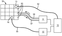
열적-제어가능 어레이(예컨대, 어레이(1))를 제어하기 위한 온도-제어가능 어레이(예컨대, 어레이(50 또는 150))의 사용이 도 7에 도시된 총칭적인 표현을 참고로 논의될 수 있다. 온도-제어가능 어레이(50)는, 어레이(50) 및 몰드 구성요소(5)의 외부에 존재하고 어레이(50)의 개별 요소(60)의 온도에 대한 정보를 온도 센서(13)로부터 (예컨대, 도 7의 총칭적인 표현으로 도시된 바와 같은 배선(52)을 통하여) 수신할 수 있는 제어기(10)에 작동식으로 연결될 수 있다. 제어기(10)는 (예컨대 배선(55)에 의해, 예컨대 어레이(50)의 개별 요소(60)에 열적으로 결합된 전기 히터(14)에 연결될 수 있는) 제1 열전달 메커니즘 제어 유닛(12)에 (예컨대, 도 7에 도시된 바와 같이 배선에 의해) 작동식으로 연결될 수 있어서, 제어기(10)가 어레이(50)의 다양한 요소(60)에 대한 제1 열전달 메커니즘의 적용 시에 제어 유닛(12)을 지시할 수 있도록 한다. 제어기(10)는 유사하게 (이동형 열전달 유체가 요소(60)의 동적 열전달 구조물과의 직접적으로 또는 간접적으로 접촉할 수 있도록, 예컨대 유체-공급 도관(56) 및 유체 배출 도관(57)에 의해, 어레이(50)의 개별 요소(60)에 연결될 수 있는) 제2 열전달 메커니즘 제어 유닛(11)에 (예컨대, 도 7에 도시된 바와 같이 배선에 의해) 작동식으로 연결될 수 있어서, 제어기(10)가 어레이(50)의 다양한 요소(60)에 대한 제2 열전달 메커니즘의 적용 시에 제어 유닛(11)을 지시할 수 있도록 한다. 편의상 단지 단일 온도 센서(13) 및 관련된 배선과, 단일 전기 요소(14) 및 관련된 배선과, (화살표로 표시된 이동 방향을 갖는) 이동형 열전달 유체를 이송하기 위한 중공 배관인 단일 세트의 공급/배출 도관들이 도 7에 도시되어 있지만, 그러한 구성요소들은 원하는 바와 같이 어레이(50)의 일부 또는 모든 개별 요소(60)를 위해 제공될 수 있다는 것이 이해될 것이다. (단열 스페이서, 에어 갭, 등은, 어레이(50)의 다양한 요소(60)들 사이에 존재할 수 있는 바와 같이, 명확성을 위하여 또한 생략되어 있다). 언급된 바와 같이, 일부 실시예에서, 제1 열전달 메커니즘은 정적 메커니즘(예컨대, 전기적 가열)일 수 있고, 제2 열전달 메커니즘은 동적 메커니즘(예컨대, 이동형 열전달 유체에 의한 열에너지의 전달)일 수 있다. 또한 언급된 바와 같이, 모든 요소(60)가 어레이의 다른 요소들과 상이한 온도로 제어될 필요는 없다(예를 들어, 2개 이상의 요소들이 하나의 블록으로 제어될 수 있다).The use of a temperature-controllable array (e.g.,
각각의 요소(60)가 공동 스킨(3)과 긴밀하게 접촉하는 표면(61)을 포함하는 본체의 일부(하중 지지 부재(62))로부터 측방향으로 오프셋된 열교환 모듈(부분)(63)을 포함하는 접근법을 도 2 내지 도 6에 도시된 일반적인 설계에서 사용한다는 것은 명백할 것이다. 그리고, 각각의 요소(60)는 열교환 모듈(63)을 포함하고, 열교환 모듈(63)은 인접한 요소(60)들의 열교환 모듈들의 방향으로부터 대향하는 방향으로 측방향으로 오프셋된다. 그러한 접근법이 예컨대 선형 (즉, 1 × N) 어레이(도 4의 예시적인 실시예에서는, 1 × 10 어레이가 도시됨)인 온도-제어가능 어레이(50)(및 성형 표면의 관련된 열적-제어가능 어레이)를 제공하는 데 특히 유용할 수 있다는 것은 명백할 것이다.A heat exchange module (portion) 63 offset laterally from a portion of the body (load bearing member 62) including a
다른 일반적인 설계가 도 8 및 도 9의 예시적인 실시예에 도시되어 있다. 이들 도면에 예시된 접근법은 비선형 어레이를 제공하는 데 특히 적합할 수 있고, 또한, 이는 그와 같이 열교환 모듈로의 그리고/또는 그로부터 전방 표면 - 전방 표면으로 그리고/또는 그로부터 열에너지가 공동 스킨 내로 교환됨 - 을 포함하는 본체의 다른 일부(예컨대, 하중 지지 부재) 내로의 열에너지의 전술된 측방향 전도에 좌우되지 않는다. 오히려, 온도-제어가능 어레이(150)의 각각의 요소(160)는 (앞서 도 1을 참조하여 설명된 바와 같이 공동 스킨 내에 열적-제어가능 어레이(1)의 픽셀(2)을 제공하도록) 공동 스킨의 배면 표면과 긴밀한 접촉으로 배치될 수 있는 전방 표면(161)을 갖는 하중 지지 본체(170)를 포함한다. 도 8 및 도 9의 설계에서, 각각의 요소(160)의 본체(170)의 사실상 모두는 하중 지지 상태일 수 있다. 즉, 어레이(150)가 몰드 구성요소 내로 포함되는 경우, 일부 또는 모든 요소(160)의 후방 표면(167)은 몰드 구성요소 자체, 몰드 베이스, 또는 지지 블록과 하중 지지 접촉 상태일 수 있다.Other general designs are shown in the exemplary embodiment of FIGS. 8 and 9. FIG. The approach illustrated in these figures may be particularly suited to providing a non-linear array, and it is also possible that heat energy is exchanged into and / or from the front surface-front surface to and / - < / RTI > of the thermal energy into another part of the body (e. Rather, each of the
도 9의 배면도에 도시된 바와 같이, 각각의 본체(170)는 적어도 하나의 개방된 단부를 갖는, 예컨대 후방으로 개방된 단부를 갖는, 공동(169)을 포함할 수 있고, 이 공동(169) 내로 전기적 가열 및/또는 냉각 디바이스가 삽입될 수 있다(도 9의 특정 실시예에서, 2개의 그러한 공동(169)이 구비된다). 이러한 방식으로, (전술된 제1 열전달 메커니즘과 유사할 것이며, 예컨대 정적 열전달 메커니즘일 수 있는) 하나의 열전달 메커니즘이 구비될 수 있다. 개별 본체(170)들 사이에는, 복수의 동적 열전달 튜브(즉, 이동형 열전달 유체의 통과를 허용하는 중공 튜브)(153)가 연장될 수 있는데, 열전달 튜브(153)의 외측 표면은 중공 튜브(153)의 그러한 외부 표면을 수용하도록 형상이 설정된 본체의 표면(166)과 긴밀하게 접촉한다. (하나의 그러한 튜브(153)가 도 8 및 도 9에서 생략되어 있어서, 표면(166)이 보다 분명하게 보여질 수 있다.) 따라서, 전술된 동적 열전달 구조물은 이동형 열전달 유체를 포함하는 열전달 튜브의 벽과 긴밀하게 접촉하도록 구성되는 그러한 구조물을 포함할 수 있다. 따라서, 이러한 유형의 배열은 (앞서 설명되었던 제2 동적 열전달 메커니즘과 유사할 것인) 제2 열전달 메커니즘을 제공할 수 있다. 열전달 튜브(153)들의 임의의 적합한 개수, 간격, 및 배열이 사용될 수 있다. 공통 열전달 유체가 모든 튜브(153)들을 통과할 수 있거나, 또는 일부 실시예에서, 상이한 온도의 유체들이 상이한 튜브(153)들을 통과할 수 있다.9, each
각각의 요소(160)에서, 개방된 단부를 갖는, 예컨대 후방 개방된 단부를 갖는, 공동(164)이 온도 센서(예컨대, 전술된 센서(13))를 위해 구비될 수 있다. 공동(164)의 개방된 단부가 편의상 본체(170)의 후방에 배치될 수 있으나, 공동(164)의 폐쇄 단부가 본체(170)(예컨대, 공동 스킨(3)에 가장 가까운 본체(170)의 일부)의 온도의 만족스러운 모니터링을 제공하도록 (예컨대, 본체(170)의 전방 표면(161)에 충분히 가깝게) 위치될 수 있다. 그러나, 본체(170)가 비교적 높은 열전도율의 재료로 제조되는 경우, 본체(170)의 임의의 편리한 위치에 온도 센서를 위치시키는 것이 가능할 수 있다.In each
요소(160)들은, 예컨대 요소(160)를 제 위치에 단단히 유지시키도록 조임가능하도록 (그리고 열전달 튜브(153)가 그에 인접하는 요소 표면들과 긴밀한 접촉 상태에 유지되는 것을 보장하도록) 다양한 요소들 사이에 구비된 공간을 통과할 수 있고 예컨대 어레이(150)의 측부들로부터 외향으로 연장될 수 있는 예컨대 볼트 등(도 8 또는 도 9에는 미도시)을 통하여 함께 유지될 수 있다. 원하는 경우, 지지 블록 볼트(예컨대, 전술된 볼트) 또는 다른 체결 메커니즘이 사용되어 어레이를 제 위치에 고정시킬 수 있도록 하는 지지 블록이 어레이(150)의 일부 또는 모든 측부 상에, 그리고/또는 후방에, 구비될 수 있다. 그러한 지지 블록은 유리하게는 단열 재료로 제조될 수 있다(그러나, 그러한 지지 블록은 그를 통하는, 예컨대 앞서 설명된 지지 블록(51)의 유체 유동 채널(53)에 의해 예시된 유형의, 유체 채널을 반드시 포함할 필요는 없다).The
각각의 요소(160)의 각각의 본체(170)는 전술된 바와 유사한 방식으로 각각의 인접한 요소의 본체로부터 측방향으로 단열될 수 있다. 도 8 및 도 9의 예시적인 실시예에서, 에어 갭(172)이 인접한 요소(160)들의 표면들 사이에 도시되어 있지만, 단열 스페이서(도 8 또는 도 9에서는 가시적이지 않음)가 또한 존재할 수 있다. 측방향 단열을 추가로 향상시키기 위하여, 열전달 튜브(153)는 비교적 낮은 열전도율을 갖는 재료로 제조될 수 있다. 다양한 실시예에서, 열전달 튜브(153)는 열전도율이 약 100, 80, 60, 또는 40 W/m-℃ 미만인 재료로 제조될 수 있다. 추가 실시예에서, 열전달 튜브(153)는 열전도율이 적어도 약 5, 10, 20 또는 25 W/m-℃인 재료로 제조될 수 있다. 특정 실시예에서, 열전달 튜브(153)는 강철, 예컨대 스테인리스 강철로 제조될 수 있다. 이동형 열전달 유체로부터 각각의 요소(160)의 각각의 본체(170)로의 동적 열전달을 가능하게 하기 위하여, 중공 열전달 튜브(153)는 비교적 얇은 벽을 포함할 수 있다. 따라서, 다양한 실시예에서, 열전달 튜브(153)는 약 1.0, 0.5, 또는 0.2 mm 미만의 벽 두께를 포함한다. 요약하면, 낮은 열전도율 재료로 제조된 얇은 벽을 갖는 동적 열전달 튜브(153)를 사용하여, 어레이의 요소들 사이의 측방향 단열이 그들 사이를 지나가는 튜브에 의해 감소될 수 있는 정도를 최소화하면서, 튜브 내의 이동형 열전달 유체와 어레이의 각각의 요소 사이의 열에너지의 원하는 교환을 허용할 수 있다.Each
온도-제어가능 어레이의 인접한 요소들의 본체들의 임의의 적합한 배열 및/또는 인접한 요소들의 본체들 사이의 측방향 (직접적인 또는 간접적인) 상호연결은 본 명세서에서 설명된 측방향 단열이 유지되는 한 허용될 수 있다는 것이 강조된다. 인접한 요소들의 본체들이 그들 사이에 개재된 낮은 열전도율 재료의 단열 스페이서를 어떻게 가질 수 있는지, 그들 사이에 이어지는 낮은 열전도율 재료로 제조된 동적 열전달 튜브를 어떻게 가질 수 있는지, 등은 이미 논의되어 왔다. 추가 실시예에서, 인접한 요소들의 본체들은 그들 사이에 개재된 지지 구조의 부재들을 (예컨대, 지지 격자가 일부 또는 모든 인접한 본체들 사이의 에어 갭의 일부 내에 끼워맞춤될 수 있고, 지지 격자는 어레이의 기계적 완전성(integrity)을 향상시킬 수 있음), 측방향 단열을 위한 전술된 조건을 보존하기 위하여 그러한 지지 부재들이 충분히 낮은 열전도율을 갖거나 그리고/또는 열에너지의 전도를 위해 충분히 작은 단면적을 포함하는 한, 가질 수 있다.Any suitable arrangement of the bodies of adjacent elements of the temperature-controllable array and / or lateral (direct or indirect) interconnection between the bodies of adjacent elements may be allowed as long as the lateral insulation described herein is maintained It is emphasized that How bodies of adjacent elements can have insulating spacers of low thermal conductivity material interposed between them, how to have a dynamic heat transfer tube made of a low thermal conductivity material therebetween, etc. have already been discussed. In a further embodiment, the bodies of adjacent elements may be configured to support members of a support structure interposed therebetween (e.g., the support grid may fit within a portion of the air gap between some or all adjacent bodies, So long as such supporting members have a sufficiently low thermal conductivity and / or a small enough cross-sectional area for the conduction of thermal energy, in order to preserve the above-mentioned conditions for lateral insulation, Lt; / RTI >
더 추가의 실시예에서, 소정의 인접한 요소들의 본체들을 연결하는 하나 이상의 일체형 가교 부분의 존재를 허용하는 것이 가능할 수 있다. 비록 그러한 가교 부분이 (어레이의 요소의 본체와 일체로 형성되어) 높은 열전도율을 가질 수 있다 하더라도, 그러한 가교 부분 또는 그의 일부 섹션이 (예컨대, 가교 부분의 그러한 작은 단면적 섹션이 열에너지의 전달에 대한 병목을 나타내도록) 인접한 본체들 사이의 열에너지의 전도를 위해 충분히 작은 단면적을 포함하는 한, 측방향 단열을 위한 전술된 조건을 만족시키는 것은 여전히 가능할 수 있다.In a still further embodiment, it may be possible to allow for the presence of one or more integral bridging portions connecting the bodies of certain adjacent elements. Although such bridging portions may have high thermal conductivities (formed integrally with the body of the elements of the array), such bridging portions or portions thereof (e.g., such small cross-sectional area sections of the bridging portion may be a bottleneck for thermal energy transfer It is still possible to satisfy the above-mentioned conditions for lateral insulation, as long as it includes a cross-sectional area small enough for conduction of thermal energy between adjacent bodies.
일부 실시예에서, 온도-제어가능 어레이(150)는 스킨에 반드시 부착되지는 않고서 공동 스킨(3)의 후방 표면의 구역과 긴밀한 열 접촉 상태로 위치될 수 있다(오히려, 어레이(150) 및 그의 개별 요소(160)들이 본 명세서에서 앞서 설명된 일반적인 유형의 하나 이상의 지지 블록에 의해 지지될 수 있고 공동 스킨에 대해 가압될 수 있다). 그러나, 도 8에 도시된 특정 실시예에서, 요소(160)의 각각의 본체(170)는 전방으로 개방된 단부를 갖는 공동(177)을 포함한다. 각각의 공동(177)은 공동 스킨(3)에 연결된 (예컨대, 그의 일체 부분인) 중공 보스(boss)를 수용하도록 구성될 수 있다. 그러한 중공 보스는 예컨대 본체(170)의 볼트 구멍(168)을 통과하는 볼트의 전방 단부를 나사결합가능하게 수용하도록 내부에 나사형성될 수 있다. 그러한 볼트는 어레이(150)를 공동 스킨(3)에 부착하는 데 사용될 수 있다(그리고, 어레이(150)의 후방 측 상에서, 어레이(150)를 예컨대 지지 블록, 몰드 베이스, 등에 부착하는 데 사용될 수 있다).In some embodiments, the temperature-
도 1 내지 도 9에 도시된 실시예가 본 명세서에서 개시된 접근법들을 예시하기 위하여 선택된 단지 예시적인 실시예라는 것은 강조되어야 한다. 변형예들이 가능하다는 것이 이해될 것이다. 예를 들어, 일부 실시예에서, 몰드 공동의 몰드 한정 표면의 적어도 일부를 제공하는 전방 표면을 포함하는 스킨(예컨대, 낮은 열전도율의 얇은 스킨)이 몰드 구성요소의 일부로서 구비될 수 있다. 즉, 그러한 스킨은 몰드 구성요소에 부착될 수 있고, 이어서 온도-제어가능 어레이(예컨대, 50 또는 150)는 몰드 구성요소의 스킨의 후방 표면과 긴밀히 접촉하게 될 수 있고 이어서 (스킨에 부착되든, 아니면 스킨에 실제로 부착되지 않고 단순히 그와 긴밀한 접촉 상태로 유지되든 간에) 제 위치에 유지될 수 있다. 다른 실시예에서, 스킨(예컨대, 낮은 전도율의 얇은 스킨)은 온도-제어가능 어레이(예컨대, 어레이(50 또는 150))의 일부로서 구비될 수 있다. 일부 특정 실시예에서, 별도로 제조된 스킨이 그러한 어레이의 요소들의 본체의 전방 표면에 부착될 수 있다. 다른 특정 실시예에서, 스킨이 어레이의 요소들의 본체의 전방 표면에 의해 직접적으로 제공될 수 있다. (그러한 실시예는 온도-제어가능 요소 위에 놓인 스킨의 두께 "t"가 본질적으로 영(0)인 극단적인 경우를 나타내는 것이 이해될 것이다.) 이러한 경우는 요소가 몰드 공동의 성형 표면의 일부를 제공하는 일체형 스킨을 포함하는 경우로 생각될 수 있다. 그러한 접근법에서, 스킨을 전방 측 상에 담지하는 (그러나 마련된) 어레이가 달리 이미 한정된 몰드 공동 표면 내의 개방 구역을 스킨이 충전하도록 (몰드 삽입체에 유사한 방식으로) 몰드 구성요소의 제공된 공간 내에 끼워맞춤될 수 있다.It should be emphasized that the embodiments shown in Figures 1 to 9 are merely exemplary embodiments selected to illustrate the approaches disclosed herein. It will be appreciated that variations are possible. For example, in some embodiments, a skin (e.g., a thin skin of low thermal conductivity) that includes a front surface that provides at least a portion of the mold defining surface of the mold cavity may be provided as part of the mold component. That is, such a skin can be attached to a mold component, and then a temperature-controllable array (e.g., 50 or 150) can be brought into intimate contact with the back surface of the skin of the mold component, Or it may be held in place, whether it is actually attached to the skin or simply kept in intimate contact therewith. In another embodiment, a skin (e.g., a thin skin with a low conductivity) may be provided as part of a temperature-controllable array (e.g.,
2가지 예시적인 설계의 온도-제어가능 어레이들(50, 150) 및 대응하는 열적-제어가능 어레이(1)들은 본 명세서에 나타나 있다. 이들은 단지 예시적인 설계이고, 그러한 어레이의 설계는 이들 예시적인 실례로부터 다양하게 변형될 수 있다는 것이 인정될 것이다. 예를 들어, 다양한 실시예에서, 어레이(1)의 픽셀(2)들의 개수는 예컨대 2, 3, 4, 6, 8, 10, 16 이상의 범위일 수 있다. 다양한 실시예에서, 개별 픽셀(2)의 크기는 적어도 약 0.2, 0.4, 1.0, 2, 또는 5 제곱 센티미터일 수 있다. 추가 실시예에서, 개별 픽셀(2)의 크기는 최대 약 100, 50, 25, 10, 5, 2, 또는 1.0 제곱 센티미터일 수 있다. 다양한 실시예에서, 픽셀(2)들의 서로로부터의 중심-대-중심 간격(또는, 도심-대-도심 간격)은 적어도 약 0.2, 0.4, 1.0, 2.0, 또는 5.0 센티미터일 수 있다. 추가 실시예에서, 픽셀(2)들의 서로로부터의 중심-대-중심 간격은 최대 약 10, 5, 4, 2, 1, 또는 0.5 센티미터일 수 있다. 일부 실시예에서, 적어도 하나의 픽셀(2)의 적어도 하나의 주연 에지는 인접한 픽셀(2)의 주연 에지의 약 5 mm 이내에 있을 수 있다. 추가 실시예에서, 적어도 하나의 픽셀(2)의 적어도 하나의 주연 에지는 인접한 픽셀(2)의 주연 에지의 약 2, 1, 또는 0.5 mm 이내에 있을 수 있다. 다양한 실시예에서, 임의의 특정 픽셀(2)은 다른 픽셀(2)의 것과는 상이한 형상 및/또는 크기를 포함할 수 있고, 규칙적인 또는 불규칙적인 형상을 포함할 수 있다. 다양한 실시예에서, (픽셀(2)에 의해 집합적으로 공급되고, 다양한 픽셀들 사이에 산재될 수 있는 임의의 픽셀 외 구역(들)을 포함하지 않는) 어레이(1)의 전체 면적은 적어도 약 2, 5, 10, 20, 또는 50 제곱 센티미터일 수 있다. 추가 실시예에서, 어레이(1)의 전체 면적은 최대 약 10000, 500, 200, 또는 100 제곱 센티미터일 수 있다. 다양한 실시예에서, 어레이(또는 어레이들)의 픽셀들에 의해 집합적으로 제공되는 전체 면적은 몰드 공동(8)의 전체 표면의 약 50, 30, 20, 10, 또는 5% 미만을 포함할 수 있다. 다양한 실시예에서, 어레이(또는 어레이들)의 픽셀들에 의해 집합적으로 제공되는 전체 면적은 몰드 공동(8)의 전체 표면의 약 50, 70, 80, 90, 또는 95% 초과를 포함할 수 있다.Two exemplary design temperature-
다양한 실시예에서, 어레이(1)는, 본 명세서에서 앞서 설명된 바와 같이, 선형 어레이 또는 비선형 어레이일 수 있다. 다양한 실시예에서, 어레이(1)는 (예컨대, 도 1에 도시된 대칭 어레이의 하나의 예시적인 설계를 갖는 적어도 하나의 대칭 축을 포함하는) 대칭일 수 있거나, 또는 비대칭일 수 있다. 일부 실시예에서, 일부 또는 모든 픽셀(2)은 (예컨대, 픽셀들의 아래에 놓인 온도-제어가능 요소들 사이에 측방향으로 구비된 개재된 갭/단열 장벽 위에 놓일 수 있는 그러한 영역을 제외하고는, 표면(4)의 픽셀 외 구역이 그들 사이에 거의 없거나 전혀 없는) 다른 픽셀(2)에 인접할 수 있어서, (예컨대, 도 1에 예시된 바와 같이) 예컨대 인접한 어레이를 집합적으로 형성하도록 한다. 다른 실시예에서, 적어도 하나의 픽셀은, 도 10을 참조하여 본 명세서에서 이후에 논의되는 바와 같이, 표면(4)의 픽셀 외 구역(예컨대, 몰드 구성요소의 온도가 제어되지 않는 부분 위에 놓이는 표면(4)의 구역)에 의해 다른 픽셀 또는 픽셀들로부터 분리될 수 있다. 다양한 실시예에서, 어레이의 픽셀은 약 10, 5, 2, 또는 1 mm 미만만큼 (가장 인접한 에지-대-가장 인접한 에지 거리로) 그의 가장 인접한 이웃으로부터 측방향으로 분리될 수 있다. 다른 실시예에서 하나 이상의 픽셀은 2개의 가장 인접한 이웃 픽셀들의 가장 인접한 에지들이 적어도 약 0.5, 1, 또는 5 cm만큼 서로로부터 측방향으로 분리되도록 어레이의 다른 픽셀(들)로부터 측방향으로 분리될 수 있다.In various embodiments, the
더 추가의 변형예가, 예컨대 도 10의 예시적인 방식으로 도시된 바와 같이, 가능하다. 예를 들어, 어레이(1)의 픽셀(2)은 반드시 임의의 종류의 규칙적인 간격 또는 패턴으로 제공되어야 하는 것은 아니다(예시적인 불규칙 패턴이 도 10의 어레이(1')의 픽셀(2', 2'', 2''', 2'''')에 의해 제공된다). 도 10은 또한 픽셀(2'''')이 표면(4)의 픽셀 외 구역에 의해 다른 픽셀로부터 분리되는 경우를 도시한다. 더욱이, 일부 실시예에서, 하나 이상의 픽셀은 어레이의 다른 픽셀 내에 부분적으로 또는 완전히 측방향으로 포함될 (예컨대, 그에 의해 둘러싸일) 수 있다(이에 대한 예는 픽셀(2', 2'', 2''')이 픽셀(2) 내에 측방향으로 포함된 도 10에 도시되어 있다). 필요한 모든 것은 픽셀들이 온도-제어가능 어레이에 의해 제공되는 것인데, 본 명세서에서 설명되는 바와 같이, 온도-제어가능 어레이는 예컨대 적어도 2개가 서로로부터 측방향으로 단열된 개별 온도-제어가능 요소들을 포함한다. 예를 들어 (도 10의 특정 실시예에 대해), (예컨대 단열 스페이서를 포함하는) 개재 공간이 픽셀(2', 2'', 2''') 아래에 각각 놓이는 온도-제어가능 요소들의 각각을 측방향으로 둘러쌀 수 있어서, 픽셀(2) 아래에 놓인 온도-제어가능 요소로부터 이들 온도-제어가능 요소들을 측방향으로 단열시키도록 한다.Further further variations are possible, for example as shown in the exemplary manner of Fig. For example, the
앞서 논의된 임의의 설계의 어레이 및 배열은 도 7을 참조로 앞서 논의된 바와 같은 일반적인 방식으로 제어기, 온도 센서, 제1 및 제2 열전달 메커니즘 제어 유닛, 등에 작동식으로 연결될 수 있고, 본 명세서에서 앞서 논의된 바와 같은 폐루프 제어의 대상이 될 수 있다.Arrays and arrangements of any design discussed above may be operatively connected to the controller, the temperature sensor, the first and second heat transfer mechanism control units, etc. in a general manner as discussed above with reference to Figure 7, May be subject to closed loop control as discussed above.
다양한 실시예에서, 다수의 온도-제어가능 어레이(예컨대, 50 및/또는 150)들 및 대응하는 열적-제어가능 어레이(1)들이 단일 몰드 공동의 스킨의 상이한 영역들에 구비될 수 있다. 원하는 경우, 제1 몰드 구성요소에 구비되는 하나 이상의 그러한 어레이에 더하여, (합쳐져서 몰드 공동을 형성하는 제1 몰드 구성요소(종종 A 측 구성요소라 함) 및 제2 몰드 구성요소(종종 B 측 구성요소라 함)를 종래의 사출 성형이 포함한다는 것을 유의하면) 하나 이상의 그러한 어레이가 제2 몰드 구성요소 내에 구비될 수 있다. 각각이 하나 이상의 그러한 어레이를 포함하는 다수의 몰드 공동들이, 원하는 경우, 단일 사출 성형 장치 내에 구비될 수 있다. 일부 실시예에서, 열적-제어가능 어레이를 포함하는 공동 스킨 영역의 전체는 대체로 평면, 또는 엄격히 평면일 수 있고, 다른 실시예에서, 열적-제어가능 어레이를 포함하는 공동 스킨의 적어도 일정 구역들은 비-평면(예컨대, 곡면)일 수 있다.In various embodiments, multiple temperature-controllable arrays (e.g., 50 and / or 150) and corresponding thermally-
본 명세서에서 개시된 바와 같은 온도-제어가능 어레이 또는 어레이들과, 이들의 임의의 구성요소들 및 이를 구비한 구성요소들은 임의의 적합한 사출 성형 시스템과 함께 사용될 수 있다. 언급된 바와 같이, 그러한 어레이 또는 어레이들은 (예컨대 본 명세서에서 앞서 설명된 바와 같이 하나 이상의 지지 블록을 직접적으로 또는 간접적으로 거쳐서) 몰드 구성요소(예컨대, 도 1에서 총칭적인 표현으로 도시된 바와 같은 몰드 구성요소(5))에 부착되고 그에 의해 지지될 수 있다. 그러한 몰드 구성요소는 편의상, 다른 몰드 구성요소와 함께 합쳐져서 몰드 공동 또는 공동들을 형성할 수 있는, 종종 몰드 부품이라 불리고 하나 이상의 개방된 단부를 갖는 공동들이 내부에 있는 예컨대 금속으로 제조된 종래의 몰드 구성요소일 수 있다. 그러한 몰드 구성요소는 그 자신이 예컨대 종래의 몰드 베이스에 의해 지지될 수 있다. 그러한 몰드 베이스(어떠한 도면에도 도시되지 않음)는 사출 성형 시스템의 플래튼(마찬가지로, 어떠한 도면에도 도시되지 않음)에 부착되고 그에 의해 지지될 수 있다. (당업자는 그러한 몰드 구성요소, 몰드 베이스, 및 플래튼에 친숙할 것이다).Temperature-controllable arrays or arrays, as well as any of the components and components thereof, as disclosed herein can be used with any suitable injection molding system. As noted, such arrays or arrays may be used to form mold components (e. G., Molds as shown in generic representation in Figure 1) (e. G., Through < (E.g., component 5). Such a mold component may be, for convenience, a conventional mold construction, for example made of metal, in which cavities, often referred to as mold parts and having at least one open end, are internal, which can be combined with other mold components to form mold cavities or cavities Lt; / RTI > Such a mold component may itself be supported by, for example, a conventional mold base. Such a mold base (not shown in any of the drawings) may be attached to and supported by a platen of the injection molding system (likewise not shown in any drawings). (Those skilled in the art will be familiar with such mold components, mold bases, and platens).
그러한 어레이 또는 어레이들은 예컨대 사출 성형 시스템의 (종종 "A" 측 또는 "A" 플레이트라고 하는) 부동형(unmoving) 측의 제1 몰드 구성요소와 조합하여 제공(예컨대 그에 부착)될 수 있다. 그러한 사출 성형 시스템은, 예컨대 (도 1을 참조하면) 제1 몰드 구성요소(5)로부터 몰드 공동(8)의 먼 측에 위치된 제2 몰드 구성요소(7)를 (예컨대, 제2 종래의 몰드 베이스를 거쳐) 지지하는 제2 플래튼을 포함할 수 있는데, 제2 몰드 구성요소는 제1 플래튼 및 제2 플래튼이 합쳐진 경우 몰드 공동(8)을 한정하도록 제1 몰드 구성요소(5)의 성형 표면(4)과 (그리고 몰드 구성요소(5)에 의해 제공될 수 있는 임의의 다른 성형 표면과) 조합되는 하나 이상의 성형 표면을 제공할 수 있다. 일부 실시예에서, 제2 플래튼은 적어도 하나의 몰드 공동이 정합된 제1 및 제2 몰드 구성요소들에 의해 한정되는 제1 위치로 제1 플래튼을 향하여, 그리고 성형 부품이 몰드 공동으로부터 제거될 수 있는 제2 위치로 (이 경우, 제2 몰드 구성요소는 종종 "B" 측 또는 플레이트라 하는 유형의 것임) 제1 플래튼으로부터 멀리 이동가능할 수 있다. 앞서 논의된 바와 같이, "B" 측 몰드 구성요소의 몰드 공동 표면은 원하는 경우 하나 이상의 열적-제어가능 어레이를 포함할 수 있다.Such arrays or arrays may be provided (e.g., attached thereto) in combination with a first mold component on the unmoving side of the injection molding system (often referred to as the "A" side or "A" plate). Such an injection molding system may include a
사출 성형이 용융 수지를 몰드 공동 내로 주입하고 이어서 공동 내의 수지가 냉각되어 수지를 성형 부품으로 응고시키는 것을 포함하는 것이라면, 임의의 적합한 장치 및 관련된 구성요소들은 중합체 수지를 용용하고 용융 수지를 몰드 공동(들) 내로 공급하는 데 사용될 수 있는데; 그 예는 왕복 스크류 장치, 스크류-오버-플런저(screw-over-plunger) 장치, 등이다(게다가, 그러한 구성요소들은 도 1의 몰드 공동 및 성형 구성요소들의 단순화된 표현에 도시되어 있지 않다). 제1 저온의 유동가능 수지를 몰드 공동 내로 주입하고 이어서 공동 내의 수지가 가열되어 수지를 고체 부품으로 가교결합시키는 화학반응을 촉진하는 것을 포함하는 것(즉, 소위 반응 사출 성형의 임의의 변형)이라면, 임의의 적합한 반응 사출 성형 장치 및 관련된 구성요소들은 그러한 유동가능 수지를 주입하고 이어서 화학반응 및 그의 응고를 촉진시키는 데 사용될 수 있다.If the injection molding involves injecting the molten resin into the mold cavity and then cooling the resin in the cavity to solidify the resin into a molded part, any suitable device and related components may be used to melt the polymer resin and melt the molten resin into the mold cavity RTI ID = 0.0 > (s) < / RTI > Examples are reciprocating screw devices, screw-over-plunger devices, etc. (Furthermore, such components are not shown in the simplified representation of the mold cavity and molding components of FIG. 1). (I. E., Any variation of so-called reactive injection molding) that involves injecting a first low temperature flowable resin into the mold cavity and then heating the resin in the cavity to crosslink the resin to the solid component , Any suitable reaction injection molding apparatus and associated components can be used to inject such flowable resin and subsequently to promote the chemical reaction and its solidification.
일부 실시예에서, 온도-제어가능 어레이 및 대응하는 열적-제어가능 어레이는 높은 사출 압력 성형에 사용될 수 있다. 이러한 경우, 어레이의 하나 이상의 개별 요소의 본체의 적어도 일부는 (그러한 일부가, 요소(60)에서와 같이, 요소의 하중 지지 부재이든 또는 그러한 일부가, 요소(160)에서와 같이, 요소의 본체의 사실상 모두이든 간에) (몰드 구성요소들이 가압 하에서 합쳐지는 경우 수립되는) 하중 경로의 세그먼트를 제공할 수 있고, 따라서 그러한 높은 압력을 견딜 필요가 있을 수 있다.In some embodiments, temperature-controllable arrays and corresponding thermally-controllable arrays may be used for high injection pressure molding. In this case, at least a portion of the body of the one or more discrete elements of the array (such a portion being a load bearing member of the element, such as in
높은 사출 압력의 사용을 가능하게 하기 위하여, 몰드 구성요소들은 종종, 공동의 대체로 대향하는 면들 상에 있는 몰드 공동 표면들(즉, "A" 측 몰드 구성요소에 의해 제공되는 몰드 공동 표면들 및 "B" 측 몰드 구성요소에 의해 제공되는 몰드 공동 표면들)의 상대 이동을 최소화하도록 설계된다. 몰드 구성요소들을 함께 클램핑하는 동안 분리선을 형성하는 몰드 구성요소들의 접촉 표면들이 "사전 하중을 받을" 수 있어서 이후에 주입되는 유동가능 수지의 압력이 사전 하중을 초과하지 않아야 한다는 것을 당업자는 이해할 것이다(이는 갭이 접촉 표면들 사이에 형성되게 할 수 있고 따라서 가능하게는 수지의 갭 내로의 용인할 수 없는 내비침을 야기할 수 있다). 이를 달성하기 위하여, 하중 경로는 피크 사출 압력과 몰드 공동의 투영 면적을 곱한 값보다 큰 압축 (사전)-하중을 견딜 수 있어야 한다. 이의 결과로, 적어도 일부 실시예에서, 예컨대 20000 psi 이상의 (몰드 공동 내에서 측정된) 피크 수지 사출 압력을 포함하는 (그리고 따라서 그러한 사출 압력과 함께 사용하기 위한 상응하는 정도의 사전 하중을 포함하는) 사출 성형 작업에서 본 명세서에서 설명되는 바와 같은 온도-제어가능 어레이를 사용하는 것이 바람직할 수 있다. 따라서, 다양한 실시예에서, 본 명세서에서 설명되는 바와 같은 온도-제어가능 어레이는 적어도 15000, 20000, 25000, 또는 30000 psi인 (몰드 공동 내에서 측정된) 사출 압력과 양립가능하도록 구성될 수 있다. 본 기술 분야에서 알려진 성형의 소정 방법(예컨대, 소위 적응형 냉각 등을 포함하는 방법)은 이들 실시예에 포함되지 않는다는 것은 이해될 것이다.In order to enable the use of high injection pressures, mold components are often placed on mold cavity surfaces (i.e., the mold cavity surfaces provided by the "A" side mold component and the mold cavity surfaces on the generally opposing sides of the cavity, Quot; B "-side mold components). It will be appreciated by those skilled in the art that the contact surfaces of the mold components forming the parting line during the clamping of the mold components together can receive a "preloaded" so that the pressure of the subsequently flowable resin does not exceed the preload This may cause a gap to be formed between the contact surfaces and thus possibly cause unacceptable immersion into the gap of the resin). To achieve this, the load path must be able to withstand a compression (pre) load greater than the peak injection pressure multiplied by the projected area of the mold cavity. As a result of this, in at least some embodiments, the peak resin injection pressure (including, for example, the corresponding pre-load for use with such injection pressure), including, for example, peak resin injection pressures (measured in the mold cavity) It may be desirable to use a temperature-controllable array as described herein in an injection molding operation. Thus, in various embodiments, the temperature-controllable array as described herein can be configured to be compatible with an injection pressure (measured in the mold cavity) of at least 15,000, 20000, 25000, or 30000 psi. It will be appreciated that certain methods of forming known in the art (e.g., methods including so-called adaptive cooling, etc.) are not included in these embodiments.
가장 넓은 의미에서, 앞서 논의된 접근법들은 온도-제어가능 어레이의 다수의 요소의 제공을 허용하고, 그 요소의 적어도 일부의 온도는 폐루프 방식으로 개별적으로 모니터링될 수 있다(그러나, 몇몇 경우에, 모든 요소가 성형 작업 동안 항상, 반드시 모니터링 및/또는 제어되어야 하는 것은 아닐 수 있다는 것을 명심하여야 한다). 더욱이, 각각의 그러한 요소 내로의 그리고/또는 그로부터의 열에너지의 전달은 제1 열전달 메커니즘에 의해서 (예컨대 전기 히터 또는 냉각기의 사용에 의해서) 뿐만 아니라 제1 메커니즘과 상이한 제2 열전달 메커니즘에 의해서 (예컨대, 이동형 열전달 유체의 사용에 의해 달성되는 바와 같은 동적 열전달에 의해서) 수행될 수 있다. 요소의 모니터링된 온도에 나타나는 바와 같은, 둘 모두의 열전달 메커니즘의 조합된 효과는 평가될 수 있고, 열전달 메커니즘의 하나 또는 둘 모두는 주어진 설정값으로 요소의 온도를 유지시키는 것, 온도를 새로운 설정값으로 변화시키는 것, 외부 영향(예컨대, 몰드 공동을 고온으로 용융된 수지로 충전함)에 응답하여 온도를 설정값으로 복귀시키는 것, 등에 사용될 수 있다.In the broadest sense, the approaches discussed above allow the provision of multiple elements of a temperature-controllable array, and the temperature of at least some of the elements can be individually monitored in a closed-loop fashion (however, in some cases, It should be noted that not all elements are necessarily necessarily monitored and / or controlled during the molding operation). Moreover, the transfer of thermal energy into and / or from each such element can be facilitated by a first heat transfer mechanism (e.g., by the use of an electric heater or cooler) as well as by a second heat transfer mechanism (e.g., By dynamic heat transfer as achieved by use of a mobile heat transfer fluid). The combined effect of both heat transfer mechanisms, such as those shown in the monitored temperature of the element, can be evaluated, and one or both of the heat transfer mechanisms can be used to maintain the temperature of the element at a given set point, , Returning the temperature to a set point in response to external influences (e.g., filling the mold cavity with molten resin at a high temperature), and the like.
따라서, 폐루프 방식으로 2개의 상이한 열전달 메커니즘을 어레이의 적어도 하나의 동일한 요소에 적용, 예컨대 대체로 동시 적용시키는 것, 및 그러한 제어 방식을 어레이의 다수의 요소에 적용시키는 것은 본 명세서에 개시되어 있다. 2개의 그러한 메커니즘의 대체로 동시에 사용하는 것은 몰드 공동의 온도의 정밀 제어를 허용하는 데 유의한 이점을 나타낼 수 있다는 것이 이해될 것이다. 예를 들어, 온도-제어가능 어레이의 제1 세트의 요소들(예컨대, 적어도 하나의 요소)은 제1 열전달 메커니즘 단독의 대상이 될 수 있다(그러한 제1 메커니즘은, 임의의 다른 메커니즘의 부재 시에, 제1 요소들 모두를 동일한 온도로 유지할 수 있는 것, 유사한 속도로 이들 모두의 온도를 변화시킬 수 있는 것, 등일 수 있다). 어레이의 제2 세트의 요소들(예컨대, 적어도 하나의 요소)은 제1 열전달 메커니즘(제1 세트의 요소들에 적용되는 제1 메커니즘과 동일할 수 있는 것으로, 예컨대, 제1 및 제2 세트들의 요소들 모두가 공통 열전달 유체에 의해 냉각될 수 있음)의 대상이 될 수 있다. 그리고, 제2 세트의 요소들은 또한 제1 열전달 메커니즘과 상이한 제2 열전달 메커니즘의 대상일 수 있다. 따라서, 이러한 제2 열전달 메커니즘은 제2 세트의 요소들 내의 제1 열전달 메커니즘의 효과를 상쇄시키거나 또는 증가시킬 수 있다(그리고, 제2 세트의 상이한 요소들에서 상이한 정도들로 그렇게 할 수 있다). 예를 들어, 어레이의 모든 요소는 공통 열전달 유체에 의해 냉각될 수 있고; 동시에, 어레이의 일부 요소는 높은 양의 가열 전력을 수신할 수 있고, 일부 요소는 낮은 양의 가열 전력을 수신할 수 있고, 그리고 일부 요소는 가열 전력을 결코 수신하지 않을 수 있다. 따라서, (몇몇 경우에 서로에 대해 부분적으로 상쇄될 수 있고 몇몇 경우에 서로를 증가시킬 수 있는) 2개의 열전달 메커니즘들 사이의 균형이 다수 요소 어레이의 각각의 요소에 대해 수립될 수 있다. 각각의 요소의 온도에 대한 대립되는 메커니즘들의 효과가 모니터링될 수 있고, 메커니즘의 하나 또는 둘 모두는, 예컨대 어레이의 상이한 요소들이 상이한 온도들로 유지되게 하도록, 원하는 바와 같이 변경될 수 있다.Thus, it is disclosed herein that two different heat transfer mechanisms in a closed loop fashion are applied to at least one identical element of the array, e.g., substantially simultaneous application, and that such control method is applied to multiple elements of the array. It will be appreciated that alternative use of two such mechanisms simultaneously may represent a significant advantage in allowing precise control of the temperature of the mold cavity. For example, the first set of elements (e.g., at least one element) of the temperature-controllable array may be the object of the first heat transfer mechanism alone (such a first mechanism may be any other mechanism, The ability to keep all of the first elements at the same temperature, the ability to vary both of these temperatures at a similar rate, etc.). The elements of the second set of arrays (e.g., at least one element) may be the same as the first heat transfer mechanism (which may be the same as the first mechanism applied to the elements of the first set, e.g., All of the elements can be cooled by a common heat transfer fluid). And the second set of elements may also be the subject of a second heat transfer mechanism different from the first heat transfer mechanism. Thus, this second heat transfer mechanism can offset or increase the effects of the first heat transfer mechanism in the second set of elements (and can do so to different degrees in the second set of different elements) . For example, all elements of the array can be cooled by a common heat transfer fluid; At the same time, some elements of the array may receive a high amount of heating power, some elements may receive a low amount of heating power, and some elements may never receive heating power. Thus, a balance between the two heat transfer mechanisms (which in some cases can be partially canceled against each other and in some cases to increase one another) can be established for each element of the multiple element array. The effect of the opposing mechanisms on the temperature of each element can be monitored, and one or both of the mechanisms can be changed as desired, e.g., to cause different elements of the array to be maintained at different temperatures.
2개의 상이한 열전달 메커니즘들을 대체로 동시에 적용하는 것의 개념은 그러한 메커니즘들이 사출 성형 사이클 동안 적어도 어느 시간에 동일한 온도-제어가능 요소에 동시에 적용되는 경우를 포함한다. 이는 또한, 반드시 정확히 동시에 적용되는 것이 아니더라도 (예를 들어, 메커니즘 각각이 성형 사이클의 한 단계 동안, 예컨대 몰드 공동의 냉각 동안, 예컨대 연 이어서 그리고/또는 신속하게 교호하는 방식으로 적용되도록 사이클링이 온(on) 및 오프(off)될 수 있음), 2개의 상이한 열전달 메커니즘들이 성형 사이클 동안 동일한 온도-제어가능 요소에 적용되는 경우를 포함한다.The concept of applying two different heat transfer mechanisms substantially simultaneously involves the case where such mechanisms are applied simultaneously to the same temperature-controllable element at least at any time during the injection molding cycle. This also means that the cycling is turned on so that, for example, each of the mechanisms is applied during one stage of the molding cycle, for example during cooling of the mold cavity, for example in a series and / on and off), two different heat transfer mechanisms are applied to the same temperature-controllable element during the molding cycle.
본 명세서에서 설명되는 바와 같은 배열은, 예를 들어 몰드 공동의 열적-제어가능 어레이(1)의 구별적인 열적 제어를 수행하기 위하여, 사용될 수 있는데, 이는 어레이의 적어도 하나의 픽셀이 어레이의 적어도 하나의 다른 픽셀의 온도와 예컨대 섭씨 5도 이상만큼 상이한 온도로 될 수 있고/있거나 그 온도로 유지될 수 있다는 것을 의미한다. 그러한 구별적인 열적 제어는 픽셀들이 임의의 최소 기간 동안 그러한 상이한 온도들에서 반드시 유지되는 것을 (예컨대, 이들이 그러한 상이한 온도들에서 일정하게 유지되는 것을), 또는 온도들이 실제로 모니터링되는 것을 필요로 하지 않는다는 것에 유의한다. 그리고, 몇몇 경우에, 2개 이상의 픽셀은 유사한 또는 사실상 동일한 온도로 유지될 수 있다(예를 들어, 몇몇 픽셀들은 블록으로서 조합하여 제어될 수 있다). 다양한 실시예에서, 어레이의 적어도 하나의 픽셀은 어레이의 다른 픽셀의 온도와 적어도 섭씨 약 10, 20, 또는 40도만큼 상이한 온도로 구별적으로 열적으로 제어될 수 있다.The arrangement as described herein can be used, for example, to perform distinct thermal control of the thermally-
예컨대 열에너지가 하나의 열전달 메커니즘에 의해 개별 요소 내로 전달될 수 있고 상이한 제2 열전달 메커니즘에 의해 요소로부터 능동적으로(actively) 제거될 수 있는 본 명세서에서 개시된 접근법은 요소로부터 (예컨대, 점진적인 전도성 발산에 의해) 수동적으로(passively) 제거되는 것을 통하여 예컨대 하나의 메커니즘에 의해 전달되는 열에너지가 요소를 단지 떠날 수 있게 하는 방법들에 비해 유의한 이점을 가질 수 있다는 것이 이해될 것이다. 어레이의 2개의 상이한 픽셀들이 상이한 일정 온도들로 제어되어야만 한다는 것이 (또는, 어레이의 임의의 특정 픽셀이 특정의 일정 온도로 제어되어야만 한다는 것이) 반드시 요구되지는 않는다는 것도 또한 이해되어야 한다. 오히려, 제1 및/또는 제2 열전달 메커니즘은 예컨대 어레이의 하나 이상의 요소의 온도가 변하고 있는 증감 속도(ramping rate)를 제어하는 데 사용될 수 있다. 더욱이, 온도-제어가능 어레이의 요소들의 온도의 제어는 반드시, 몰드 공동 표면의 관련된 열적-제어가능 어레이의 대응하는 픽셀들이 동일한 정확한 이들 온도로 제어되도록 하지 않을 수 있다(그러나, 이는 몇몇 경우에 있을 수 있다). 온도-제어가능 어레이의 다수 온도-제어가능 요소들의 사용은, 예컨대 온도-제어가능 요소들과 물리적으로 유사할 수 있으면서 반드시 능동적으로 제어되지는 않는 다른 요소들의 존재를 배제하지 않는다는 것이 또한 이해될 것이다(몇몇 경우에, 그러한 요소의 온도는 심지어 모니터링도 되지 않을 수 있다).For example, the approach disclosed herein, in which thermal energy can be transferred into a separate element by one heat transfer mechanism and actively removed from the element by a different second heat transfer mechanism, can be removed from the element (e.g., by progressive conductive diffusion ) It will be appreciated that through passive elimination, for example, thermal energy delivered by one mechanism may have significant advantages over methods that only allow the element to leave. It should also be understood that two different pixels of the array must be controlled at different constant temperatures (or that any particular pixel of the array must be controlled at a certain constant temperature). Rather, the first and / or second heat transfer mechanism may be used, for example, to control the ramping rate at which the temperature of one or more elements of the array is changing. Moreover, control of the temperature of the elements of the temperature-controllable array may not necessarily allow corresponding pixels of the associated thermally-controllable array of mold cavity surfaces to be controlled to the same exact temperature (however, . It will also be appreciated that the use of a plurality of temperature-controllable elements of the temperature-controllable array does not preclude the presence of other elements that may, for example, be physically similar to temperature-controllable elements but not necessarily actively controlled (In some cases, the temperature of such elements may not even be monitored).
본 명세서에서 설명되는 바와 같은 그러한 어레이의 사용은 예컨대 비교적 복잡한 형상의 성형 부품, 특히 비교적 두꺼운 섹션에 인접하게 비교적 얇은 섹션을 가질 수 있는 부품의 생산에 유리하게 사용될 수 있다는 것이 이해될 것이다. 특히 이러한 경우에, 본 명세서에서 설명되는 바와 같은 어레이의 사용은 더 균일한 몰드 충전, 최종 성형 부품 내의 감소된 응력, 등을 제공할 수 있다. 일부 실시예에서, 그러한 어레이는 용융된 열가소성 수지가 공동 내로 주입되고 이어서 냉각되어 수지를 성형 부품으로 응고시키는 잘 알려진 유형의 사출 성형에 이용될 수 있다. 어레이(또는 어레이들)의 구별적인 열적 제어는, 임의의 적합한 배열에 따라, 예컨대 수지를 공동 내로 주입하는 동안, 그리고/또는 수지를 냉각하여 응고시키는 동안, 수행될 수 있다. 그러한 어레이는 또한, (반응성, 가교결합성, 등인 임의의 적합한 분자, 올리고머, 중합체, 등을 포함하는) 유동가능 수지가 공동 내로 주입되고 이어서 가열되어 유동가능 수지를 성형 부품으로 응고시키는 하나 이상의 유형의 화학반응을 촉진하도록 하는 소위 반응성 사출 성형에 사용될 수 있다. 어레이(또는 어레이들)의 구별적인 열적 제어는, 임의의 적합한 배열에 따라, 예컨대 수지를 공동 내로 주입하는 동안, 그리고/또는 수지를 가열하여 응고시키는 동안, 수행될 수 있다.It will be appreciated that the use of such an array as described herein may be advantageously used, for example, in the production of molded parts of relatively complex shapes, particularly those that may have relatively thin sections adjacent to relatively thick sections. In particular in this case, the use of an array as described herein can provide more uniform mold filling, reduced stress in the final molded part, and the like. In some embodiments, such arrays can be used in injection molding of the well known type wherein the molten thermoplastic resin is injected into a cavity and then cooled to solidify the resin into a molded part. Distinctive thermal control of the arrays (or arrays) may be performed according to any suitable arrangement, for example during injection of the resin into the cavity and / or while the resin cools and cools. Such an array may also include one or more types of fluidizable resins (including any suitable molecules, oligomers, polymers, etc., which are reactive, crosslinkable, etc.) that are injected into the cavity and subsequently heated to solidify the flowable resin into a molded part So-called reactive injection molding, which promotes the chemical reaction of the polymer. Distinctive thermal control of the arrays (or arrays) can be performed according to any suitable arrangement, for example during injection of the resin into the cavity and / or while heating and solidifying the resin.
예시적인 실시예의 목록List of exemplary embodiments
실시예 1. 사출 성형 장치로서, 적어도 전방 표면을 포함하는 스킨을 포함하는 몰드 구성요소를 포함하고, 스킨은 스킨의 전방 표면이 몰드 공동의 성형 표면의 일부를 한정하는 적어도 하나의 영역을 포함하고, 몰드 구성요소는 또한 적어도 하나의 온도-제어가능 어레이를 포함하고, 상기 온도-제어가능 어레이는 스킨의 적어도 하나의 영역의 구역들에서 스킨에 열적으로 결합되어 구역들이 스킨의 전방 표면 내에 열적-제어가능 어레이를 집합적으로 제공하게 하는 복수의 개별 온도-제어가능 요소들을 포함하고, 온도-제어가능 어레이의 요소들 중 적어도 하나는 온도-제어가능 어레이의 다른 요소(들)로부터 측방향으로 단열된, 사출 성형 장치.1. An injection molding apparatus, comprising: a mold component comprising a skin comprising at least a front surface, the skin comprising at least one area defining a part of the molding surface of the mold cavity, , Wherein the mold component further comprises at least one temperature-controllable array, wherein the temperature-controllable array is thermally coupled to the skin in at least one region of the skin, such that the regions are thermally- Controllable elements that collectively provide a controllable array, wherein at least one of the elements of the temperature-controllable array comprises a plurality of individual temperature-controllable elements that are laterally spaced from the other element (s) of the temperature- Injection molding apparatus.
실시예 2. 실시예 1에 있어서, 개별 온도-제어가능 요소들 중 적어도 일부는 제1 열전달 메커니즘에 의해 가열 및/또는 냉각되도록 구성되고 제1 열전달 메커니즘과 상이한 제2 열전달 메커니즘에 의해 가열 및/또는 냉각되도록 추가로 구성되는, 사출 성형 장치.Embodiment 2: The method of
실시예 3. 실시예 2에 있어서, 제1 열전달 메커니즘은 요소의 높은 열전도율 본체에 열적으로 결합된 적어도 하나의 전기 히터를 포함하고, 제2 열전달 메커니즘은 요소의 높은 열전도율 본체에 의해 한정된 적어도 하나의 동적 열전달 구조물을 포함하는, 사출 성형 장치.3. The method of
실시예 4. 실시예 3에 있어서, 적어도 하나의 전기 히터는 전기 저항 히터이고, 적어도 하나의 동적 열전달 구조물은 본체로부터 일체로 연장된 복수의 동적 열전달 핀에 의해 제공되는, 사출 성형 장치.
실시예 5. 실시예 3에 있어서, 적어도 하나의 전기 히터는 전기 저항 히터이고, 적어도 하나의 동적 열전달 구조물은 복수의 동적 열전달 중공 튜브에 열적으로 결합하도록 구성된 복수의 동적 열전달 접촉 표면에 의해 제공되는, 사출 성형 장치.
실시예 6. 실시예 1 내지 실시예 5 중 어느 하나의 실시예에 있어서, 열적-제어가능 어레이를 집합적으로 제공하는, 적어도, 구역 내의 스킨은 열전도율이 약 100 W/m-℃ 미만인 재료로 제조되는, 사출 성형 장치.Embodiment 6: In any one of embodiments 1-5, a skin within the region, at least providing a thermally-controllable array, is made of a material having a thermal conductivity of less than about 100 W / m- Lt; / RTI >
실시예 7. 실시예 1 내지 실시예 5 중 어느 하나의 실시예에 있어서, 열적-제어가능 어레이를 집합적으로 제공하는, 적어도, 구역 내의 스킨은 열전도율이 5 W/m-℃ 내지 80 W/m-℃인 재료로 제조되고 종횡비 l/t가 2:1 이상인, 사출 성형 장치.
실시예 8. 실시예 1 내지 실시예 5 중 어느 하나의 실시예에 있어서, 열적-제어가능 어레이를 집합적으로 제공하는, 적어도, 구역 내의 스킨은 열전도율이 5 W/m-℃ 내지 80 W/m-℃인 재료로 제조되고 종횡비 l/t가 4:1 이상인, 사출 성형 장치.
실시예 9. 실시예 1 내지 실시예 8 중 어느 하나의 실시예에 있어서, 몰드 구성요소와, 적어도 하나의 온도-제어가능 어레이 및 그의 개별 온도-제어가능 요소들은 몰드 공동 내에서 측정될 때 20 ksi 이상의 압력을 수반하는 성형 작업을 견디도록 구성되는, 사출 성형 장치.Embodiment 9: In any one of embodiments 1-8, the mold component, and the at least one temperature-controllable array and its respective temperature-controllable elements, when measured in the mold cavity, RTI ID = 0.0 > ksi. < / RTI >
실시예 10. 실시예 1 내지 실시예 9 중 어느 하나의 실시예에 있어서, 온도-제어가능 요소들 중 적어도 일부는 각각 스킨에 열적으로 결합된 하중 지지 열전달 부재를 포함하는 본체를 포함하고, 열전달 요소는 하중 지지 열전달 부재에 측방향으로 열적으로 결합된 열교환 모듈을 추가로 포함하는, 사출 성형 장치.[0051] 10. The tenth embodiment as in any one of embodiments 1-9, wherein at least some of the temperature-controllable elements each include a body including a load bearing heat transfer member thermally coupled to the skin, Wherein the element further comprises a heat exchange module thermally coupled laterally to the load bearing heat transfer member.
실시예 11. 실시예 1 내지 실시예 10 중 어느 하나의 실시예에 있어서, 온도-제어가능 어레이의 요소의 높은 열전도율 본체는 열전도율이 약 100 W/m-℃ 이상이고, 요소의 본체가 이웃 요소의 본체에 대해 가장 가까운 각 근접점에서 요소의 본체는 열전도율이 25 W/m-℃ 미만인 하나 이상의 재료를 포함하는 적어도 하나의 간격 층에 의해 각각의 이웃 요소의 본체로부터 측방향으로 분리된, 사출 성형 장치.
실시예 12. 실시예 11에 있어서, 적어도 하나의 간격 층은 요소와 이웃 요소 사이의 공간의 적어도 일부에 에어 갭을 포함하는, 사출 성형 장치.12. The injection molding apparatus of
실시예 13. 실시예 11 및 실시예 12 중 어느 하나의 실시예에 있어서, 적어도 하나의 간격 층은 요소와 이웃 요소 사이의 공간의 적어도 일부에 열전도율이 25 W/m-℃ 미만인 고체 재료를 포함하는 스페이서 몸체를 포함하는, 사출 성형 장치.13. The method of any one of embodiments 11-12, wherein at least one spacing layer comprises a solid material having a thermal conductivity of less than 25 W / m- < 0 > C in at least a portion of the space between the element and the neighboring elements Wherein the spacer body comprises a spacer body.
실시예 14. 실시예 1 내지 실시예 13 중 어느 하나의 실시예에 있어서, 온도-제어가능 어레이는 인접한 어레이를 집합적으로 형성하는 적어도 4개의 개별 온도-제어가능 요소들을 포함하는, 사출 성형 장치.
실시예 15. 실시예 1 내지 실시예 14 중 어느 하나의 실시예에 있어서, 열적-제어가능 어레이를 집합적으로 제공하는 구역 내의 스킨은 몰드 구성요소의 일부로서 제공되고, 온도-제어가능 어레이가 긴밀하게 접촉되는 후방 표면을 포함하는, 사출 성형 장치.15. The method as in any one of embodiments 1-14, wherein the skins in the zone collectively providing a thermally-controllable array are provided as part of a mold component and the temperature- And a back surface that is in intimate contact.
실시예 16. 실시예 1 내지 실시예 14 중 어느 하나의 실시예에 있어서, 열적-제어가능 어레이를 집합적으로 제공하는 구역 내의 스킨은 온도-제어가능 어레이의 일부로서 제공되고, 온도-제어가능 어레이가 몰드 구성요소 내로 포함되기 전에 온도-제어가능 어레이에 부착되는, 사출 성형 장치.Embodiment 16. In any one of embodiments 1-14, a skin in a zone that collectively provides a thermally-controllable array is provided as part of a temperature-controllable array, and the temperature- Wherein the array is attached to the temperature-controllable array before it is incorporated into the mold component.
실시예 17. 실시예 1 내지 실시예 14 중 어느 하나의 실시예에 있어서, 열적-제어가능 어레이를 집합적으로 제공하는 구역 내의 스킨은 온도-제어가능 어레이의 일부로서 제공되고, 온도-제어가능 어레이의 요소들의 일체형 스킨들에 의해 집합적으로 제공되는, 사출 성형 장치.17. The method of any one of embodiments 1-14, wherein the skins in the zone collectively providing a thermally-controllable array are provided as part of a temperature-controllable array and the temperature- And is collectively provided by integral skins of elements of the array.
실시예 18. 실시예 1 내지 실시예 17 중 어느 하나의 실시예에 있어서, 적어도 하나의 온도-제어가능 어레이는 스킨의 전방 표면 내에 제1 열적-제어가능 어레이를 제공하는 제1 온도-제어가능 어레이를 포함하고; 몰드 구성요소는 적어도 제2 온도-제어가능 어레이를 추가로 포함하고, 이 어레이는 스킨의 전방 표면이 몰드 공동의 성형 표면의 일부를 한정하는 제2 영역의 구역들 내의 스킨에 열적으로 결합된 복수의 제2 개별 온도-제어가능 요소들을 포함하여, 제2 영역의 구역들이 스킨의 전방 표면 내에 제2 열적-제어가능 어레이를 제공하게 하고, 제2 온도-제어가능 어레이의 요소들 중 적어도 일부는 제2 온도-제어가능 어레이의 다른 요소들로부터 측방향으로 단열된, 사출 성형 장치.18. The method of any one of embodiments 1-7, wherein the at least one temperature-controllable array includes a first temperature-controllable array providing a first thermally-controllable array within the front surface of the skin An array; The mold component further includes at least a second temperature-controllable array, the array comprising a plurality of thermally coupled skins within the regions of the second region defining a portion of the molding surface of the mold cavity, Controllable elements such that at least some of the elements of the second temperature-controllable array cause the second region of the second region to provide a second thermally-controllable array within the front surface of the skin, Thermally insulated laterally from the other elements of the second temperature-controllable array.
실시예 19. 실시예 1 내지 실시예 18 중 어느 하나의 실시예에 있어서, 몰드 구성요소는 제1 몰드 구성요소이고, 성형 표면은 제1 성형 표면이며; 장치는 적어도 전방 표면을 포함하는 제2 낮은 열전도율 스킨을 포함하는 제2 몰드 구성요소를 추가로 포함하고, 제2 낮은 열전도율 스킨은 적어도 하나의 영역을 포함하고, 이 영역에서 제2 스킨의 전방 표면은 제1 및 제2 몰드 구성요소들이 합쳐지는 경우 제1 및 제2 성형 표면들이 조합하여 몰드 공동을 적어도 부분적으로 한정하도록 구성된 제2 성형 표면의 일부를 한정하는, 사출 성형 장치.[0060] 19. The nineteenth embodiment as in any one of embodiments 1-8, wherein the mold component is a first mold component, the forming surface is a first forming surface; The apparatus further comprises a second mold component comprising a second low thermal conductivity skin comprising at least a front surface, wherein the second low thermal conductivity skin comprises at least one region, wherein the front surface of the second skin Wherein the first and second molding surfaces define a portion of a second molding surface configured to at least partially define a mold cavity in combination when the first and second mold components are combined.
실시예 20. 실시예 1 내지 실시예 19 중 어느 하나의 실시예에 있어서, 제1 몰드 구성요소의 적어도 하나의 온도-제어가능 어레이는 제1 몰드 구성요소의 스킨의 전방 표면 내에 제1 열적-제어가능 어레이를 제공하는 제1 온도-제어가능 어레이를 포함하고; 제2 몰드 구성요소는 적어도 제2 온도-제어가능 어레이를 포함하고, 상기 온도-제어가능 어레이는 제2 스킨의 전방 표면이 제2 성형 표면의 일부를 한정하는 제2 영역의 구역들 내의 제2 스킨에 열적으로 결합된 복수의 제2 개별 온도-제어가능 요소들을 포함하여, 제2 영역의 구역들이 제2 스킨의 전방 표면 내에 제2 열적-제어가능 어레이를 제공하게 하고, 제2 온도-제어가능 어레이의 요소들 중 적어도 일부는 제2 온도-제어가능 어레이의 다른 요소들로부터 측방향으로 단열된, 사출 성형 장치.Embodiment 20. In any one of embodiments 1-9, the at least one temperature-controllable array of first mold components includes a first thermal-controllable array within the front surface of the skin of the first mold component, A first temperature-controllable array providing a controllable array; Wherein the second mold component comprises at least a second temperature-controllable array, the temperature-controllable array being arranged such that the front surface of the second skin defines a second portion of the second molding surface, Controllable elements thermally coupled to the skin such that zones of the second zone provide a second thermally-controllable array within the front surface of the second skin, and wherein the second temperature- Wherein at least some of the elements of the first array of possible arrays are laterally insulated from other elements of the second array of temperature-controllable arrays.
실시예 21. 실시예 20에 있어서, 제1 몰드 구성요소는 제1 플래튼에 의해 지지되고 제2 몰드 구성요소는 제2 플래튼에 의해 지지되며, 제1 플래튼 및 제2 플래튼 중 적어도 하나는 제1 플래튼 및 제2 플래튼이 합쳐진 경우 제1 몰드 구성요소의 적어도 하나의 제1 성형 표면 및 제2 몰드 구성요소의 적어도 하나의 제2 성형 표면이 적어도 하나의 몰드 공동을 집합적으로 한정하도록 구성된 가동 플래튼인, 사출 성형 장치.21. The process of embodiment 20 wherein the first mold component is supported by a first platen and the second mold component is supported by a second platen and wherein at least one of the first platen and the second platen At least one first shaping surface of the first mold component and at least one second shaping surface of the second mold component when the first platen and the second platen are assembled form the at least one mold cavity collectively Wherein the movable platen is configured to restrict the movement of the movable platen.
실시예 22. 실시예 21에 있어서, 제1 플래튼은 정지되어 있고, 제2 플래튼은 제1 플래튼을 향하여, 적어도 하나의 몰드 공동이 한정되는 제1 위치로, 그리고 성형 부품이 몰드 공동으로부터 제거될 수 있는 제2 위치로 제1 플래튼으로부터 멀리 이동가능한, 사출 성형 장치.22. The process of embodiment 21 wherein the first platen is stationary and the second platen is moved toward the first platen to a first position in which at least one mold cavity is defined, Wherein the first platen is movable away from the first platen.
실시예 23. 실시예 1 내지 실시예 22 중 어느 하나의 실시예에 있어서, 적어도 하나의 온도-제어가능 요소는, 모든 가장 인접한 이웃 요소에 대하여, 약 1.5 이상의 R i / R mb 비를 나타내는, 사출 성형 장치.23. The method as in any of the embodiments 1-22, wherein at least one temperature-controllable element is configured to have a R i / R mb ratio of at least about 1.5 for all the nearest neighbors, Injection molding device.
실시예 24. 실시예 1 내지 실시예 23 중 어느 하나의 실시예에 있어서, 적어도 하나의 온도-제어가능 요소는, 모든 가장 인접한 이웃 요소에 대하여, 약 1.5 이상의 R pli / R plmb 비를 나타내는, 사출 성형 장치.24. The method as in any one of embodiments 1-23, wherein at least one temperature-controllable element, for all closest neighboring elements, exhibits an R pli / R plmb ratio of at least about 1.5, Injection molding device.
실시예 25. 실시예 1 내지 실시예 24 중 어느 하나의 실시예에 있어서, 제1 온도-제어가능 요소와 측방향으로 이웃한 제2 온도-제어가능 요소 사이의 개재 공간을 가로지른 전도성 경로가, 개재 공간 내의 경로를 따른 어느 점에서, 제1 온도-제어가능 요소의 본체의 중심점으로부터 제2 온도-제어가능 요소의 본체의 중심점으로 연장된 경로를 따라서 발견되는 최대 열 저항인 열 저항을 나타내는, 사출 성형 장치.25. The method of any one of embodiments 1-24, wherein the conductive path traversing the intervening space between the first temperature-controllable element and the laterally adjacent second temperature-controllable element Controllable element, at a point along the path in the intervening space, the thermal resistance being the maximum thermal resistance found along the path extending from the center point of the body of the first temperature-controllable element to the center point of the body of the second temperature- , Injection molding apparatus.
실시예 26. 사출 성형 방법으로서, 각각이 온도-제어가능 어레이의 온도-제어가능 요소에 열적으로 결합된 복수의 구역들을 포함하는 적어도 하나의 열적 제어가능 어레이를 포함하는 성형 표면을 포함하는 몰드 공동을 제공하는 단계; 유동가능 성형 수지를 몰드 공동 내로 주입하는 단계; 및 수지가 성형 부품으로 응고하게 하도록 공동 내에 주입된 수지의 온도를 변경하는 단계를 포함하고, 방법 동안의 적어도 어느 시간에, 제1 열전달 메커니즘 및 제1 열전달 메커니즘과 상이한 제2 열전달 메커니즘이 온도-제어가능 어레이의 온도-제어가능 요소들 중 적어도 하나에 대체로 동시에 적용되는, 사출 성형 방법.Embodiment 26. A method of injection molding comprising: forming a mold cavity having a molding surface comprising at least one thermally controllable array each comprising a plurality of zones thermally coupled to a temperature-controllable element of a temperature- ; Injecting a flowable molding resin into the mold cavity; And changing the temperature of the resin injected into the cavity to cause the resin to solidify into the molded part, wherein at least some time during the method, the second heat transfer mechanism, different from the first heat transfer mechanism and the first heat transfer mechanism, Wherein at least one of the temperature controllable elements of the controllable array is applied substantially simultaneously to at least one of the temperature-controllable elements of the controllable array.
실시예 27. 실시예 26에 있어서, 방법 동안의 적어도 어느 시간에, 제1 열전달 메커니즘 및 제1 열전달 메커니즘과 상이한 제2 열전달 메커니즘이 온도-제어가능 어레이의 온도-제어가능 요소들 중 적어도 하나에 동시에 적용되는, 사출 성형 방법.Embodiment 27. The method of embodiment 26 wherein, at least some time during the method, a second heat transfer mechanism, different from the first heat transfer mechanism and the first heat transfer mechanism, is applied to at least one of the temperature- At the same time, an injection molding method.
실시예 28. 실시예 26 및 실시예 27 중 어느 하나의 실시예에 있어서, 제1 및 제2 열전달 메커니즘의 동시 적용을 사용하여 온도-제어가능 요소를 미리결정된 온도로 제어하는, 사출 성형 방법.Embodiment 28. The method of any one of embodiments 26 and 27, wherein the temperature-controllable element is controlled to a predetermined temperature using simultaneous application of the first and second heat transfer mechanisms.
실시예 29. 실시예 28에 있어서, 제1 및 제2 열전달 메커니즘의 동시 적용은 공동 내에 주입된 수지의 온도를 변경하는 단계의 적어도 일부 동안 수행되는, 사출 성형 방법.Embodiment 29. The method of embodiment 28 wherein the simultaneous application of the first and second heat transfer mechanisms is performed during at least a portion of the step of varying the temperature of the injected resin in the cavity.
실시예 30. 실시예 26 내지 실시예 29 중 어느 하나의 실시예에 있어서, 온도-제어가능 어레이의 온도-제어가능 요소들 중 적어도 하나는 온도-제어가능 어레이의 다른 요소들로부터 측방향으로 단열되는, 사출 성형 방법.Embodiment 30. In any of embodiments 26-29, at least one of the temperature-controllable elements of the temperature-controllable array is thermally insulated from the other elements of the temperature- Lt; / RTI >
실시예 31. 실시예 26 내지 실시예 30 중 어느 하나의 실시예에 있어서, 제1 열전달 메커니즘은 온도-제어가능 어레이의 온도-제어가능 요소의 동적 가열 또는 냉각을 포함하고, 동적 가열 또는 냉각은, 온도-제어가능 어레이의 온도-제어가능 요소의 동적 열전달 구조물에 대해 열에너지를 동적으로 전달하는 적어도 하나의 이동형 열전달 유체를 이용함으로써 달성되고, 제2 열전달 메커니즘은 온도-제어가능 어레이의 온도-제어가능 요소의 전기적 가열 또는 냉각을 포함하는, 사출 성형 방법.31. The controller as in any of the embodiments 26-30, wherein the first heat transfer mechanism comprises dynamic heating or cooling of the temperature-controllable element of the temperature-controllable array, Controllable element of the temperature-controllable element, the second heat transfer mechanism is achieved by using at least one movable heat transfer fluid that dynamically transfers heat energy to the dynamic heat transfer structure of the temperature-controllable element, Lt; RTI ID = 0.0 > electrically < / RTI >
실시예 32. 실시예 26 내지 실시예 31 중 어느 하나의 실시예에 있어서, 사출 성형 방법은 용융 수지를 몰드 공동 내로 주입하는 단계를 포함하고, 수지가 성형 부품으로 응고하게 하도록 공동 내에 주입된 수지의 온도를 변경하는 단계는 용융 수지를 냉각하는 단계를 포함하고; 용융 수지의 냉각 동안의 어느 시점에서, 열적-제어가능 어레이의 일부 구역들은 제1 열전달 메커니즘을 단독으로 사용함으로써 제1 냉각 속도로 냉각되고; 열적-제어가능 어레이의 일부 다른 구역들은, 다른 구역들의 각각으로부터 열에너지를 제거하도록 제1 열전달 메커니즘을 사용하는 동시에 다른 구역들의 각각 내로 열에너지를 부가하도록 제2 열전달 메커니즘을 사용함으로써 제1 냉각 속도보다 낮은 제2 냉각 속도로 냉각되는, 사출 성형 방법.Embodiment 32. The method of any one of embodiments 26-31, wherein the injection molding method comprises injecting a molten resin into a mold cavity, wherein the resin injected into the cavity to solidify the resin into a molded part Wherein the step of changing the temperature of the molten resin comprises cooling the molten resin; At some point during cooling of the molten resin, some regions of the thermally-controllable array are cooled to a first cooling rate by using the first heat transfer mechanism alone; Some other zones of the thermally-controllable array use a first heat transfer mechanism to remove thermal energy from each of the other zones while using a second heat transfer mechanism to add thermal energy into each of the other zones, And cooled to a second cooling rate.
실시예 33. 실시예 32에 있어서, 제1 열전달 메커니즘은 이동형 열전달 유체에 의한 동적 냉각을 포함하고 제2 열전달 메커니즘은 전기적 가열을 포함하는, 사출 성형 방법.[0060] 33. The method of embodiment 32, wherein the first heat transfer mechanism comprises dynamic cooling by a moveable heat transfer fluid and the second heat transfer mechanism comprises an electrical heating.
실시예 34. 실시예 33에 있어서, 온도-제어가능 어레이의 온도-제어가능 요소들은 모두 공통 이동형 열전달 유체에 의해 동적으로 냉각되는, 사출 성형 방법.Embodiment 34. The method of embodiment 33 wherein the temperature-controllable elements of the temperature-controllable array are all dynamically cooled by a common moving heat transfer fluid.
실시예 35. 실시예 26 내지 실시예 34 중 어느 하나의 실시예에 있어서, 방법은 열적 제어가능 어레이의 구역들 중 적어도 일부를 적어도 제1 예열 온도로 가열하는 단계; 몰드 공동 내로 용융 수지를 주입하는 단계 - 그 동안 열적 제어가능 어레이의 구역들 중 적어도 일부가 적어도 제1 예열 온도에서 유지되고 열적 제어가능 어레이의 구역들 중 적어도 다른 일부가 제1 예열 온도보다 적어도 5 C 만큼 더 낮은 제2 온도로 냉각됨 -; 및 용융 수지를 주입하는 단계 후에, 열적 제어가능 어레이의 구역들 모두를 제1 예열 온도보다 적어도 20 C 만큼 더 낮은 제3 온도로 냉각하는 단계를 포함하는, 사출 성형 방법.[0060] Embodiment 35. The method as in any one of embodiments 26-34, wherein the method further comprises: heating at least a portion of the zones of the thermally controllable array to at least a first preheat temperature; Injecting a molten resin into the mold cavity while at least some of the zones of the thermally controllable array are maintained at least at a first preheat temperature and at least another portion of the zones of the thermally controllable array is at least 5 Cooled to a second temperature that is as low as C; And cooling all of the zones of the thermally controllable array to a third temperature that is at least 20 C lower than the first preheat temperature after the step of injecting the molten resin.
실시예 36. 실시예 26 내지 실시예 31 중 어느 하나의 실시예에 있어서, 사출 성형 방법은 경화성 수지를 몰드 공동 내로 주입하는 단계를 포함하고, 수지가 성형 부품으로 응고하게 하도록 공동 내에 주입된 수지의 온도를 변경하는 단계는 상기 경화성 수지의 경화를 촉진하도록 수지를 가열하는 단계를 포함하고; 용융 수지의 가열 동안의 어느 시점에서, 열적-제어가능 어레이의 구역들 중 일부는 제2 열전달 메커니즘을 단독으로 사용함으로써 제1 가열 속도로 가열되고; 열적-제어가능 어레이의 일부 다른 구역들은 다른 구역들의 각각 내로 열에너지를 부가하도록 제2 열전달 메커니즘을 사용하는 동시에 다른 구역들의 각각으로부터 열에너지를 제거하도록 제1 열전달 메커니즘을 사용함으로써 제1 가열 속도보다 낮은 제2 가열 속도로 가열되는, 사출 성형 방법.Embodiment 36. The method of any one of embodiments 26-31, wherein the injection molding method comprises injecting a curable resin into the mold cavity, wherein the resin injected into the cavity to solidify the resin into a molded part Wherein the step of modifying the temperature of the curable resin comprises heating the resin to promote curing of the curable resin; At some point during the heating of the molten resin, some of the zones of the thermally-controllable array are heated at a first heating rate by using the second heat transfer mechanism alone; Some of the other zones of the thermally-controllable array use a second heat transfer mechanism to add thermal energy into each of the other zones while using a first heat transfer mechanism to remove heat energy from each of the other zones, 2 is heated at a heating rate.
실시예 37. 실시예 36에 있어서, 제1 열전달 메커니즘은 이동형 열전달 유체에 의한 동적 냉각을 포함하고 제2 열전달 메커니즘은 전기적 가열을 포함하는, 사출 성형 방법.[0060] Embodiment 37. The method of embodiment 36, wherein the first heat transfer mechanism comprises dynamic cooling by a moveable heat transfer fluid and the second heat transfer mechanism comprises an electrical heating.
실시예 38. 실시예 26 내지 실시예 37 중 어느 하나의 실시예에 있어서, 실시예 1 내지 실시예 25 중 어느 하나의 실시예의 장치에 의해 수행되는, 사출 성형 방법.[0080] 36. The injection molding method of any one of the embodiments 26-37, wherein the injection molding method is performed by the apparatus of any one of the first through twenty-fifth embodiments.
본 명세서에 개시된 예시적인 특정 구조, 특징, 상세 사항, 구성 등이 다수의 실시예에서 변형 및/또는 조합될 수 있음이 당업자에게 명백할 것이다. 모든 그러한 변형과 조합은 본 발명자에 의해 단지 예시적인 설명의 역할을 하도록 선택된 그들 대표적인 설계가 아니라 구상된 발명의 범위 내에 있는 것으로 고려된다. 따라서, 본 발명의 범주는 본 명세서에 기재된 예시적인 특정 구성으로 제한되는 것이 아니라, 오히려 적어도 특허청구범위의 표현에 의해 설명되는 구성 및 이들 구성의 등가물로 연장되어야 한다. 서면으로 된 본 명세서와 본 명세서에 참고로 포함되는 임의의 문헌의 개시 내용 간에 상충 또는 모순이 있는 경우에는, 서면으로 된 본 명세서가 우선할 것이다.It will be apparent to those skilled in the art that the specific structures, features, details, arrangements and the like described in this specification may be modified and / or combined in many embodiments. It is contemplated that all such modifications and combinations are within the scope of the inventive concept as opposed to their exemplary design chosen by the inventors to serve only as illustrative explanations. Accordingly, the scope of the present invention should not be limited to the exemplary specific configurations described herein, but rather should be extended to the configurations described by the expressions of the claims and equivalents thereof. In case of conflict or contradiction between the written specification of this specification and the contents of any reference incorporated herein by reference, the written description shall prevail.
Claims (20)
적어도 전방 표면을 포함하는 스킨을 포함하는 몰드 구성요소를 포함하고, 상기 스킨은 상기 스킨의 전방 표면이 몰드 공동의 성형 표면의 일부를 한정하는 적어도 하나의 영역을 포함하고,
상기 몰드 구성요소는 또한 적어도 하나의 온도-제어가능 어레이를 포함하고, 상기 온도-제어가능 어레이는 상기 스킨의 적어도 하나의 영역의 구역들에서 상기 스킨에 열적으로 결합되어 상기 구역들이 상기 스킨의 전방 표면 내에 열적-제어가능 어레이를 집합적으로 제공하게 하는 복수의 개별 온도-제어가능 요소들을 포함하고,
상기 온도-제어가능 어레이의 요소들 중 적어도 하나는 상기 온도-제어가능 어레이의 다른 요소(들)로부터 측방향으로 단열된, 사출 성형 장치.As an injection molding apparatus,
The skin comprising at least one region defining a portion of the molding surface of the mold cavity, wherein the front surface of the skin defines at least a portion of the molding surface of the mold cavity,
Wherein the mold component further comprises at least one temperature-controllable array, wherein the temperature-controllable array is thermally coupled to the skin in zones of at least one region of the skin such that the zones are located in front of the skin A plurality of individual temperature-controllable elements that collectively provide a thermally-controllable array within the surface,
Wherein at least one of the elements of the temperature-controllable array is insulated laterally from the other element (s) of the temperature-controllable array.
각각이 온도-제어가능 어레이의 온도-제어가능 요소에 열적으로 결합된 복수의 구역들을 포함하는 적어도 하나의 열적 제어가능 어레이를 포함하는 성형 표면을 포함하는 몰드 공동을 제공하는 단계;
유동가능 성형 수지를 상기 몰드 공동 내로 주입하는 단계; 및
상기 수지가 성형 부품으로 응고하게 하도록 상기 공동 내에 주입된 수지의 온도를 변경하는 단계를 포함하고,
상기 방법 동안의 적어도 어느 시간에, 제1 열전달 메커니즘 및 상기 제1 열전달 메커니즘과 상이한 제2 열전달 메커니즘이 상기 온도-제어가능 어레이의 온도-제어가능 요소들 중 적어도 하나에 대체로 동시에 적용되는, 사출 성형 방법.As an injection molding method,
Providing a mold cavity including a molding surface comprising at least one thermally controllable array each comprising a plurality of zones thermally coupled to a temperature-controllable element of the temperature-controllable array;
Injecting a flowable molding resin into the mold cavity; And
And changing the temperature of the resin injected into the cavity to cause the resin to solidify into a molded part,
Wherein at least some of the temperature-controllable elements of the temperature-controllable element are applied at substantially the same time to at least one of the temperature-controllable elements of the temperature-controllable array, wherein a first heat transfer mechanism and a second heat transfer mechanism different from the first heat transfer mechanism are applied simultaneously Way.
상기 열적-제어가능 어레이의 일부 구역들은 상기 제1 열전달 메커니즘을 단독으로 사용함으로써 제1 냉각 속도로 냉각되고; 상기 열적-제어가능 어레이의 일부 다른 구역들은, 상기 다른 구역들의 각각으로부터 열에너지를 제거하도록 상기 제1 열전달 메커니즘을 사용하는 동시에 상기 다른 구역들의 각각으로 열에너지를 부가하도록 상기 제2 열전달 메커니즘을 사용함으로써 상기 제1 냉각 속도보다 낮은 제2 냉각 속도로 냉각되는, 사출 성형 방법.15. The method of claim 14, wherein the injection molding method comprises injecting a molten resin into the mold cavity, the step of modifying the temperature of the resin injected into the cavity to solidify the resin into a molded part comprises: Comprising the steps of: At some point during cooling of the molten resin:
Wherein some of the zones of the thermally-controllable array are cooled to a first cooling rate by using the first heat transfer mechanism alone; Some of the other zones of the thermally-controllable array use the first heat transfer mechanism to remove thermal energy from each of the other zones while using the second heat transfer mechanism to add heat energy to each of the other zones, And cooled to a second cooling rate lower than the first cooling rate.
상기 열적-제어가능 어레이의 구역들 중 일부는 상기 제2 열전달 메커니즘을 단독으로 사용함으로써 제1 가열 속도로 가열되고; 상기 열적-제어가능 어레이의 일부 다른 구역들은, 상기 다른 구역들의 각각으로 열에너지를 부가하도록 상기 제2 열전달 메커니즘을 사용하는 동시에 상기 다른 구역들의 각각으로부터 열에너지를 제거하도록 상기 제1 열전달 메커니즘을 사용함으로써 상기 제1 가열 속도보다 낮은 제2 가열 속도로 가열되는, 사출 성형 방법.15. The method of claim 14, wherein the injection molding method comprises injecting a curable resin into the mold cavity, the step of modifying the temperature of the resin injected into the cavity to cause the resin to solidify into a molded part, Heating the resin to promote curing of the resin; At some point during heating of the curable resin:
Wherein some of the zones of the thermally-controllable array are heated to a first heating rate by using the second heat transfer mechanism alone; Some of the other zones of the thermally-controllable array use the second heat transfer mechanism to add thermal energy to each of the other zones while using the first heat transfer mechanism to remove thermal energy from each of the other zones, Is heated at a second heating rate lower than the first heating rate.
Applications Claiming Priority (3)
| Application Number | Priority Date | Filing Date | Title |
|---|---|---|---|
| US201261677573P | 2012-07-31 | 2012-07-31 | |
| US61/677,573 | 2012-07-31 | ||
| PCT/US2013/047937 WO2014022031A1 (en) | 2012-07-31 | 2013-06-26 | Injection molding apparatus and method comprising a mold cavity surface comprising a thermally controllable array |
Publications (1)
| Publication Number | Publication Date |
|---|---|
| KR20150034801A true KR20150034801A (en) | 2015-04-03 |
Family
ID=50028423
Family Applications (1)
| Application Number | Title | Priority Date | Filing Date |
|---|---|---|---|
| KR20157004789A KR20150034801A (en) | 2012-07-31 | 2013-06-26 | Injection molding apparatus and method comprising a mold cavity surface comprising a thermally controllable array |
Country Status (8)
| Country | Link |
|---|---|
| US (1) | US20150224695A1 (en) |
| EP (1) | EP2879855A4 (en) |
| JP (1) | JP6236081B2 (en) |
| KR (1) | KR20150034801A (en) |
| CN (1) | CN104736316B (en) |
| BR (1) | BR112015002192A2 (en) |
| SG (1) | SG11201500776PA (en) |
| WO (1) | WO2014022031A1 (en) |
Families Citing this family (8)
| Publication number | Priority date | Publication date | Assignee | Title |
|---|---|---|---|---|
| US10302847B2 (en) | 2015-05-22 | 2019-05-28 | Microsoft Technology Licensing, Llc | Micro injection-molded articles |
| ES2855115T3 (en) * | 2015-10-19 | 2021-09-23 | Ag Matriq | Device for marking workpieces and their use |
| RU2736761C2 (en) * | 2016-04-29 | 2020-11-19 | Зе Боинг Компани | Methods and systems for hardening materials inside cavities |
| US10668674B2 (en) * | 2016-05-18 | 2020-06-02 | Dell Products L.P. | Apparatus and method for a high performance carbon fiber laminate enclosure part for an information handling system |
| CN108927454A (en) * | 2017-05-26 | 2018-12-04 | 无锡朗贤轻量化科技股份有限公司 | The point heating mould and technique strengthened for the segmentation of hot forming boron steel material |
| US11225001B2 (en) | 2018-04-25 | 2022-01-18 | Matriq Ag | Mold and device for marking work pieces |
| WO2020239873A1 (en) | 2019-05-28 | 2020-12-03 | Rel8 Aps | Method and apparatus for producing a barcode in a mouldable material |
| CN111716665B (en) * | 2020-07-13 | 2022-01-07 | 常州润邦模塑科技有限公司 | Multifunctional automatic injection mold |
Family Cites Families (52)
| Publication number | Priority date | Publication date | Assignee | Title |
|---|---|---|---|---|
| GB9025015D0 (en) * | 1990-11-16 | 1991-01-02 | Evans Rowland F | Cyclic processor temperature control system |
| JP2939326B2 (en) * | 1990-11-29 | 1999-08-25 | 株式会社日本製鋼所 | Mold temperature control method and apparatus |
| US6276656B1 (en) * | 1992-07-14 | 2001-08-21 | Thermal Wave Molding Corp. | Mold for optimizing cooling time to form molded article |
| WO1996014196A1 (en) * | 1994-11-04 | 1996-05-17 | Andrew James Wytkin | Multilayer mould apparatus and method |
| US5705201A (en) * | 1995-09-01 | 1998-01-06 | Ibar; Jean-Pierre | Apparatus for controlling gas assisted injection molding to produce hollow and non-hollow plastic parts and modify their physical characteristics |
| US6421577B1 (en) * | 1997-02-12 | 2002-07-16 | American Msi Corporation | Injection mold mounted process control and data acquisition apparatus |
| JPH1177780A (en) * | 1997-09-08 | 1999-03-23 | Ricoh Co Ltd | Plastic molding method and apparatus therefor |
| JPH11170323A (en) * | 1997-12-15 | 1999-06-29 | Ricoh Co Ltd | Method and apparatus for controlling temperature of mold |
| AUPP403398A0 (en) * | 1998-06-11 | 1998-07-02 | James, Malcolm Barry | Temperature control method and apparatus |
| JP3977565B2 (en) * | 1999-05-06 | 2007-09-19 | 小野産業株式会社 | Mold for synthetic resin molding, mold temperature control device and mold temperature control method |
| US6290882B1 (en) * | 1999-06-07 | 2001-09-18 | Galic Maus Ventures Llp | Reduced-knitline thermoplastic injection molding using multi-gated non-sequential-fill method and apparatus, with a heating phase and a cooling phase in each molding cycle |
| US6529796B1 (en) * | 1999-07-21 | 2003-03-04 | Caco Pacific Corporation | Closed loop interactive controller |
| EP1315608A1 (en) * | 2000-09-05 | 2003-06-04 | Advanced Plastics Technologies, Ltd | Multilayer containers and preforms having barrier properties utilizing recycled material |
| US6649095B2 (en) * | 2000-11-06 | 2003-11-18 | Frederick J. Buja | Method and apparatus for controlling a mold melt-flow process using temperature sensors |
| JP4323125B2 (en) * | 2001-12-26 | 2009-09-02 | 帝人化成株式会社 | Resin molding method, mold used in the molding method, and molded product from the molding method |
| DE10221558B4 (en) * | 2002-05-15 | 2005-07-21 | Krauss-Maffei Kunststofftechnik Gmbh | Mold part, mold and method for injection molding plastic articles |
| JP4034996B2 (en) * | 2002-05-23 | 2008-01-16 | 小野産業株式会社 | Molding method |
| US6884966B2 (en) * | 2002-10-22 | 2005-04-26 | The Boeing Company | Method and apparatus for forming and heat treating structural assemblies |
| WO2004043675A1 (en) * | 2002-11-08 | 2004-05-27 | Advanced Plastics Technologies Ltd | Injection mold having a wear resistant portion and a high heat transfer portion and a method for forming a preform |
| DE10261498B4 (en) * | 2002-12-23 | 2008-04-30 | Priamus System Technologies Ag | Method for controlling the production of molded parts |
| JP4705035B2 (en) * | 2003-05-23 | 2011-06-22 | バイオ−ラッド ラボラトリーズ,インコーポレイティド | Localized temperature control for spatial arrangement of reaction medium |
| CN2706306Y (en) * | 2003-08-28 | 2005-06-29 | 钜钢机械股份有限公司 | Mould heating device of injection moulder |
| WO2005065915A1 (en) * | 2004-01-07 | 2005-07-21 | Sumitomo Heavy Industries, Ltd. | Forming machine and its temperature controlling method |
| US20060065992A1 (en) * | 2004-04-16 | 2006-03-30 | Hutchinson Gerald A | Mono and multi-layer articles and compression methods of making the same |
| EP1776217A2 (en) * | 2004-06-10 | 2007-04-25 | Advanced Plastics Technologies Luxembourg S.A. | Methods and systems for controlling mold temperatures |
| NL1026407C2 (en) * | 2004-06-11 | 2005-12-14 | Fico Bv | Method and device for controllable encapsulation of electronic components. |
| DE102005049804A1 (en) * | 2004-10-18 | 2006-05-11 | Mold-Masters Limited, Georgetown | Multiple zone temperature controller includes printed circuit board card with ports for receiving temperature signals from thermocouples and driving the heating elements, and multiplexer for selecting the temperature signals |
| US20060159797A1 (en) * | 2004-10-22 | 2006-07-20 | Lee Robert A | Apparatus and method of molding preforms having a crystalline neck |
| JP2006315259A (en) * | 2005-05-11 | 2006-11-24 | Olympus Corp | Mold apparatus for injection molding |
| KR100644926B1 (en) * | 2005-08-30 | 2006-11-10 | 강명호 | Injection molding apparatus having separation type mold and controlling method thereof |
| MX2008002479A (en) * | 2005-08-30 | 2008-04-07 | Advanced Plastics Technologies | Methods and systems for controlling mold temperatures. |
| EP1777049A3 (en) * | 2005-10-24 | 2012-02-08 | Samsung Electronics Co., Ltd. | Cartridge heater and molding apparatus having the same |
| JP4052600B2 (en) * | 2005-10-25 | 2008-02-27 | 山下電気株式会社 | Mold for plastic molding |
| EP2020283B1 (en) * | 2006-05-02 | 2014-09-24 | Hiroyuki Iwami | Process for producing a cavity mold |
| US20080036108A1 (en) * | 2006-08-11 | 2008-02-14 | Husky Injection Molding Systems Ltd. | Molding system having thermal-management system, amongst other things |
| US20080099569A1 (en) * | 2006-10-31 | 2008-05-01 | Husky Injection Molding Systems Ltd. | Thermal Analysis of Apparatus having Multiple Thermal Control Zones |
| EP2144738A1 (en) * | 2007-04-18 | 2010-01-20 | Advanced Plastics Technologies Luxembourg S.A. | Methods and systems for forming multilayer articles |
| JP5069503B2 (en) * | 2007-06-26 | 2012-11-07 | 三菱重工プラスチックテクノロジー株式会社 | Injection molding system, computer program, injection molding method, injection molding machine |
| US9007670B2 (en) * | 2007-08-28 | 2015-04-14 | Lg Electronics Inc. | Injection moldings, injection-molding apparatus and method thereof |
| CN101909839B (en) * | 2007-10-26 | 2013-08-14 | 沙伯基础创新塑料知识产权有限公司 | System and method for forming polymer |
| US7845932B2 (en) * | 2007-12-03 | 2010-12-07 | Pwp Industries | Molding apparatus and method of forming undercuts |
| WO2009084762A1 (en) * | 2007-12-28 | 2009-07-09 | Nam Wuk Heo | Apparatus for quick heating and cooling a injection mold and method of controlling temperature of the injection mold |
| US10131081B2 (en) * | 2008-02-20 | 2018-11-20 | Sumitomo Chemical Company, Limited | Heater, resin molding apparatus, resin molding method and resin molded body |
| CN101722595B (en) * | 2008-10-15 | 2012-12-12 | 雷根株式会社 | Mould device and control method thereof |
| JP2010105363A (en) * | 2008-10-31 | 2010-05-13 | Shibata Gosei:Kk | Temperature controller for molding die device, and molding die system |
| JP4926156B2 (en) * | 2008-11-06 | 2012-05-09 | 三菱重工プラスチックテクノロジー株式会社 | Mold temperature control circuit for injection molding apparatus and heat medium discharge method |
| JP5261283B2 (en) * | 2009-05-15 | 2013-08-14 | 山下電気株式会社 | Mold for plastic molding |
| CA2778085C (en) | 2009-10-20 | 2018-01-16 | Surface Generation Limited | Zone control of tool temperature |
| GB0918362D0 (en) | 2009-10-20 | 2009-12-02 | Surface Generation Ltd | Zone control of tool temperature |
| CN103180119B (en) * | 2010-08-05 | 2016-09-07 | 福特全球技术公司 | Foamed resin Coinjection molding apparatus and method |
| TWI508837B (en) * | 2010-08-26 | 2015-11-21 | 私立中原大學 | Mold gas pressure and temperature control device |
| US8663537B2 (en) * | 2012-05-18 | 2014-03-04 | 3M Innovative Properties Company | Injection molding apparatus and method |
-
2013
- 2013-06-26 SG SG11201500776PA patent/SG11201500776PA/en unknown
- 2013-06-26 WO PCT/US2013/047937 patent/WO2014022031A1/en active Application Filing
- 2013-06-26 BR BR112015002192A patent/BR112015002192A2/en not_active IP Right Cessation
- 2013-06-26 JP JP2015525426A patent/JP6236081B2/en not_active Expired - Fee Related
- 2013-06-26 KR KR20157004789A patent/KR20150034801A/en not_active Application Discontinuation
- 2013-06-26 US US14/416,243 patent/US20150224695A1/en not_active Abandoned
- 2013-06-26 EP EP13826245.6A patent/EP2879855A4/en not_active Withdrawn
- 2013-06-26 CN CN201380040771.7A patent/CN104736316B/en not_active Expired - Fee Related
Also Published As
| Publication number | Publication date |
|---|---|
| SG11201500776PA (en) | 2015-02-27 |
| CN104736316A (en) | 2015-06-24 |
| CN104736316B (en) | 2017-05-24 |
| EP2879855A1 (en) | 2015-06-10 |
| JP2015527230A (en) | 2015-09-17 |
| BR112015002192A2 (en) | 2017-07-04 |
| US20150224695A1 (en) | 2015-08-13 |
| EP2879855A4 (en) | 2016-01-27 |
| JP6236081B2 (en) | 2017-11-22 |
| WO2014022031A1 (en) | 2014-02-06 |
Similar Documents
| Publication | Publication Date | Title |
|---|---|---|
| KR20150034801A (en) | Injection molding apparatus and method comprising a mold cavity surface comprising a thermally controllable array | |
| EP2222427B1 (en) | A gate insert | |
| CN102770257B (en) | Actuator mount system | |
| US20050064061A1 (en) | Molding tool, and method of making plastic articles | |
| KR102154550B1 (en) | Molded plastic objects having an integrated heat spreader and methods of manufacture of same | |
| WO2007121934A1 (en) | Mould for thermally processing polymeric moulding materials, temperature controlled mould system and polymer processing system | |
| US8840394B2 (en) | Injection molding apparatus having a plate heater and having a cooling passage or an insulation space | |
| EP3433645B1 (en) | System and method for conformal cooling during a lens manufacturing process | |
| JP5395135B2 (en) | Injection molding equipment for thermosetting resin | |
| US20180162037A1 (en) | Molding device for executing hot-molding and cold-molding methods | |
| JPH07100867A (en) | Method and apparatus for injection molding | |
| JPH05177640A (en) | Temperature control structure of mold | |
| KR101821709B1 (en) | Die assembly | |
| JP2008137275A (en) | Mold apparatus and method for manufacturing molded article | |
| KR101033828B1 (en) | Manufacturing method of product and heat-treating apparatus for the same | |
| KR102089961B1 (en) | Mold apparatus and molding method using the same | |
| JP7189222B2 (en) | Injection device | |
| KR102143891B1 (en) | Zig for preventing deformation of injection-type products | |
| CN215242936U (en) | Mold pressing plate for high-frequency welding machine | |
| KR20110009795U (en) | Cartridge Heater for controlling temperature of an injection mold | |
| JPH0929747A (en) | Mold heat insulating apparatus | |
| JPS6117257B2 (en) | ||
| JP6587820B2 (en) | Injection mold and injection molding method | |
| JPH07164538A (en) | Plastic molding device | |
| JP2001121542A (en) | Void suppressing mold and molding method |
Legal Events
| Date | Code | Title | Description |
|---|---|---|---|
| WITN | Application deemed withdrawn, e.g. because no request for examination was filed or no examination fee was paid |