JP2012163319A - Heat exchanger, and air conditioner - Google Patents
Heat exchanger, and air conditioner Download PDFInfo
- Publication number
- JP2012163319A JP2012163319A JP2012010629A JP2012010629A JP2012163319A JP 2012163319 A JP2012163319 A JP 2012163319A JP 2012010629 A JP2012010629 A JP 2012010629A JP 2012010629 A JP2012010629 A JP 2012010629A JP 2012163319 A JP2012163319 A JP 2012163319A
- Authority
- JP
- Japan
- Prior art keywords
- heat exchange
- collecting pipe
- header collecting
- heat exchanger
- refrigerant
- Prior art date
- Legal status (The legal status is an assumption and is not a legal conclusion. Google has not performed a legal analysis and makes no representation as to the accuracy of the status listed.)
- Granted
Links
Images


Classifications
-
- F—MECHANICAL ENGINEERING; LIGHTING; HEATING; WEAPONS; BLASTING
- F28—HEAT EXCHANGE IN GENERAL
- F28F—DETAILS OF HEAT-EXCHANGE AND HEAT-TRANSFER APPARATUS, OF GENERAL APPLICATION
- F28F9/00—Casings; Header boxes; Auxiliary supports for elements; Auxiliary members within casings
- F28F9/02—Header boxes; End plates
-
- F—MECHANICAL ENGINEERING; LIGHTING; HEATING; WEAPONS; BLASTING
- F25—REFRIGERATION OR COOLING; COMBINED HEATING AND REFRIGERATION SYSTEMS; HEAT PUMP SYSTEMS; MANUFACTURE OR STORAGE OF ICE; LIQUEFACTION SOLIDIFICATION OF GASES
- F25B—REFRIGERATION MACHINES, PLANTS OR SYSTEMS; COMBINED HEATING AND REFRIGERATION SYSTEMS; HEAT PUMP SYSTEMS
- F25B39/00—Evaporators; Condensers
-
- F—MECHANICAL ENGINEERING; LIGHTING; HEATING; WEAPONS; BLASTING
- F28—HEAT EXCHANGE IN GENERAL
- F28D—HEAT-EXCHANGE APPARATUS, NOT PROVIDED FOR IN ANOTHER SUBCLASS, IN WHICH THE HEAT-EXCHANGE MEDIA DO NOT COME INTO DIRECT CONTACT
- F28D1/00—Heat-exchange apparatus having stationary conduit assemblies for one heat-exchange medium only, the media being in contact with different sides of the conduit wall, in which the other heat-exchange medium is a large body of fluid, e.g. domestic or motor car radiators
- F28D1/02—Heat-exchange apparatus having stationary conduit assemblies for one heat-exchange medium only, the media being in contact with different sides of the conduit wall, in which the other heat-exchange medium is a large body of fluid, e.g. domestic or motor car radiators with heat-exchange conduits immersed in the body of fluid
- F28D1/04—Heat-exchange apparatus having stationary conduit assemblies for one heat-exchange medium only, the media being in contact with different sides of the conduit wall, in which the other heat-exchange medium is a large body of fluid, e.g. domestic or motor car radiators with heat-exchange conduits immersed in the body of fluid with tubular conduits
- F28D1/053—Heat-exchange apparatus having stationary conduit assemblies for one heat-exchange medium only, the media being in contact with different sides of the conduit wall, in which the other heat-exchange medium is a large body of fluid, e.g. domestic or motor car radiators with heat-exchange conduits immersed in the body of fluid with tubular conduits the conduits being straight
- F28D1/0535—Heat-exchange apparatus having stationary conduit assemblies for one heat-exchange medium only, the media being in contact with different sides of the conduit wall, in which the other heat-exchange medium is a large body of fluid, e.g. domestic or motor car radiators with heat-exchange conduits immersed in the body of fluid with tubular conduits the conduits being straight the conduits having a non-circular cross-section
- F28D1/05366—Assemblies of conduits connected to common headers, e.g. core type radiators
- F28D1/05391—Assemblies of conduits connected to common headers, e.g. core type radiators with multiple rows of conduits or with multi-channel conduits combined with a particular flow pattern, e.g. multi-row multi-stage radiators
-
- F—MECHANICAL ENGINEERING; LIGHTING; HEATING; WEAPONS; BLASTING
- F28—HEAT EXCHANGE IN GENERAL
- F28F—DETAILS OF HEAT-EXCHANGE AND HEAT-TRANSFER APPARATUS, OF GENERAL APPLICATION
- F28F1/00—Tubular elements; Assemblies of tubular elements
- F28F1/10—Tubular elements and assemblies thereof with means for increasing heat-transfer area, e.g. with fins, with projections, with recesses
- F28F1/12—Tubular elements and assemblies thereof with means for increasing heat-transfer area, e.g. with fins, with projections, with recesses the means being only outside the tubular element
- F28F1/126—Tubular elements and assemblies thereof with means for increasing heat-transfer area, e.g. with fins, with projections, with recesses the means being only outside the tubular element consisting of zig-zag shaped fins
-
- F—MECHANICAL ENGINEERING; LIGHTING; HEATING; WEAPONS; BLASTING
- F28—HEAT EXCHANGE IN GENERAL
- F28F—DETAILS OF HEAT-EXCHANGE AND HEAT-TRANSFER APPARATUS, OF GENERAL APPLICATION
- F28F9/00—Casings; Header boxes; Auxiliary supports for elements; Auxiliary members within casings
- F28F9/02—Header boxes; End plates
- F28F9/0202—Header boxes having their inner space divided by partitions
- F28F9/0204—Header boxes having their inner space divided by partitions for elongated header box, e.g. with transversal and longitudinal partitions
- F28F9/0209—Header boxes having their inner space divided by partitions for elongated header box, e.g. with transversal and longitudinal partitions having only transversal partitions
-
- F—MECHANICAL ENGINEERING; LIGHTING; HEATING; WEAPONS; BLASTING
- F28—HEAT EXCHANGE IN GENERAL
- F28F—DETAILS OF HEAT-EXCHANGE AND HEAT-TRANSFER APPARATUS, OF GENERAL APPLICATION
- F28F9/00—Casings; Header boxes; Auxiliary supports for elements; Auxiliary members within casings
- F28F9/02—Header boxes; End plates
- F28F9/026—Header boxes; End plates with static flow control means, e.g. with means for uniformly distributing heat exchange media into conduits
- F28F9/027—Header boxes; End plates with static flow control means, e.g. with means for uniformly distributing heat exchange media into conduits in the form of distribution pipes
- F28F9/0275—Header boxes; End plates with static flow control means, e.g. with means for uniformly distributing heat exchange media into conduits in the form of distribution pipes with multiple branch pipes
-
- F—MECHANICAL ENGINEERING; LIGHTING; HEATING; WEAPONS; BLASTING
- F28—HEAT EXCHANGE IN GENERAL
- F28F—DETAILS OF HEAT-EXCHANGE AND HEAT-TRANSFER APPARATUS, OF GENERAL APPLICATION
- F28F9/00—Casings; Header boxes; Auxiliary supports for elements; Auxiliary members within casings
- F28F9/22—Arrangements for directing heat-exchange media into successive compartments, e.g. arrangements of guide plates
-
- F—MECHANICAL ENGINEERING; LIGHTING; HEATING; WEAPONS; BLASTING
- F28—HEAT EXCHANGE IN GENERAL
- F28F—DETAILS OF HEAT-EXCHANGE AND HEAT-TRANSFER APPARATUS, OF GENERAL APPLICATION
- F28F9/00—Casings; Header boxes; Auxiliary supports for elements; Auxiliary members within casings
- F28F9/26—Arrangements for connecting different sections of heat-exchange elements, e.g. of radiators
-
- F—MECHANICAL ENGINEERING; LIGHTING; HEATING; WEAPONS; BLASTING
- F28—HEAT EXCHANGE IN GENERAL
- F28D—HEAT-EXCHANGE APPARATUS, NOT PROVIDED FOR IN ANOTHER SUBCLASS, IN WHICH THE HEAT-EXCHANGE MEDIA DO NOT COME INTO DIRECT CONTACT
- F28D21/00—Heat-exchange apparatus not covered by any of the groups F28D1/00 - F28D20/00
- F28D2021/0019—Other heat exchangers for particular applications; Heat exchange systems not otherwise provided for
- F28D2021/0068—Other heat exchangers for particular applications; Heat exchange systems not otherwise provided for for refrigerant cycles
-
- F—MECHANICAL ENGINEERING; LIGHTING; HEATING; WEAPONS; BLASTING
- F28—HEAT EXCHANGE IN GENERAL
- F28F—DETAILS OF HEAT-EXCHANGE AND HEAT-TRANSFER APPARATUS, OF GENERAL APPLICATION
- F28F2215/00—Fins
- F28F2215/12—Fins with U-shaped slots for laterally inserting conduits
-
- F—MECHANICAL ENGINEERING; LIGHTING; HEATING; WEAPONS; BLASTING
- F28—HEAT EXCHANGE IN GENERAL
- F28F—DETAILS OF HEAT-EXCHANGE AND HEAT-TRANSFER APPARATUS, OF GENERAL APPLICATION
- F28F2250/00—Arrangements for modifying the flow of the heat exchange media, e.g. flow guiding means; Particular flow patterns
- F28F2250/06—Derivation channels, e.g. bypass
Abstract
Description
本発明は、一対のヘッダ集合管と、各ヘッダ集合管に接続する複数の扁平管とを備え、扁平管内を流れる流体を空気と熱交換させる熱交換器およびそれを備えた空気調和機に関する。 The present invention relates to a heat exchanger that includes a pair of header collecting pipes and a plurality of flat pipes connected to each header collecting pipe and that exchanges heat between fluid flowing in the flat pipes and air, and an air conditioner including the heat exchanger.
従来より、一対のヘッダ集合管と、各ヘッダ集合管に接続する複数の扁平管とを備えた熱交換器が知られている。特許文献1および2には、この種の熱交換器が開示されている。具体的に、特許文献1および2の熱交換器では、熱交換器の左端と右端にヘッダ集合管が一本ずつ立設され、第1のヘッダ集合管から第2のヘッダ集合管に亘って複数の扁平管が配置されている。そして、特許文献1および2の熱交換器は、扁平管の内部を流れる冷媒を、扁平管の外部を流れる空気と熱交換させる。
Conventionally, a heat exchanger including a pair of header collecting tubes and a plurality of flat tubes connected to each header collecting tube is known.
特許文献1および2の熱交換器を流れる冷媒は、複数の扁平管への分岐と、複数の扁平管からの合流とを繰り返す。つまり、第1のヘッダ集合管へ流入した冷媒は、第2のヘッダ集合管へ向かう複数の扁平管に分岐して流入し、各扁平管を通過した後に第2のヘッダ集合管へ流入して合流し、その後に第1のヘッダ集合管へ戻る別の複数の扁平管へ再び分岐して流入する。
The refrigerant flowing through the heat exchangers of
ところで、上述した特許文献1および2の熱交換器において、流通冷媒量を増やすために扁平管の数を増やすとヘッダ集合管が長くなり、凝縮器としての性能が充分に得られないという問題があった。凝縮器として機能する場合、複数の扁平管から冷媒が流出して合流するヘッダ集合管では、液冷媒が溜まり込む。そして、下部に配置された扁平管ほど液冷媒で満たされた状態になってしまう。そのため、下部に配置された扁平管ほど流入するガス冷媒の流量が少なくなり、凝縮器としての性能が充分に発揮されなくなる。
By the way, in the heat exchangers of
そこで、流通冷媒量を増やすために、上述した特許文献1および2の熱交換器を上下に複数段連ねて一体に構成することが考えられる。ところが、この場合、各熱交換器において冷媒が最初に流通する上流側の扁平管と他の熱交換器において冷媒が最後に流通する下流側の扁平管とが隣接する箇所が複数生じる。熱交換器において、上流側の扁平管の冷媒温度と下流側の扁平管の冷媒温度とは互いに大きく異なる。そのような扁平管同士が隣接すると、その扁平管同士の間で熱が移動し、その分冷媒と空気との熱交換量が減少する。いわゆる熱ロスが生じる。この熱ロスによって、熱交換器の熱交換効率が低下してしまう。
Therefore, in order to increase the amount of circulating refrigerant, it can be considered that the heat exchangers of
本発明は、かかる点に鑑みてなされたものであり、その目的は、複数の扁平管が二つのヘッダ集合管の間に接続された熱交換器において、扁平管同士の間で熱が移動することによる熱ロスを抑制し、熱交換効率の低下を抑制することにある。 This invention is made | formed in view of this point, The objective transfers heat | fever between flat tubes in the heat exchanger with which the some flat tube was connected between two header collecting pipes. It is in suppressing the heat loss by this and suppressing the fall of heat exchange efficiency.
第1の発明は、それぞれが立設された第1ヘッダ集合管(60)および第2ヘッダ集合管(70)と、側面が対向するように上下に配列され、それぞれの一端が上記第1ヘッダ集合管(60)に接続され他端が上記第2ヘッダ集合管(70)に接続され、且つ、内部に冷媒の通路(34)が形成された複数の扁平管(33)と、隣り合う上記扁平管(33)の間を空気が流れる複数の通風路(38)に区画する複数のフィン(36)とを備えている熱交換器を前提としている。 In the first invention, the first header collecting pipe (60) and the second header collecting pipe (70), each of which is erected, are arranged vertically so that the side faces, and one end of each of the first header collecting pipe (60) and the second header collecting pipe (70). A plurality of flat tubes (33) connected to the collecting pipe (60) and connected at the other end to the second header collecting pipe (70) and having a refrigerant passage (34) formed therein, and adjacent to the above-mentioned It is assumed that the heat exchanger includes a plurality of fins (36) partitioned into a plurality of ventilation paths (38) through which air flows between the flat tubes (33).
そして、上記複数の扁平管(33)は、上下に並ぶ複数の熱交換部に区分された上側熱交換領域(51)と、一つの熱交換部で構成されまたは上下に並ぶ複数の熱交換部に区分された下側熱交換領域(52)とに区分されている。上記第1ヘッダ集合管(60)には、その内部空間を上下に仕切ることによって、上記上側熱交換領域(51)に対応したガス冷媒の上側空間(61)と上記下側熱交換領域(52)に対応した液冷媒の下側空間(62)が形成されている。上記第1ヘッダ集合管(60)の下側空間(62)には、上記下側熱交換領域(52)の各熱交換部に対応した該熱交換部と同数の一つまたは複数の連通空間が形成されている。上記第2ヘッダ集合管(70)は、その内部空間を仕切ることによって、上記上側熱交換領域(51)における各熱交換部に対応した該熱交換部と同数の連通空間が形成され、且つ、上記下側熱交換領域(52)における各熱交換部に対応した該熱交換部と同数の連通空間が形成され、上記上側熱交換領域(51)に対応した上記連通空間と上記下側熱交換領域(52)に対応した上記連通空間とが互いに連通している。 The plurality of flat tubes (33) includes an upper heat exchange region (51) divided into a plurality of heat exchange units arranged vertically, and a plurality of heat exchange units composed of one heat exchange unit or arranged vertically And the lower heat exchange region (52). The first header collecting pipe (60) is partitioned into an upper space and a lower space so that the upper space (61) of the gas refrigerant corresponding to the upper heat exchange region (51) and the lower heat exchange region (52 The lower space (62) corresponding to the liquid refrigerant is formed. In the lower space (62) of the first header collecting pipe (60), the same number of one or more communication spaces as the heat exchange portions corresponding to the heat exchange portions of the lower heat exchange region (52) Is formed. As for the second header collecting pipe (70), by dividing the internal space, the same number of communication spaces as the heat exchange portions corresponding to the heat exchange portions in the upper heat exchange region (51) are formed, and The same number of communication spaces as the heat exchange portions corresponding to the heat exchange portions in the lower heat exchange region (52) are formed, and the communication spaces and the lower heat exchange corresponding to the upper heat exchange regions (51) are formed. The communication space corresponding to the region (52) communicates with each other.
上記第1の発明の熱交換器(23)では、上側熱交換領域(51)の扁平管(33)が上下に複数の熱交換部に区分され、下側熱交換領域(52)の扁平管(33)が上下に一つまたは複数の熱交換部に区分されている。ここでは、例えば、上側熱交換領域(51)および下側熱交換領域(52)の双方が複数の熱交換部に区分されている場合について説明する。 In the heat exchanger (23) of the first invention, the flat tube (33) in the upper heat exchange region (51) is vertically divided into a plurality of heat exchange sections, and the flat tube in the lower heat exchange region (52). (33) is divided into one or a plurality of heat exchanging parts on the top and bottom. Here, for example, a case will be described in which both the upper heat exchange region (51) and the lower heat exchange region (52) are divided into a plurality of heat exchange units.
例えば、外部から第1ヘッダ集合管(60)における下側空間(62)の各連通空間へ流入した液冷媒(液単相状態または気液二相状態の冷媒)は、下側熱交換領域(52)の対応する各熱交換部の扁平管(33)を流れて第2ヘッダ集合管(70)の下側熱交換領域(52)に対応した各連通空間へ流入する。その際、冷媒は上記扁平管(33)を流れる間に空気と熱交換する。第2ヘッダ集合管(70)において、下側熱交換領域(52)に対応した各連通空間へ流入した冷媒は、上側熱交換領域(51)に対応した各連通空間へ流れて上側熱交換領域(51)の各熱交換部へ流入する。各熱交換部へ流入した冷媒は、扁平管(33)を流れる間に更に空気と熱交換する。上側熱交換領域(51)の各熱交換部を流れた冷媒は、ガス冷媒となって第1ヘッダ集合管(60)の上側空間(61)から外部へ流出する。このように、本発明の熱交換器(23)では、外部から第1ヘッダ集合管(60)の下側空間(62)へ流入した液冷媒(液単相状態または気液二相状態の冷媒)が、下側熱交換領域(52)において上下に並ぶ各熱交換部を流れた後、上側熱交換領域(51)において上下に並ぶ各熱交換部を流れて蒸発し外部へ流出する。また、外部から第1ヘッダ集合管(60)の上側空間(61)へ流入したガス冷媒は、上側熱交換領域(51)の各熱交換部を流れた後、下側熱交換領域(52)の各熱交換部を流れて凝縮し外部へ流出することとなる。 For example, the liquid refrigerant (liquid single-phase state or gas-liquid two-phase state refrigerant) that flows from the outside into the communication spaces of the lower space (62) in the first header collecting pipe (60) flows into the lower heat exchange region ( 52) flows through the flat tube (33) of each corresponding heat exchange section and flows into each communication space corresponding to the lower heat exchange region (52) of the second header collecting tube (70). At that time, the refrigerant exchanges heat with air while flowing through the flat tube (33). In the second header collecting pipe (70), the refrigerant flowing into each communication space corresponding to the lower heat exchange region (52) flows to each communication space corresponding to the upper heat exchange region (51) and flows into the upper heat exchange region. It flows into each heat exchange part of (51). The refrigerant that has flowed into each heat exchange section further exchanges heat with air while flowing through the flat tube (33). The refrigerant that has flowed through each heat exchange section in the upper heat exchange region (51) becomes a gas refrigerant and flows out from the upper space (61) of the first header collecting pipe (60). As described above, in the heat exchanger (23) of the present invention, the liquid refrigerant (liquid single-phase state or gas-liquid two-phase state refrigerant) that flows into the lower space (62) of the first header collecting pipe (60) from the outside. ) Flows through the heat exchanging portions arranged vertically in the lower heat exchanging region (52), then flows through the heat exchanging portions arranged vertically in the upper heat exchanging region (51), and evaporates to the outside. Further, the gas refrigerant flowing from the outside into the upper space (61) of the first header collecting pipe (60) flows through each heat exchanging portion of the upper heat exchange region (51), and then the lower heat exchange region (52). It will flow through each heat exchange part, will be condensed, and will flow out outside.
ここで、上側熱交換領域(51)の各熱交換部を流れる冷媒の温度と、下側熱交換領域(52)の各熱交換部を流れる冷媒の温度とは、互いに大きく異なる。そのため、互いに冷媒温度の異なる熱交換部同士が隣接した場合、その隣接する互いの扁平管(33)同士の間で熱の移動が生じて、いわゆる熱ロスが生じる。そこで、本発明の熱交換器(23)では、互いに冷媒温度の異なる上側熱交換領域(51)の熱交換部と下側熱交換領域(52)の熱交換部とが複数ずつ設けられているにも拘わらず、上側熱交換領域(51)の熱交換部と下側熱交換領域(52)の熱交換部とが隣接する箇所は最少の1箇所となる。つまり、本発明の熱交換器(23)において、上側熱交換領域(51)および下側熱交換領域(52)の双方の熱交換部同士が隣接する箇所は、上側熱交換領域(51)において最下に位置する熱交換部と下側熱交換領域(52)において最上に位置する熱交換部とが隣接する箇所のみである。 Here, the temperature of the refrigerant flowing through each heat exchange section in the upper heat exchange region (51) and the temperature of the refrigerant flowing through each heat exchange section in the lower heat exchange region (52) are greatly different from each other. Therefore, when heat exchange parts having different refrigerant temperatures are adjacent to each other, heat transfer occurs between the adjacent flat tubes (33), and so-called heat loss occurs. Therefore, in the heat exchanger (23) of the present invention, a plurality of heat exchange portions in the upper heat exchange region (51) and heat exchange portions in the lower heat exchange region (52) having different refrigerant temperatures are provided. Nevertheless, the number of locations where the heat exchanging portion of the upper heat exchanging region (51) and the heat exchanging portion of the lower heat exchanging region (52) are adjacent is one minimum. That is, in the heat exchanger (23) of the present invention, the location where the heat exchange parts of both the upper heat exchange region (51) and the lower heat exchange region (52) are adjacent to each other is the upper heat exchange region (51). It is only a location where the heat exchange part located at the bottom and the heat exchange part located at the top in the lower heat exchange region (52) are adjacent to each other.
第2の発明は、上記第1の発明において、上記上側熱交換領域(51)および下側熱交換領域(52)が、互いに複数且つ同数の上記熱交換部(51a〜51c,52a〜52c)に区分されている。また、上記第2ヘッダ集合管(70)には、その内部空間を上下に仕切ることによって、上記上側熱交換領域(51)における最下の熱交換部(51a)と上記下側熱交換領域(52)における最上の熱交換部(52c)を除く上記両領域(51,52)の各熱交換部(51b,51c,52a,52b)に対応した該熱交換部(51b,51c,52a,52b)と同数の連通空間(71a,71b,71d,71e)が形成されると共に、上記最下の熱交換部(51a)および上記最上の熱交換部(52c)に共通に対応した単一の連通空間(71c)が形成されている。一方、上記第2ヘッダ集合管(70)には、上記上側熱交換領域(51)における上記最下の熱交換部(51a)を除く各熱交換部(51b,51c)に対応した上記各連通空間(71d,71e)と、上記下側熱交換領域(52)における上記最上の熱交換部(52c)を除く各熱交換部(52a,52b)に対応した上記各連通空間(71a,71b)とが各一で対となり、該対となる連通空間同士を接続する連通管(72,73)が設けられている。 According to a second invention, in the first invention, the upper heat exchange region (51) and the lower heat exchange region (52) include a plurality of the same number of the heat exchange units (51a to 51c, 52a to 52c). It is divided into. In addition, the second header collecting pipe (70) is divided into upper and lower interior spaces, so that the lowermost heat exchange section (51a) and the lower heat exchange area ( 52) excluding the uppermost heat exchanging portion (52c), the heat exchanging portions (51b, 51c, 52a, 52b) corresponding to the heat exchanging portions (51b, 51c, 52a, 52b) in both the regions (51, 52). ) And the same number of communication spaces (71a, 71b, 71d, 71e) are formed, and a single communication corresponding to the lowermost heat exchange part (51a) and the uppermost heat exchange part (52c) A space (71c) is formed. On the other hand, the second header collecting pipe (70) is connected to the communication sections corresponding to the heat exchange sections (51b, 51c) excluding the lowermost heat exchange section (51a) in the upper heat exchange area (51). The communication spaces (71a, 71b) corresponding to the heat exchange portions (52a, 52b) excluding the space (71d, 71e) and the uppermost heat exchange portion (52c) in the lower heat exchange region (52) Are connected to each other, and communication pipes (72, 73) for connecting the communication spaces are provided.
上記第2の発明では、例えば、外部から第1ヘッダ集合管(60)における下側空間(62)の各連通空間へ流入した液冷媒(液単相状態または気液二相状態の冷媒)が、下側熱交換領域(52)の対応する各熱交換部(52a〜52c)へ流入する。下側熱交換領域(52)において最上に位置する熱交換部(52c)を流れた冷媒は、第2ヘッダ集合管(70)の対応する連通空間(71c)へ流入して、そのまま上側熱交換領域(51)において最下に位置する熱交換部(52a)へ流入する。一方、下側熱交換領域(52)において最上の熱交換部(52c)を除く各熱交換部(52a,52b)を流れた冷媒は、第2ヘッダ集合管(70)の対応する連通空間(71a,71b)へ流入した後、対応する連通管(72,73)を介して第2ヘッダ集合管(70)の別の対応する連通空間(71d,71e)へ流入する。この各連通空間(71d,71e)へ流入した冷媒は、上側熱交換領域(51)において最下の熱交換部(51a)を除いた対応する各熱交換部(51b,51c)へ流入する。そして、本発明の熱交換器(23)においても、互いに冷媒温度の異なる上側熱交換領域(51)および下側熱交換領域(52)の双方の熱交換部(51a〜51c,52a〜52c)同士が隣接する箇所は、上側熱交換領域(51)において最下に位置する熱交換部(51a)と下側熱交換領域(52)において最上に位置する熱交換部(52c)とが隣接する箇所のみである。 In the second aspect of the invention, for example, liquid refrigerant (liquid single-phase state or gas-liquid two-phase state refrigerant) that flows from the outside into each communication space of the lower space (62) in the first header collecting pipe (60). And flows into the corresponding heat exchanging portions (52a to 52c) in the lower heat exchanging region (52). The refrigerant that has flowed through the heat exchange section (52c) located at the top in the lower heat exchange region (52) flows into the corresponding communication space (71c) of the second header collecting pipe (70), and is directly subjected to the upper heat exchange. It flows into the heat exchange part (52a) located at the bottom in the region (51). On the other hand, in the lower heat exchange region (52), the refrigerant that has flowed through the heat exchange parts (52a, 52b) excluding the uppermost heat exchange part (52c) flows into the corresponding communication space ( 71a, 71b) and then into the corresponding communication space (71d, 71e) of the second header collecting pipe (70) via the corresponding communication pipe (72, 73). The refrigerant that has flowed into the communication spaces (71d, 71e) flows into the corresponding heat exchange sections (51b, 51c) excluding the lowermost heat exchange section (51a) in the upper heat exchange region (51). And also in the heat exchanger (23) of this invention, the heat exchange part (51a-51c, 52a-52c) of both the upper side heat exchange area | region (51) and lower side heat exchange area | region (52) from which refrigerant | coolant temperature differs mutually. In the places where they are adjacent to each other, the heat exchange part (51a) located at the bottom in the upper heat exchange region (51) and the heat exchange part (52c) located at the top in the lower heat exchange region (52) are adjacent. There are only places.
第3の発明は、上記第1の発明において、上記上側熱交換領域(51)が複数の上記熱交換部(51a〜51c)に区分され、上記下側熱交換領域(52)が一つの上記熱交換部(52a)で構成されている。また、上記第2ヘッダ集合管(70)には、その内部空間を上下に仕切ることによって、上記上側熱交換領域(51)および下側熱交換領域(52)における各熱交換部(51a〜51c,52a)に対応した該熱交換部(51a〜51c,52a)と同数の連通空間(71a〜71d)が形成されている。一方、上記第2ヘッダ集合管(70)には、上記下側熱交換領域(52)における熱交換部(52a)に対応した上記連通空間(71a)から、上記上側熱交換領域(51)における各熱交換部(51a〜51c)に対応した上記各連通空間(71b〜71d)へ分岐して接続する連通部材(75)が設けられている。 According to a third invention, in the first invention, the upper heat exchange region (51) is divided into a plurality of the heat exchange parts (51a to 51c), and the lower heat exchange region (52) is a single one. It is comprised by the heat exchange part (52a). In addition, the second header collecting pipe (70) is divided into upper and lower inner spaces so that the heat exchange sections (51a to 51c in the upper heat exchange area (51) and the lower heat exchange area (52) are separated. , 52a), the same number of communication spaces (71a-71d) as the heat exchange portions (51a-51c, 52a) are formed. On the other hand, in the second header collecting pipe (70), from the communication space (71a) corresponding to the heat exchange part (52a) in the lower heat exchange region (52), in the upper heat exchange region (51). A communication member (75) that branches and connects to each of the communication spaces (71b to 71d) corresponding to the heat exchange sections (51a to 51c) is provided.
上記第3の発明では、例えば、外部から第1ヘッダ集合管(60)の下側空間(62)へ流入した液冷媒(液単相状態または気液二相状態の冷媒)が、下側熱交換領域(52)の一つの熱交換部(52a)を流れて、第2ヘッダ集合管(70)の対応する連通空間(71a)へ流入する。この連通空間(71a)へ流入した冷媒は、連通部材(75)を介して第2ヘッダ集合管(70)の別の各連通空間(71b〜71d)へ分配される。この各連通空間(71b〜71d)へ分配された冷媒は、上側熱交換領域(51)の対応する各熱交換部(51a〜51c)へ流入する。そして、本発明の熱交換器(23)においても、互いに冷媒温度の異なる上側熱交換領域(51)および下側熱交換領域(52)の双方の熱交換部(51a〜51c,52a)同士が隣接する箇所は、上側熱交換領域(51)において最下に位置する熱交換部(51a)と下側熱交換領域(52)の熱交換部(52c)とが隣接する箇所のみである。 In the third aspect of the invention, for example, the liquid refrigerant (liquid single-phase state or gas-liquid two-phase state refrigerant) flowing from the outside into the lower space (62) of the first header collecting pipe (60) It flows through one heat exchange part (52a) of the exchange region (52) and flows into the corresponding communication space (71a) of the second header collecting pipe (70). The refrigerant flowing into the communication space (71a) is distributed to the other communication spaces (71b to 71d) of the second header collecting pipe (70) via the communication member (75). The refrigerant distributed to the communication spaces (71b to 71d) flows into the corresponding heat exchange sections (51a to 51c) in the upper heat exchange region (51). And also in the heat exchanger (23) of this invention, both heat exchange parts (51a-51c, 52a) of both the upper side heat exchange area | region (51) and lower side heat exchange area | region (52) from which refrigerant | coolant temperature differs are mutually. Adjacent locations are only locations where the heat exchange section (51a) located at the bottom in the upper heat exchange region (51) and the heat exchange portion (52c) of the lower heat exchange region (52) are adjacent.
第4の発明は、上記第1の発明において、上記上側熱交換領域(51)および下側熱交換領域(52)が、互いに複数且つ同数の上記熱交換部(51a〜51c,52a〜52c)に区分されている。また、上記第2ヘッダ集合管(70)には、その内部空間を仕切ることによって、上記上側熱交換領域(51)における各熱交換部(51a〜51c)と上記下側熱交換領域(52)における各熱交換部(52a〜52c)とが各一で対となり、該対となる2つの上記熱交換部に共通に対応した単一の連通空間(71a〜71c)が上記対の数と同数形成されている。 According to a fourth aspect of the present invention, in the first aspect, the upper heat exchange region (51) and the lower heat exchange region (52) include a plurality of the same number of the heat exchange units (51a to 51c, 52a to 52c). It is divided into. In addition, the second header collecting pipe (70) is partitioned into an internal space so that the heat exchange sections (51a to 51c) in the upper heat exchange region (51) and the lower heat exchange region (52) are separated. Each heat exchange section (52a to 52c) in the pair is a pair, and a single communication space (71a to 71c) corresponding to the two heat exchange sections in common is the same as the number of pairs. Is formed.
上記第4の発明では、例えば、外部から第1ヘッダ集合管(60)における下側空間(62)の各連通空間へ流入した液冷媒(液単相状態または気液二相状態の冷媒)が、下側熱交換領域(52)の対応する各熱交換部(52a〜52c)を流れて、第2ヘッダ集合管(70)の対応する各連通空間(71a〜71c)へ流入する。この各連通空間(71a〜71c)へ流入した冷媒は、そのまま上側熱交換領域(51)の対応する各熱交換部(51a〜51c)へ流入する。そして、本発明の熱交換器(23)においても、互いに冷媒温度の異なる上側熱交換領域(51)および下側熱交換領域(52)の双方の熱交換部(51a〜51c,52a〜52c)同士が隣接する箇所は、上側熱交換領域(51)において最下に位置する熱交換部(51a)と下側熱交換領域(52)において最上に位置する熱交換部(52c)とが隣接する箇所のみである。 In the fourth aspect of the invention, for example, liquid refrigerant (liquid single-phase state or gas-liquid two-phase state refrigerant) that flows from the outside into each communication space of the lower space (62) in the first header collecting pipe (60) Then, it flows through the corresponding heat exchange sections (52a to 52c) in the lower heat exchange region (52) and flows into the corresponding communication spaces (71a to 71c) of the second header collecting pipe (70). The refrigerant that has flowed into the communication spaces (71a to 71c) directly flows into the corresponding heat exchange sections (51a to 51c) in the upper heat exchange region (51). And also in the heat exchanger (23) of this invention, the heat exchange part (51a-51c, 52a-52c) of both the upper side heat exchange area | region (51) and lower side heat exchange area | region (52) from which refrigerant | coolant temperature differs mutually. In the places where they are adjacent to each other, the heat exchange part (51a) located at the bottom in the upper heat exchange region (51) and the heat exchange part (52c) located at the top in the lower heat exchange region (52) are adjacent. There are only places.
第5の発明は、上記第1乃至第4の何れか1の発明において、上記第1ヘッダ集合管(60)の上側空間(61)が、上記上側熱交換領域(51)における全ての熱交換部(51a〜51c)に共通に対応した単一の空間である。そして、上記第1ヘッダ集合管(60)には、上側空間(61)の上端寄りに接続されたガス側接続部材(85)と、下側空間(62)における各連通空間の下端寄りに接続された液側接続部材(80,86)とが設けられている。 According to a fifth invention, in any one of the first to fourth inventions, the upper space (61) of the first header collecting pipe (60) is configured to perform all heat exchange in the upper heat exchange region (51). It is a single space corresponding to the parts (51a to 51c) in common. The first header collecting pipe (60) is connected to the gas side connection member (85) connected to the upper end of the upper space (61) and to the lower end of each communication space in the lower space (62). The liquid side connecting member (80, 86) is provided.
上記第5の発明では、例えば、熱交換器(23)が凝縮器として機能する場合、熱交換器(23)へ送られてきたガス冷媒が、ガス側接続部材(85)を通って第1ヘッダ集合管(60)内の上側空間(61)の上端寄りへ流入する。その後、上側空間(61)内のガス冷媒は、上側熱交換領域(51)の各熱交換部(51a〜51c)へ分配される。上側熱交換領域(51)の各熱交換部(51a〜51c)を流れた冷媒は、下側熱交換領域(52)の各熱交換部(52a〜52c)および第1ヘッダ集合管(60)の下側空間(62)を順に通過して、液側接続部材(80,86)へ流入する。一方、熱交換器(23)が蒸発器として機能する場合、熱交換器(23)へ送られてきた液冷媒(液単相状態または気液二相状態の冷媒)は、液側接続部材(80,86)を通って第1ヘッダ集合管(60)内の下側空間(62)の下端寄りへ流入した後、下側熱交換領域(52)の各熱交換部(52a〜52c)へ流入する。下側熱交換領域(52)の各熱交換部(52a〜52c)を流れた冷媒は、上側熱交換領域(51)の各熱交換部(51a〜51c)および第1ヘッダ集合管(60)の上側空間(61)を順に通過して、ガス側接続部材(85)へ流入する。 In the fifth aspect of the invention, for example, when the heat exchanger (23) functions as a condenser, the gas refrigerant sent to the heat exchanger (23) passes through the gas side connection member (85) to the first. It flows toward the upper end of the upper space (61) in the header collecting pipe (60). Thereafter, the gas refrigerant in the upper space (61) is distributed to the heat exchange sections (51a to 51c) in the upper heat exchange region (51). The refrigerant that has flowed through the heat exchange sections (51a to 51c) in the upper heat exchange area (51) is transferred to the heat exchange sections (52a to 52c) and the first header collecting pipe (60) in the lower heat exchange area (52). It passes through the lower space (62) in order and flows into the liquid side connection members (80, 86). On the other hand, when the heat exchanger (23) functions as an evaporator, the liquid refrigerant (liquid single-phase state or gas-liquid two-phase state refrigerant) sent to the heat exchanger (23) 80, 86) to the lower end of the lower space (62) in the first header collecting pipe (60) and then to each heat exchange section (52a to 52c) in the lower heat exchange region (52). Inflow. The refrigerant that has flowed through the heat exchange sections (52a to 52c) in the lower heat exchange area (52) is transferred to the heat exchange sections (51a to 51c) and the first header collecting pipe (60) in the upper heat exchange area (51). The gas passes through the upper space (61) in order and flows into the gas-side connecting member (85).
第6の発明は、上記第1乃至第5の何れか1の発明において、上記上側熱交換領域(51)の熱交換部と下側熱交換領域(52)の熱交換部との境界部(55)を挟んで上下に隣り合う扁平管(33)の間に、上下に隣り合う扁平管(33)の一方から他方への伝熱を抑制するための伝熱抑制構造(57)が設けられているものである。 According to a sixth aspect of the present invention, in any one of the first to fifth aspects of the invention, a boundary portion between the heat exchange section of the upper heat exchange region (51) and the heat exchange portion of the lower heat exchange region (52) ( 55) A heat transfer suppression structure (57) for suppressing heat transfer from one to the other of the flat tubes (33) that are adjacent vertically is provided between the flat tubes (33) that are vertically adjacent to each other. It is what.
上記第6の発明では、上側熱交換領域(51)および下側熱交換領域(52)の双方の熱交換部同士が隣接する唯一の箇所に、伝熱抑制構造(57)が設けられる。そのため、互いに隣接する上側熱交換領域(51)の扁平管(33)と下側熱交換領域(52)の扁平管(33)との間では、伝熱抑制構造(57)によって熱の移動が阻害される。したがって、本発明の熱交換器(23)では、隣り合う扁平管(33)を流れる冷媒の一方から他方へ伝わる熱量が一層削減される。 In the sixth aspect of the invention, the heat transfer suppression structure (57) is provided at the only place where the heat exchange parts of both the upper heat exchange region (51) and the lower heat exchange region (52) are adjacent to each other. Therefore, heat transfer is suppressed between the flat tube (33) in the upper heat exchange region (51) adjacent to each other and the flat tube (33) in the lower heat exchange region (52) by the heat transfer suppression structure (57). Be inhibited. Therefore, in the heat exchanger (23) of the present invention, the amount of heat transferred from one of the refrigerants flowing through the adjacent flat tubes (33) to the other is further reduced.
第7の発明は、空気調和機(10)を対象とし、上記第1乃至第6の何れか一つの発明の熱交換器(23)が設けられた冷媒回路(20)を備え、上記冷媒回路(20)において冷媒を循環させて冷凍サイクルを行うものである。 A seventh invention is directed to an air conditioner (10), and includes a refrigerant circuit (20) provided with the heat exchanger (23) of any one of the first to sixth inventions, and the refrigerant circuit In (20), the refrigerant is circulated to perform the refrigeration cycle.
上記第7の発明では、上記第1乃至第6の何れか一つの発明の熱交換器(23)が冷媒回路(20)に接続される。熱交換器(23)において、冷媒回路(20)を循環する冷媒は、扁平管(33)の通路(34)を流れ、通風路(38)を流れる空気と熱交換する。 In the seventh aspect, the heat exchanger (23) of any one of the first to sixth aspects is connected to the refrigerant circuit (20). In the heat exchanger (23), the refrigerant circulating in the refrigerant circuit (20) flows through the passage (34) of the flat tube (33) and exchanges heat with the air flowing through the ventilation path (38).
第1〜第4の発明によれば、熱交換器(23)において、上側熱交換領域(51)の複数の熱交換部が上下方向における片側(上側)へ集合して配列され、下側熱交換領域(52)の一つまたは複数の熱交換部が反対側の片側(下側)へ集合して配列されている。これにより、互いに冷媒温度の異なる上側熱交換領域(51)の熱交換部と下側熱交換領域(52)の熱交換部とが隣接する箇所を最少の1箇所に抑えることができる。そのため、互いに隣接する上側熱交換領域(51)の扁平管(33)と下側熱交換領域(52)の扁平管(33)との間で熱が移動することによる熱ロスを最大限に抑制することができる。その結果、熱交換器(23)の熱交換効率の低下を大幅に抑制することができる。 According to the first to fourth inventions, in the heat exchanger (23), the plurality of heat exchanging portions in the upper heat exchange region (51) are gathered and arranged on one side (upper side) in the vertical direction, and the lower heat One or a plurality of heat exchanging portions of the exchange region (52) are gathered and arranged on one side (lower side) on the opposite side. Thereby, the location where the heat exchanging part of the upper heat exchanging region (51) and the heat exchanging part of the lower heat exchanging region (52) having different refrigerant temperatures can be suppressed to a minimum of one place. Therefore, heat loss due to heat transfer between the flat tube (33) in the upper heat exchange region (51) and the flat tube (33) in the lower heat exchange region (52) that are adjacent to each other is maximally suppressed. can do. As a result, a decrease in the heat exchange efficiency of the heat exchanger (23) can be significantly suppressed.
第5の発明によれば、第1ヘッダ集合管(60)において、下側空間(62)の各連通空間の下端寄りに液側接続部材(80,86)が連通しているため、熱交換器(23)が凝縮器として機能する場合は、密度の大きい液冷媒を下側空間(62)の各連通空間から液側接続部材(80,86)へ確実に送り込むことができる。また、この発明の第1ヘッダ集合管(60)では、単一空間である上側空間(61)の上端寄りにガス側接続部材(85)が連通しているため、熱交換器(23)が蒸発器として機能する場合は、密度の小さいガス冷媒を上側空間(61)からガス側接続部材(85)へ確実に送り込むことができる。 According to the fifth invention, in the first header collecting pipe (60), the liquid side connecting members (80, 86) communicate with the lower end of each communicating space of the lower space (62), so heat exchange is performed. When the vessel (23) functions as a condenser, the liquid refrigerant having a high density can be reliably sent from each communication space of the lower space (62) to the liquid side connection members (80, 86). In the first header collecting pipe (60) of the present invention, the gas side connecting member (85) communicates with the upper end of the upper space (61), which is a single space, so that the heat exchanger (23) When functioning as an evaporator, a low-density gas refrigerant can be reliably sent from the upper space (61) to the gas-side connecting member (85).
第6の発明によれば、上側熱交換領域(51)の熱交換部と下側熱交換領域(52)の熱交換部との境界部(55)を挟んで上下に隣り合う扁平管(33)の間に伝熱抑制構造(57)を設けるため、その隣り合う扁平管(33)の間における熱の移動を阻害することができる。つまり、本発明の熱交換器(23)では、上側熱交換領域(51)の熱交換部と下側熱交換領域(52)の熱交換部とが唯一隣接する箇所においても熱の移動を抑制することができる。したがって、熱交換器(23)の熱交換効率の低下を一層抑制することができる。 According to the sixth aspect of the present invention, the flat tubes (33) that are vertically adjacent to each other with the boundary (55) between the heat exchange part of the upper heat exchange region (51) and the heat exchange part of the lower heat exchange region (52) interposed therebetween. ), The heat transfer suppression structure (57) is provided between the adjacent flat tubes (33). That is, in the heat exchanger (23) of the present invention, heat transfer is suppressed even at a location where the heat exchange section of the upper heat exchange area (51) and the heat exchange section of the lower heat exchange area (52) are only adjacent to each other. can do. Therefore, the fall of the heat exchange efficiency of a heat exchanger (23) can be suppressed further.
そして、第7の発明によれば、上述したような効果を奏する空気調和機(10)を提供することができる。 And according to 7th invention, the air conditioner (10) which has an effect as mentioned above can be provided.
以下、本発明の実施形態を図面に基づいて詳細に説明する。なお、以下の実施形態および変形例は、本質的に好ましい例示であって、本発明、その適用物、あるいはその用途の範囲を制限することを意図するものではない。 Hereinafter, embodiments of the present invention will be described in detail with reference to the drawings. It should be noted that the following embodiments and modifications are essentially preferable examples, and are not intended to limit the scope of the present invention, its application, or its use.
《発明の実施形態1》
本発明の実施形態1について説明する。本実施形態の熱交換器は、空気調和機(10)に設けられた室外熱交換器(23)である。
A first embodiment of the present invention will be described. The heat exchanger of this embodiment is an outdoor heat exchanger (23) provided in the air conditioner (10).
−空気調和機−
空気調和機(10)について、図1を参照しながら説明する。
-Air conditioner-
The air conditioner (10) will be described with reference to FIG.
〈空気調和機の構成〉
空気調和機(10)は、室外ユニット(11)および室内ユニット(12)を備えている。室外ユニット(11)と室内ユニット(12)は、液側連絡配管(13)およびガス側連絡配管(14)を介して互いに接続されている。空気調和機(10)では、室外ユニット(11)、室内ユニット(12)、液側連絡配管(13)およびガス側連絡配管(14)によって、冷媒回路(20)が形成されている。
<Configuration of air conditioner>
The air conditioner (10) includes an outdoor unit (11) and an indoor unit (12). The outdoor unit (11) and the indoor unit (12) are connected to each other via a liquid side connecting pipe (13) and a gas side connecting pipe (14). In the air conditioner (10), a refrigerant circuit (20) is formed by the outdoor unit (11), the indoor unit (12), the liquid side communication pipe (13), and the gas side communication pipe (14).
冷媒回路(20)には、圧縮機(21)と、四方切換弁(22)と、室外熱交換器(23)と、膨張弁(24)と、室内熱交換器(25)とが設けられている。圧縮機(21)、四方切換弁(22)、室外熱交換器(23)、および膨張弁(24)は、室外ユニット(11)に収容されている。室外ユニット(11)には、室外熱交換器(23)へ室外空気を供給するための室外ファン(15)が設けられている。一方、室内熱交換器(25)は、室内ユニット(12)に収容されている。室内ユニット(12)には、室内熱交換器(25)へ室内空気を供給するための室内ファン(16)が設けられている。 The refrigerant circuit (20) is provided with a compressor (21), a four-way switching valve (22), an outdoor heat exchanger (23), an expansion valve (24), and an indoor heat exchanger (25). ing. The compressor (21), the four-way switching valve (22), the outdoor heat exchanger (23), and the expansion valve (24) are accommodated in the outdoor unit (11). The outdoor unit (11) is provided with an outdoor fan (15) for supplying outdoor air to the outdoor heat exchanger (23). On the other hand, the indoor heat exchanger (25) is accommodated in the indoor unit (12). The indoor unit (12) is provided with an indoor fan (16) for supplying room air to the indoor heat exchanger (25).
冷媒回路(20)は、冷媒が充填された閉回路である。冷媒回路(20)において、圧縮機(21)は、その吐出側が四方切換弁(22)の第1のポートに、その吸入側が四方切換弁(22)の第2のポートに、それぞれ接続されている。また、冷媒回路(20)では、四方切換弁(22)の第3のポートから第4のポートへ向かって順に、室外熱交換器(23)と、膨張弁(24)と、室内熱交換器(25)とが配置されている。 The refrigerant circuit (20) is a closed circuit filled with a refrigerant. In the refrigerant circuit (20), the compressor (21) has its discharge side connected to the first port of the four-way switching valve (22) and its suction side connected to the second port of the four-way switching valve (22). Yes. In the refrigerant circuit (20), the outdoor heat exchanger (23), the expansion valve (24), and the indoor heat exchanger are sequentially arranged from the third port to the fourth port of the four-way switching valve (22). (25) and are arranged.
圧縮機(21)は、スクロール型またはロータリ型の全密閉型圧縮機である。四方切換弁(22)は、第1のポートが第3のポートと連通し且つ第2のポートが第4のポートと連通する第1状態(図1に破線で示す状態)と、第1のポートが第4のポートと連通し且つ第2のポートが第3のポートと連通する第2状態(図1に実線で示す状態)とに切り換わる。膨張弁(24)は、いわゆる電子膨張弁である。 The compressor (21) is a scroll type or rotary type hermetic compressor. The four-way switching valve (22) has a first state (state indicated by a broken line in FIG. 1) in which the first port communicates with the third port and the second port communicates with the fourth port, The port is switched to a second state (state indicated by a solid line in FIG. 1) in which the port communicates with the fourth port and the second port communicates with the third port. The expansion valve (24) is a so-called electronic expansion valve.
室外熱交換器(23)は、室外空気を冷媒と熱交換させる。室外熱交換器(23)については後述する。一方、室内熱交換器(25)は、室内空気を冷媒と熱交換させる。室内熱交換器(25)は、円管である伝熱管を備えたいわゆるクロスフィン型のフィン・アンド・チューブ熱交換器によって構成されている。 The outdoor heat exchanger (23) exchanges heat between the outdoor air and the refrigerant. The outdoor heat exchanger (23) will be described later. On the other hand, the indoor heat exchanger (25) exchanges heat between the indoor air and the refrigerant. The indoor heat exchanger (25) is constituted by a so-called cross fin type fin-and-tube heat exchanger provided with a heat transfer tube which is a circular tube.
〈空気調和機の運転動作〉
空気調和機(10)は、冷房運転と暖房運転を選択的に行う。
<Operation of air conditioner>
The air conditioner (10) selectively performs a cooling operation and a heating operation.
冷房運転中の冷媒回路(20)では、四方切換弁(22)を第1状態に設定した状態で、冷凍サイクルが行われる。この状態では、室外熱交換器(23)、膨張弁(24)、室内熱交換器(25)の順に冷媒が循環し、室外熱交換器(23)が凝縮器として機能し、室内熱交換器(25)が蒸発器として機能する。室外熱交換器(23)では、圧縮機(21)から流入したガス冷媒が室外空気へ放熱して凝縮し、凝縮後の冷媒が膨張弁(24)へ向けて流出してゆく。 In the refrigerant circuit (20) during the cooling operation, the refrigeration cycle is performed with the four-way switching valve (22) set to the first state. In this state, the refrigerant circulates in the order of the outdoor heat exchanger (23), the expansion valve (24), and the indoor heat exchanger (25), and the outdoor heat exchanger (23) functions as a condenser. (25) functions as an evaporator. In the outdoor heat exchanger (23), the gas refrigerant flowing from the compressor (21) dissipates heat to the outdoor air and condenses, and the condensed refrigerant flows out toward the expansion valve (24).
暖房運転中の冷媒回路(20)では、四方切換弁(22)を第2状態に設定した状態で、冷凍サイクルが行われる。この状態では、室内熱交換器(25)、膨張弁(24)、室外熱交換器(23)の順に冷媒が循環し、室内熱交換器(25)が凝縮器として機能し、室外熱交換器(23)が蒸発器として機能する。室外熱交換器(23)には、膨張弁(24)を通過する際に膨張して気液二相状態となった冷媒が流入する。室外熱交換器(23)へ流入した冷媒は、室外空気から吸熱して蒸発し、その後に圧縮機(21)へ向けて流出してゆく。 In the refrigerant circuit (20) during the heating operation, the refrigeration cycle is performed with the four-way switching valve (22) set to the second state. In this state, the refrigerant circulates in the order of the indoor heat exchanger (25), the expansion valve (24), and the outdoor heat exchanger (23), and the indoor heat exchanger (25) functions as a condenser. (23) functions as an evaporator. The refrigerant that has expanded into the gas-liquid two-phase state flows into the outdoor heat exchanger (23) when passing through the expansion valve (24). The refrigerant that has flowed into the outdoor heat exchanger (23) absorbs heat from the outdoor air and evaporates, and then flows out toward the compressor (21).
−室外熱交換器−
室外熱交換器(23)について、図2〜4を適宜参照しながら説明する。なお、以下の説明に示す扁平管(33)の本数は、何れも単なる一例である。
-Outdoor heat exchanger-
The outdoor heat exchanger (23) will be described with reference to FIGS. Note that the number of flat tubes (33) shown in the following description is merely an example.
〈室外熱交換器の構成〉
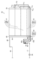
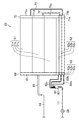
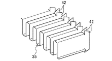
図2および図3に示すように、室外熱交換器(23)は、一つの第1ヘッダ集合管(60)と、一つの第2ヘッダ集合管(70)と、多数の扁平管(33)と、多数のフィン(36)とを備えている。第1ヘッダ集合管(60)、第2ヘッダ集合管(70)、扁平管(33)およびフィン(35)は、何れもアルミニウム合金製の部材であって、互いにロウ付けによって接合されている。
<Configuration of outdoor heat exchanger>
As shown in FIGS. 2 and 3, the outdoor heat exchanger (23) includes one first header collecting pipe (60), one second header collecting pipe (70), and many flat tubes (33). And a large number of fins (36). The first header collecting pipe (60), the second header collecting pipe (70), the flat pipe (33) and the fin (35) are all made of an aluminum alloy and are joined to each other by brazing.
第1ヘッダ集合管(60)と第2ヘッダ集合管(70)は、何れも両端が閉塞された細長い中空円筒状に形成されている。図2および図3では、室外熱交換器(23)の左端に第1ヘッダ集合管(60)が立設され、室外熱交換器(23)の右端に第2ヘッダ集合管(70)が立設されている。つまり、第1ヘッダ集合管(60)と第2ヘッダ集合管(70)は、それぞれの軸方向が上下方向となる状態で設置されている。 Each of the first header collecting pipe (60) and the second header collecting pipe (70) is formed in an elongated hollow cylindrical shape whose both ends are closed. 2 and 3, the first header collecting pipe (60) is erected at the left end of the outdoor heat exchanger (23), and the second header collecting pipe (70) is erected at the right end of the outdoor heat exchanger (23). It is installed. That is, the first header collecting pipe (60) and the second header collecting pipe (70) are installed in a state in which the respective axial directions are vertical.
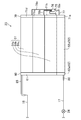
図4にも示すように、扁平管(33)は、その断面形状が扁平な長円形あるいは角の丸い矩形となった伝熱管である。室外熱交換器(23)において、複数の扁平管(33)は、その伸長方向が左右方向となり、それぞれの平坦な側面が対向する状態で配置されている。また、複数の扁平管(33)は、互いに一定の間隔をおいて上下に並んで配置され、それぞれの伸長方向が実質的に平行になっている。図3に示すように、各扁平管(33)は、その一端が第1ヘッダ集合管(60)に挿入され、その他端が第2ヘッダ集合管(70)に挿入されている。 As shown in FIG. 4, the flat tube (33) is a heat transfer tube whose cross-sectional shape is a flat oval or a rounded rectangle. In the outdoor heat exchanger (23), the plurality of flat tubes (33) are arranged in a state in which the extending direction is the left-right direction and the respective flat side surfaces face each other. In addition, the plurality of flat tubes (33) are arranged side by side at regular intervals and their extending directions are substantially parallel to each other. As shown in FIG. 3, each flat tube (33) has one end inserted into the first header collecting tube (60) and the other end inserted into the second header collecting tube (70).
図4に示すように、各扁平管(33)には、複数の流体通路(34)が形成されている。各流体通路(34)は、扁平管(33)の伸長方向に延びる通路である。各扁平管(33)において、複数の流体通路(34)は、扁平管(33)の伸長方向と直交する幅方向に一列に並んでいる。各扁平管(33)に形成された複数の流体通路(34)は、それぞれの一端が第1ヘッダ集合管(60)の内部空間に連通し、それぞれの他端が第2ヘッダ集合管(70)の内部空間に連通している。室外熱交換器(23)へ供給された冷媒は、扁平管(33)の流体通路(34)を流れる間に空気と熱交換する。 As shown in FIG. 4, each flat tube (33) is formed with a plurality of fluid passages (34). Each fluid passage (34) is a passage extending in the extending direction of the flat tube (33). In each flat tube (33), the plurality of fluid passages (34) are arranged in a line in the width direction orthogonal to the extending direction of the flat tube (33). One end of each of the plurality of fluid passages (34) formed in each flat tube (33) communicates with the internal space of the first header collecting pipe (60), and the other end of each of the plurality of fluid passages (34) is the second header collecting pipe (70). ). The refrigerant supplied to the outdoor heat exchanger (23) exchanges heat with air while flowing through the fluid passage (34) of the flat tube (33).
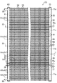
図4に示すように、フィン(36)は、金属板をプレス加工することによって形成された縦長の板状フィンである。フィン(36)には、フィン(36)の前縁(即ち、風上側の縁部)からフィン(36)の幅方向に延びる細長い切欠き部(45)が、多数形成されている。フィン(36)では、多数の切欠き部(45)が、フィン(36)の長手方向(上下方向)に一定の間隔で形成されている。切欠き部(45)の風下寄りの部分は、管挿入部(46)を構成している。管挿入部(46)は、上下方向の幅が扁平管(33)の厚さと実質的に等しく、長さが扁平管(33)の幅と実質的に等しい。扁平管(33)は、フィン(36)の管挿入部(46)に挿入され、管挿入部(46)の周縁部とロウ付けによって接合される。また、フィン(36)には、伝熱を促進するためのルーバー(40)が形成されている。そして、複数のフィン(36)は、扁平管(33)の伸長方向に配列されることで、隣り合う扁平管(33)の間を空気が流れる複数の通風路(38)に区画している。 As shown in FIG. 4, the fin (36) is a vertically long plate-like fin formed by pressing a metal plate. The fin (36) is formed with a number of elongated notches (45) extending in the width direction of the fin (36) from the front edge (ie, the windward edge) of the fin (36). In the fin (36), a large number of notches (45) are formed at regular intervals in the longitudinal direction (vertical direction) of the fin (36). The portion closer to the lee of the notch (45) constitutes the tube insertion portion (46). The tube insertion portion (46) has a vertical width substantially equal to the thickness of the flat tube (33) and a length substantially equal to the width of the flat tube (33). The flat tube (33) is inserted into the tube insertion portion (46) of the fin (36) and joined to the peripheral portion of the tube insertion portion (46) by brazing. Moreover, the louver (40) for promoting heat transfer is formed in the fin (36). The plurality of fins (36) are arranged in the extending direction of the flat tube (33), thereby partitioning between the adjacent flat tubes (33) into a plurality of ventilation paths (38) through which air flows. .
図2に示すように、室外熱交換器(23)の扁平管(33)は、上下に二つの熱交換領域(51,52)に区分されている。つまり、室外熱交換器(23)は、上側熱交換領域(51)と下側熱交換領域(52)が形成されている。そして、各熱交換領域(51,52)は、上下に三つずつの熱交換部(51a〜51c,52a〜52c)に区分されている。具体的に、上側熱交換領域(51)には、下から上に向かって順に、第1主熱交換部(51a)と、第2主熱交換部(51b)と、第3主熱交換部(51c)とが形成されている。下側熱交換領域(52)には、下から上に向かって順に、第1補助熱交換部(52a)と、第2補助熱交換部(52b)と、第3補助熱交換部(52c)とが形成されている。このように、本実施形態の室外熱交換器(23)では、上側熱交換領域(51)および下側熱交換領域(52)において互いに複数且つ同数の熱交換部(51a〜51c,52a〜52c)に区分されている。図3に示すように、各主熱交換部(51a〜51c)は十一本の扁平管(33)を有しており、各補助熱交換部(52a〜52c)は三本の扁平管(33)を有している。なお、各熱交換領域(51,52)に形成される熱交換部(51a〜51c,52a〜52c)の数は、二つであってもよいし、四つ以上であってもよい。 As shown in FIG. 2, the flat tube (33) of the outdoor heat exchanger (23) is vertically divided into two heat exchange regions (51, 52). That is, the outdoor heat exchanger (23) has an upper heat exchange region (51) and a lower heat exchange region (52). Each heat exchanging region (51, 52) is divided into three heat exchanging portions (51a to 51c, 52a to 52c). Specifically, in the upper heat exchange region (51), the first main heat exchange part (51a), the second main heat exchange part (51b), and the third main heat exchange part in order from bottom to top. (51c) is formed. In the lower heat exchange region (52), the first auxiliary heat exchange unit (52a), the second auxiliary heat exchange unit (52b), and the third auxiliary heat exchange unit (52c) are sequentially arranged from the bottom to the top. And are formed. As described above, in the outdoor heat exchanger (23) of the present embodiment, a plurality of and the same number of heat exchange units (51a to 51c, 52a to 52c) in the upper heat exchange region (51) and the lower heat exchange region (52). ). As shown in FIG. 3, each main heat exchange section (51a to 51c) has eleven flat tubes (33), and each auxiliary heat exchange section (52a to 52c) has three flat tubes ( 33). In addition, the number of the heat exchange parts (51a-51c, 52a-52c) formed in each heat exchange area | region (51,52) may be two, and may be four or more.
第1ヘッダ集合管(60)および第2ヘッダ集合管(70)の内部空間は、複数の仕切板(39)によって上下に仕切られている。 The internal spaces of the first header collecting pipe (60) and the second header collecting pipe (70) are divided up and down by a plurality of partition plates (39).
具体的に、第1ヘッダ集合管(60)の内部空間は、上側熱交換領域(51)に対応したガス冷媒の上側空間(61)と、下側熱交換領域(52)に対応した液冷媒の下側空間(62)とに仕切られている。なお、ここで言う液冷媒とは、液単相状態の冷媒または気液二相状態の冷媒を意味する。上側空間(61)は、全ての主熱交換部(51a〜51c)に共通に対応した単一の空間である。つまり、上側空間(61)は、全ての主熱交換部(51a〜51c)の扁平管(33)と連通している。下側空間(62)は、更に仕切板(39)によって、各補助熱交換部(52a〜52c)に対応した該補助熱交換部(52a〜52c)と同数(三つ)の連通空間(62a〜62c)に上下に仕切られている。つまり、下側空間(62)では、第1補助熱交換部(52a)の扁平管(33)と連通する第1連通空間(62a)と、第2補助熱交換部(52b)の扁平管(33)と連通する第2連通空間(62b)と、第3補助熱交換部(52c)の扁平管(33)と連通する第3連通空間(62c)とが形成されている。 Specifically, the internal space of the first header collecting pipe (60) includes a gas refrigerant upper space (61) corresponding to the upper heat exchange region (51) and a liquid refrigerant corresponding to the lower heat exchange region (52). It is partitioned from the lower space (62). The liquid refrigerant referred to here means a liquid single-phase refrigerant or a gas-liquid two-phase refrigerant. The upper space (61) is a single space corresponding to all the main heat exchange sections (51a to 51c). That is, the upper space (61) communicates with the flat tubes (33) of all the main heat exchange parts (51a to 51c). The lower space (62) is further divided by the partition plate (39) into the same number (three) of communication spaces (62a) as the auxiliary heat exchange portions (52a to 52c) corresponding to the auxiliary heat exchange portions (52a to 52c). To 62c). In other words, in the lower space (62), the first communication space (62a) communicating with the flat tube (33) of the first auxiliary heat exchange section (52a) and the flat tube of the second auxiliary heat exchange section (52b) ( A second communication space (62b) that communicates with 33) and a third communication space (62c) that communicates with the flat tube (33) of the third auxiliary heat exchange section (52c) are formed.
第2ヘッダ集合管(70)の内部空間は、上下に五つの連通空間(71a〜71e)に仕切られている。具体的に、第2ヘッダ集合管(70)の内部空間は、上側熱交換領域(51)において最下に位置する第1主熱交換部(51a)と下側熱交換領域(52)において最上に位置する第3補助熱交換部(52c)を除く各主熱交換部(51b,51c)および各補助熱交換部(52a,52b)に対応した四つの連通空間(71a,71b,71d,71e)と、第1主熱交換部(51a)および第3補助熱交換部(52c)に共通に対応した単一の連通空間(71c)とに仕切られている。つまり、第2ヘッダ集合管(70)の内部空間では、第1補助熱交換部(52a)の扁平管(33)と連通する第1連通空間(71a)と、第2補助熱交換部(52b)の扁平管(33)と連通する第2連通空間(71b)と、第3補助熱交換部(52c)および第1主熱交換部(51a)の双方の扁平管(33)と連通する第3連通空間(71c)と、第2主熱交換部(51b)の扁平管(33)と連通する第4連通空間(71d)と、第3主熱交換部(51c)の扁平管(33)と連通する第5連通空間(71e)とが形成されている。 The internal space of the second header collecting pipe (70) is vertically partitioned into five communication spaces (71a to 71e). Specifically, the internal space of the second header collecting pipe (70) is the uppermost in the first main heat exchanging portion (51a) and the lower heat exchanging region (52) located in the lowermost portion in the upper heat exchanging region (51). Four communication spaces (71a, 71b, 71d, 71e) corresponding to the main heat exchange parts (51b, 51c) and the auxiliary heat exchange parts (52a, 52b) except the third auxiliary heat exchange part (52c) located in ) And a single communication space (71c) corresponding to the first main heat exchange part (51a) and the third auxiliary heat exchange part (52c) in common. That is, in the internal space of the second header collecting pipe (70), the first communication space (71a) communicating with the flat pipe (33) of the first auxiliary heat exchange section (52a) and the second auxiliary heat exchange section (52b). ) Communicated with the second communication space (71b) communicating with the flat tube (33) and the flat tubes (33) of both the third auxiliary heat exchange section (52c) and the first main heat exchange section (51a). Three communication spaces (71c), a fourth communication space (71d) communicating with the flat tube (33) of the second main heat exchange section (51b), and a flat tube (33) of the third main heat exchange section (51c) A fifth communication space (71e) that communicates with the first communication space is formed.
第2ヘッダ集合管(70)では、第4連通空間(71d)および第5連通空間(71e)と、第1連通空間(71a)および第2連通空間(71b)とが、各一で対となっている。具体的に、第1連通空間(71a)と第4連通空間(71d)が対となり、第2連通空間(71b)と第5連通空間(71e)が対となっている。そして、第2ヘッダ集合管(70)には、第1連通空間(71a)と第4連通空間(71d)とを接続する第1連通管(72)と、第2連通空間(71b)と第5連通空間(71e)とを接続する第2連通管(73)とが設けられている。つまり、本実施形態の室外熱交換器(23)では、第1主熱交換部(51a)と第3補助熱交換部(52c)が対となり、第2主熱交換部(51b)と第1補助熱交換部(52a)が対となり、第3主熱交換部(51c)と第2補助熱交換部(52b)が対となっている。 In the second header collecting pipe (70), the fourth communication space (71d) and the fifth communication space (71e), and the first communication space (71a) and the second communication space (71b) are in pairs. It has become. Specifically, the first communication space (71a) and the fourth communication space (71d) are paired, and the second communication space (71b) and the fifth communication space (71e) are paired. The second header collecting pipe (70) includes a first communication pipe (72) connecting the first communication space (71a) and the fourth communication space (71d), a second communication space (71b), and a second communication space. A second communication pipe (73) that connects the five communication spaces (71e) is provided. That is, in the outdoor heat exchanger (23) of the present embodiment, the first main heat exchange part (51a) and the third auxiliary heat exchange part (52c) are paired, and the second main heat exchange part (51b) and the first The auxiliary heat exchange part (52a) is paired, and the third main heat exchange part (51c) and the second auxiliary heat exchange part (52b) are paired.
このように、第2ヘッダ集合管(70)の内部空間では、上側熱交換領域(51)の各主熱交換部(51a〜51c)に対応した該主熱交換部(51a〜51c)と同数(三つ)の連通空間(71c,71d,71e)が形成され、且つ、下側熱交換領域(52)の各補助熱交換部(52a〜52c)に対応した該補助熱交換部(52a〜52c)と同数(三つ)の連通空間(71a,71b,71c)が形成されている。そして、上側熱交換領域(51)に対応した連通空間(71c,71d,71e)と下側熱交換領域(52)に対応した連通空間(71a,71b,71c)とが連通している。 Thus, in the internal space of the second header collecting pipe (70), the same number as the main heat exchanging portions (51a to 51c) corresponding to the main heat exchanging portions (51a to 51c) of the upper heat exchanging region (51). (Three) communication spaces (71c, 71d, 71e) are formed, and the auxiliary heat exchange units (52a to 52c) corresponding to the auxiliary heat exchange units (52a to 52c) of the lower heat exchange region (52). The same number (three) of communication spaces (71a, 71b, 71c) as 52c) are formed. The communication spaces (71c, 71d, 71e) corresponding to the upper heat exchange region (51) and the communication spaces (71a, 71b, 71c) corresponding to the lower heat exchange region (52) communicate with each other.
そして、図3に示すように、室外熱交換器(23)では、第2ヘッダ集合管(70)における上側二つの仕切板(39)のそれぞれの側方に位置する部分が、主熱交換部(51a〜51c)同士の境界部(53)となっている。また、室外熱交換器(23)では、第1ヘッダ集合管(60)における下側二つの仕切板(39)と第2ヘッダ集合管(70)における下側二つの仕切板(39)との間の部分が、補助熱交換部(52a〜52c)同士の境界部(54)となっている。また、室外熱交換器(23)では、第1ヘッダ集合管(60)における最上の仕切板(39)の側方に位置する部分が、第1主熱交換部(51a)と第3補助熱交換部(52c)の境界部(55)、即ち上側熱交換領域(51)の熱交換部(51a)と下側熱交換領域(52)の補助熱交換部(52c)の境界部(55)となっている。 And in the outdoor heat exchanger (23), as shown in FIG. 3, the part located in each side of the upper two partition plates (39) in the second header collecting pipe (70) is the main heat exchange section. It is the boundary part (53) between (51a-51c). In the outdoor heat exchanger (23), the lower two partition plates (39) in the first header collecting pipe (60) and the lower two partition plates (39) in the second header collecting pipe (70) The part in between is the boundary part (54) between the auxiliary heat exchange parts (52a to 52c). In the outdoor heat exchanger (23), a portion of the first header collecting pipe (60) located on the side of the uppermost partition plate (39) is connected to the first main heat exchange section (51a) and the third auxiliary heat. The boundary part (55) of the exchange part (52c), that is, the boundary part (55) of the heat exchange part (51a) of the upper heat exchange region (51) and the auxiliary heat exchange part (52c) of the lower heat exchange region (52) It has become.
図2に示すように、室外熱交換器(23)には、液側接続部材(80)とガス側接続部材(85)とが設けられている。液側接続部材(80)およびガス側接続部材(85)は、第1ヘッダ集合管(60)に取り付けられている。 As shown in FIG. 2, the outdoor heat exchanger (23) is provided with a liquid side connection member (80) and a gas side connection member (85). The liquid side connection member (80) and the gas side connection member (85) are attached to the first header collecting pipe (60).
液側接続部材(80)は、一つの分流器(81)と、三本の細径管(82a〜82c)とを備えている。液側接続部材(80)を構成する分流器(81)および細径管(82a〜82c)の材質は、ヘッダ集合管(60,70)や扁平管(33)と同様のアルミニウム合金である。分流器(81)の下端部には、室外熱交換器(23)と膨張弁(24)を繋ぐ銅製の配管(17)が、図外の継手を介して接続されている。分流器(81)の上端部には、各細径管(82a〜82c)の一端が接続されている。分流器(81)の内部では、その下端部に接続された配管と、各細径管(82a〜82c)とが連通している。各細径管(82a〜82c)の他端は、第1ヘッダ集合管(60)の下側空間(62)に接続され、対応する連通空間(62a〜62c)に連通している。各細径管(82a〜82c)は、ロウ付けによって第1ヘッダ集合管(60)と接合されている。 The liquid side connection member (80) includes one shunt (81) and three small diameter tubes (82a to 82c). The material of the flow divider (81) and the small diameter pipes (82a to 82c) constituting the liquid side connection member (80) is the same aluminum alloy as the header collecting pipe (60, 70) and the flat pipe (33). A copper pipe (17) connecting the outdoor heat exchanger (23) and the expansion valve (24) is connected to the lower end of the flow divider (81) via a joint not shown. One end of each small diameter pipe (82a to 82c) is connected to the upper end of the flow divider (81). Inside the flow divider (81), the pipe connected to the lower end thereof communicates with the small diameter pipes (82a to 82c). The other end of each small-diameter pipe (82a to 82c) is connected to the lower space (62) of the first header collecting pipe (60) and communicates with the corresponding communication space (62a to 62c). Each small-diameter pipe (82a to 82c) is joined to the first header collecting pipe (60) by brazing.
図3にも示すように、各細径管(82a〜82c)は、対応する連通空間(62a〜62c)の下端寄りの部分に開口している。つまり、第1細径管(82a)は第1連通空間(62a)の下端寄りの部分に開口し、第2細径管(82b)は第2連通空間(62b)の下端寄りの部分に開口し、第3細径管(82c)は第3連通空間(62c)の下端寄りの部分に開口している。なお、各細径管(82a〜82c)の長さは、各補助熱交換部(52a〜52c)へ流入する冷媒の流量の差がなるべく小さくなるように、個別に設定されている。 As shown also in FIG. 3, each small diameter pipe (82a-82c) is opened in the part near the lower end of corresponding communication space (62a-62c). That is, the first small diameter pipe (82a) opens at a portion near the lower end of the first communication space (62a), and the second small diameter pipe (82b) opens at a portion near the lower end of the second communication space (62b). The third small-diameter pipe (82c) opens at a portion near the lower end of the third communication space (62c). In addition, the length of each small diameter pipe | tube (82a-82c) is set individually so that the difference in the flow volume of the refrigerant | coolant which flows into each auxiliary heat exchange part (52a-52c) may become as small as possible.
ガス側接続部材(85)は、比較的大径の一つの配管で構成されている。ガス側接続部材(85)の材質は、ヘッダ集合管(60,70)や扁平管(33)と同様のアルミニウム合金である。ガス側接続部材(85)の一端は、室外熱交換器(23)と四方切換弁(22)の第3のポートを繋ぐ銅製の配管(18)が、図外の継手を介して接続されている。ガス側接続部材(85)の他端は、第1ヘッダ集合管(60)における上側空間(61)の上端寄りの部分に開口している。ガス側接続部材(85)は、ロウ付けによって第1ヘッダ集合管(60)と接合されている。 The gas side connection member (85) is comprised by one piping with a comparatively large diameter. The material of the gas side connection member (85) is the same aluminum alloy as the header collecting pipe (60, 70) and the flat pipe (33). One end of the gas side connection member (85) is connected to a copper pipe (18) connecting the outdoor heat exchanger (23) and the third port of the four-way switching valve (22) via a joint not shown. Yes. The other end of the gas side connection member (85) opens in a portion near the upper end of the upper space (61) in the first header collecting pipe (60). The gas side connection member (85) is joined to the first header collecting pipe (60) by brazing.
〈室外熱交換器における冷媒の流れ〉
空気調和機(10)の冷房運転中には、室外熱交換器(23)が凝縮器として機能する。冷房運転中における室外熱交換器(23)での冷媒の流れを説明する。
<Flow of refrigerant in outdoor heat exchanger>
During the cooling operation of the air conditioner (10), the outdoor heat exchanger (23) functions as a condenser. The flow of the refrigerant in the outdoor heat exchanger (23) during the cooling operation will be described.
室外熱交換器(23)には、圧縮機(21)から吐出されたガス冷媒が供給される。圧縮機(21)から送られたガス冷媒は、ガス側接続部材(85)を介して第1ヘッダ集合管(60)の上側空間(61)へ流入した後、各主熱交換部(51a〜51c)の各扁平管(33)へ分配される。各扁平管(33)の流体通路(34)へ流入した冷媒は、流体通路(34)を流れる間に室外空気へ放熱して凝縮し、その後に第2ヘッダ集合管(70)の対応する各連通空間(71c,71d,71e)へ流入する。 Gas refrigerant discharged from the compressor (21) is supplied to the outdoor heat exchanger (23). After the gas refrigerant sent from the compressor (21) flows into the upper space (61) of the first header collecting pipe (60) via the gas side connection member (85), each main heat exchange section (51a- 51c) is distributed to each flat tube (33). The refrigerant flowing into the fluid passage (34) of each flat tube (33) dissipates heat and condenses to the outdoor air while flowing through the fluid passage (34), and then the corresponding each of the second header collecting pipe (70). It flows into the communication space (71c, 71d, 71e).
第2ヘッダ集合管(70)において、第3連通空間(71c)へ流入した冷媒はそのまま第3補助熱交換部(52c)の各扁平管(33)へ分配され、第4連通空間(71d)へ流入した冷媒は第1連通管(72)を介して第1連通空間(71a)へ流入し第1補助熱交換部(52a)の各扁平管(33)へ分配され、第5連通空間(71e)へ流入した冷媒は第2連通管(73)を介して第2連通空間(71b)へ流入し第2補助熱交換部(52b)の各扁平管(33)へ分配される。各補助熱交換部(52a〜52c)における各扁平管(33)の流体通路(34)へ流入した冷媒は、流体通路(34)を流れる間に室外空気へ放熱し、過冷却液状態となって第1ヘッダ集合管(60)における下側空間(62)の対応する連通空間(62a〜62c)へ流入する。 In the second header collecting pipe (70), the refrigerant flowing into the third communication space (71c) is distributed as it is to each flat pipe (33) of the third auxiliary heat exchange section (52c), and the fourth communication space (71d) The refrigerant that has flowed into the first communication pipe (72) flows into the first communication space (71a), is distributed to the flat tubes (33) of the first auxiliary heat exchange section (52a), and the fifth communication space ( The refrigerant flowing into 71e) flows into the second communication space (71b) via the second communication pipe (73) and is distributed to the flat tubes (33) of the second auxiliary heat exchange section (52b). The refrigerant that has flowed into the fluid passage (34) of each flat tube (33) in each auxiliary heat exchange section (52a to 52c) dissipates heat to the outdoor air while flowing through the fluid passage (34), and enters a supercooled liquid state. Flow into the corresponding communication spaces (62a to 62c) of the lower space (62) in the first header collecting pipe (60).
第1ヘッダ集合管(60)における下側空間(62)の各連通空間(62a〜62c)へ流入した冷媒は、液側接続部材(80)の細径管(82a〜82c)を通って分流器(81)へ流入する。分流器(81)では、各細径管(82a〜82c)から流入した冷媒が合流する。分流器(81)において合流した冷媒は、室外熱交換器(23)から膨張弁(24)へ向かって流出してゆく。このように、冷房運転時の室外熱交換器(23)では、冷媒が上側熱交換領域(51)の各主熱交換部(51a〜51c)へ流入して放熱した後、下側熱交換領域(52)の各補助熱交換部(52a〜52c)へ流入して更に放熱する。 The refrigerant flowing into the communication spaces (62a to 62c) of the lower space (62) in the first header collecting pipe (60) is diverted through the small diameter pipes (82a to 82c) of the liquid side connection member (80). Flow into the vessel (81). In the flow divider (81), the refrigerant flowing in from the small diameter tubes (82a to 82c) joins. The refrigerant merged in the flow divider (81) flows out from the outdoor heat exchanger (23) toward the expansion valve (24). Thus, in the outdoor heat exchanger (23) during the cooling operation, the refrigerant flows into the main heat exchange portions (51a to 51c) of the upper heat exchange region (51) to dissipate heat, and then the lower heat exchange region. It flows into each auxiliary heat exchange part (52a-52c) of (52), and further radiates heat.
空気調和機(10)の暖房運転中には、室外熱交換器(23)が蒸発器として機能する。暖房運転中における室外熱交換器(23)での冷媒の流れを説明する。 During the heating operation of the air conditioner (10), the outdoor heat exchanger (23) functions as an evaporator. The flow of the refrigerant in the outdoor heat exchanger (23) during the heating operation will be described.
室外熱交換器(23)には、膨張弁(24)を通過する際に膨張して気液二相状態となった冷媒が供給される。膨張弁(24)から送られた冷媒は、液側接続部材(80)の分流器(81)へ流入した後に三本の細径管(82a〜82c)へ分かれて流入し、第1ヘッダ集合管(60)における下側空間(62)の各連通空間(62a〜62c)へ分配される。 The outdoor heat exchanger (23) is supplied with the refrigerant that has expanded into a gas-liquid two-phase state when passing through the expansion valve (24). The refrigerant sent from the expansion valve (24) flows into the three small diameter pipes (82a to 82c) after flowing into the flow divider (81) of the liquid side connecting member (80), and the first header set It distributes to each communication space (62a-62c) of the lower space (62) in the pipe (60).
第1ヘッダ集合管(60)における下側空間(62)の連通空間(62a〜62c)へ流入した冷媒は、対応する各補助熱交換部(52a〜52c)の各扁平管(33)へ分配される。各扁平管(33)の流体通路(34)へ流入した冷媒は、流体通路(34)を流れて第2ヘッダ集合管(70)の対応する連通空間(71a,71b,71c)へ流入する。この連通空間(71a,71b,71c)へ流入した冷媒は、依然として気液二相状態のままである。 The refrigerant that has flowed into the communication spaces (62a to 62c) of the lower space (62) in the first header collecting pipe (60) is distributed to the flat tubes (33) of the corresponding auxiliary heat exchange sections (52a to 52c). Is done. The refrigerant flowing into the fluid passage (34) of each flat tube (33) flows through the fluid passage (34) and into the corresponding communication space (71a, 71b, 71c) of the second header collecting pipe (70). The refrigerant that has flowed into the communication space (71a, 71b, 71c) still remains in a gas-liquid two-phase state.
第2ヘッダ集合管(70)において、第1連通空間(71a)へ流入した冷媒は第1連通管(72)を介して第4連通空間(71d)へ流入し第2主熱交換部(51b)の各扁平管(33)へ分配され、第2連通空間(71b)へ流入した冷媒は第2連通管(73)を介して第5連通空間(71e)へ流入し第3主熱交換部(51c)の各扁平管(33)へ分配され、第3連通空間(71c)へ流入した冷媒はそのまま第1主熱交換部(51a)の各扁平管(33)へ分配される。各主熱交換部(51a〜51c)における各扁平管(33)の流体通路(34)へ流入した冷媒は、流体通路(34)を流れる間に室外空気から吸熱して蒸発し、ほぼガス単相状態となって第1ヘッダ集合管(60)の上側空間(61)で合流する。第1ヘッダ集合管(60)の上側空間(61)で合流した冷媒は、ガス側接続部材(85)から圧縮機(21)へ向かって流出してゆく。このように、暖房運転時の室外熱交換器(23)では、冷媒が下側熱交換領域(52)の各補助熱交換部(52a〜52c)へ流入した後、上側熱交換領域(51)の各主熱交換部(51a〜51c)へ流入して吸熱する。 In the second header collecting pipe (70), the refrigerant flowing into the first communication space (71a) flows into the fourth communication space (71d) via the first communication pipe (72) and enters the second main heat exchange section (51b). The refrigerant that has been distributed to the flat tubes (33) and flowed into the second communication space (71b) flows into the fifth communication space (71e) via the second communication tube (73), and is the third main heat exchange section. The refrigerant that is distributed to the flat tubes (33) of (51c) and flows into the third communication space (71c) is distributed as it is to the flat tubes (33) of the first main heat exchange section (51a). The refrigerant that has flowed into the fluid passage (34) of each flat tube (33) in each main heat exchange section (51a to 51c) absorbs heat from the outdoor air while flowing through the fluid passage (34), evaporates, and is almost gas alone. They are in phase and merge in the upper space (61) of the first header collecting pipe (60). The refrigerant joined in the upper space (61) of the first header collecting pipe (60) flows out from the gas side connecting member (85) toward the compressor (21). Thus, in the outdoor heat exchanger (23) during the heating operation, after the refrigerant flows into each auxiliary heat exchange section (52a to 52c) of the lower heat exchange region (52), the upper heat exchange region (51) It flows into each main heat exchange part (51a-51c) and absorbs heat.
−実施形態1の効果−
本実施形態の室外熱交換器(23)は、順に冷媒が流通する主熱交換部(51a〜51c)および補助熱交換部(52a〜52c)の対を複数有し、複数の主熱交換部(51a〜51c)が上下に並ぶ上側熱交換領域(51)と、複数の補助熱交換部(52a〜52c)が上下に並ぶ下側熱交換領域(52)とに区分されている。つまり、本実施形態の室外熱交換器(23)では、複数の主熱交換部(51a〜51c)が上下方向における片側(上側)へ集合して配列され、複数の補助熱交換部(52a〜52c)が反対側の片側(下側)へ集合して配列されている。これにより、主熱交換部と補助熱交換部が互いに隣接する箇所を最少の1箇所に抑えることができる。つまり、本実施形態の室外熱交換器(23)において、主熱交換部(51a〜51c)と補助熱交換部(52a〜52c)とが隣接する箇所は、上側熱交換領域(51)において最下に位置する第1主熱交換部(51a)と下側熱交換領域(52)において最上に位置する第3補助熱交換部(52c)とが隣接する箇所のみである。
-Effect of Embodiment 1-
The outdoor heat exchanger (23) of the present embodiment has a plurality of pairs of main heat exchanging parts (51a to 51c) and auxiliary heat exchanging parts (52a to 52c) through which the refrigerant flows in order, and a plurality of main heat exchanging parts The upper heat exchange region (51) in which (51a to 51c) is arranged vertically is divided into the lower heat exchange region (52) in which the plurality of auxiliary heat exchange parts (52a to 52c) are arranged vertically. That is, in the outdoor heat exchanger (23) of the present embodiment, the plurality of main heat exchange units (51a to 51c) are gathered and arranged on one side (upper side) in the vertical direction, and the plurality of auxiliary heat exchange units (52a to 52c) are arranged. 52c) are gathered and arranged on one side (lower side) of the opposite side. Thereby, the location where the main heat exchange part and the auxiliary heat exchange part are adjacent to each other can be suppressed to a minimum of one place. That is, in the outdoor heat exchanger (23) of the present embodiment, the location where the main heat exchange part (51a to 51c) and the auxiliary heat exchange part (52a to 52c) are adjacent is the highest in the upper heat exchange region (51). It is only a location where the first main heat exchange part (51a) located below and the third auxiliary heat exchange part (52c) located at the top in the lower heat exchange region (52) are adjacent to each other.
主熱交換部(51a〜51c)を流通する冷媒の温度と、補助熱交換部(52a〜52c)を流通する冷媒の温度とは異なる。具体的に、主熱交換部(51a〜51c)を流通する冷媒の温度は、補助熱交換部(52a〜52c)を流通する冷媒の温度よりも高い。そのため、互いに隣接する主熱交換部の扁平管(33)と補助熱交換部の扁平管(33)との間では、その隣接間のフィン(36)を通じて互いの冷媒同士が熱交換してしまい、その分冷媒と空気との間で交換する熱量が減少する。いわゆる熱ロスが生じる。その結果、室外熱交換器(23)の熱交換効率が低下してしまう。このような冷媒の熱ロスは、主熱交換部と補助熱交換部が互いに隣接する箇所が多いほど増大する。そのため、主熱交換部と補助熱交換部が互いに隣接する箇所が少ないほど、熱交換効率の低下を抑制することができる。ここで、例えば、互いに複数且つ同数の主熱交換部および補助熱交換部を有する熱交換器において、一つの主熱交換部および一つの補助熱交換部を対として互いに隣接させ、その隣接した対を上下に複数連ねた場合、主熱交換部と補助熱交換部が互いに隣接する箇所は、主熱交換部および補助熱交換部の合計数の一つだけ少ない数の箇所となる。これに対し、本実施形態の室外熱交換器(23)によれば、主熱交換部(51a〜51c)と補助熱交換部(52a〜52c)との隣接箇所が最少の1箇所になるため、冷媒の熱ロスを最大限に抑制でき熱交換効率の低下を大幅に抑制することができる。 The temperature of the refrigerant flowing through the main heat exchange unit (51a to 51c) is different from the temperature of the refrigerant flowing through the auxiliary heat exchange unit (52a to 52c). Specifically, the temperature of the refrigerant flowing through the main heat exchange unit (51a to 51c) is higher than the temperature of the refrigerant flowing through the auxiliary heat exchange unit (52a to 52c). For this reason, between the flat tubes (33) of the main heat exchanger adjacent to each other and the flat tubes (33) of the auxiliary heat exchanger, the refrigerants exchange heat with each other through the fins (36) between the adjacent tubes. Accordingly, the amount of heat exchanged between the refrigerant and the air decreases. So-called heat loss occurs. As a result, the heat exchange efficiency of the outdoor heat exchanger (23) decreases. The heat loss of such a refrigerant increases as the number of places where the main heat exchange part and the auxiliary heat exchange part are adjacent to each other increases. Therefore, a decrease in heat exchange efficiency can be suppressed as the number of places where the main heat exchange unit and the auxiliary heat exchange unit are adjacent to each other is small. Here, for example, in a heat exchanger having a plurality of and the same number of main heat exchange units and auxiliary heat exchange units, one main heat exchange unit and one auxiliary heat exchange unit are adjacent to each other as a pair, and the adjacent pairs When a plurality of the main heat exchange units and the auxiliary heat exchange units are adjacent to each other, the number of locations where the main heat exchange unit and the auxiliary heat exchange unit are adjacent to each other is one less than the total number of main heat exchange units and auxiliary heat exchange units. On the other hand, according to the outdoor heat exchanger (23) of the present embodiment, the adjacent portion between the main heat exchange part (51a to 51c) and the auxiliary heat exchange part (52a to 52c) is the smallest one place. Thus, the heat loss of the refrigerant can be suppressed to the maximum, and the decrease in heat exchange efficiency can be significantly suppressed.
一般に、本実施形態の熱交換器(23,25)のような空気熱交換器では、中央ほど風速が高い。ここで、上述したような互いに隣接した主熱交換部と補助熱交換部の対を上下に複数連ねた熱交換器の場合、風速の高い範囲に補助熱交換部も配置されることになり、その分、風速の高い範囲に配置される主熱交換部の面積が少なくなる。これにより、主熱交換部は補助熱交換部よりも空気の熱量を多く必要とするところ、主熱交換部の能力が充分に発揮されなくなる。これに対し、本実施形態の室外熱交換器(23)によれば、上述したように複数の主熱交換部(51a〜51c)および補助熱交換部(52a〜52c)をそれぞれ片側に集合させることで、風速の低い範囲に補助熱交換部(52a〜52c)を配置し風速の高い範囲に主熱交換部(51a〜51c)を配置することができる。よって、主熱交換部(51a〜51c)における熱交換能力を充分に発揮させることができる。 Generally, in an air heat exchanger such as the heat exchanger (23, 25) of the present embodiment, the wind speed is higher at the center. Here, in the case of a heat exchanger in which a plurality of pairs of the main heat exchange part and the auxiliary heat exchange part adjacent to each other as described above are connected vertically, the auxiliary heat exchange part is also arranged in a high wind speed range, Accordingly, the area of the main heat exchanging portion arranged in the high wind speed range is reduced. As a result, the main heat exchanging part requires a larger amount of heat of air than the auxiliary heat exchanging part, but the ability of the main heat exchanging part is not sufficiently exhibited. On the other hand, according to the outdoor heat exchanger (23) of the present embodiment, as described above, the plurality of main heat exchange units (51a to 51c) and the auxiliary heat exchange units (52a to 52c) are assembled on one side, respectively. Thus, the auxiliary heat exchange unit (52a to 52c) can be arranged in a range where the wind speed is low, and the main heat exchange unit (51a to 51c) can be arranged in a range where the wind speed is high. Therefore, the heat exchange capability in the main heat exchange part (51a-51c) can fully be exhibited.
また、本実施形態の室外熱交換器(23)では、液側接続部材(80)とガス側接続部材(85)の両方が第1ヘッダ集合管(60)に取り付けられる。つまり、本実施形態の室外熱交換器(23)では、複数の熱交換部(51a〜51c,52a〜52c)に対して冷媒を流入出させるための部材が、第1ヘッダ集合管(60)に取り付けられる。したがって、本実施形態によれば、膨張弁(24)や四方切換弁(22)から延びる配管(17,18)の室外熱交換器(23)に対する接続位置を近接させることができ、室外熱交換器(23)の設置作業を簡素化することができる。 In the outdoor heat exchanger (23) of the present embodiment, both the liquid side connection member (80) and the gas side connection member (85) are attached to the first header collecting pipe (60). That is, in the outdoor heat exchanger (23) of the present embodiment, the member for allowing the refrigerant to flow into and out of the plurality of heat exchange parts (51a to 51c, 52a to 52c) is the first header collecting pipe (60). Attached to. Therefore, according to the present embodiment, the connection positions of the pipes (17, 18) extending from the expansion valve (24) and the four-way switching valve (22) to the outdoor heat exchanger (23) can be brought close to each other, and the outdoor heat exchange is performed. The installation work of the vessel (23) can be simplified.
また、本実施形態の室外熱交換器(23)の第1ヘッダ集合管(60)では、下側空間(62)における各連通空間(62a〜62c)の下端寄りの位置に液側接続部材(80)の細径管(82a〜82c)が連通している。したがって、本実施形態の室外熱交換器(23)が凝縮器として機能する場合は、密度の大きい液冷媒を連通空間(62a〜62c)から液側接続部材(80)の細径管(82a〜82c)へ確実に送り込むことができる。更に、本実施形態の室外熱交換器(23)の第1ヘッダ集合管(60)では、上側空間(61)の上端寄りの位置にガス側接続部材(85)が連通している。したがって、本実施形態の室外熱交換器(23)が蒸発器として機能する場合は、密度の小さいガス冷媒を上側空間(61)からガス側接続部材(85)へ確実に送り込むことができる。 Further, in the first header collecting pipe (60) of the outdoor heat exchanger (23) of the present embodiment, the liquid side connecting member (at the position near the lower end of each communication space (62a to 62c) in the lower space (62). 80) small diameter pipes (82a to 82c) communicate with each other. Therefore, when the outdoor heat exchanger (23) of the present embodiment functions as a condenser, liquid refrigerant having a high density is passed from the communication space (62a to 62c) to the small diameter pipe (82a to 82a to the liquid side connection member (80)). 82c). Further, in the first header collecting pipe (60) of the outdoor heat exchanger (23) of the present embodiment, the gas side connecting member (85) communicates with a position near the upper end of the upper space (61). Therefore, when the outdoor heat exchanger (23) of this embodiment functions as an evaporator, a low-density gas refrigerant can be reliably sent from the upper space (61) to the gas-side connection member (85).
−実施形態1の変形例1−
実施形態1の室外熱交換器(23)では、図5に破線で示す位置に扁平管(33)を設けないようにしてもよい。具体的に、図5に示す本変形例1の室外熱交換器(23)では、互いに隣接する第1主熱交換部(51a)および第3補助熱交換部(52c)において第1主熱交換部(51a)の最下に位置する扁平管(33)が省略されている。つまり、第1主熱交換部(51a)において第3補助熱交換部(52c)の扁平管(33)に最も近い扁平管(33)が省略されている。
-
In the outdoor heat exchanger (23) of the first embodiment, the flat tube (33) may not be provided at the position indicated by the broken line in FIG. Specifically, in the outdoor heat exchanger (23) of the first modification shown in FIG. 5, the first main heat exchange is performed in the first main heat exchange section (51a) and the third auxiliary heat exchange section (52c) adjacent to each other. The flat tube (33) located at the bottom of the part (51a) is omitted. That is, the flat tube (33) closest to the flat tube (33) of the third auxiliary heat exchange unit (52c) is omitted in the first main heat exchange unit (51a).
本変形例の室外熱交換器(23)では、第1主熱交換部(51a)と第3補助熱交換部(52c)の境界部(55)を挟んで上下に隣り合う扁平管(33)の間に形成された扁平管(33)の設けられない部分が、伝熱抑制構造(57)を構成している。 In the outdoor heat exchanger (23) of the present modification, flat tubes (33) that are adjacent to each other across the boundary (55) between the first main heat exchange part (51a) and the third auxiliary heat exchange part (52c). The portion where the flat tube (33) formed between the portions is not provided constitutes the heat transfer suppression structure (57).
この構成によれば、第1主熱交換部(51a)の最下に位置する扁平管(33)と第3補助熱交換部(52c)の最上に位置する扁平管(33)との間隔D2が、他の扁平管(33)同士の間隔D1よりも広くなる。これにより、互いに隣り合う第1主熱交換部(51a)の扁平管(33)と第3補助熱交換部(52c)の扁平管(33)との間における熱の移動を抑制することができる。つまり、隣り合う扁平管(33)同士の間で行われる冷媒同士の熱交換の量(熱ロス)を一層削減することができる。その結果、室外熱交換器(23)の熱交換効率の低下をより一層抑制することができる。 According to this configuration, the distance D2 between the flat tube (33) located at the bottom of the first main heat exchange part (51a) and the flat tube (33) located at the top of the third auxiliary heat exchange part (52c). However, it becomes wider than the interval D1 between the other flat tubes (33). Thereby, the movement of the heat between the flat tube (33) of the 1st main heat exchange part (51a) adjacent to each other and the flat tube (33) of the 3rd auxiliary heat exchange part (52c) can be controlled. . That is, the amount of heat exchange (heat loss) between the refrigerants performed between the adjacent flat tubes (33) can be further reduced. As a result, it is possible to further suppress a decrease in the heat exchange efficiency of the outdoor heat exchanger (23).
なお、本変形例では、第1主熱交換部(51a)の最下に位置する扁平管(33)に代えて、第3補助熱交換部(52c)の最上に位置する扁平管(33)を省略するようにしてもよいし、第1主熱交換部(51a)の最下に位置する扁平管(33)と第3補助熱交換部(52c)の最上に位置する扁平管(33)の両方を省略するようにしてもよい。 In this modification, instead of the flat tube (33) located at the bottom of the first main heat exchange part (51a), the flat tube (33) located at the top of the third auxiliary heat exchange part (52c) May be omitted, or the flat tube (33) located at the bottom of the first main heat exchange part (51a) and the flat tube (33) located at the top of the third auxiliary heat exchange part (52c) Both of these may be omitted.
−実施形態1の変形例2−
実施形態1の室外熱交換器(23)では、図6に示すように、黒く塗りつぶされた扁平管(33a)に冷媒を実質的に流通させないようにしてもよい。具体的に、本変形例2の室外熱交換器(23)における第1ヘッダ集合管(60)では、第1主熱交換部(51a)の最下に位置する扁平管(33a)の上下に仕切板(39)が設置されている。このため、本変形例の室外熱交換器(23)において、上記の扁平管(33a)は実質的に冷媒が通過しない封止された状態となる。
-Modification 2 of
In the outdoor heat exchanger (23) of the first embodiment, as shown in FIG. 6, the refrigerant may not be substantially circulated through the flat tube (33a) painted black. Specifically, in the first header collecting pipe (60) in the outdoor heat exchanger (23) of the second modification example, the flat pipe (33a) located at the bottom of the first main heat exchange section (51a) is located above and below. A partition plate (39) is installed. For this reason, in the outdoor heat exchanger (23) of this modification, said flat tube (33a) will be in the sealed state which a refrigerant | coolant does not pass substantially.
つまり、本変形例の室外熱交換器(23)では、上記扁平管(33a)の上下に設置された仕切板(39)の間に位置する部分が、上側熱交換領域(51)の第1主熱交換部(51a)と下側熱交換領域(52)の第3補助熱交換部(52c)との境界部(55)となっている。この境界部(55)には、実質的に封止された上記扁平管(33a)が存在している。そして、本変形例の室外熱交換器(23)では、実質的に封止された扁平管(33a)が伝熱抑制構造(57)を構成している。 That is, in the outdoor heat exchanger (23) of this modification, the portion located between the partition plates (39) installed above and below the flat tube (33a) is the first heat exchange region (51). It is a boundary part (55) between the main heat exchange part (51a) and the third auxiliary heat exchange part (52c) of the lower heat exchange region (52). In the boundary portion (55), the flat tube (33a) substantially sealed is present. And in the outdoor heat exchanger (23) of this modification, the substantially sealed flat tube (33a) comprises the heat-transfer suppression structure (57).
この構成によれば、第1主熱交換部(51a)において冷媒が実質的に流通する扁平管(33)のうち最下に位置する扁平管(33)と第3補助熱交換部(52c)の最上に位置する扁平管(33)との間隔D2が、他の扁平管(33)同士の間隔D1よりも広くなる。これにより、互いに隣接する第1主熱交換部(51a)の扁平管(33)と第3補助熱交換部(52c)の扁平管(33)との間における熱の移動を抑制することができる。つまり、隣り合う扁平管(33)同士の間で行われる冷媒同士の熱交換の量(熱ロス)を一層削減することができる。その結果、室外熱交換器(23)の熱交換効率の低下をより一層抑制することができる。 According to this configuration, the flat tube (33) positioned at the bottom of the flat tube (33) through which the refrigerant substantially circulates in the first main heat exchange unit (51a) and the third auxiliary heat exchange unit (52c). The distance D2 between the flat tube (33) located at the top of the tube is wider than the distance D1 between the other flat tubes (33). Thereby, the movement of the heat between the flat tube (33) of the 1st main heat exchange part (51a) adjacent to each other and the flat tube (33) of the 3rd auxiliary heat exchange part (52c) can be controlled. . That is, the amount of heat exchange (heat loss) between the refrigerants performed between the adjacent flat tubes (33) can be further reduced. As a result, it is possible to further suppress a decrease in the heat exchange efficiency of the outdoor heat exchanger (23).
なお、本変形例の第1ヘッダ集合管(60)では、第1主熱交換部(51a)の最下に位置する扁平管(33a)に代えて、第3補助熱交換部(52c)の最上に位置する扁平管(33)のすぐ上とすぐ下の両方に仕切板(39)を設置するようにしてもよいし、第1主熱交換部(51a)の最下に位置する扁平管(33a)と第3補助熱交換部(52c)の最上に位置する扁平管(33)のそれぞれのすぐ上とすぐ下の両方に仕切板(39)を設置するようにしてもよい。 In the first header collecting pipe (60) of this modification, instead of the flat pipe (33a) positioned at the bottom of the first main heat exchange part (51a), the third auxiliary heat exchange part (52c) A partition plate (39) may be installed both directly above and below the flat tube (33) positioned at the top, or the flat tube positioned at the bottom of the first main heat exchange section (51a). (33a) and the partition plate (39) may be installed both directly above and immediately below each of the flat tubes (33) positioned at the top of the third auxiliary heat exchanger (52c).
《発明の実施形態2》
本発明の実施形態2について説明する。本実施形態は、上記実施形態1の室外熱交換器(23)の構成を変更したものである。ここでは、本実施形態の室外熱交換器(23)について、図7および図8を適宜参照しながら、上記実施形態1と異なる点を説明する。
<< Embodiment 2 of the Invention >>
A second embodiment of the present invention will be described. In the present embodiment, the configuration of the outdoor heat exchanger (23) of the first embodiment is changed. Here, about the outdoor heat exchanger (23) of this embodiment, a different point from the said
図7に示すように、室外熱交換器(23)の扁平管(33)は、上記実施形態1と同様、上下に上側熱交換領域(51)と下側熱交換領域(52)とに区分されている。そして、上側熱交換領域(51)は上下に並ぶ三つの主熱交換部(51a〜51c)に区分され、下側熱交換領域(52)は一つの補助熱交換部(52a)で構成されている。つまり、上側熱交換領域(51)には、下から上に向かって順に、第1主熱交換部(51a)と、第2主熱交換部(51b)と、第3主熱交換部(51c)とが形成されている。図8に示すように、各主熱交換部(51a〜51c)は十一本の扁平管(33)を有しており、補助熱交換部(52a)は九本の扁平管(33)を有している。なお、上側熱交換領域(51)に形成される主熱交換部(51a〜51c)の数は、二つであってもよいし、四つ以上であってもよい。 As shown in FIG. 7, the flat tube (33) of the outdoor heat exchanger (23) is divided into an upper heat exchange region (51) and a lower heat exchange region (52) in the vertical direction, as in the first embodiment. Has been. The upper heat exchange area (51) is divided into three main heat exchange sections (51a to 51c) arranged vertically, and the lower heat exchange area (52) is composed of one auxiliary heat exchange section (52a). Yes. That is, in the upper heat exchange region (51), the first main heat exchange unit (51a), the second main heat exchange unit (51b), and the third main heat exchange unit (51c) are sequentially arranged from the bottom to the top. ) And are formed. As shown in FIG. 8, each main heat exchange part (51a-51c) has eleven flat tubes (33), and the auxiliary heat exchange part (52a) has nine flat tubes (33). Have. Note that the number of main heat exchange portions (51a to 51c) formed in the upper heat exchange region (51) may be two, or may be four or more.
第1ヘッダ集合管(60)および第2ヘッダ集合管(70)の内部空間は、仕切板(39)によって上下に仕切られている。 The internal spaces of the first header collecting pipe (60) and the second header collecting pipe (70) are divided up and down by a partition plate (39).
具体的に、第1ヘッダ集合管(60)の内部空間は、上側熱交換領域(51)に対応したガス冷媒の上側空間(61)と、下側熱交換領域(52)に対応した液冷媒の下側空間(62)(連通空間(62a))とに仕切られている。なお、ここで言う液冷媒とは、上記実施形態1と同様、液単相状態の冷媒または気液二相状態の冷媒を意味する。上側空間(61)は、全ての主熱交換部(51a〜51c)に共通に対応した単一の空間である。つまり、上側空間(61)は、全ての主熱交換部(51a〜51c)の扁平管(33)と連通している。下側空間(62)(連通空間(62a))は、一つの補助熱交換部(52a)に対応した単一の空間であり、補助熱交換部(52a)の扁平管(33)と連通している。 Specifically, the internal space of the first header collecting pipe (60) includes a gas refrigerant upper space (61) corresponding to the upper heat exchange region (51) and a liquid refrigerant corresponding to the lower heat exchange region (52). And a lower space (62) (communication space (62a)). The liquid refrigerant referred to here means a liquid single-phase refrigerant or a gas-liquid two-phase refrigerant as in the first embodiment. The upper space (61) is a single space corresponding to all the main heat exchange sections (51a to 51c). That is, the upper space (61) communicates with the flat tubes (33) of all the main heat exchange parts (51a to 51c). The lower space (62) (communication space (62a)) is a single space corresponding to one auxiliary heat exchange part (52a), and communicates with the flat tube (33) of the auxiliary heat exchange part (52a). ing.
第2ヘッダ集合管(70)の内部空間は、上下に四つの連通空間(71a〜71d)に仕切られている。具体的に、第2ヘッダ集合管(70)の内部空間は、上側熱交換領域(51)の各主熱交換部(51a〜51c)に対応した三つの連通空間(71b,71c,71d)と、下側熱交換領域(52)の補助熱交換部(52a)に対応した一つの連通空間(71a)とに仕切られている。つまり、第2ヘッダ集合管(70)の内部空間では、補助熱交換部(52a)の扁平管(33)と連通する第1連通空間(71a)と、第1主熱交換部(51a)の扁平管(33)と連通する第2連通空間(71b)と、第2主熱交換部(51b)の扁平管(33)と連通する第3連通空間(71c)と、第3主熱交換部(51c)の扁平管(33)と連通する第4連通空間(71d)とが形成されている。 The internal space of the second header collecting pipe (70) is vertically partitioned into four communication spaces (71a to 71d). Specifically, the internal space of the second header collecting pipe (70) includes three communication spaces (71b, 71c, 71d) corresponding to the main heat exchange portions (51a to 51c) of the upper heat exchange region (51). , And is divided into one communication space (71a) corresponding to the auxiliary heat exchange section (52a) of the lower heat exchange region (52). That is, in the internal space of the second header collecting pipe (70), the first communication space (71a) communicating with the flat pipe (33) of the auxiliary heat exchange section (52a) and the first main heat exchange section (51a). A second communication space (71b) communicating with the flat tube (33), a third communication space (71c) communicating with the flat tube (33) of the second main heat exchange section (51b), and a third main heat exchange section A fourth communication space (71d) communicating with the flat tube (33) of (51c) is formed.
第2ヘッダ集合管(70)には、連通部材(75)が設けられている。連通部材(75)は、一つの分流器(76)と、一本の主管(77)と、三本の細径管(78a〜78c)とを備えている。主管(77)の一端は分流器(76)の下端部に接続され、他端は第2ヘッダ集合管(70)の第1連通空間(71a)に接続されている。分流器(76)の上端部には、各細径管(78a〜78c)の一端が接続されている。分流器(81)の内部では、主管(77)と各細径管(78a〜78c)とが連通している。各細径管(78a〜78c)の他端は、第2ヘッダ集合管(70)の対応する第2〜第4連通空間(71b〜71d)に連通している。 A communication member (75) is provided in the second header collecting pipe (70). The communication member (75) includes one shunt (76), one main pipe (77), and three small diameter pipes (78a to 78c). One end of the main pipe (77) is connected to the lower end of the flow divider (76), and the other end is connected to the first communication space (71a) of the second header collecting pipe (70). One end of each small-diameter pipe (78a to 78c) is connected to the upper end of the flow divider (76). Inside the flow divider (81), the main pipe (77) and the small diameter pipes (78a to 78c) communicate with each other. The other ends of the small diameter pipes (78a to 78c) communicate with the corresponding second to fourth communication spaces (71b to 71d) of the second header collecting pipe (70).
図8にも示すように、各細径管(78a〜78c)は、対応する第2〜第4連通空間(71b〜71d)の下端寄りの部分に開口している。つまり、第1細径管(78a)は第2連通空間(71b)の下端寄りの部分に開口し、第2細径管(78b)は第3連通空間(71c)の下端寄りの部分に開口し、第3細径管(78c)は第4連通空間(71d)の下端寄りの部分に開口している。なお、各細径管(78a〜78c)の長さは、各主熱交換部(51a〜51c)へ流入する冷媒の流量の差がなるべく小さくなるように、個別に設定されている。このように、第2ヘッダ集合管(70)の連通部材(75)は、第1連通空間(71a)から、各主熱交換部(51a〜51c)に対応した第2〜第4連通空間(71b〜71d)へ分岐して接続されるものである。つまり、第2ヘッダ集合管(70)では、下側熱交換領域(52)に対応した連通空間(71a)と上側熱交換領域(51)に対応した各連通空間(71b,71c,71d)とが連通している。 As shown also in FIG. 8, each small diameter pipe | tube (78a-78c) is opened in the part near the lower end of the 2nd-4th communication space (71b-71d) corresponding. That is, the first small diameter pipe (78a) opens at a portion near the lower end of the second communication space (71b), and the second small diameter pipe (78b) opens at a portion near the lower end of the third communication space (71c). The third small diameter pipe (78c) opens at a portion near the lower end of the fourth communication space (71d). In addition, the length of each small diameter pipe | tube (78a-78c) is individually set so that the difference of the flow volume of the refrigerant | coolant which flows into each main heat exchange part (51a-51c) may become as small as possible. As described above, the communication member (75) of the second header collecting pipe (70) extends from the first communication space (71a) to the second to fourth communication spaces (51a to 51c) corresponding to the main heat exchange portions (51a to 51c). 71b to 71d) are branched and connected. That is, in the second header collecting pipe (70), the communication space (71a) corresponding to the lower heat exchange region (52) and the communication spaces (71b, 71c, 71d) corresponding to the upper heat exchange region (51) Are communicating.
そして、図8に示すように、室外熱交換器(23)では、第2ヘッダ集合管(70)における上側二つの仕切板(39)のそれぞれの側方に位置する部分が、主熱交換部(51a〜51c)同士の境界部(53)となっている。また、室外熱交換器(23)では、第1ヘッダ集合管(60)における仕切板(39)と第2ヘッダ集合管(70)における最下の仕切板(39)との間に位置する部分が、第1主熱交換部(51a)と補助熱交換部(52a)の境界部(55)、即ち上側熱交換領域(51)の熱交換部(51a)と下側熱交換領域(52)の補助熱交換部(52c)の境界部(55)となっている。 And in the outdoor heat exchanger (23), as shown in FIG. 8, the part located in each side of the upper two partition plates (39) in the second header collecting pipe (70) is the main heat exchange section. It is the boundary part (53) between (51a-51c). Further, in the outdoor heat exchanger (23), a portion located between the partition plate (39) in the first header collecting pipe (60) and the lowermost partition plate (39) in the second header collecting pipe (70). Is the boundary (55) between the first main heat exchange part (51a) and the auxiliary heat exchange part (52a), that is, the heat exchange part (51a) and the lower heat exchange area (52) of the upper heat exchange area (51). It is the boundary part (55) of the auxiliary heat exchange part (52c).
図7に示すように、室外熱交換器(23)には、液側接続部材(86)とガス側接続部材(85)とが設けられている。液側接続部材(86)およびガス側接続部材(85)は、第1ヘッダ集合管(60)に取り付けられている。液側接続部材(86)は、比較的大径の一つの配管で構成されている。液側接続部材(86)の一端は、室外熱交換器(23)と膨張弁(24)を繋ぐ配管が接続されている。液側接続部材(86)の他端は、第1ヘッダ集合管(60)における下側空間(62)(連通空間(62a))の下端寄りの部分に開口している。ガス側接続部材(85)は、比較的大径の一つの配管で構成されている。ガス側接続部材(85)の一端は、室外熱交換器(23)と四方切換弁(22)の第3のポートを繋ぐ配管と接続されている。ガス側接続部材(85)の他端は、第1ヘッダ集合管(60)における上側空間(61)の上端寄りの部分に開口している。 As shown in FIG. 7, the outdoor heat exchanger (23) is provided with a liquid side connection member (86) and a gas side connection member (85). The liquid side connection member (86) and the gas side connection member (85) are attached to the first header collecting pipe (60). The liquid side connection member (86) is composed of a single pipe having a relatively large diameter. One end of the liquid side connection member (86) is connected to a pipe connecting the outdoor heat exchanger (23) and the expansion valve (24). The other end of the liquid side connection member (86) opens to a portion near the lower end of the lower space (62) (communication space (62a)) in the first header collecting pipe (60). The gas side connection member (85) is comprised by one piping with a comparatively large diameter. One end of the gas side connection member (85) is connected to a pipe connecting the outdoor heat exchanger (23) and the third port of the four-way switching valve (22). The other end of the gas side connection member (85) opens in a portion near the upper end of the upper space (61) in the first header collecting pipe (60).
空気調和機(10)の冷房運転中には、室外熱交換器(23)が凝縮器として機能する。冷房運転中における室外熱交換器(23)での冷媒の流れを説明する。 During the cooling operation of the air conditioner (10), the outdoor heat exchanger (23) functions as a condenser. The flow of the refrigerant in the outdoor heat exchanger (23) during the cooling operation will be described.
圧縮機(21)から送られたガス冷媒は、ガス側接続部材(85)を介して第1ヘッダ集合管(60)の上側空間(61)へ流入した後、各主熱交換部(51a〜51c)の各扁平管(33)へ分配される。各扁平管(33)の流体通路(34)へ流入した冷媒は、流体通路(34)を流れる間に室外空気へ放熱して凝縮し、その後に第2ヘッダ集合管(70)の対応する第2〜第4連通空間(71b〜71d)へ流入する。この各連通空間(71b〜71d)へ流入した冷媒は、連通部材(75)の細径管(78a〜78c)を通って分流器(76)で合流する。分流器(76)で合流した冷媒は、主管(77)を介して第1連通空間(71a)へ流入し、補助熱交換部(52a)の各扁平管(33)へ分配される。補助熱交換部(52a)における各扁平管(33)の流体通路(34)へ流入した冷媒は、流体通路(34)を流れる間に室外空気へ放熱し、過冷却液状態となって第1ヘッダ集合管(60)における下側空間(62)(連通空間(62a))へ流入する。第1ヘッダ集合管(60)における下側空間(62)へ流入した冷媒は、液側接続部材(86)から膨張弁(24)へ向かって流出してゆく。このように、冷房運転時の室外熱交換器(23)では、冷媒が上側熱交換領域(51)の各主熱交換部(51a〜51c)へ流入して放熱した後、下側熱交換領域(52)の補助熱交換部(52a)へ流入して更に放熱する。 After the gas refrigerant sent from the compressor (21) flows into the upper space (61) of the first header collecting pipe (60) via the gas side connection member (85), each main heat exchange section (51a- 51c) is distributed to each flat tube (33). The refrigerant flowing into the fluid passages (34) of each flat tube (33) dissipates heat and condenses to the outdoor air while flowing through the fluid passages (34), and then the second corresponding to the second header collecting pipe (70). It flows into 2nd-4th communication space (71b-71d). The refrigerant that has flowed into each of the communication spaces (71b to 71d) passes through the narrow pipes (78a to 78c) of the communication member (75) and joins at the flow divider (76). The refrigerant merged in the flow divider (76) flows into the first communication space (71a) via the main pipe (77) and is distributed to each flat pipe (33) of the auxiliary heat exchange section (52a). The refrigerant that has flowed into the fluid passageway (34) of each flat tube (33) in the auxiliary heat exchange section (52a) radiates heat to the outdoor air while flowing through the fluid passageway (34), and becomes a supercooled liquid state. It flows into the lower space (62) (communication space (62a)) in the header collecting pipe (60). The refrigerant flowing into the lower space (62) in the first header collecting pipe (60) flows out from the liquid side connection member (86) toward the expansion valve (24). Thus, in the outdoor heat exchanger (23) during the cooling operation, the refrigerant flows into the main heat exchange portions (51a to 51c) of the upper heat exchange region (51) to dissipate heat, and then the lower heat exchange region. It flows into the auxiliary heat exchange part (52a) of (52) and further dissipates heat.
空気調和機(10)の暖房運転中には、室外熱交換器(23)が蒸発器として機能する。暖房運転中における室外熱交換器(23)での冷媒の流れを説明する。 During the heating operation of the air conditioner (10), the outdoor heat exchanger (23) functions as an evaporator. The flow of the refrigerant in the outdoor heat exchanger (23) during the heating operation will be described.
膨張弁(24)から送られた冷媒は、液側接続部材(86)を介して第1ヘッダ集合管(60)における下側空間(62)へ流入し、補助熱交換部(52a)の各扁平管(33)へ分配される。各扁平管(33)の流体通路(34)へ流入した冷媒は、流体通路(34)を流れて第2ヘッダ集合管(70)の第1連通空間(71a)へ流入する。この第1連通空間(71a)へ流入した冷媒は、依然として気液二相状態のままである。第2ヘッダ集合管(70)において、第1連通空間(71a)へ流入した冷媒は、連通部材(75)の分流器(76)へ流入した後に三本の細径管(78a〜78c)へ分かれて流入し、第2〜第4連通空間(71b〜71d)へ分配される。各第2〜第4連通空間(71b〜71d)へ流入した冷媒は、対応する主熱交換部(51a〜51c)の各扁平管(33)へ分配される。各主熱交換部(51a〜51c)における各扁平管(33)の流体通路(34)へ流入した冷媒は、流体通路(34)を流れる間に室外空気から吸熱して蒸発し、ほぼガス単相状態となって第1ヘッダ集合管(60)の上側空間(61)で合流する。第1ヘッダ集合管(60)の上側空間(61)で合流した冷媒は、ガス側接続部材(85)から圧縮機(21)へ向かって流出してゆく。このように、暖房運転時の室外熱交換器(23)では、冷媒が下側熱交換領域(52)の補助熱交換部(52a)へ流入した後、上側熱交換領域(51)の各主熱交換部(51a〜51c)へ流入して吸熱する。 The refrigerant sent from the expansion valve (24) flows into the lower space (62) in the first header collecting pipe (60) via the liquid side connection member (86), and is supplied to each of the auxiliary heat exchange sections (52a). It is distributed to the flat tube (33). The refrigerant flowing into the fluid passage (34) of each flat tube (33) flows through the fluid passage (34) and into the first communication space (71a) of the second header collecting pipe (70). The refrigerant that has flowed into the first communication space (71a) still remains in the gas-liquid two-phase state. In the second header collecting pipe (70), the refrigerant flowing into the first communication space (71a) flows into the flow divider (76) of the communication member (75) and then into the three small diameter pipes (78a to 78c). It flows separately and is distributed to the second to fourth communication spaces (71b to 71d). The refrigerant that has flowed into the second to fourth communication spaces (71b to 71d) is distributed to the flat tubes (33) of the corresponding main heat exchange sections (51a to 51c). The refrigerant that has flowed into the fluid passage (34) of each flat tube (33) in each main heat exchange section (51a to 51c) absorbs heat from the outdoor air while flowing through the fluid passage (34), evaporates, and is almost gas alone. They are in phase and merge in the upper space (61) of the first header collecting pipe (60). The refrigerant joined in the upper space (61) of the first header collecting pipe (60) flows out from the gas side connecting member (85) toward the compressor (21). Thus, in the outdoor heat exchanger (23) during heating operation, after the refrigerant flows into the auxiliary heat exchange section (52a) of the lower heat exchange area (52), each main heat exchange area (51) It flows into the heat exchange part (51a-51c) and absorbs heat.
本実施形態の室外熱交換器(23)では、複数の主熱交換部(51a〜51c)が上下方向における片側(上側)へ集合して配列され、一つの補助熱交換部(52a)が反対側の片側(下側)へ配列されている。これにより、実施形態1と同様、主熱交換部と補助熱交換部が互いに隣接する箇所を最少の1箇所に抑えることができる。つまり、本実施形態の室外熱交換器(23)において、主熱交換部(51a〜51c)と補助熱交換部(52a)とが隣接する箇所は、上側熱交換領域(51)において最下に位置する第1主熱交換部(51a)と補助熱交換部(52a)とが隣接する箇所のみである。したがって、本実施形態においても、冷媒の熱ロスを最大限に抑制することができ、熱交換効率の低下を大幅に抑制することが可能である。
In the outdoor heat exchanger (23) of the present embodiment, a plurality of main heat exchange parts (51a to 51c) are arranged to be arranged on one side (upper side) in the vertical direction, and one auxiliary heat exchange part (52a) is opposite. It is arranged to one side (lower side) of the side. Thereby, like
また、本実施形態の室外熱交換器(23)においても、液側接続部材(86)とガス側接続部材(85)の両方が第1ヘッダ集合管(60)に取り付けられているため、実施形態1と同様、膨張弁(24)や四方切換弁(22)から延びる配管の室外熱交換器(23)に対する接続位置を近接させることができ、室外熱交換器(23)の設置作業を簡素化することができる。
In the outdoor heat exchanger (23) of the present embodiment, both the liquid side connecting member (86) and the gas side connecting member (85) are attached to the first header collecting pipe (60). As in
また、本実施形態の室外熱交換器(23)の第1ヘッダ集合管(60)において、下側空間(62)の下端寄りの位置に液側接続部材(86)が連通しているため、実施形態1と同様、室外熱交換器(23)が凝縮器として機能する場合は、密度の大きい液冷媒を下側空間(62)から液側接続部材(86)へ確実に送り込むことができる。更に、本実施形態の室外熱交換器(23)の第1ヘッダ集合管(60)において、上側空間(61)の上端寄りの位置にガス側接続部材(85)が連通しているため、実施形態1と同様、室外熱交換器(23)が蒸発器として機能する場合は、密度の小さいガス冷媒を上側空間(61)からガス側接続部材(85)へ確実に送り込むことができる。また、本実施形態の第2ヘッダ集合管(70)においては、第2〜第4連通空間(71b〜71d)の下端寄りの位置に連通部材(75)の細径管(78a〜78c)が連通しているため、室外熱交換器(23)が凝縮器として機能する場合は、密度の大きい液冷媒を第2〜第4連通空間(71b〜71d)から細径管(78a〜78c)へ確実に送り込むことができる。 Further, in the first header collecting pipe (60) of the outdoor heat exchanger (23) of the present embodiment, the liquid side connecting member (86) communicates with a position near the lower end of the lower space (62). As in the first embodiment, when the outdoor heat exchanger (23) functions as a condenser, a liquid refrigerant having a high density can be reliably sent from the lower space (62) to the liquid side connection member (86). Further, in the first header collecting pipe (60) of the outdoor heat exchanger (23) of the present embodiment, the gas side connecting member (85) communicates with a position near the upper end of the upper space (61). As in the first mode, when the outdoor heat exchanger (23) functions as an evaporator, a low-density gas refrigerant can be reliably sent from the upper space (61) to the gas-side connecting member (85). In the second header collecting pipe (70) of the present embodiment, the narrow pipes (78a to 78c) of the communication member (75) are located near the lower ends of the second to fourth communication spaces (71b to 71d). When the outdoor heat exchanger (23) functions as a condenser because of the communication, liquid refrigerant having a high density is transferred from the second to fourth communication spaces (71b to 71d) to the small diameter pipes (78a to 78c). Can be sent reliably.
また、本実施形態の室外熱交換器(23)では、室外熱交換器(23)が蒸発器として機能する場合(即ち、暖房運転の場合)、第1連通空間(71a)の冷媒が細径管(78a〜78c)を通る際に比較的大きな圧力損失が生じる。この圧力損失によって、冷媒の温度は高くなる。具体的には、細径管(78a〜78c)の長さや管径を調節することによって、細径管(78a〜78c)を通った冷媒の温度を0℃以上とすることができる。これにより、冷媒と熱交換した室外空気が0℃未満となって霜が発生するのを抑制することができる。つまり、室外熱交換器(23)における着霜を抑制できる。 In the outdoor heat exchanger (23) of the present embodiment, when the outdoor heat exchanger (23) functions as an evaporator (that is, in a heating operation), the refrigerant in the first communication space (71a) has a small diameter. A relatively large pressure loss occurs when passing through the tubes (78a-78c). This pressure loss increases the temperature of the refrigerant. Specifically, the temperature of the refrigerant passing through the small diameter pipes (78a to 78c) can be set to 0 ° C. or higher by adjusting the length and the pipe diameter of the small diameter pipes (78a to 78c). Thereby, it can suppress that the outdoor air which heat-exchanged with the refrigerant | coolant becomes less than 0 degreeC, and frost generate | occur | produces. That is, frost formation in the outdoor heat exchanger (23) can be suppressed.
−実施形態2の変形例−
実施形態2の室外熱交換器(23)についても実施形態1の変形例のように変形してもよい。
-Modification of Embodiment 2-
The outdoor heat exchanger (23) of the second embodiment may be modified as in the modification of the first embodiment.
具体的に、本変形例の室外熱交換器(23)では、図9に破線で示す位置に扁平管(33)を設けないようにしてもよい。つまり、互いに隣接する第1主熱交換部(51a)および補助熱交換部(52a)において第1主熱交換部(51a)の最下に位置する扁平管(33)が省略されている。本変形例の室外熱交換器(23)では、第1主熱交換部(51a)と補助熱交換部(52a)の境界部(55)を挟んで上下に隣り合う扁平管(33)の間に形成された扁平管(33)の設けられない部分が、伝熱抑制構造(57)を構成している。これにより、第1主熱交換部(51a)の最下に位置する扁平管(33)と補助熱交換部(52a)の最上に位置する扁平管(33)との間隔D2が、他の扁平管(33)同士の間隔D1よりも広くなる。そのため、互いに隣接する第1主熱交換部(51a)の扁平管(33)と補助熱交換部(52a)の扁平管(33)との間における熱の移動を抑制することができる。つまり、隣り合う扁平管(33)同士の間で行われる冷媒同士の熱交換の量(熱ロス)を一層削減することができる。その結果、室外熱交換器(23)の熱交換効率の低下をより一層抑制することができる。 Specifically, in the outdoor heat exchanger (23) of the present modification, the flat tube (33) may not be provided at the position indicated by the broken line in FIG. That is, the flat tube (33) positioned at the bottom of the first main heat exchange part (51a) in the first main heat exchange part (51a) and the auxiliary heat exchange part (52a) adjacent to each other is omitted. In the outdoor heat exchanger (23) of this modification, between the flat tubes (33) that are vertically adjacent to each other with the boundary (55) between the first main heat exchange part (51a) and the auxiliary heat exchange part (52a) interposed therebetween. The portion where the flat tube (33) formed on the surface is not provided constitutes the heat transfer suppression structure (57). Thereby, the distance D2 between the flat tube (33) located at the bottom of the first main heat exchange part (51a) and the flat tube (33) located at the top of the auxiliary heat exchange part (52a) It becomes wider than the interval D1 between the tubes (33). Therefore, the movement of heat between the flat tubes (33) of the first main heat exchange portions (51a) adjacent to each other and the flat tubes (33) of the auxiliary heat exchange portions (52a) can be suppressed. That is, the amount of heat exchange (heat loss) between the refrigerants performed between the adjacent flat tubes (33) can be further reduced. As a result, it is possible to further suppress a decrease in the heat exchange efficiency of the outdoor heat exchanger (23).
また、本変形例の室外熱交換器(23)では、図10に示すように、黒く塗りつぶされた扁平管(33a)に冷媒を実質的に流通させないようにしてもよい。つまり、本変形例の室外熱交換器(23)における第1ヘッダ集合管(60)では、第1主熱交換部(51a)の最下に位置する扁平管(33a)の上下に仕切板(39)が設置されている。このため、上記の扁平管(33a)は実質的に冷媒が通過しない封止された状態となる。つまり、本変形例の室外熱交換器(23)では、上記扁平管(33a)の上下に設置された仕切板(39)の間に位置する部分が、上側熱交換領域(51)の第1主熱交換部(51a)と下側熱交換領域(52)の補助熱交換部(52a)との境界部(55)となっている。この境界部(55)には、実質的に封止された上記扁平管(33a)が存在している。そして、本変形例の室外熱交換器(23)では、実質的に封止された扁平管(33a)が伝熱抑制構造(57)を構成している。これにより、第1主熱交換部(51a)において冷媒が実質的に流通する扁平管(33)のうち最下に位置する扁平管(33)と補助熱交換部(52a)の最上に位置する扁平管(33)との間隔D2が、他の扁平管(33)同士の間隔D1よりも広くなる。そのため、互いに隣接する第1主熱交換部(51a)の扁平管(33)と補助熱交換部(52a)の扁平管(33)との間における熱の移動を抑制することができる。つまり、隣り合う扁平管(33)同士の間で行われる冷媒同士の熱交換の量(熱ロス)を一層削減することができる。その結果、室外熱交換器(23)の熱交換効率の低下をより一層抑制することができる。 Moreover, in the outdoor heat exchanger (23) of this modification, as shown in FIG. 10, the refrigerant may not be allowed to flow substantially through the flat tube (33a) painted black. In other words, in the first header collecting pipe (60) in the outdoor heat exchanger (23) of the present modification, the partition plates (33) above and below the flat pipe (33a) located at the bottom of the first main heat exchange section (51a). 39) is installed. For this reason, said flat tube (33a) will be in the sealed state which a refrigerant | coolant does not pass substantially. That is, in the outdoor heat exchanger (23) of this modification, the portion located between the partition plates (39) installed above and below the flat tube (33a) is the first heat exchange region (51). It is a boundary part (55) between the main heat exchange part (51a) and the auxiliary heat exchange part (52a) of the lower heat exchange region (52). In the boundary portion (55), the flat tube (33a) substantially sealed is present. And in the outdoor heat exchanger (23) of this modification, the substantially sealed flat tube (33a) comprises the heat-transfer suppression structure (57). Thereby, in the 1st main heat exchange part (51a), it locates in the uppermost of the flat tube (33) located in the lowest among the flat tubes (33) in which a refrigerant | coolant substantially distribute | circulates, and an auxiliary heat exchange part (52a). The distance D2 between the flat tubes (33) is wider than the distance D1 between the other flat tubes (33). Therefore, the movement of heat between the flat tubes (33) of the first main heat exchange portions (51a) adjacent to each other and the flat tubes (33) of the auxiliary heat exchange portions (52a) can be suppressed. That is, the amount of heat exchange (heat loss) between the refrigerants performed between the adjacent flat tubes (33) can be further reduced. As a result, it is possible to further suppress a decrease in the heat exchange efficiency of the outdoor heat exchanger (23).
《発明の実施形態3》
本発明の実施形態3について説明する。本実施形態は、上記実施形態1の室外熱交換器(23)における第2ヘッダ集合管(70)の構成を変更したものであり、それ以外の構成は実施形態1と同様である。本実施形態では、図11および図12を適宜参照しながら、室外熱交換器(23)の第2ヘッダ集合管(70)の構成についてのみ説明する。
<< Embodiment 3 of the Invention >>
Embodiment 3 of the present invention will be described. In the present embodiment, the configuration of the second header collecting pipe (70) in the outdoor heat exchanger (23) of the first embodiment is changed, and other configurations are the same as those in the first embodiment. In the present embodiment, only the configuration of the second header collecting pipe (70) of the outdoor heat exchanger (23) will be described with reference to FIGS. 11 and 12 as appropriate.
図12に示すように、室外熱交換器(23)の第2ヘッダ集合管(70)の内部空間は、二つの仕切板(39)によって左右に三つの連通空間(71a〜71c)に仕切られている。具体的に、第2ヘッダ集合管(70)の内部空間では、図12において右側から順に、第1連通空間(71a)、第2連通空間(71b)および第3連通空間(71c)が形成されている。第1連通空間(71a)は、第3主熱交換部(51c)の扁平管(33)と第1補助熱交換部(52a)の扁平管(33)の端部に連通している。第2連通空間(71b)は、第2主熱交換部(51b)の扁平管(33)と第2補助熱交換部(52b)の扁平管(33)の端部に連通している。第3連通空間(71c)は、第1主熱交換部(51a)の扁平管(33)と第3補助熱交換部(52c)の扁平管(33)の端部に連通している。室外熱交換器(23)では、第3主熱交換部(51c)と第1補助熱交換部(52a)が対となり、第2主熱交換部(51b)と第2補助熱交換部(52b)が対となり、第1主熱交換部(51a)と第3補助熱交換部(52c)が対となる。 As shown in FIG. 12, the internal space of the second header collecting pipe (70) of the outdoor heat exchanger (23) is divided into three communication spaces (71a to 71c) on the left and right by two partition plates (39). ing. Specifically, in the internal space of the second header collecting pipe (70), a first communication space (71a), a second communication space (71b), and a third communication space (71c) are formed in order from the right side in FIG. ing. The first communication space (71a) communicates with the flat tube (33) of the third main heat exchange unit (51c) and the end of the flat tube (33) of the first auxiliary heat exchange unit (52a). The second communication space (71b) communicates with the flat tube (33) of the second main heat exchange part (51b) and the end of the flat tube (33) of the second auxiliary heat exchange part (52b). The third communication space (71c) communicates with the flat tube (33) of the first main heat exchange unit (51a) and the end of the flat tube (33) of the third auxiliary heat exchange unit (52c). In the outdoor heat exchanger (23), the third main heat exchange part (51c) and the first auxiliary heat exchange part (52a) are paired, and the second main heat exchange part (51b) and the second auxiliary heat exchange part (52b ) As a pair, and the first main heat exchange section (51a) and the third auxiliary heat exchange section (52c) form a pair.
つまり、本実施形態の室外熱交換器(23)における第2ヘッダ集合管(70)には、上側熱交換領域(51)における各主熱交換部(51a〜51c)と下側熱交換領域(52)における各補助熱交換部(52a〜52c)とが各一で対となり、該対となる二つの熱交換部(51a〜51c,52a〜52c)に共通に対応した単一の連通空間(71a〜71c)が上記対の数と同数(三つ)形成されている。このように、第2ヘッダ集合管(70)では、対となる各主熱交換部(51a〜51c)および各補助熱交換部(52a)の扁平管(33)同士が第2ヘッダ集合管(70)の内部空間内で直接連通している。 That is, in the second header collecting pipe (70) in the outdoor heat exchanger (23) of the present embodiment, the main heat exchange sections (51a to 51c) and the lower heat exchange area ( 52), each auxiliary heat exchanging part (52a to 52c) is paired with each other, and a single communication space corresponding to the two heat exchanging parts (51a to 51c, 52a to 52c) in common ( 71a to 71c) are formed in the same number (three) as the number of pairs. In this way, in the second header collecting pipe (70), the flat heat pipes (33) of the main heat exchange sections (51a to 51c) and the auxiliary heat exchange sections (52a) to be paired are connected to each other in the second header collecting pipe ( 70) It communicates directly in the internal space.
冷房運転中における室外熱交換器(23)では、各主熱交換部(51a〜51c)において各扁平管(33)の流体通路(34)へ流入した冷媒は流体通路(34)を流れる間に室外空気へ放熱して凝縮し、その後に第2ヘッダ集合管(70)の対応する第1〜第3連通空間(71a〜71c)へ流入する。この各連通空間(71a〜71c)へ流入した冷媒は、そのまま対応する補助熱交換部(52a〜52c)の各扁平管(33)へ分配される。各補助熱交換部(52a)における各扁平管(33)の流体通路(34)へ流入した冷媒は、流体通路(34)を流れる間に室外空気へ放熱し、過冷却液状態となる。このように、冷房運転時の室外熱交換器(23)では、冷媒が上側熱交換領域(51)の各主熱交換部(51a〜51c)へ流入して放熱した後、下側熱交換領域(52)の各補助熱交換部(52a〜52c)へ流入して更に放熱する。 In the outdoor heat exchanger (23) during the cooling operation, the refrigerant flowing into the fluid passage (34) of each flat tube (33) in each main heat exchange section (51a to 51c) flows through the fluid passage (34). It radiates heat to the outdoor air and condenses, and then flows into the corresponding first to third communication spaces (71a to 71c) of the second header collecting pipe (70). The refrigerant that has flowed into the communication spaces (71a to 71c) is distributed to the flat tubes (33) of the corresponding auxiliary heat exchange sections (52a to 52c) as they are. The refrigerant flowing into the fluid passage (34) of each flat tube (33) in each auxiliary heat exchange section (52a) dissipates heat to the outdoor air while flowing through the fluid passage (34), and enters a supercooled liquid state. Thus, in the outdoor heat exchanger (23) during the cooling operation, the refrigerant flows into the main heat exchange portions (51a to 51c) of the upper heat exchange region (51) to dissipate heat, and then the lower heat exchange region. It flows into each auxiliary heat exchange part (52a-52c) of (52), and further radiates heat.
暖房運転中における室外熱交換器(23)では、各補助熱交換部(52a〜52c)において各扁平管(33)の流体通路(34)へ流入した冷媒は、流体通路(34)を流れて第2ヘッダ集合管(70)の対応する第1〜第3連通空間(71a〜71c)へ流入する。この各連通空間(71a〜71c)へ流入した冷媒は、そのまま対応する主熱交換部(51a〜51c)の各扁平管(33)へ分配される。各主熱交換部(51a〜51c)における各扁平管(33)の流体通路(34)へ流入した冷媒は、流体通路(34)を流れる間に室外空気から吸熱して蒸発し、ほぼガス単相状態となって第1ヘッダ集合管(60)の上側空間(61)で合流する。このように、暖房運転時の室外熱交換器(23)では、冷媒が下側熱交換領域(52)の各補助熱交換部(52a〜52c)へ流入した後、上側熱交換領域(51)の各主熱交換部(51a〜51c)へ流入して吸熱する。 In the outdoor heat exchanger (23) during the heating operation, the refrigerant flowing into the fluid passage (34) of each flat tube (33) in each auxiliary heat exchange section (52a to 52c) flows through the fluid passage (34). It flows into the corresponding first to third communication spaces (71a to 71c) of the second header collecting pipe (70). The refrigerant flowing into the communication spaces (71a to 71c) is distributed as it is to the flat tubes (33) of the corresponding main heat exchange sections (51a to 51c). The refrigerant that has flowed into the fluid passage (34) of each flat tube (33) in each main heat exchange section (51a to 51c) absorbs heat from the outdoor air while flowing through the fluid passage (34), evaporates, and is almost gas alone. They are in phase and merge in the upper space (61) of the first header collecting pipe (60). Thus, in the outdoor heat exchanger (23) during the heating operation, after the refrigerant flows into each auxiliary heat exchange section (52a to 52c) of the lower heat exchange region (52), the upper heat exchange region (51) It flows into each main heat exchange part (51a-51c) and absorbs heat.
本実施形態の室外熱交換器(23)においても、複数の主熱交換部(51a〜51c)が上下方向における片側(上側)へ集合して配列され、複数の補助熱交換部(52a〜52c)が反対側の片側(下側)へ配列されている。これにより、実施形態1と同様、主熱交換部と補助熱交換部が互いに隣接する箇所を最少の1箇所に抑えることができる。つまり、本実施形態の室外熱交換器(23)において、主熱交換部(51a〜51c)と補助熱交換部(52a)とが隣接する箇所は、上側熱交換領域(51)において最下に位置する第1主熱交換部(51a)と下側熱交換領域(52)において最上に位置する第3補助熱交換部(52c)とが隣接する箇所のみである。したがって、冷媒の熱ロスを最大限に抑制することができ、熱交換効率の低下を大幅に抑制することが可能である。
Also in the outdoor heat exchanger (23) of the present embodiment, a plurality of main heat exchange units (51a to 51c) are gathered and arranged on one side (upper side) in the vertical direction, and a plurality of auxiliary heat exchange units (52a to 52c) are arranged. ) Are arranged on one side (lower side) of the opposite side. Thereby, like
なお、第2ヘッダ集合管(70)において三つの連通空間(71a〜71c)の仕切り態様は上述したものに限らない。 In addition, the partition mode of the three communication spaces (71a to 71c) in the second header collecting pipe (70) is not limited to that described above.
また、本実施形態の室外熱交換器(23)においても、上記実施形態1の各変形例に示すように、上側熱交換領域(51)の第1主熱交換部(51a)と下側熱交換領域(52)の第3補助熱交換部(52c)との境界部(55)を挟んで上下に隣り合う扁平管(33)の間に伝熱抑制構造(57)を設けるようにしてもよい。
Moreover, also in the outdoor heat exchanger (23) of this embodiment, as shown in each modification of the said
《発明の実施形態4》
本発明の実施形態4について説明する。本実施形態は、上記実施形態1の室外熱交換器(23)の構成を変更したものである。ここでは、本実施形態の室外熱交換器(23)について、図13および図14を適宜参照しながら、上記実施形態1と異なる点を説明する。
<< Embodiment 4 of the Invention >>
Embodiment 4 of the present invention will be described. In the present embodiment, the configuration of the outdoor heat exchanger (23) of the first embodiment is changed. Here, about the outdoor heat exchanger (23) of this embodiment, a different point from the said
本実施形態の第2ヘッダ集合管(70)の内部空間は、上記実施形態1と同様、上下に五つの連通空間(71a〜71e)に仕切られている。そして、本実施形態の第2ヘッダ集合管(70)では、第1連通空間(71a)と第5連通空間(71e)が対となり、第2連通空間(71b)と第4連通空間(71d)が対となっている。そして、第2ヘッダ集合管(70)には、第2連通空間(71b)と第4連通空間(71d)とを接続する第1連通管(72)と、第1連通空間(71a)と第5連通空間(71e)とを接続する第2連通管(73)とが設けられている。つまり、本実施形態の室外熱交換器(23)では、第1主熱交換部(51a)と第3補助熱交換部(52c)が対となり、第2主熱交換部(51b)と第2補助熱交換部(52b)が対となり、第3主熱交換部(51c)と第1補助熱交換部(52a)が対となっている。 The internal space of the second header collecting pipe (70) of the present embodiment is partitioned into five communication spaces (71a to 71e) in the vertical direction as in the first embodiment. In the second header collecting pipe (70) of the present embodiment, the first communication space (71a) and the fifth communication space (71e) are paired, and the second communication space (71b) and the fourth communication space (71d). Are paired. The second header collecting pipe (70) includes a first communication pipe (72) that connects the second communication space (71b) and the fourth communication space (71d), a first communication space (71a), and a second communication space (71a). A second communication pipe (73) that connects the five communication spaces (71e) is provided. That is, in the outdoor heat exchanger (23) of the present embodiment, the first main heat exchange part (51a) and the third auxiliary heat exchange part (52c) are paired, and the second main heat exchange part (51b) and the second The auxiliary heat exchange part (52b) is a pair, and the third main heat exchange part (51c) and the first auxiliary heat exchange part (52a) are a pair.
また、本実施形態の室外熱交換器(23)では、第1ヘッダ集合管(60)におけるガス側接続部材(85)の接続位置が変更されている。具体的に、ガス側接続部材(85)は、第1ヘッダ集合管(60)における上側空間(61)の中央部分(上下方向における中央)に開口している。さらに、図14に示すように、本実施形態の室外熱交換器(23)では、第1ヘッダ集合管(60)の内径B1が第2ヘッダ集合管(70)の内径B2よりも大きい。このような構成にすることで、ガス側接続部材(85)から第1ヘッダ集合管(60)の上側空間(61)に流入したガス冷媒を三つの主熱交換部(51a〜51c)へ均等に分流させることができる。 Moreover, in the outdoor heat exchanger (23) of this embodiment, the connection position of the gas side connection member (85) in the 1st header collecting pipe (60) is changed. Specifically, the gas side connection member (85) opens in a central portion (center in the vertical direction) of the upper space (61) in the first header collecting pipe (60). Furthermore, as shown in FIG. 14, in the outdoor heat exchanger (23) of the present embodiment, the inner diameter B1 of the first header collecting pipe (60) is larger than the inner diameter B2 of the second header collecting pipe (70). With such a configuration, the gas refrigerant flowing from the gas side connection member (85) into the upper space (61) of the first header collecting pipe (60) is equally distributed to the three main heat exchange parts (51a to 51c). Can be shunted.
なお、本実施形態の室外熱交換器(23)では、上記実施形態1と同様、二つのヘッダ集合管(60,70)の内径を互いに同じにしてもよいし、ガス側接続部材(85)を第1ヘッダ集合管(60)における上側空間(61)の上端寄りの部分に開口させるようにしてもよい。 In the outdoor heat exchanger (23) of the present embodiment, the inner diameters of the two header collecting pipes (60, 70) may be the same as those of the first embodiment, or the gas side connection member (85). May be opened at a portion near the upper end of the upper space (61) in the first header collecting pipe (60).
また、本実施形態の室外熱交換器(23)においても、上記実施形態1の各変形例に示すように、上側熱交換領域(51)の第1主熱交換部(51a)と下側熱交換領域(52)の第3補助熱交換部(52c)との境界部(55)を挟んで上下に隣り合う扁平管(33)の間に伝熱抑制構造(57)を設けるようにしてもよい。
Moreover, also in the outdoor heat exchanger (23) of this embodiment, as shown in each modification of the said
《発明の実施形態5》
本発明の実施形態5について説明する。本実施形態は、上記実施形態1の室外熱交換器(23)の構成を変更したものである。ここでは、本実施形態の室外熱交換器(23)について、図15〜17を適宜参照しながら、上記実施形態1と異なる点を説明する。
<<
図15に示すように、本実施形態の室外熱交換器(23)では、上記実施形態1の板状のフィン(36)に代えて、コルゲートフィンからなるフィン(35)が設けられている。図16にも示すように、本実施形態のフィン(35)は、上下に蛇行する形状となっている。このフィン(35)は、上下に隣り合う扁平管(33)の間に配置され、扁平管(33)の平坦な側面にロウ付けで接合されている。図17に示すように、フィン(35)では、上下に延びる平板状の部分に、伝熱を促進するためのルーバー(40)が形成されている。 As shown in FIG. 15, in the outdoor heat exchanger (23) of the present embodiment, a fin (35) made of a corrugated fin is provided instead of the plate-like fin (36) of the first embodiment. As shown also in FIG. 16, the fin (35) of this embodiment has a shape meandering up and down. This fin (35) is arrange | positioned between the flat pipes (33) adjacent up and down, and is joined to the flat side surface of the flat pipe (33) by brazing. As shown in FIG. 17, in the fin (35), a louver (40) for promoting heat transfer is formed in a flat plate portion extending vertically.
図16および図17に示すように、フィン(35)には、扁平管(33)よりも風下側に突出する突出板部(42)が形成されている。突出板部(42)は、フィン(35)の上側と下側にも突き出ている。図17に示すように、室外熱交換器(23)では、扁平管(33)を挟んで上下に隣り合うフィン(35)の突出板部(42)が、互いに接触する。なお、図16では、ルーバー(40)が省略されている。 As shown in FIGS. 16 and 17, the fin (35) is formed with a projecting plate portion (42) that projects further leeward than the flat tube (33). The protruding plate part (42) also protrudes above and below the fin (35). As shown in FIG. 17, in the outdoor heat exchanger (23), the projecting plate portions (42) of the fins (35) that are vertically adjacent to each other across the flat tube (33) are in contact with each other. In FIG. 16, the louver (40) is omitted.
また、本実施形態の室外熱交換器(23)においても、上記実施形態1の各変形例に示すように、上側熱交換領域(51)の第1主熱交換部(51a)と下側熱交換領域(52)の第3補助熱交換部(52c)との境界部(55)を挟んで上下に隣り合う扁平管(33)の間に伝熱抑制構造(57)を設けるようにしてもよい。
Moreover, also in the outdoor heat exchanger (23) of this embodiment, as shown in each modification of the said
以上説明したように、本発明は、複数の扁平管がヘッダ集合管に接続された熱交換器およびそれを備えた空気調和機について有用である。 As described above, the present invention is useful for a heat exchanger in which a plurality of flat tubes are connected to a header collecting tube and an air conditioner including the heat exchanger.
10 空気調和機
20 冷媒回路
23 室外熱交換器(熱交換器)
33 扁平管
35 フィン
36 フィン
51 上側熱交換領域
51a,51b,51c 主熱交換部(熱交換部)
52 下側熱交換領域
52a,52b,52c 補助熱交換部(熱交換部)
55 境界部
57 伝熱抑制構造
60 第1ヘッダ集合管
61 上側空間
62 下側空間
62a,62b,62c 連通空間
70 第2ヘッダ集合管
71a,71b,71c,71d,71e 連通空間
72,73 連通管
75 連通部材
80,86 液側接続部材
85 ガス側接続部材
10 Air conditioner
20 Refrigerant circuit
23 Outdoor heat exchanger (heat exchanger)
33 Flat tube
35 fins
36 fins
51 Upper heat exchange area
51a, 51b, 51c Main heat exchanger (heat exchanger)
52 Lower heat exchange area
52a, 52b, 52c Auxiliary heat exchanger (heat exchanger)
55 border
57 Heat transfer suppression structure
60 First header collecting pipe
61 Upper space
62 Lower space
62a, 62b, 62c Communication space
70 Second header collecting pipe
71a, 71b, 71c, 71d, 71e Communication space
72,73 communication pipe
75 Communicating member
80,86 Liquid side connection member
85 Gas side connection member
本発明は、一対のヘッダ集合管と、各ヘッダ集合管に接続する複数の扁平管とを備え、扁平管内を流れる流体を空気と熱交換させる熱交換器およびそれを備えた空気調和機に関する。 The present invention relates to a heat exchanger that includes a pair of header collecting pipes and a plurality of flat pipes connected to each header collecting pipe and that exchanges heat between fluid flowing in the flat pipes and air, and an air conditioner including the heat exchanger.
従来より、一対のヘッダ集合管と、各ヘッダ集合管に接続する複数の扁平管とを備えた熱交換器が知られている。特許文献1および2には、この種の熱交換器が開示されている。具体的に、特許文献1および2の熱交換器では、熱交換器の左端と右端にヘッダ集合管が一本ずつ立設され、第1のヘッダ集合管から第2のヘッダ集合管に亘って複数の扁平管が配置されている。そして、特許文献1および2の熱交換器は、扁平管の内部を流れる冷媒を、扁平管の外部を流れる空気と熱交換させる。
Conventionally, a heat exchanger including a pair of header collecting tubes and a plurality of flat tubes connected to each header collecting tube is known.
特許文献1および2の熱交換器を流れる冷媒は、複数の扁平管への分岐と、複数の扁平管からの合流とを繰り返す。つまり、第1のヘッダ集合管へ流入した冷媒は、第2のヘッダ集合管へ向かう複数の扁平管に分岐して流入し、各扁平管を通過した後に第2のヘッダ集合管へ流入して合流し、その後に第1のヘッダ集合管へ戻る別の複数の扁平管へ再び分岐して流入する。
The refrigerant flowing through the heat exchangers of
ところで、上述した特許文献1および2の熱交換器において、流通冷媒量を増やすために扁平管の数を増やすとヘッダ集合管が長くなり、凝縮器としての性能が充分に得られないという問題があった。凝縮器として機能する場合、複数の扁平管から冷媒が流出して合流するヘッダ集合管では、液冷媒が溜まり込む。そして、下部に配置された扁平管ほど液冷媒で満たされた状態になってしまう。そのため、下部に配置された扁平管ほど流入するガス冷媒の流量が少なくなり、凝縮器としての性能が充分に発揮されなくなる。
By the way, in the heat exchangers of
そこで、流通冷媒量を増やすために、上述した特許文献1および2の熱交換器を上下に複数段連ねて一体に構成することが考えられる。ところが、この場合、各熱交換器において冷媒が最初に流通する上流側の扁平管と他の熱交換器において冷媒が最後に流通する下流側の扁平管とが隣接する箇所が複数生じる。熱交換器において、上流側の扁平管の冷媒温度と下流側の扁平管の冷媒温度とは互いに大きく異なる。そのような扁平管同士が隣接すると、その扁平管同士の間で熱が移動し、その分冷媒と空気との熱交換量が減少する。いわゆる熱ロスが生じる。この熱ロスによって、熱交換器の熱交換効率が低下してしまう。
Therefore, in order to increase the amount of circulating refrigerant, it can be considered that the heat exchangers of
本発明は、かかる点に鑑みてなされたものであり、その目的は、複数の扁平管が二つのヘッダ集合管の間に接続された熱交換器において、扁平管同士の間で熱が移動することによる熱ロスを抑制し、熱交換効率の低下を抑制することにある。 This invention is made | formed in view of this point, The objective transfers heat | fever between flat tubes in the heat exchanger with which the some flat tube was connected between two header collecting pipes. It is in suppressing the heat loss by this and suppressing the fall of heat exchange efficiency.
第1の発明は、それぞれが立設された第1ヘッダ集合管(60)および第2ヘッダ集合管(70)と、側面が対向するように上下に配列され、それぞれの一端が上記第1ヘッダ集合管(60)に接続され他端が上記第2ヘッダ集合管(70)に接続され、且つ、内部に冷媒の通路(34)が形成された複数の扁平管(33)と、隣り合う上記扁平管(33)の間を空気が流れる複数の通風路(38)に区画する複数のフィン(36)とを備えている熱交換器を前提としている。 In the first invention, the first header collecting pipe (60) and the second header collecting pipe (70), each of which is erected, are arranged vertically so that the side faces, and one end of each of the first header collecting pipe (60) and the second header collecting pipe (70). A plurality of flat tubes (33) connected to the collecting pipe (60) and connected at the other end to the second header collecting pipe (70) and having a refrigerant passage (34) formed therein, and adjacent to the above-mentioned It is assumed that the heat exchanger includes a plurality of fins (36) partitioned into a plurality of ventilation paths (38) through which air flows between the flat tubes (33).
そして、上記複数の扁平管(33)は、上下に並ぶ複数の熱交換部(51a〜51c)に区分された上側熱交換領域(51)と、該上側熱交換領域(51)の熱交換部(51a〜51c)と同数の上下に並ぶ熱交換部(52a〜52c)に区分された下側熱交換領域(52)とに区分されている。上記第1ヘッダ集合管(60)には、その内部空間を上下に仕切ることによって、上記上側熱交換領域(51)に対応したガス冷媒の上側空間(61)と上記下側熱交換領域(52)に対応した液冷媒の下側空間(62)が形成されている。上記第1ヘッダ集合管(60)の下側空間(62)には、上記下側熱交換領域(52)の各熱交換部(52a〜52c)に対応した該熱交換部(52a〜52c)と同数の連通空間が形成されている。上記第2ヘッダ集合管(70)には、その内部空間を上下に仕切ることによって、上記上側熱交換領域(51)における最下の熱交換部(51a)と上記下側熱交換領域(52)における最上の熱交換部(52c)を除く上記両領域(51,52)の各熱交換部(51b,51c,52a,52b)に対応した該熱交換部(51b,51c,52a,52b)と同数の連通空間(71a,71b,71d,71e)が形成されると共に、上記最下の熱交換部(51a)および上記最上の熱交換部(52c)に共通に対応した単一の連通空間(71c)が形成される一方、上記第2ヘッダ集合管(70)には、上記上側熱交換領域(51)における上記最下の熱交換部(51a)を除く各熱交換部(51b,51c)に対応した上記各連通空間(71d,71e)と、上記下側熱交換領域(52)における上記最上の熱交換部(52c)を除く各熱交換部(52a,52b)に対応した上記各連通空間(71a,71b)とが各一で対となり、該対となる連通空間同士を接続する連通管(72,73)が設けられている。 Then, the plurality of flat tubes (33) includes a segmented upper heat exchange region into a plurality of heat exchanging portion arranged vertically (51 a - 51 c) (51), the heat exchange portion of the upper heat exchange region (51) is divided into a segmented lower heat exchange region (52) in parallel department heat exchanger to the same number of vertical and (51 a - 51 c) (52 a - 52 c). The first header collecting pipe (60) is partitioned into an upper space and a lower space so that the upper space (61) of the gas refrigerant corresponding to the upper heat exchange region (51) and the lower heat exchange region (52 The lower space (62) corresponding to the liquid refrigerant is formed. In the lower space (62) of the first header collecting pipe (60), the heat exchange parts (52a to 52c) corresponding to the heat exchange parts (52a to 52c) of the lower heat exchange region (52 ). The same number of communication spaces are formed. Above the second header collecting pipe (70), by dividing the interior space into upper and lower heat exchange portion of the lowermost of the upper heat exchange region (51) (51a) and the lower heat exchange region (52) The heat exchange portions (51b, 51c, 52a, 52b) corresponding to the heat exchange portions (51b, 51c, 52a, 52b) in both the regions (51, 52) excluding the uppermost heat exchange portion (52c) in the same number of communication space (71a, 71b, 71d, 71e ) are formed Rutotomoni, single communicating space corresponding in common to the heat exchange portion of the lowermost (51a) and the uppermost heat exchange portion (52c) ( 71c) is formed, on the other hand, the second header collecting pipe (70) has each heat exchange part (51b, 51c) excluding the lowermost heat exchange part (51a) in the upper heat exchange region (51). The communication spaces corresponding to the heat exchange portions (52a, 52b) excluding the uppermost heat exchange portion (52c) in the lower heat exchange region (52) and the communication spaces (71d, 71e). During (71a, 71b) and is paired with each single, communicating pipe connecting the communication space between to be the pair (72, 73) is provided.
第2の発明は、それぞれが立設された第1ヘッダ集合管(60)および第2ヘッダ集合管(70)と、側面が対向するように上下に配列され、それぞれの一端が上記第1ヘッダ集合管(60)に接続され他端が上記第2ヘッダ集合管(70)に接続され、且つ、内部に冷媒の通路(34)が形成された複数の扁平管(33)と、隣り合う上記扁平管(33)の間を空気が流れる複数の通風路(38)に区画する複数のフィン(36)とを備えている熱交換器を前提としている。The second invention is arranged vertically so that the side faces the first header collecting pipe (60) and the second header collecting pipe (70), each of which stands upright, and one end of each of the first header collecting pipe (70) and the second header collecting pipe (70). A plurality of flat tubes (33) connected to the collecting pipe (60) and connected at the other end to the second header collecting pipe (70) and having a refrigerant passage (34) formed therein, and adjacent to the above-mentioned It is assumed that the heat exchanger includes a plurality of fins (36) partitioned into a plurality of ventilation paths (38) through which air flows between the flat tubes (33).
そして、上記複数の扁平管(33)は、上下に並ぶ複数の熱交換部(51a〜51c)に区分された上側熱交換領域(51)と、一つの熱交換部(52a)で構成された下側熱交換領域(52)とに区分されている。上記第1ヘッダ集合管(60)には、その内部空間を上下に仕切ることによって、上記上側熱交換領域(51)に対応したガス冷媒の上側空間(61)と上記下側熱交換領域(52)に対応した液冷媒の下側空間(62)が形成されている。上記第1ヘッダ集合管(60)の下側空間(62)には、上記下側熱交換領域(52)の熱交換部(52a)に対応した一つの連通空間が形成されている。上記第2ヘッダ集合管(70)には、その内部空間を上下に仕切ることによって、上記上側熱交換領域(51)および下側熱交換領域(52)における各熱交換部(51a〜51c,52a)に対応した該熱交換部(51a〜51c,52a)と同数の連通空間(71a〜71d)が形成される一方、上記第2ヘッダ集合管(70)には、上記下側熱交換領域(52)における熱交換部(52a)に対応した上記連通空間(71a)から、上記上側熱交換領域(51)における各熱交換部(51a〜51c)に対応した上記各連通空間(71b〜71d)へ分岐して接続する連通部材(75)が設けられている。And the said some flat tube (33) was comprised by the upper side heat exchange area | region (51) divided into the several heat exchange part (51a-51c) arranged up and down, and one heat exchange part (52a). It is divided into a lower heat exchange area (52). The first header collecting pipe (60) is partitioned into an upper space and a lower space so that the upper space (61) of the gas refrigerant corresponding to the upper heat exchange region (51) and the lower heat exchange region (52 The lower space (62) corresponding to the liquid refrigerant is formed. In the lower space (62) of the first header collecting pipe (60), one communication space corresponding to the heat exchange part (52a) of the lower heat exchange region (52) is formed. The second header collecting pipe (70) is divided into upper and lower internal spaces so that the heat exchange sections (51a to 51c, 52a in the upper heat exchange area (51) and the lower heat exchange area (52) are separated. The same number of communication spaces (71a to 71d) as the heat exchange portions (51a to 51c, 52a) corresponding to the lower heat exchange region (51a) are formed in the second header collecting pipe (70). 52) From the communication space (71a) corresponding to the heat exchange section (52a) in the above, the communication spaces (71b to 71d) corresponding to the heat exchange sections (51a to 51c) in the upper heat exchange area (51). A communication member (75) for branching to and connecting to is provided.
上記第1および第2の発明の熱交換器(23)では、上側熱交換領域(51)の扁平管(33)が上下に複数の熱交換部に区分され、下側熱交換領域(52)の扁平管(33)が上下に一つまたは複数の熱交換部に区分されている。ここでは、例えば、上側熱交換領域(51)および下側熱交換領域(52)の双方が複数の熱交換部に区分されている場合について説明する。 In the heat exchanger (23) of the first and second inventions, the flat tube (33) of the upper heat exchange region (51) is vertically divided into a plurality of heat exchange parts, and the lower heat exchange region (52) The flat tube (33) is vertically divided into one or a plurality of heat exchange parts. Here, for example, a case will be described in which both the upper heat exchange region (51) and the lower heat exchange region (52) are divided into a plurality of heat exchange units.
例えば、外部から第1ヘッダ集合管(60)における下側空間(62)の各連通空間へ流入した液冷媒(液単相状態または気液二相状態の冷媒)は、下側熱交換領域(52)の対応する各熱交換部の扁平管(33)を流れて第2ヘッダ集合管(70)の下側熱交換領域(52)に対応した各連通空間へ流入する。その際、冷媒は上記扁平管(33)を流れる間に空気と熱交換する。第2ヘッダ集合管(70)において、下側熱交換領域(52)に対応した各連通空間へ流入した冷媒は、上側熱交換領域(51)に対応した各連通空間へ流れて上側熱交換領域(51)の各熱交換部へ流入する。各熱交換部へ流入した冷媒は、扁平管(33)を流れる間に更に空気と熱交換する。上側熱交換領域(51)の各熱交換部を流れた冷媒は、ガス冷媒となって第1ヘッダ集合管(60)の上側空間(61)から外部へ流出する。このように、本発明の熱交換器(23)では、外部から第1ヘッダ集合管(60)の下側空間(62)へ流入した液冷媒(液単相状態または気液二相状態の冷媒)が、下側熱交換領域(52)において上下に並ぶ各熱交換部を流れた後、上側熱交換領域(51)において上下に並ぶ各熱交換部を流れて蒸発し外部へ流出する。また、外部から第1ヘッダ集合管(60)の上側空間(61)へ流入したガス冷媒は、上側熱交換領域(51)の各熱交換部を流れた後、下側熱交換領域(52)の各熱交換部を流れて凝縮し外部へ流出することとなる。 For example, the liquid refrigerant (liquid single-phase state or gas-liquid two-phase state refrigerant) that flows from the outside into the communication spaces of the lower space (62) in the first header collecting pipe (60) flows into the lower heat exchange region ( 52) flows through the flat tube (33) of each corresponding heat exchange section and flows into each communication space corresponding to the lower heat exchange region (52) of the second header collecting tube (70). At that time, the refrigerant exchanges heat with air while flowing through the flat tube (33). In the second header collecting pipe (70), the refrigerant flowing into each communication space corresponding to the lower heat exchange region (52) flows to each communication space corresponding to the upper heat exchange region (51) and flows into the upper heat exchange region. It flows into each heat exchange part of (51). The refrigerant that has flowed into each heat exchange section further exchanges heat with air while flowing through the flat tube (33). The refrigerant that has flowed through each heat exchange section in the upper heat exchange region (51) becomes a gas refrigerant and flows out from the upper space (61) of the first header collecting pipe (60). As described above, in the heat exchanger (23) of the present invention, the liquid refrigerant (liquid single-phase state or gas-liquid two-phase state refrigerant) that flows into the lower space (62) of the first header collecting pipe (60) from the outside. ) Flows through the heat exchanging portions arranged vertically in the lower heat exchanging region (52), then flows through the heat exchanging portions arranged vertically in the upper heat exchanging region (51), and evaporates to the outside. Further, the gas refrigerant flowing from the outside into the upper space (61) of the first header collecting pipe (60) flows through each heat exchanging portion of the upper heat exchange region (51), and then the lower heat exchange region (52). It will flow through each heat exchange part, will be condensed, and will flow out outside.
ここで、上側熱交換領域(51)の各熱交換部を流れる冷媒の温度と、下側熱交換領域(52)の各熱交換部を流れる冷媒の温度とは、互いに大きく異なる。そのため、互いに冷媒温度の異なる熱交換部同士が隣接した場合、その隣接する互いの扁平管(33)同士の間で熱の移動が生じて、いわゆる熱ロスが生じる。そこで、本発明の熱交換器(23)では、互いに冷媒温度の異なる上側熱交換領域(51)の熱交換部と下側熱交換領域(52)の熱交換部とが複数ずつ設けられているにも拘わらず、上側熱交換領域(51)の熱交換部と下側熱交換領域(52)の熱交換部とが隣接する箇所は最少の1箇所となる。つまり、本発明の熱交換器(23)において、上側熱交換領域(51)および下側熱交換領域(52)の双方の熱交換部同士が隣接する箇所は、上側熱交換領域(51)において最下に位置する熱交換部と下側熱交換領域(52)において最上に位置する熱交換部とが隣接する箇所のみである。 Here, the temperature of the refrigerant flowing through each heat exchange section in the upper heat exchange region (51) and the temperature of the refrigerant flowing through each heat exchange section in the lower heat exchange region (52) are greatly different from each other. Therefore, when heat exchange parts having different refrigerant temperatures are adjacent to each other, heat transfer occurs between the adjacent flat tubes (33), and so-called heat loss occurs. Therefore, in the heat exchanger (23) of the present invention, a plurality of heat exchange portions in the upper heat exchange region (51) and heat exchange portions in the lower heat exchange region (52) having different refrigerant temperatures are provided. Nevertheless, the number of locations where the heat exchanging portion of the upper heat exchanging region (51) and the heat exchanging portion of the lower heat exchanging region (52) are adjacent is one minimum. That is, in the heat exchanger (23) of the present invention, the location where the heat exchange parts of both the upper heat exchange region (51) and the lower heat exchange region (52) are adjacent to each other is the upper heat exchange region (51). It is only a location where the heat exchange part located at the bottom and the heat exchange part located at the top in the lower heat exchange region (52) are adjacent to each other.
上記第1の発明について、より具体的に説明すると、例えば、外部から第1ヘッダ集合管(60)における下側空間(62)の各連通空間へ流入した液冷媒(液単相状態または気液二相状態の冷媒)が、下側熱交換領域(52)の対応する各熱交換部(52a〜52c)へ流入する。下側熱交換領域(52)において最上に位置する熱交換部(52c)を流れた冷媒は、第2ヘッダ集合管(70)の対応する連通空間(71c)へ流入して、そのまま上側熱交換領域(51)において最下に位置する熱交換部(52a)へ流入する。一方、下側熱交換領域(52)において最上の熱交換部(52c)を除く各熱交換部(52a,52b)を流れた冷媒は、第2ヘッダ集合管(70)の対応する連通空間(71a,71b)へ流入した後、対応する連通管(72,73)を介して第2ヘッダ集合管(70)の別の対応する連通空間(71d,71e)へ流入する。この各連通空間(71d,71e)へ流入した冷媒は、上側熱交換領域(51)において最下の熱交換部(51a)を除いた対応する各熱交換部(51b,51c)へ流入する。そして、本発明の熱交換器(23)においても、互いに冷媒温度の異なる上側熱交換領域(51)および下側熱交換領域(52)の双方の熱交換部(51a〜51c,52a〜52c)同士が隣接する箇所は、上側熱交換領域(51)において最下に位置する熱交換部(51a)と下側熱交換領域(52)において最上に位置する熱交換部(52c)とが隣接する箇所のみである。 The first invention will be described more specifically. For example, the liquid refrigerant (liquid single-phase state or gas-liquid) that flows from the outside into each communication space of the lower space (62) in the first header collecting pipe (60). The refrigerant in the two-phase state flows into the corresponding heat exchange sections (52a to 52c) in the lower heat exchange region (52). The refrigerant that has flowed through the heat exchange section (52c) located at the top in the lower heat exchange region (52) flows into the corresponding communication space (71c) of the second header collecting pipe (70), and is directly subjected to the upper heat exchange. It flows into the heat exchange part (52a) located at the bottom in the region (51). On the other hand, in the lower heat exchange region (52), the refrigerant that has flowed through the heat exchange parts (52a, 52b) excluding the uppermost heat exchange part (52c) flows into the corresponding communication space ( 71a, 71b) and then into the corresponding communication space (71d, 71e) of the second header collecting pipe (70) via the corresponding communication pipe (72, 73). The refrigerant that has flowed into the communication spaces (71d, 71e) flows into the corresponding heat exchange sections (51b, 51c) excluding the lowermost heat exchange section (51a) in the upper heat exchange region (51). And also in the heat exchanger (23) of this invention, the heat exchange part (51a-51c, 52a-52c) of both the upper side heat exchange area | region (51) and lower side heat exchange area | region (52) from which refrigerant | coolant temperature differs mutually. In the places where they are adjacent to each other, the heat exchange part (51a) located at the bottom in the upper heat exchange region (51) and the heat exchange part (52c) located at the top in the lower heat exchange region (52) are adjacent. There are only places.
上記第2の発明について、より具体的に説明すると、例えば、外部から第1ヘッダ集合管(60)の下側空間(62)へ流入した液冷媒(液単相状態または気液二相状態の冷媒)が、下側熱交換領域(52)の一つの熱交換部(52a)を流れて、第2ヘッダ集合管(70)の対応する連通空間(71a)へ流入する。この連通空間(71a)へ流入した冷媒は、連通部材(75)を介して第2ヘッダ集合管(70)の別の各連通空間(71b〜71d)へ分配される。この各連通空間(71b〜71d)へ分配された冷媒は、上側熱交換領域(51)の対応する各熱交換部(51a〜51c)へ流入する。そして、本発明の熱交換器(23)においても、互いに冷媒温度の異なる上側熱交換領域(51)および下側熱交換領域(52)の双方の熱交換部(51a〜51c,52a)同士が隣接する箇所は、上側熱交換領域(51)において最下に位置する熱交換部(51a)と下側熱交換領域(52)の熱交換部(52c)とが隣接する箇所のみである。 The above-mentioned second invention will be described more specifically. For example, the liquid refrigerant (liquid single-phase state or gas-liquid two-phase state) that flows into the lower space (62) of the first header collecting pipe (60) from the outside is described . Refrigerant) flows through one heat exchange section (52a) in the lower heat exchange region (52) and flows into the corresponding communication space (71a) of the second header collecting pipe (70). The refrigerant flowing into the communication space (71a) is distributed to the other communication spaces (71b to 71d) of the second header collecting pipe (70) via the communication member (75). The refrigerant distributed to the communication spaces (71b to 71d) flows into the corresponding heat exchange sections (51a to 51c) in the upper heat exchange region (51). And also in the heat exchanger (23) of this invention, both heat exchange parts (51a-51c, 52a) of both the upper side heat exchange area | region (51) and lower side heat exchange area | region (52) from which refrigerant | coolant temperature differs are mutually. Adjacent locations are only locations where the heat exchange section (51a) located at the bottom in the upper heat exchange region (51) and the heat exchange portion (52c) of the lower heat exchange region (52) are adjacent.
第3の発明は、上記第1または第2の発明において、上記第1ヘッダ集合管(60)の上側空間(61)が、上記上側熱交換領域(51)における全ての熱交換部(51a〜51c)に共通に対応した単一の空間である。そして、上記第1ヘッダ集合管(60)には、上側空間(61)の上端寄りに接続されたガス側接続部材(85)と、下側空間(62)における各連通空間の下端寄りに接続された液側接続部材(80,86)とが設けられている。 According to a third invention, in the first or second invention, the upper space (61) of the first header collecting pipe (60) includes all the heat exchange parts (51a to 51a in the upper heat exchange region (51)). It is a single space corresponding to 51c) in common. The first header collecting pipe (60) is connected to the gas side connection member (85) connected to the upper end of the upper space (61) and to the lower end of each communication space in the lower space (62). The liquid side connecting member (80, 86) is provided.
上記第3の発明では、例えば、熱交換器(23)が凝縮器として機能する場合、熱交換器(23)へ送られてきたガス冷媒が、ガス側接続部材(85)を通って第1ヘッダ集合管(60)内の上側空間(61)の上端寄りへ流入する。その後、上側空間(61)内のガス冷媒は、上側熱交換領域(51)の各熱交換部(51a〜51c)へ分配される。上側熱交換領域(51)の各熱交換部(51a〜51c)を流れた冷媒は、下側熱交換領域(52)の各熱交換部(52a〜52c)および第1ヘッダ集合管(60)の下側空間(62)を順に通過して、液側接続部材(80,86)へ流入する。一方、熱交換器(23)が蒸発器として機能する場合、熱交換器(23)へ送られてきた液冷媒(液単相状態または気液二相状態の冷媒)は、液側接続部材(80,86)を通って第1ヘッダ集合管(60)内の下側空間(62)の下端寄りへ流入した後、下側熱交換領域(52)の各熱交換部(52a〜52c)へ流入する。下側熱交換領域(52)の各熱交換部(52a〜52c)を流れた冷媒は、上側熱交換領域(51)の各熱交換部(51a〜51c)および第1ヘッダ集合管(60)の上側空間(61)を順に通過して、ガス側接続部材(85)へ流入する。 In the third invention, for example, when the heat exchanger (23) functions as a condenser, the gas refrigerant sent to the heat exchanger (23) passes through the gas-side connecting member (85) to the first. It flows toward the upper end of the upper space (61) in the header collecting pipe (60). Thereafter, the gas refrigerant in the upper space (61) is distributed to the heat exchange sections (51a to 51c) in the upper heat exchange region (51). The refrigerant that has flowed through the heat exchange sections (51a to 51c) in the upper heat exchange area (51) is transferred to the heat exchange sections (52a to 52c) and the first header collecting pipe (60) in the lower heat exchange area (52). It passes through the lower space (62) in order and flows into the liquid side connection members (80, 86). On the other hand, when the heat exchanger (23) functions as an evaporator, the liquid refrigerant (liquid single-phase state or gas-liquid two-phase state refrigerant) sent to the heat exchanger (23) 80, 86) to the lower end of the lower space (62) in the first header collecting pipe (60) and then to each heat exchange section (52a to 52c) in the lower heat exchange region (52). Inflow. The refrigerant that has flowed through the heat exchange sections (52a to 52c) in the lower heat exchange area (52) is transferred to the heat exchange sections (51a to 51c) and the first header collecting pipe (60) in the upper heat exchange area (51). The gas passes through the upper space (61) in order and flows into the gas-side connecting member (85).
第4の発明は、上記第1乃至第3の何れか1の発明において、上記上側熱交換領域(51)の熱交換部と下側熱交換領域(52)の熱交換部との境界部(55)を挟んで上下に隣り合う扁平管(33)の間に、上下に隣り合う扁平管(33)の一方から他方への伝熱を抑制するための伝熱抑制構造(57)が設けられているものである。 According to a fourth aspect of the present invention, in any one of the first to third aspects of the invention, a boundary portion between the heat exchange section of the upper heat exchange region (51) and the heat exchange portion of the lower heat exchange region (52) ( 55) A heat transfer suppression structure (57) for suppressing heat transfer from one to the other of the flat tubes (33) that are adjacent vertically is provided between the flat tubes (33) that are vertically adjacent to each other. It is what.
上記第4の発明では、上側熱交換領域(51)および下側熱交換領域(52)の双方の熱交換部同士が隣接する唯一の箇所に、伝熱抑制構造(57)が設けられる。そのため、互いに隣接する上側熱交換領域(51)の扁平管(33)と下側熱交換領域(52)の扁平管(33)との間では、伝熱抑制構造(57)によって熱の移動が阻害される。したがって、本発明の熱交換器(23)では、隣り合う扁平管(33)を流れる冷媒の一方から他方へ伝わる熱量が一層削減される。 In the fourth aspect of the invention, the heat transfer suppression structure (57) is provided at the only place where the heat exchange parts of both the upper heat exchange region (51) and the lower heat exchange region (52) are adjacent to each other. Therefore, heat transfer is suppressed between the flat tube (33) in the upper heat exchange region (51) adjacent to each other and the flat tube (33) in the lower heat exchange region (52) by the heat transfer suppression structure (57). Be inhibited. Therefore, in the heat exchanger (23) of the present invention, the amount of heat transferred from one of the refrigerants flowing through the adjacent flat tubes (33) to the other is further reduced.
第5の発明は、空気調和機(10)を対象とし、上記第1乃至第4の何れか一つの発明の熱交換器(23)が設けられた冷媒回路(20)を備え、上記冷媒回路(20)において冷媒を循環させて冷凍サイクルを行うものである。 A fifth invention is directed to the air conditioner (10), and includes a refrigerant circuit (20) provided with the heat exchanger (23) of any one of the first to fourth inventions, and the refrigerant circuit In (20), the refrigerant is circulated to perform the refrigeration cycle.
上記第5の発明では、上記第1乃至第4の何れか一つの発明の熱交換器(23)が冷媒回路(20)に接続される。熱交換器(23)において、冷媒回路(20)を循環する冷媒は、扁平管(33)の通路(34)を流れ、通風路(38)を流れる空気と熱交換する。 In the fifth aspect , the heat exchanger (23) of any one of the first to fourth aspects is connected to the refrigerant circuit (20). In the heat exchanger (23), the refrigerant circulating in the refrigerant circuit (20) flows through the passage (34) of the flat tube (33) and exchanges heat with the air flowing through the ventilation path (38).
第1〜第2の発明によれば、熱交換器(23)において、上側熱交換領域(51)の複数の熱交換部が上下方向における片側(上側)へ集合して配列され、下側熱交換領域(52)の一つまたは複数の熱交換部が反対側の片側(下側)へ集合して配列されている。これにより、互いに冷媒温度の異なる上側熱交換領域(51)の熱交換部と下側熱交換領域(52)の熱交換部とが隣接する箇所を最少の1箇所に抑えることができる。そのため、互いに隣接する上側熱交換領域(51)の扁平管(33)と下側熱交換領域(52)の扁平管(33)との間で熱が移動することによる熱ロスを最大限に抑制することができる。その結果、熱交換器(23)の熱交換効率の低下を大幅に抑制することができる。 According to the 1st- 2nd invention, in the heat exchanger (23), the several heat exchange part of the upper side heat exchange area | region (51) is gathered and arranged to the one side (upper side) in an up-down direction, and lower heat One or a plurality of heat exchanging portions of the exchange region (52) are gathered and arranged on one side (lower side) on the opposite side. Thereby, the location where the heat exchanging part of the upper heat exchanging region (51) and the heat exchanging part of the lower heat exchanging region (52) having different refrigerant temperatures can be suppressed to a minimum of one place. Therefore, heat loss due to heat transfer between the flat tube (33) in the upper heat exchange region (51) and the flat tube (33) in the lower heat exchange region (52) that are adjacent to each other is maximally suppressed. can do. As a result, a decrease in the heat exchange efficiency of the heat exchanger (23) can be significantly suppressed.
第3の発明によれば、第1ヘッダ集合管(60)において、下側空間(62)の各連通空間の下端寄りに液側接続部材(80,86)が連通しているため、熱交換器(23)が凝縮器として機能する場合は、密度の大きい液冷媒を下側空間(62)の各連通空間から液側接続部材(80,86)へ確実に送り込むことができる。また、この発明の第1ヘッダ集合管(60)では、単一空間である上側空間(61)の上端寄りにガス側接続部材(85)が連通しているため、熱交換器(23)が蒸発器として機能する場合は、密度の小さいガス冷媒を上側空間(61)からガス側接続部材(85)へ確実に送り込むことができる。 According to the third invention, in the first header collecting pipe (60), the liquid side connection members (80, 86) communicate with the lower end of each communication space of the lower space (62), so heat exchange is performed. When the vessel (23) functions as a condenser, the liquid refrigerant having a high density can be reliably sent from each communication space of the lower space (62) to the liquid side connection members (80, 86). In the first header collecting pipe (60) of the present invention, the gas side connecting member (85) communicates with the upper end of the upper space (61), which is a single space, so that the heat exchanger (23) When functioning as an evaporator, a low-density gas refrigerant can be reliably sent from the upper space (61) to the gas-side connecting member (85).
第4の発明によれば、上側熱交換領域(51)の熱交換部と下側熱交換領域(52)の熱交換部との境界部(55)を挟んで上下に隣り合う扁平管(33)の間に伝熱抑制構造(57)を設けるため、その隣り合う扁平管(33)の間における熱の移動を阻害することができる。つまり、本発明の熱交換器(23)では、上側熱交換領域(51)の熱交換部と下側熱交換領域(52)の熱交換部とが唯一隣接する箇所においても熱の移動を抑制することができる。したがって、熱交換器(23)の熱交換効率の低下を一層抑制することができる。 According to the fourth aspect of the invention, the flat tubes (33) vertically adjacent to each other with the boundary portion (55) between the heat exchange portion of the upper heat exchange region (51) and the heat exchange portion of the lower heat exchange region (52) interposed therebetween. ), The heat transfer suppression structure (57) is provided between the adjacent flat tubes (33). That is, in the heat exchanger (23) of the present invention, heat transfer is suppressed even at a location where the heat exchange section of the upper heat exchange area (51) and the heat exchange section of the lower heat exchange area (52) are only adjacent to each other. can do. Therefore, the fall of the heat exchange efficiency of a heat exchanger (23) can be suppressed further.
そして、第5の発明によれば、上述したような効果を奏する空気調和機(10)を提供することができる。 And according to 5th invention, the air conditioner (10) which has an effect as mentioned above can be provided.
以下、本発明の実施形態を図面に基づいて詳細に説明する。なお、以下の実施形態および変形例は、本質的に好ましい例示であって、本発明、その適用物、あるいはその用途の範囲を制限することを意図するものではない。 Hereinafter, embodiments of the present invention will be described in detail with reference to the drawings. It should be noted that the following embodiments and modifications are essentially preferable examples, and are not intended to limit the scope of the present invention, its application, or its use.
《発明の実施形態1》
本発明の実施形態1について説明する。本実施形態の熱交換器は、空気調和機(10)に設けられた室外熱交換器(23)である。
A first embodiment of the present invention will be described. The heat exchanger of this embodiment is an outdoor heat exchanger (23) provided in the air conditioner (10).
−空気調和機−
空気調和機(10)について、図1を参照しながら説明する。
-Air conditioner-
The air conditioner (10) will be described with reference to FIG.
〈空気調和機の構成〉
空気調和機(10)は、室外ユニット(11)および室内ユニット(12)を備えている。室外ユニット(11)と室内ユニット(12)は、液側連絡配管(13)およびガス側連絡配管(14)を介して互いに接続されている。空気調和機(10)では、室外ユニット(11)、室内ユニット(12)、液側連絡配管(13)およびガス側連絡配管(14)によって、冷媒回路(20)が形成されている。
<Configuration of air conditioner>
The air conditioner (10) includes an outdoor unit (11) and an indoor unit (12). The outdoor unit (11) and the indoor unit (12) are connected to each other via a liquid side connecting pipe (13) and a gas side connecting pipe (14). In the air conditioner (10), a refrigerant circuit (20) is formed by the outdoor unit (11), the indoor unit (12), the liquid side communication pipe (13), and the gas side communication pipe (14).
冷媒回路(20)には、圧縮機(21)と、四方切換弁(22)と、室外熱交換器(23)と、膨張弁(24)と、室内熱交換器(25)とが設けられている。圧縮機(21)、四方切換弁(22)、室外熱交換器(23)、および膨張弁(24)は、室外ユニット(11)に収容されている。室外ユニット(11)には、室外熱交換器(23)へ室外空気を供給するための室外ファン(15)が設けられている。一方、室内熱交換器(25)は、室内ユニット(12)に収容されている。室内ユニット(12)には、室内熱交換器(25)へ室内空気を供給するための室内ファン(16)が設けられている。 The refrigerant circuit (20) is provided with a compressor (21), a four-way switching valve (22), an outdoor heat exchanger (23), an expansion valve (24), and an indoor heat exchanger (25). ing. The compressor (21), the four-way switching valve (22), the outdoor heat exchanger (23), and the expansion valve (24) are accommodated in the outdoor unit (11). The outdoor unit (11) is provided with an outdoor fan (15) for supplying outdoor air to the outdoor heat exchanger (23). On the other hand, the indoor heat exchanger (25) is accommodated in the indoor unit (12). The indoor unit (12) is provided with an indoor fan (16) for supplying room air to the indoor heat exchanger (25).
冷媒回路(20)は、冷媒が充填された閉回路である。冷媒回路(20)において、圧縮機(21)は、その吐出側が四方切換弁(22)の第1のポートに、その吸入側が四方切換弁(22)の第2のポートに、それぞれ接続されている。また、冷媒回路(20)では、四方切換弁(22)の第3のポートから第4のポートへ向かって順に、室外熱交換器(23)と、膨張弁(24)と、室内熱交換器(25)とが配置されている。 The refrigerant circuit (20) is a closed circuit filled with a refrigerant. In the refrigerant circuit (20), the compressor (21) has its discharge side connected to the first port of the four-way switching valve (22) and its suction side connected to the second port of the four-way switching valve (22). Yes. In the refrigerant circuit (20), the outdoor heat exchanger (23), the expansion valve (24), and the indoor heat exchanger are sequentially arranged from the third port to the fourth port of the four-way switching valve (22). (25) and are arranged.
圧縮機(21)は、スクロール型またはロータリ型の全密閉型圧縮機である。四方切換弁(22)は、第1のポートが第3のポートと連通し且つ第2のポートが第4のポートと連通する第1状態(図1に破線で示す状態)と、第1のポートが第4のポートと連通し且つ第2のポートが第3のポートと連通する第2状態(図1に実線で示す状態)とに切り換わる。膨張弁(24)は、いわゆる電子膨張弁である。 The compressor (21) is a scroll type or rotary type hermetic compressor. The four-way switching valve (22) has a first state (state indicated by a broken line in FIG. 1) in which the first port communicates with the third port and the second port communicates with the fourth port, The port is switched to a second state (state indicated by a solid line in FIG. 1) in which the port communicates with the fourth port and the second port communicates with the third port. The expansion valve (24) is a so-called electronic expansion valve.
室外熱交換器(23)は、室外空気を冷媒と熱交換させる。室外熱交換器(23)については後述する。一方、室内熱交換器(25)は、室内空気を冷媒と熱交換させる。室内熱交換器(25)は、円管である伝熱管を備えたいわゆるクロスフィン型のフィン・アンド・チューブ熱交換器によって構成されている。 The outdoor heat exchanger (23) exchanges heat between the outdoor air and the refrigerant. The outdoor heat exchanger (23) will be described later. On the other hand, the indoor heat exchanger (25) exchanges heat between the indoor air and the refrigerant. The indoor heat exchanger (25) is constituted by a so-called cross fin type fin-and-tube heat exchanger provided with a heat transfer tube which is a circular tube.
〈空気調和機の運転動作〉
空気調和機(10)は、冷房運転と暖房運転を選択的に行う。
<Operation of air conditioner>
The air conditioner (10) selectively performs a cooling operation and a heating operation.
冷房運転中の冷媒回路(20)では、四方切換弁(22)を第1状態に設定した状態で、冷凍サイクルが行われる。この状態では、室外熱交換器(23)、膨張弁(24)、室内熱交換器(25)の順に冷媒が循環し、室外熱交換器(23)が凝縮器として機能し、室内熱交換器(25)が蒸発器として機能する。室外熱交換器(23)では、圧縮機(21)から流入したガス冷媒が室外空気へ放熱して凝縮し、凝縮後の冷媒が膨張弁(24)へ向けて流出してゆく。 In the refrigerant circuit (20) during the cooling operation, the refrigeration cycle is performed with the four-way switching valve (22) set to the first state. In this state, the refrigerant circulates in the order of the outdoor heat exchanger (23), the expansion valve (24), and the indoor heat exchanger (25), and the outdoor heat exchanger (23) functions as a condenser. (25) functions as an evaporator. In the outdoor heat exchanger (23), the gas refrigerant flowing from the compressor (21) dissipates heat to the outdoor air and condenses, and the condensed refrigerant flows out toward the expansion valve (24).
暖房運転中の冷媒回路(20)では、四方切換弁(22)を第2状態に設定した状態で、冷凍サイクルが行われる。この状態では、室内熱交換器(25)、膨張弁(24)、室外熱交換器(23)の順に冷媒が循環し、室内熱交換器(25)が凝縮器として機能し、室外熱交換器(23)が蒸発器として機能する。室外熱交換器(23)には、膨張弁(24)を通過する際に膨張して気液二相状態となった冷媒が流入する。室外熱交換器(23)へ流入した冷媒は、室外空気から吸熱して蒸発し、その後に圧縮機(21)へ向けて流出してゆく。 In the refrigerant circuit (20) during the heating operation, the refrigeration cycle is performed with the four-way switching valve (22) set to the second state. In this state, the refrigerant circulates in the order of the indoor heat exchanger (25), the expansion valve (24), and the outdoor heat exchanger (23), and the indoor heat exchanger (25) functions as a condenser. (23) functions as an evaporator. The refrigerant that has expanded into the gas-liquid two-phase state flows into the outdoor heat exchanger (23) when passing through the expansion valve (24). The refrigerant that has flowed into the outdoor heat exchanger (23) absorbs heat from the outdoor air and evaporates, and then flows out toward the compressor (21).
−室外熱交換器−
室外熱交換器(23)について、図2〜4を適宜参照しながら説明する。なお、以下の説明に示す扁平管(33)の本数は、何れも単なる一例である。
-Outdoor heat exchanger-
The outdoor heat exchanger (23) will be described with reference to FIGS. Note that the number of flat tubes (33) shown in the following description is merely an example.
〈室外熱交換器の構成〉
図2および図3に示すように、室外熱交換器(23)は、一つの第1ヘッダ集合管(60)と、一つの第2ヘッダ集合管(70)と、多数の扁平管(33)と、多数のフィン(36)とを備えている。第1ヘッダ集合管(60)、第2ヘッダ集合管(70)、扁平管(33)およびフィン(35)は、何れもアルミニウム合金製の部材であって、互いにロウ付けによって接合されている。
<Configuration of outdoor heat exchanger>
As shown in FIGS. 2 and 3, the outdoor heat exchanger (23) includes one first header collecting pipe (60), one second header collecting pipe (70), and many flat tubes (33). And a large number of fins (36). The first header collecting pipe (60), the second header collecting pipe (70), the flat pipe (33) and the fin (35) are all made of an aluminum alloy and are joined to each other by brazing.
第1ヘッダ集合管(60)と第2ヘッダ集合管(70)は、何れも両端が閉塞された細長い中空円筒状に形成されている。図2および図3では、室外熱交換器(23)の左端に第1ヘッダ集合管(60)が立設され、室外熱交換器(23)の右端に第2ヘッダ集合管(70)が立設されている。つまり、第1ヘッダ集合管(60)と第2ヘッダ集合管(70)は、それぞれの軸方向が上下方向となる状態で設置されている。 Each of the first header collecting pipe (60) and the second header collecting pipe (70) is formed in an elongated hollow cylindrical shape whose both ends are closed. 2 and 3, the first header collecting pipe (60) is erected at the left end of the outdoor heat exchanger (23), and the second header collecting pipe (70) is erected at the right end of the outdoor heat exchanger (23). It is installed. That is, the first header collecting pipe (60) and the second header collecting pipe (70) are installed in a state in which the respective axial directions are vertical.
図4にも示すように、扁平管(33)は、その断面形状が扁平な長円形あるいは角の丸い矩形となった伝熱管である。室外熱交換器(23)において、複数の扁平管(33)は、その伸長方向が左右方向となり、それぞれの平坦な側面が対向する状態で配置されている。また、複数の扁平管(33)は、互いに一定の間隔をおいて上下に並んで配置され、それぞれの伸長方向が実質的に平行になっている。図3に示すように、各扁平管(33)は、その一端が第1ヘッダ集合管(60)に挿入され、その他端が第2ヘッダ集合管(70)に挿入されている。 As shown in FIG. 4, the flat tube (33) is a heat transfer tube whose cross-sectional shape is a flat oval or a rounded rectangle. In the outdoor heat exchanger (23), the plurality of flat tubes (33) are arranged in a state in which the extending direction is the left-right direction and the respective flat side surfaces face each other. In addition, the plurality of flat tubes (33) are arranged side by side at regular intervals and their extending directions are substantially parallel to each other. As shown in FIG. 3, each flat tube (33) has one end inserted into the first header collecting tube (60) and the other end inserted into the second header collecting tube (70).
図4に示すように、各扁平管(33)には、複数の流体通路(34)が形成されている。各流体通路(34)は、扁平管(33)の伸長方向に延びる通路である。各扁平管(33)において、複数の流体通路(34)は、扁平管(33)の伸長方向と直交する幅方向に一列に並んでいる。各扁平管(33)に形成された複数の流体通路(34)は、それぞれの一端が第1ヘッダ集合管(60)の内部空間に連通し、それぞれの他端が第2ヘッダ集合管(70)の内部空間に連通している。室外熱交換器(23)へ供給された冷媒は、扁平管(33)の流体通路(34)を流れる間に空気と熱交換する。 As shown in FIG. 4, each flat tube (33) is formed with a plurality of fluid passages (34). Each fluid passage (34) is a passage extending in the extending direction of the flat tube (33). In each flat tube (33), the plurality of fluid passages (34) are arranged in a line in the width direction orthogonal to the extending direction of the flat tube (33). One end of each of the plurality of fluid passages (34) formed in each flat tube (33) communicates with the internal space of the first header collecting pipe (60), and the other end of each of the plurality of fluid passages (34) is the second header collecting pipe (70). ). The refrigerant supplied to the outdoor heat exchanger (23) exchanges heat with air while flowing through the fluid passage (34) of the flat tube (33).
図4に示すように、フィン(36)は、金属板をプレス加工することによって形成された縦長の板状フィンである。フィン(36)には、フィン(36)の前縁(即ち、風上側の縁部)からフィン(36)の幅方向に延びる細長い切欠き部(45)が、多数形成されている。フィン(36)では、多数の切欠き部(45)が、フィン(36)の長手方向(上下方向)に一定の間隔で形成されている。切欠き部(45)の風下寄りの部分は、管挿入部(46)を構成している。管挿入部(46)は、上下方向の幅が扁平管(33)の厚さと実質的に等しく、長さが扁平管(33)の幅と実質的に等しい。扁平管(33)は、フィン(36)の管挿入部(46)に挿入され、管挿入部(46)の周縁部とロウ付けによって接合される。また、フィン(36)には、伝熱を促進するためのルーバー(40)が形成されている。そして、複数のフィン(36)は、扁平管(33)の伸長方向に配列されることで、隣り合う扁平管(33)の間を空気が流れる複数の通風路(38)に区画している。 As shown in FIG. 4, the fin (36) is a vertically long plate-like fin formed by pressing a metal plate. The fin (36) is formed with a number of elongated notches (45) extending in the width direction of the fin (36) from the front edge (ie, the windward edge) of the fin (36). In the fin (36), a large number of notches (45) are formed at regular intervals in the longitudinal direction (vertical direction) of the fin (36). The portion closer to the lee of the notch (45) constitutes the tube insertion portion (46). The tube insertion portion (46) has a vertical width substantially equal to the thickness of the flat tube (33) and a length substantially equal to the width of the flat tube (33). The flat tube (33) is inserted into the tube insertion portion (46) of the fin (36) and joined to the peripheral portion of the tube insertion portion (46) by brazing. Moreover, the louver (40) for promoting heat transfer is formed in the fin (36). The plurality of fins (36) are arranged in the extending direction of the flat tube (33), thereby partitioning between the adjacent flat tubes (33) into a plurality of ventilation paths (38) through which air flows. .
図2に示すように、室外熱交換器(23)の扁平管(33)は、上下に二つの熱交換領域(51,52)に区分されている。つまり、室外熱交換器(23)は、上側熱交換領域(51)と下側熱交換領域(52)が形成されている。そして、各熱交換領域(51,52)は、上下に三つずつの熱交換部(51a〜51c,52a〜52c)に区分されている。具体的に、上側熱交換領域(51)には、下から上に向かって順に、第1主熱交換部(51a)と、第2主熱交換部(51b)と、第3主熱交換部(51c)とが形成されている。下側熱交換領域(52)には、下から上に向かって順に、第1補助熱交換部(52a)と、第2補助熱交換部(52b)と、第3補助熱交換部(52c)とが形成されている。このように、本実施形態の室外熱交換器(23)では、上側熱交換領域(51)および下側熱交換領域(52)において互いに複数且つ同数の熱交換部(51a〜51c,52a〜52c)に区分されている。図3に示すように、各主熱交換部(51a〜51c)は十一本の扁平管(33)を有しており、各補助熱交換部(52a〜52c)は三本の扁平管(33)を有している。なお、各熱交換領域(51,52)に形成される熱交換部(51a〜51c,52a〜52c)の数は、二つであってもよいし、四つ以上であってもよい。 As shown in FIG. 2, the flat tube (33) of the outdoor heat exchanger (23) is vertically divided into two heat exchange regions (51, 52). That is, the outdoor heat exchanger (23) has an upper heat exchange region (51) and a lower heat exchange region (52). Each heat exchanging region (51, 52) is divided into three heat exchanging portions (51a to 51c, 52a to 52c). Specifically, in the upper heat exchange region (51), the first main heat exchange part (51a), the second main heat exchange part (51b), and the third main heat exchange part in order from bottom to top. (51c) is formed. In the lower heat exchange region (52), the first auxiliary heat exchange unit (52a), the second auxiliary heat exchange unit (52b), and the third auxiliary heat exchange unit (52c) are sequentially arranged from the bottom to the top. And are formed. As described above, in the outdoor heat exchanger (23) of the present embodiment, a plurality of and the same number of heat exchange units (51a to 51c, 52a to 52c) in the upper heat exchange region (51) and the lower heat exchange region (52). ). As shown in FIG. 3, each main heat exchange section (51a to 51c) has eleven flat tubes (33), and each auxiliary heat exchange section (52a to 52c) has three flat tubes ( 33). In addition, the number of the heat exchange parts (51a-51c, 52a-52c) formed in each heat exchange area | region (51,52) may be two, and may be four or more.
第1ヘッダ集合管(60)および第2ヘッダ集合管(70)の内部空間は、複数の仕切板(39)によって上下に仕切られている。 The internal spaces of the first header collecting pipe (60) and the second header collecting pipe (70) are divided up and down by a plurality of partition plates (39).
具体的に、第1ヘッダ集合管(60)の内部空間は、上側熱交換領域(51)に対応したガス冷媒の上側空間(61)と、下側熱交換領域(52)に対応した液冷媒の下側空間(62)とに仕切られている。なお、ここで言う液冷媒とは、液単相状態の冷媒または気液二相状態の冷媒を意味する。上側空間(61)は、全ての主熱交換部(51a〜51c)に共通に対応した単一の空間である。つまり、上側空間(61)は、全ての主熱交換部(51a〜51c)の扁平管(33)と連通している。下側空間(62)は、更に仕切板(39)によって、各補助熱交換部(52a〜52c)に対応した該補助熱交換部(52a〜52c)と同数(三つ)の連通空間(62a〜62c)に上下に仕切られている。つまり、下側空間(62)では、第1補助熱交換部(52a)の扁平管(33)と連通する第1連通空間(62a)と、第2補助熱交換部(52b)の扁平管(33)と連通する第2連通空間(62b)と、第3補助熱交換部(52c)の扁平管(33)と連通する第3連通空間(62c)とが形成されている。 Specifically, the internal space of the first header collecting pipe (60) includes a gas refrigerant upper space (61) corresponding to the upper heat exchange region (51) and a liquid refrigerant corresponding to the lower heat exchange region (52). It is partitioned from the lower space (62). The liquid refrigerant referred to here means a liquid single-phase refrigerant or a gas-liquid two-phase refrigerant. The upper space (61) is a single space corresponding to all the main heat exchange sections (51a to 51c). That is, the upper space (61) communicates with the flat tubes (33) of all the main heat exchange parts (51a to 51c). The lower space (62) is further divided by the partition plate (39) into the same number (three) of communication spaces (62a) as the auxiliary heat exchange portions (52a to 52c) corresponding to the auxiliary heat exchange portions (52a to 52c). To 62c). In other words, in the lower space (62), the first communication space (62a) communicating with the flat tube (33) of the first auxiliary heat exchange section (52a) and the flat tube of the second auxiliary heat exchange section (52b) ( A second communication space (62b) that communicates with 33) and a third communication space (62c) that communicates with the flat tube (33) of the third auxiliary heat exchange section (52c) are formed.
第2ヘッダ集合管(70)の内部空間は、上下に五つの連通空間(71a〜71e)に仕切られている。具体的に、第2ヘッダ集合管(70)の内部空間は、上側熱交換領域(51)において最下に位置する第1主熱交換部(51a)と下側熱交換領域(52)において最上に位置する第3補助熱交換部(52c)を除く各主熱交換部(51b,51c)および各補助熱交換部(52a,52b)に対応した四つの連通空間(71a,71b,71d,71e)と、第1主熱交換部(51a)および第3補助熱交換部(52c)に共通に対応した単一の連通空間(71c)とに仕切られている。つまり、第2ヘッダ集合管(70)の内部空間では、第1補助熱交換部(52a)の扁平管(33)と連通する第1連通空間(71a)と、第2補助熱交換部(52b)の扁平管(33)と連通する第2連通空間(71b)と、第3補助熱交換部(52c)および第1主熱交換部(51a)の双方の扁平管(33)と連通する第3連通空間(71c)と、第2主熱交換部(51b)の扁平管(33)と連通する第4連通空間(71d)と、第3主熱交換部(51c)の扁平管(33)と連通する第5連通空間(71e)とが形成されている。 The internal space of the second header collecting pipe (70) is vertically partitioned into five communication spaces (71a to 71e). Specifically, the internal space of the second header collecting pipe (70) is the uppermost in the first main heat exchanging portion (51a) and the lower heat exchanging region (52) located in the lowermost portion in the upper heat exchanging region (51). Four communication spaces (71a, 71b, 71d, 71e) corresponding to the main heat exchange parts (51b, 51c) and the auxiliary heat exchange parts (52a, 52b) except the third auxiliary heat exchange part (52c) located in ) And a single communication space (71c) corresponding to the first main heat exchange part (51a) and the third auxiliary heat exchange part (52c) in common. That is, in the internal space of the second header collecting pipe (70), the first communication space (71a) communicating with the flat pipe (33) of the first auxiliary heat exchange section (52a) and the second auxiliary heat exchange section (52b). ) Communicated with the second communication space (71b) communicating with the flat tube (33) and the flat tubes (33) of both the third auxiliary heat exchange section (52c) and the first main heat exchange section (51a). Three communication spaces (71c), a fourth communication space (71d) communicating with the flat tube (33) of the second main heat exchange section (51b), and a flat tube (33) of the third main heat exchange section (51c) A fifth communication space (71e) that communicates with the first communication space is formed.
第2ヘッダ集合管(70)では、第4連通空間(71d)および第5連通空間(71e)と、第1連通空間(71a)および第2連通空間(71b)とが、各一で対となっている。具体的に、第1連通空間(71a)と第4連通空間(71d)が対となり、第2連通空間(71b)と第5連通空間(71e)が対となっている。そして、第2ヘッダ集合管(70)には、第1連通空間(71a)と第4連通空間(71d)とを接続する第1連通管(72)と、第2連通空間(71b)と第5連通空間(71e)とを接続する第2連通管(73)とが設けられている。つまり、本実施形態の室外熱交換器(23)では、第1主熱交換部(51a)と第3補助熱交換部(52c)が対となり、第2主熱交換部(51b)と第1補助熱交換部(52a)が対となり、第3主熱交換部(51c)と第2補助熱交換部(52b)が対となっている。 In the second header collecting pipe (70), the fourth communication space (71d) and the fifth communication space (71e), and the first communication space (71a) and the second communication space (71b) are in pairs. It has become. Specifically, the first communication space (71a) and the fourth communication space (71d) are paired, and the second communication space (71b) and the fifth communication space (71e) are paired. The second header collecting pipe (70) includes a first communication pipe (72) connecting the first communication space (71a) and the fourth communication space (71d), a second communication space (71b), and a second communication space. A second communication pipe (73) that connects the five communication spaces (71e) is provided. That is, in the outdoor heat exchanger (23) of the present embodiment, the first main heat exchange part (51a) and the third auxiliary heat exchange part (52c) are paired, and the second main heat exchange part (51b) and the first The auxiliary heat exchange part (52a) is paired, and the third main heat exchange part (51c) and the second auxiliary heat exchange part (52b) are paired.
このように、第2ヘッダ集合管(70)の内部空間では、上側熱交換領域(51)の各主熱交換部(51a〜51c)に対応した該主熱交換部(51a〜51c)と同数(三つ)の連通空間(71c,71d,71e)が形成され、且つ、下側熱交換領域(52)の各補助熱交換部(52a〜52c)に対応した該補助熱交換部(52a〜52c)と同数(三つ)の連通空間(71a,71b,71c)が形成されている。そして、上側熱交換領域(51)に対応した連通空間(71c,71d,71e)と下側熱交換領域(52)に対応した連通空間(71a,71b,71c)とが連通している。 Thus, in the internal space of the second header collecting pipe (70), the same number as the main heat exchanging portions (51a to 51c) corresponding to the main heat exchanging portions (51a to 51c) of the upper heat exchanging region (51). (Three) communication spaces (71c, 71d, 71e) are formed, and the auxiliary heat exchange units (52a to 52c) corresponding to the auxiliary heat exchange units (52a to 52c) of the lower heat exchange region (52). The same number (three) of communication spaces (71a, 71b, 71c) as 52c) are formed. The communication spaces (71c, 71d, 71e) corresponding to the upper heat exchange region (51) and the communication spaces (71a, 71b, 71c) corresponding to the lower heat exchange region (52) communicate with each other.
そして、図3に示すように、室外熱交換器(23)では、第2ヘッダ集合管(70)における上側二つの仕切板(39)のそれぞれの側方に位置する部分が、主熱交換部(51a〜51c)同士の境界部(53)となっている。また、室外熱交換器(23)では、第1ヘッダ集合管(60)における下側二つの仕切板(39)と第2ヘッダ集合管(70)における下側二つの仕切板(39)との間の部分が、補助熱交換部(52a〜52c)同士の境界部(54)となっている。また、室外熱交換器(23)では、第1ヘッダ集合管(60)における最上の仕切板(39)の側方に位置する部分が、第1主熱交換部(51a)と第3補助熱交換部(52c)の境界部(55)、即ち上側熱交換領域(51)の熱交換部(51a)と下側熱交換領域(52)の補助熱交換部(52c)の境界部(55)となっている。 And in the outdoor heat exchanger (23), as shown in FIG. 3, the part located in each side of the upper two partition plates (39) in the second header collecting pipe (70) is the main heat exchange section. It is the boundary part (53) between (51a-51c). In the outdoor heat exchanger (23), the lower two partition plates (39) in the first header collecting pipe (60) and the lower two partition plates (39) in the second header collecting pipe (70) The part in between is the boundary part (54) between the auxiliary heat exchange parts (52a to 52c). In the outdoor heat exchanger (23), a portion of the first header collecting pipe (60) located on the side of the uppermost partition plate (39) is connected to the first main heat exchange section (51a) and the third auxiliary heat. The boundary part (55) of the exchange part (52c), that is, the boundary part (55) of the heat exchange part (51a) of the upper heat exchange region (51) and the auxiliary heat exchange part (52c) of the lower heat exchange region (52) It has become.
図2に示すように、室外熱交換器(23)には、液側接続部材(80)とガス側接続部材(85)とが設けられている。液側接続部材(80)およびガス側接続部材(85)は、第1ヘッダ集合管(60)に取り付けられている。 As shown in FIG. 2, the outdoor heat exchanger (23) is provided with a liquid side connection member (80) and a gas side connection member (85). The liquid side connection member (80) and the gas side connection member (85) are attached to the first header collecting pipe (60).
液側接続部材(80)は、一つの分流器(81)と、三本の細径管(82a〜82c)とを備えている。液側接続部材(80)を構成する分流器(81)および細径管(82a〜82c)の材質は、ヘッダ集合管(60,70)や扁平管(33)と同様のアルミニウム合金である。分流器(81)の下端部には、室外熱交換器(23)と膨張弁(24)を繋ぐ銅製の配管(17)が、図外の継手を介して接続されている。分流器(81)の上端部には、各細径管(82a〜82c)の一端が接続されている。分流器(81)の内部では、その下端部に接続された配管と、各細径管(82a〜82c)とが連通している。各細径管(82a〜82c)の他端は、第1ヘッダ集合管(60)の下側空間(62)に接続され、対応する連通空間(62a〜62c)に連通している。各細径管(82a〜82c)は、ロウ付けによって第1ヘッダ集合管(60)と接合されている。 The liquid side connection member (80) includes one shunt (81) and three small diameter tubes (82a to 82c). The material of the flow divider (81) and the small diameter pipes (82a to 82c) constituting the liquid side connection member (80) is the same aluminum alloy as the header collecting pipe (60, 70) and the flat pipe (33). A copper pipe (17) connecting the outdoor heat exchanger (23) and the expansion valve (24) is connected to the lower end of the flow divider (81) via a joint not shown. One end of each small diameter pipe (82a to 82c) is connected to the upper end of the flow divider (81). Inside the flow divider (81), the pipe connected to the lower end thereof communicates with the small diameter pipes (82a to 82c). The other end of each small-diameter pipe (82a to 82c) is connected to the lower space (62) of the first header collecting pipe (60) and communicates with the corresponding communication space (62a to 62c). Each small-diameter pipe (82a to 82c) is joined to the first header collecting pipe (60) by brazing.
図3にも示すように、各細径管(82a〜82c)は、対応する連通空間(62a〜62c)の下端寄りの部分に開口している。つまり、第1細径管(82a)は第1連通空間(62a)の下端寄りの部分に開口し、第2細径管(82b)は第2連通空間(62b)の下端寄りの部分に開口し、第3細径管(82c)は第3連通空間(62c)の下端寄りの部分に開口している。なお、各細径管(82a〜82c)の長さは、各補助熱交換部(52a〜52c)へ流入する冷媒の流量の差がなるべく小さくなるように、個別に設定されている。 As shown also in FIG. 3, each small diameter pipe (82a-82c) is opened in the part near the lower end of corresponding communication space (62a-62c). That is, the first small diameter pipe (82a) opens at a portion near the lower end of the first communication space (62a), and the second small diameter pipe (82b) opens at a portion near the lower end of the second communication space (62b). The third small-diameter pipe (82c) opens at a portion near the lower end of the third communication space (62c). In addition, the length of each small diameter pipe | tube (82a-82c) is set individually so that the difference in the flow volume of the refrigerant | coolant which flows into each auxiliary heat exchange part (52a-52c) may become as small as possible.
ガス側接続部材(85)は、比較的大径の一つの配管で構成されている。ガス側接続部材(85)の材質は、ヘッダ集合管(60,70)や扁平管(33)と同様のアルミニウム合金である。ガス側接続部材(85)の一端は、室外熱交換器(23)と四方切換弁(22)の第3のポートを繋ぐ銅製の配管(18)が、図外の継手を介して接続されている。ガス側接続部材(85)の他端は、第1ヘッダ集合管(60)における上側空間(61)の上端寄りの部分に開口している。ガス側接続部材(85)は、ロウ付けによって第1ヘッダ集合管(60)と接合されている。 The gas side connection member (85) is comprised by one piping with a comparatively large diameter. The material of the gas side connection member (85) is the same aluminum alloy as the header collecting pipe (60, 70) and the flat pipe (33). One end of the gas side connection member (85) is connected to a copper pipe (18) connecting the outdoor heat exchanger (23) and the third port of the four-way switching valve (22) via a joint not shown. Yes. The other end of the gas side connection member (85) opens in a portion near the upper end of the upper space (61) in the first header collecting pipe (60). The gas side connection member (85) is joined to the first header collecting pipe (60) by brazing.
〈室外熱交換器における冷媒の流れ〉
空気調和機(10)の冷房運転中には、室外熱交換器(23)が凝縮器として機能する。冷房運転中における室外熱交換器(23)での冷媒の流れを説明する。
<Flow of refrigerant in outdoor heat exchanger>
During the cooling operation of the air conditioner (10), the outdoor heat exchanger (23) functions as a condenser. The flow of the refrigerant in the outdoor heat exchanger (23) during the cooling operation will be described.
室外熱交換器(23)には、圧縮機(21)から吐出されたガス冷媒が供給される。圧縮機(21)から送られたガス冷媒は、ガス側接続部材(85)を介して第1ヘッダ集合管(60)の上側空間(61)へ流入した後、各主熱交換部(51a〜51c)の各扁平管(33)へ分配される。各扁平管(33)の流体通路(34)へ流入した冷媒は、流体通路(34)を流れる間に室外空気へ放熱して凝縮し、その後に第2ヘッダ集合管(70)の対応する各連通空間(71c,71d,71e)へ流入する。 Gas refrigerant discharged from the compressor (21) is supplied to the outdoor heat exchanger (23). After the gas refrigerant sent from the compressor (21) flows into the upper space (61) of the first header collecting pipe (60) via the gas side connection member (85), each main heat exchange section (51a- 51c) is distributed to each flat tube (33). The refrigerant flowing into the fluid passage (34) of each flat tube (33) dissipates heat and condenses to the outdoor air while flowing through the fluid passage (34), and then the corresponding each of the second header collecting pipe (70). It flows into the communication space (71c, 71d, 71e).
第2ヘッダ集合管(70)において、第3連通空間(71c)へ流入した冷媒はそのまま第3補助熱交換部(52c)の各扁平管(33)へ分配され、第4連通空間(71d)へ流入した冷媒は第1連通管(72)を介して第1連通空間(71a)へ流入し第1補助熱交換部(52a)の各扁平管(33)へ分配され、第5連通空間(71e)へ流入した冷媒は第2連通管(73)を介して第2連通空間(71b)へ流入し第2補助熱交換部(52b)の各扁平管(33)へ分配される。各補助熱交換部(52a〜52c)における各扁平管(33)の流体通路(34)へ流入した冷媒は、流体通路(34)を流れる間に室外空気へ放熱し、過冷却液状態となって第1ヘッダ集合管(60)における下側空間(62)の対応する連通空間(62a〜62c)へ流入する。 In the second header collecting pipe (70), the refrigerant flowing into the third communication space (71c) is distributed as it is to each flat pipe (33) of the third auxiliary heat exchange section (52c), and the fourth communication space (71d) The refrigerant that has flowed into the first communication pipe (72) flows into the first communication space (71a), is distributed to the flat tubes (33) of the first auxiliary heat exchange section (52a), and the fifth communication space ( The refrigerant flowing into 71e) flows into the second communication space (71b) via the second communication pipe (73) and is distributed to the flat tubes (33) of the second auxiliary heat exchange section (52b). The refrigerant that has flowed into the fluid passage (34) of each flat tube (33) in each auxiliary heat exchange section (52a to 52c) dissipates heat to the outdoor air while flowing through the fluid passage (34), and enters a supercooled liquid state. Flow into the corresponding communication spaces (62a to 62c) of the lower space (62) in the first header collecting pipe (60).
第1ヘッダ集合管(60)における下側空間(62)の各連通空間(62a〜62c)へ流入した冷媒は、液側接続部材(80)の細径管(82a〜82c)を通って分流器(81)へ流入する。分流器(81)では、各細径管(82a〜82c)から流入した冷媒が合流する。分流器(81)において合流した冷媒は、室外熱交換器(23)から膨張弁(24)へ向かって流出してゆく。このように、冷房運転時の室外熱交換器(23)では、冷媒が上側熱交換領域(51)の各主熱交換部(51a〜51c)へ流入して放熱した後、下側熱交換領域(52)の各補助熱交換部(52a〜52c)へ流入して更に放熱する。 The refrigerant flowing into the communication spaces (62a to 62c) of the lower space (62) in the first header collecting pipe (60) is diverted through the small diameter pipes (82a to 82c) of the liquid side connection member (80). Flow into the vessel (81). In the flow divider (81), the refrigerant flowing in from the small diameter tubes (82a to 82c) joins. The refrigerant merged in the flow divider (81) flows out from the outdoor heat exchanger (23) toward the expansion valve (24). Thus, in the outdoor heat exchanger (23) during the cooling operation, the refrigerant flows into the main heat exchange portions (51a to 51c) of the upper heat exchange region (51) to dissipate heat, and then the lower heat exchange region. It flows into each auxiliary heat exchange part (52a-52c) of (52), and further radiates heat.
空気調和機(10)の暖房運転中には、室外熱交換器(23)が蒸発器として機能する。暖房運転中における室外熱交換器(23)での冷媒の流れを説明する。 During the heating operation of the air conditioner (10), the outdoor heat exchanger (23) functions as an evaporator. The flow of the refrigerant in the outdoor heat exchanger (23) during the heating operation will be described.
室外熱交換器(23)には、膨張弁(24)を通過する際に膨張して気液二相状態となった冷媒が供給される。膨張弁(24)から送られた冷媒は、液側接続部材(80)の分流器(81)へ流入した後に三本の細径管(82a〜82c)へ分かれて流入し、第1ヘッダ集合管(60)における下側空間(62)の各連通空間(62a〜62c)へ分配される。 The outdoor heat exchanger (23) is supplied with the refrigerant that has expanded into a gas-liquid two-phase state when passing through the expansion valve (24). The refrigerant sent from the expansion valve (24) flows into the three small diameter pipes (82a to 82c) after flowing into the flow divider (81) of the liquid side connecting member (80), and the first header set It distributes to each communication space (62a-62c) of the lower space (62) in the pipe (60).
第1ヘッダ集合管(60)における下側空間(62)の連通空間(62a〜62c)へ流入した冷媒は、対応する各補助熱交換部(52a〜52c)の各扁平管(33)へ分配される。各扁平管(33)の流体通路(34)へ流入した冷媒は、流体通路(34)を流れて第2ヘッダ集合管(70)の対応する連通空間(71a,71b,71c)へ流入する。この連通空間(71a,71b,71c)へ流入した冷媒は、依然として気液二相状態のままである。 The refrigerant that has flowed into the communication spaces (62a to 62c) of the lower space (62) in the first header collecting pipe (60) is distributed to the flat tubes (33) of the corresponding auxiliary heat exchange sections (52a to 52c). Is done. The refrigerant flowing into the fluid passage (34) of each flat tube (33) flows through the fluid passage (34) and into the corresponding communication space (71a, 71b, 71c) of the second header collecting pipe (70). The refrigerant that has flowed into the communication space (71a, 71b, 71c) still remains in a gas-liquid two-phase state.
第2ヘッダ集合管(70)において、第1連通空間(71a)へ流入した冷媒は第1連通管(72)を介して第4連通空間(71d)へ流入し第2主熱交換部(51b)の各扁平管(33)へ分配され、第2連通空間(71b)へ流入した冷媒は第2連通管(73)を介して第5連通空間(71e)へ流入し第3主熱交換部(51c)の各扁平管(33)へ分配され、第3連通空間(71c)へ流入した冷媒はそのまま第1主熱交換部(51a)の各扁平管(33)へ分配される。各主熱交換部(51a〜51c)における各扁平管(33)の流体通路(34)へ流入した冷媒は、流体通路(34)を流れる間に室外空気から吸熱して蒸発し、ほぼガス単相状態となって第1ヘッダ集合管(60)の上側空間(61)で合流する。第1ヘッダ集合管(60)の上側空間(61)で合流した冷媒は、ガス側接続部材(85)から圧縮機(21)へ向かって流出してゆく。このように、暖房運転時の室外熱交換器(23)では、冷媒が下側熱交換領域(52)の各補助熱交換部(52a〜52c)へ流入した後、上側熱交換領域(51)の各主熱交換部(51a〜51c)へ流入して吸熱する。 In the second header collecting pipe (70), the refrigerant flowing into the first communication space (71a) flows into the fourth communication space (71d) via the first communication pipe (72) and enters the second main heat exchange section (51b). The refrigerant that has been distributed to the flat tubes (33) and flowed into the second communication space (71b) flows into the fifth communication space (71e) via the second communication tube (73), and is the third main heat exchange section. The refrigerant that is distributed to the flat tubes (33) of (51c) and flows into the third communication space (71c) is distributed as it is to the flat tubes (33) of the first main heat exchange section (51a). The refrigerant that has flowed into the fluid passage (34) of each flat tube (33) in each main heat exchange section (51a to 51c) absorbs heat from the outdoor air while flowing through the fluid passage (34), evaporates, and is almost gas alone. They are in phase and merge in the upper space (61) of the first header collecting pipe (60). The refrigerant joined in the upper space (61) of the first header collecting pipe (60) flows out from the gas side connecting member (85) toward the compressor (21). Thus, in the outdoor heat exchanger (23) during the heating operation, after the refrigerant flows into each auxiliary heat exchange section (52a to 52c) of the lower heat exchange region (52), the upper heat exchange region (51) It flows into each main heat exchange part (51a-51c) and absorbs heat.
−実施形態1の効果−
本実施形態の室外熱交換器(23)は、順に冷媒が流通する主熱交換部(51a〜51c)および補助熱交換部(52a〜52c)の対を複数有し、複数の主熱交換部(51a〜51c)が上下に並ぶ上側熱交換領域(51)と、複数の補助熱交換部(52a〜52c)が上下に並ぶ下側熱交換領域(52)とに区分されている。つまり、本実施形態の室外熱交換器(23)では、複数の主熱交換部(51a〜51c)が上下方向における片側(上側)へ集合して配列され、複数の補助熱交換部(52a〜52c)が反対側の片側(下側)へ集合して配列されている。これにより、主熱交換部と補助熱交換部が互いに隣接する箇所を最少の1箇所に抑えることができる。つまり、本実施形態の室外熱交換器(23)において、主熱交換部(51a〜51c)と補助熱交換部(52a〜52c)とが隣接する箇所は、上側熱交換領域(51)において最下に位置する第1主熱交換部(51a)と下側熱交換領域(52)において最上に位置する第3補助熱交換部(52c)とが隣接する箇所のみである。
-Effect of Embodiment 1-
The outdoor heat exchanger (23) of the present embodiment has a plurality of pairs of main heat exchanging parts (51a to 51c) and auxiliary heat exchanging parts (52a to 52c) through which the refrigerant flows in order, and a plurality of main heat exchanging parts The upper heat exchange region (51) in which (51a to 51c) is arranged vertically is divided into the lower heat exchange region (52) in which the plurality of auxiliary heat exchange parts (52a to 52c) are arranged vertically. That is, in the outdoor heat exchanger (23) of the present embodiment, the plurality of main heat exchange units (51a to 51c) are gathered and arranged on one side (upper side) in the vertical direction, and the plurality of auxiliary heat exchange units (52a to 52c) are arranged. 52c) are gathered and arranged on one side (lower side) of the opposite side. Thereby, the location where the main heat exchange part and the auxiliary heat exchange part are adjacent to each other can be suppressed to a minimum of one place. That is, in the outdoor heat exchanger (23) of the present embodiment, the location where the main heat exchange part (51a to 51c) and the auxiliary heat exchange part (52a to 52c) are adjacent is the highest in the upper heat exchange region (51). It is only a location where the first main heat exchange part (51a) located below and the third auxiliary heat exchange part (52c) located at the top in the lower heat exchange region (52) are adjacent to each other.
主熱交換部(51a〜51c)を流通する冷媒の温度と、補助熱交換部(52a〜52c)を流通する冷媒の温度とは異なる。具体的に、主熱交換部(51a〜51c)を流通する冷媒の温度は、補助熱交換部(52a〜52c)を流通する冷媒の温度よりも高い。そのため、互いに隣接する主熱交換部の扁平管(33)と補助熱交換部の扁平管(33)との間では、その隣接間のフィン(36)を通じて互いの冷媒同士が熱交換してしまい、その分冷媒と空気との間で交換する熱量が減少する。いわゆる熱ロスが生じる。その結果、室外熱交換器(23)の熱交換効率が低下してしまう。このような冷媒の熱ロスは、主熱交換部と補助熱交換部が互いに隣接する箇所が多いほど増大する。そのため、主熱交換部と補助熱交換部が互いに隣接する箇所が少ないほど、熱交換効率の低下を抑制することができる。ここで、例えば、互いに複数且つ同数の主熱交換部および補助熱交換部を有する熱交換器において、一つの主熱交換部および一つの補助熱交換部を対として互いに隣接させ、その隣接した対を上下に複数連ねた場合、主熱交換部と補助熱交換部が互いに隣接する箇所は、主熱交換部および補助熱交換部の合計数の一つだけ少ない数の箇所となる。これに対し、本実施形態の室外熱交換器(23)によれば、主熱交換部(51a〜51c)と補助熱交換部(52a〜52c)との隣接箇所が最少の1箇所になるため、冷媒の熱ロスを最大限に抑制でき熱交換効率の低下を大幅に抑制することができる。 The temperature of the refrigerant flowing through the main heat exchange unit (51a to 51c) is different from the temperature of the refrigerant flowing through the auxiliary heat exchange unit (52a to 52c). Specifically, the temperature of the refrigerant flowing through the main heat exchange unit (51a to 51c) is higher than the temperature of the refrigerant flowing through the auxiliary heat exchange unit (52a to 52c). For this reason, between the flat tubes (33) of the main heat exchanger adjacent to each other and the flat tubes (33) of the auxiliary heat exchanger, the refrigerants exchange heat with each other through the fins (36) between the adjacent tubes. Accordingly, the amount of heat exchanged between the refrigerant and the air decreases. So-called heat loss occurs. As a result, the heat exchange efficiency of the outdoor heat exchanger (23) decreases. The heat loss of such a refrigerant increases as the number of places where the main heat exchange part and the auxiliary heat exchange part are adjacent to each other increases. Therefore, a decrease in heat exchange efficiency can be suppressed as the number of places where the main heat exchange unit and the auxiliary heat exchange unit are adjacent to each other is small. Here, for example, in a heat exchanger having a plurality of and the same number of main heat exchange units and auxiliary heat exchange units, one main heat exchange unit and one auxiliary heat exchange unit are adjacent to each other as a pair, and the adjacent pairs When a plurality of the main heat exchange units and the auxiliary heat exchange units are adjacent to each other, the number of locations where the main heat exchange unit and the auxiliary heat exchange unit are adjacent to each other is one less than the total number of main heat exchange units and auxiliary heat exchange units. On the other hand, according to the outdoor heat exchanger (23) of the present embodiment, the adjacent portion between the main heat exchange part (51a to 51c) and the auxiliary heat exchange part (52a to 52c) is the smallest one place. Thus, the heat loss of the refrigerant can be suppressed to the maximum, and the decrease in heat exchange efficiency can be significantly suppressed.
一般に、本実施形態の熱交換器(23,25)のような空気熱交換器では、中央ほど風速が高い。ここで、上述したような互いに隣接した主熱交換部と補助熱交換部の対を上下に複数連ねた熱交換器の場合、風速の高い範囲に補助熱交換部も配置されることになり、その分、風速の高い範囲に配置される主熱交換部の面積が少なくなる。これにより、主熱交換部は補助熱交換部よりも空気の熱量を多く必要とするところ、主熱交換部の能力が充分に発揮されなくなる。これに対し、本実施形態の室外熱交換器(23)によれば、上述したように複数の主熱交換部(51a〜51c)および補助熱交換部(52a〜52c)をそれぞれ片側に集合させることで、風速の低い範囲に補助熱交換部(52a〜52c)を配置し風速の高い範囲に主熱交換部(51a〜51c)を配置することができる。よって、主熱交換部(51a〜51c)における熱交換能力を充分に発揮させることができる。 Generally, in an air heat exchanger such as the heat exchanger (23, 25) of the present embodiment, the wind speed is higher at the center. Here, in the case of a heat exchanger in which a plurality of pairs of the main heat exchange part and the auxiliary heat exchange part adjacent to each other as described above are connected vertically, the auxiliary heat exchange part is also arranged in a high wind speed range, Accordingly, the area of the main heat exchanging portion arranged in the high wind speed range is reduced. As a result, the main heat exchanging part requires a larger amount of heat of air than the auxiliary heat exchanging part, but the ability of the main heat exchanging part is not sufficiently exhibited. On the other hand, according to the outdoor heat exchanger (23) of the present embodiment, as described above, the plurality of main heat exchange units (51a to 51c) and the auxiliary heat exchange units (52a to 52c) are assembled on one side, respectively. Thus, the auxiliary heat exchange unit (52a to 52c) can be arranged in a range where the wind speed is low, and the main heat exchange unit (51a to 51c) can be arranged in a range where the wind speed is high. Therefore, the heat exchange capability in the main heat exchange part (51a-51c) can fully be exhibited.
また、本実施形態の室外熱交換器(23)では、液側接続部材(80)とガス側接続部材(85)の両方が第1ヘッダ集合管(60)に取り付けられる。つまり、本実施形態の室外熱交換器(23)では、複数の熱交換部(51a〜51c,52a〜52c)に対して冷媒を流入出させるための部材が、第1ヘッダ集合管(60)に取り付けられる。したがって、本実施形態によれば、膨張弁(24)や四方切換弁(22)から延びる配管(17,18)の室外熱交換器(23)に対する接続位置を近接させることができ、室外熱交換器(23)の設置作業を簡素化することができる。 In the outdoor heat exchanger (23) of the present embodiment, both the liquid side connection member (80) and the gas side connection member (85) are attached to the first header collecting pipe (60). That is, in the outdoor heat exchanger (23) of the present embodiment, the member for allowing the refrigerant to flow into and out of the plurality of heat exchange parts (51a to 51c, 52a to 52c) is the first header collecting pipe (60). Attached to. Therefore, according to the present embodiment, the connection positions of the pipes (17, 18) extending from the expansion valve (24) and the four-way switching valve (22) to the outdoor heat exchanger (23) can be brought close to each other, and the outdoor heat exchange is performed. The installation work of the vessel (23) can be simplified.
また、本実施形態の室外熱交換器(23)の第1ヘッダ集合管(60)では、下側空間(62)における各連通空間(62a〜62c)の下端寄りの位置に液側接続部材(80)の細径管(82a〜82c)が連通している。したがって、本実施形態の室外熱交換器(23)が凝縮器として機能する場合は、密度の大きい液冷媒を連通空間(62a〜62c)から液側接続部材(80)の細径管(82a〜82c)へ確実に送り込むことができる。更に、本実施形態の室外熱交換器(23)の第1ヘッダ集合管(60)では、上側空間(61)の上端寄りの位置にガス側接続部材(85)が連通している。したがって、本実施形態の室外熱交換器(23)が蒸発器として機能する場合は、密度の小さいガス冷媒を上側空間(61)からガス側接続部材(85)へ確実に送り込むことができる。 Further, in the first header collecting pipe (60) of the outdoor heat exchanger (23) of the present embodiment, the liquid side connecting member (at the position near the lower end of each communication space (62a to 62c) in the lower space (62). 80) small diameter pipes (82a to 82c) communicate with each other. Therefore, when the outdoor heat exchanger (23) of the present embodiment functions as a condenser, liquid refrigerant having a high density is passed from the communication space (62a to 62c) to the small diameter pipe (82a to 82a to the liquid side connection member (80)). 82c). Further, in the first header collecting pipe (60) of the outdoor heat exchanger (23) of the present embodiment, the gas side connecting member (85) communicates with a position near the upper end of the upper space (61). Therefore, when the outdoor heat exchanger (23) of this embodiment functions as an evaporator, a low-density gas refrigerant can be reliably sent from the upper space (61) to the gas-side connection member (85).
−実施形態1の変形例1−
実施形態1の室外熱交換器(23)では、図5に破線で示す位置に扁平管(33)を設けないようにしてもよい。具体的に、図5に示す本変形例1の室外熱交換器(23)では、互いに隣接する第1主熱交換部(51a)および第3補助熱交換部(52c)において第1主熱交換部(51a)の最下に位置する扁平管(33)が省略されている。つまり、第1主熱交換部(51a)において第3補助熱交換部(52c)の扁平管(33)に最も近い扁平管(33)が省略されている。
-
In the outdoor heat exchanger (23) of the first embodiment, the flat tube (33) may not be provided at the position indicated by the broken line in FIG. Specifically, in the outdoor heat exchanger (23) of the first modification shown in FIG. 5, the first main heat exchange is performed in the first main heat exchange section (51a) and the third auxiliary heat exchange section (52c) adjacent to each other. The flat tube (33) located at the bottom of the part (51a) is omitted. That is, the flat tube (33) closest to the flat tube (33) of the third auxiliary heat exchange unit (52c) is omitted in the first main heat exchange unit (51a).
本変形例の室外熱交換器(23)では、第1主熱交換部(51a)と第3補助熱交換部(52c)の境界部(55)を挟んで上下に隣り合う扁平管(33)の間に形成された扁平管(33)の設けられない部分が、伝熱抑制構造(57)を構成している。 In the outdoor heat exchanger (23) of the present modification, flat tubes (33) that are adjacent to each other across the boundary (55) between the first main heat exchange part (51a) and the third auxiliary heat exchange part (52c). The portion where the flat tube (33) formed between the portions is not provided constitutes the heat transfer suppression structure (57).
この構成によれば、第1主熱交換部(51a)の最下に位置する扁平管(33)と第3補助熱交換部(52c)の最上に位置する扁平管(33)との間隔D2が、他の扁平管(33)同士の間隔D1よりも広くなる。これにより、互いに隣り合う第1主熱交換部(51a)の扁平管(33)と第3補助熱交換部(52c)の扁平管(33)との間における熱の移動を抑制することができる。つまり、隣り合う扁平管(33)同士の間で行われる冷媒同士の熱交換の量(熱ロス)を一層削減することができる。その結果、室外熱交換器(23)の熱交換効率の低下をより一層抑制することができる。 According to this configuration, the distance D2 between the flat tube (33) located at the bottom of the first main heat exchange part (51a) and the flat tube (33) located at the top of the third auxiliary heat exchange part (52c). However, it becomes wider than the interval D1 between the other flat tubes (33). Thereby, the movement of the heat between the flat tube (33) of the 1st main heat exchange part (51a) adjacent to each other and the flat tube (33) of the 3rd auxiliary heat exchange part (52c) can be controlled. . That is, the amount of heat exchange (heat loss) between the refrigerants performed between the adjacent flat tubes (33) can be further reduced. As a result, it is possible to further suppress a decrease in the heat exchange efficiency of the outdoor heat exchanger (23).
なお、本変形例では、第1主熱交換部(51a)の最下に位置する扁平管(33)に代えて、第3補助熱交換部(52c)の最上に位置する扁平管(33)を省略するようにしてもよいし、第1主熱交換部(51a)の最下に位置する扁平管(33)と第3補助熱交換部(52c)の最上に位置する扁平管(33)の両方を省略するようにしてもよい。 In this modification, instead of the flat tube (33) located at the bottom of the first main heat exchange part (51a), the flat tube (33) located at the top of the third auxiliary heat exchange part (52c) May be omitted, or the flat tube (33) located at the bottom of the first main heat exchange part (51a) and the flat tube (33) located at the top of the third auxiliary heat exchange part (52c) Both of these may be omitted.
−実施形態1の変形例2−
実施形態1の室外熱交換器(23)では、図6に示すように、黒く塗りつぶされた扁平管(33a)に冷媒を実質的に流通させないようにしてもよい。具体的に、本変形例2の室外熱交換器(23)における第1ヘッダ集合管(60)では、第1主熱交換部(51a)の最下に位置する扁平管(33a)の上下に仕切板(39)が設置されている。このため、本変形例の室外熱交換器(23)において、上記の扁平管(33a)は実質的に冷媒が通過しない封止された状態となる。
-Modification 2 of
In the outdoor heat exchanger (23) of the first embodiment, as shown in FIG. 6, the refrigerant may not be substantially circulated through the flat tube (33a) painted black. Specifically, in the first header collecting pipe (60) in the outdoor heat exchanger (23) of the second modification example, the flat pipe (33a) located at the bottom of the first main heat exchange section (51a) is located above and below. A partition plate (39) is installed. For this reason, in the outdoor heat exchanger (23) of this modification, said flat tube (33a) will be in the sealed state which a refrigerant | coolant does not pass substantially.
つまり、本変形例の室外熱交換器(23)では、上記扁平管(33a)の上下に設置された仕切板(39)の間に位置する部分が、上側熱交換領域(51)の第1主熱交換部(51a)と下側熱交換領域(52)の第3補助熱交換部(52c)との境界部(55)となっている。この境界部(55)には、実質的に封止された上記扁平管(33a)が存在している。そして、本変形例の室外熱交換器(23)では、実質的に封止された扁平管(33a)が伝熱抑制構造(57)を構成している。 That is, in the outdoor heat exchanger (23) of this modification, the portion located between the partition plates (39) installed above and below the flat tube (33a) is the first heat exchange region (51). It is a boundary part (55) between the main heat exchange part (51a) and the third auxiliary heat exchange part (52c) of the lower heat exchange region (52). In the boundary portion (55), the flat tube (33a) substantially sealed is present. And in the outdoor heat exchanger (23) of this modification, the substantially sealed flat tube (33a) comprises the heat-transfer suppression structure (57).
この構成によれば、第1主熱交換部(51a)において冷媒が実質的に流通する扁平管(33)のうち最下に位置する扁平管(33)と第3補助熱交換部(52c)の最上に位置する扁平管(33)との間隔D2が、他の扁平管(33)同士の間隔D1よりも広くなる。これにより、互いに隣接する第1主熱交換部(51a)の扁平管(33)と第3補助熱交換部(52c)の扁平管(33)との間における熱の移動を抑制することができる。つまり、隣り合う扁平管(33)同士の間で行われる冷媒同士の熱交換の量(熱ロス)を一層削減することができる。その結果、室外熱交換器(23)の熱交換効率の低下をより一層抑制することができる。 According to this configuration, the flat tube (33) positioned at the bottom of the flat tube (33) through which the refrigerant substantially circulates in the first main heat exchange unit (51a) and the third auxiliary heat exchange unit (52c). The distance D2 between the flat tube (33) located at the top of the tube is wider than the distance D1 between the other flat tubes (33). Thereby, the movement of the heat between the flat tube (33) of the 1st main heat exchange part (51a) adjacent to each other and the flat tube (33) of the 3rd auxiliary heat exchange part (52c) can be controlled. . That is, the amount of heat exchange (heat loss) between the refrigerants performed between the adjacent flat tubes (33) can be further reduced. As a result, it is possible to further suppress a decrease in the heat exchange efficiency of the outdoor heat exchanger (23).
なお、本変形例の第1ヘッダ集合管(60)では、第1主熱交換部(51a)の最下に位置する扁平管(33a)に代えて、第3補助熱交換部(52c)の最上に位置する扁平管(33)のすぐ上とすぐ下の両方に仕切板(39)を設置するようにしてもよいし、第1主熱交換部(51a)の最下に位置する扁平管(33a)と第3補助熱交換部(52c)の最上に位置する扁平管(33)のそれぞれのすぐ上とすぐ下の両方に仕切板(39)を設置するようにしてもよい。 In the first header collecting pipe (60) of this modification, instead of the flat pipe (33a) positioned at the bottom of the first main heat exchange part (51a), the third auxiliary heat exchange part (52c) A partition plate (39) may be installed both directly above and below the flat tube (33) positioned at the top, or the flat tube positioned at the bottom of the first main heat exchange section (51a). (33a) and the partition plate (39) may be installed both directly above and immediately below each of the flat tubes (33) positioned at the top of the third auxiliary heat exchanger (52c).
《発明の実施形態2》
本発明の実施形態2について説明する。本実施形態は、上記実施形態1の室外熱交換器(23)の構成を変更したものである。ここでは、本実施形態の室外熱交換器(23)について、図7および図8を適宜参照しながら、上記実施形態1と異なる点を説明する。
<< Embodiment 2 of the Invention >>
A second embodiment of the present invention will be described. In the present embodiment, the configuration of the outdoor heat exchanger (23) of the first embodiment is changed. Here, about the outdoor heat exchanger (23) of this embodiment, a different point from the said
図7に示すように、室外熱交換器(23)の扁平管(33)は、上記実施形態1と同様、上下に上側熱交換領域(51)と下側熱交換領域(52)とに区分されている。そして、上側熱交換領域(51)は上下に並ぶ三つの主熱交換部(51a〜51c)に区分され、下側熱交換領域(52)は一つの補助熱交換部(52a)で構成されている。つまり、上側熱交換領域(51)には、下から上に向かって順に、第1主熱交換部(51a)と、第2主熱交換部(51b)と、第3主熱交換部(51c)とが形成されている。図8に示すように、各主熱交換部(51a〜51c)は十一本の扁平管(33)を有しており、補助熱交換部(52a)は九本の扁平管(33)を有している。なお、上側熱交換領域(51)に形成される主熱交換部(51a〜51c)の数は、二つであってもよいし、四つ以上であってもよい。 As shown in FIG. 7, the flat tube (33) of the outdoor heat exchanger (23) is divided into an upper heat exchange region (51) and a lower heat exchange region (52) in the vertical direction, as in the first embodiment. Has been. The upper heat exchange area (51) is divided into three main heat exchange sections (51a to 51c) arranged vertically, and the lower heat exchange area (52) is composed of one auxiliary heat exchange section (52a). Yes. That is, in the upper heat exchange region (51), the first main heat exchange unit (51a), the second main heat exchange unit (51b), and the third main heat exchange unit (51c) are sequentially arranged from the bottom to the top. ) And are formed. As shown in FIG. 8, each main heat exchange part (51a-51c) has eleven flat tubes (33), and the auxiliary heat exchange part (52a) has nine flat tubes (33). Have. Note that the number of main heat exchange portions (51a to 51c) formed in the upper heat exchange region (51) may be two, or may be four or more.
第1ヘッダ集合管(60)および第2ヘッダ集合管(70)の内部空間は、仕切板(39)によって上下に仕切られている。 The internal spaces of the first header collecting pipe (60) and the second header collecting pipe (70) are divided up and down by a partition plate (39).
具体的に、第1ヘッダ集合管(60)の内部空間は、上側熱交換領域(51)に対応したガス冷媒の上側空間(61)と、下側熱交換領域(52)に対応した液冷媒の下側空間(62)(連通空間(62a))とに仕切られている。なお、ここで言う液冷媒とは、上記実施形態1と同様、液単相状態の冷媒または気液二相状態の冷媒を意味する。上側空間(61)は、全ての主熱交換部(51a〜51c)に共通に対応した単一の空間である。つまり、上側空間(61)は、全ての主熱交換部(51a〜51c)の扁平管(33)と連通している。下側空間(62)(連通空間(62a))は、一つの補助熱交換部(52a)に対応した単一の空間であり、補助熱交換部(52a)の扁平管(33)と連通している。 Specifically, the internal space of the first header collecting pipe (60) includes a gas refrigerant upper space (61) corresponding to the upper heat exchange region (51) and a liquid refrigerant corresponding to the lower heat exchange region (52). And a lower space (62) (communication space (62a)). The liquid refrigerant referred to here means a liquid single-phase refrigerant or a gas-liquid two-phase refrigerant as in the first embodiment. The upper space (61) is a single space corresponding to all the main heat exchange sections (51a to 51c). That is, the upper space (61) communicates with the flat tubes (33) of all the main heat exchange parts (51a to 51c). The lower space (62) (communication space (62a)) is a single space corresponding to one auxiliary heat exchange part (52a), and communicates with the flat tube (33) of the auxiliary heat exchange part (52a). ing.
第2ヘッダ集合管(70)の内部空間は、上下に四つの連通空間(71a〜71d)に仕切られている。具体的に、第2ヘッダ集合管(70)の内部空間は、上側熱交換領域(51)の各主熱交換部(51a〜51c)に対応した三つの連通空間(71b,71c,71d)と、下側熱交換領域(52)の補助熱交換部(52a)に対応した一つの連通空間(71a)とに仕切られている。つまり、第2ヘッダ集合管(70)の内部空間では、補助熱交換部(52a)の扁平管(33)と連通する第1連通空間(71a)と、第1主熱交換部(51a)の扁平管(33)と連通する第2連通空間(71b)と、第2主熱交換部(51b)の扁平管(33)と連通する第3連通空間(71c)と、第3主熱交換部(51c)の扁平管(33)と連通する第4連通空間(71d)とが形成されている。 The internal space of the second header collecting pipe (70) is vertically partitioned into four communication spaces (71a to 71d). Specifically, the internal space of the second header collecting pipe (70) includes three communication spaces (71b, 71c, 71d) corresponding to the main heat exchange portions (51a to 51c) of the upper heat exchange region (51). , And is divided into one communication space (71a) corresponding to the auxiliary heat exchange section (52a) of the lower heat exchange region (52). That is, in the internal space of the second header collecting pipe (70), the first communication space (71a) communicating with the flat pipe (33) of the auxiliary heat exchange section (52a) and the first main heat exchange section (51a). A second communication space (71b) communicating with the flat tube (33), a third communication space (71c) communicating with the flat tube (33) of the second main heat exchange section (51b), and a third main heat exchange section A fourth communication space (71d) communicating with the flat tube (33) of (51c) is formed.
第2ヘッダ集合管(70)には、連通部材(75)が設けられている。連通部材(75)は、一つの分流器(76)と、一本の主管(77)と、三本の細径管(78a〜78c)とを備えている。主管(77)の一端は分流器(76)の下端部に接続され、他端は第2ヘッダ集合管(70)の第1連通空間(71a)に接続されている。分流器(76)の上端部には、各細径管(78a〜78c)の一端が接続されている。分流器(81)の内部では、主管(77)と各細径管(78a〜78c)とが連通している。各細径管(78a〜78c)の他端は、第2ヘッダ集合管(70)の対応する第2〜第4連通空間(71b〜71d)に連通している。 A communication member (75) is provided in the second header collecting pipe (70). The communication member (75) includes one shunt (76), one main pipe (77), and three small diameter pipes (78a to 78c). One end of the main pipe (77) is connected to the lower end of the flow divider (76), and the other end is connected to the first communication space (71a) of the second header collecting pipe (70). One end of each small-diameter pipe (78a to 78c) is connected to the upper end of the flow divider (76). Inside the flow divider (81), the main pipe (77) and the small diameter pipes (78a to 78c) communicate with each other. The other ends of the small diameter pipes (78a to 78c) communicate with the corresponding second to fourth communication spaces (71b to 71d) of the second header collecting pipe (70).
図8にも示すように、各細径管(78a〜78c)は、対応する第2〜第4連通空間(71b〜71d)の下端寄りの部分に開口している。つまり、第1細径管(78a)は第2連通空間(71b)の下端寄りの部分に開口し、第2細径管(78b)は第3連通空間(71c)の下端寄りの部分に開口し、第3細径管(78c)は第4連通空間(71d)の下端寄りの部分に開口している。なお、各細径管(78a〜78c)の長さは、各主熱交換部(51a〜51c)へ流入する冷媒の流量の差がなるべく小さくなるように、個別に設定されている。このように、第2ヘッダ集合管(70)の連通部材(75)は、第1連通空間(71a)から、各主熱交換部(51a〜51c)に対応した第2〜第4連通空間(71b〜71d)へ分岐して接続されるものである。つまり、第2ヘッダ集合管(70)では、下側熱交換領域(52)に対応した連通空間(71a)と上側熱交換領域(51)に対応した各連通空間(71b,71c,71d)とが連通している。 As shown also in FIG. 8, each small diameter pipe | tube (78a-78c) is opened in the part near the lower end of the 2nd-4th communication space (71b-71d) corresponding. That is, the first small diameter pipe (78a) opens at a portion near the lower end of the second communication space (71b), and the second small diameter pipe (78b) opens at a portion near the lower end of the third communication space (71c). The third small diameter pipe (78c) opens at a portion near the lower end of the fourth communication space (71d). In addition, the length of each small diameter pipe | tube (78a-78c) is individually set so that the difference of the flow volume of the refrigerant | coolant which flows into each main heat exchange part (51a-51c) may become as small as possible. As described above, the communication member (75) of the second header collecting pipe (70) extends from the first communication space (71a) to the second to fourth communication spaces (51a to 51c) corresponding to the main heat exchange portions (51a to 51c). 71b to 71d) are branched and connected. That is, in the second header collecting pipe (70), the communication space (71a) corresponding to the lower heat exchange region (52) and the communication spaces (71b, 71c, 71d) corresponding to the upper heat exchange region (51) Are communicating.
そして、図8に示すように、室外熱交換器(23)では、第2ヘッダ集合管(70)における上側二つの仕切板(39)のそれぞれの側方に位置する部分が、主熱交換部(51a〜51c)同士の境界部(53)となっている。また、室外熱交換器(23)では、第1ヘッダ集合管(60)における仕切板(39)と第2ヘッダ集合管(70)における最下の仕切板(39)との間に位置する部分が、第1主熱交換部(51a)と補助熱交換部(52a)の境界部(55)、即ち上側熱交換領域(51)の熱交換部(51a)と下側熱交換領域(52)の補助熱交換部(52c)の境界部(55)となっている。 And in the outdoor heat exchanger (23), as shown in FIG. 8, the part located in each side of the upper two partition plates (39) in the second header collecting pipe (70) is the main heat exchange section. It is the boundary part (53) between (51a-51c). Further, in the outdoor heat exchanger (23), a portion located between the partition plate (39) in the first header collecting pipe (60) and the lowermost partition plate (39) in the second header collecting pipe (70). Is the boundary (55) between the first main heat exchange part (51a) and the auxiliary heat exchange part (52a), that is, the heat exchange part (51a) and the lower heat exchange area (52) of the upper heat exchange area (51). It is the boundary part (55) of the auxiliary heat exchange part (52c).
図7に示すように、室外熱交換器(23)には、液側接続部材(86)とガス側接続部材(85)とが設けられている。液側接続部材(86)およびガス側接続部材(85)は、第1ヘッダ集合管(60)に取り付けられている。液側接続部材(86)は、比較的大径の一つの配管で構成されている。液側接続部材(86)の一端は、室外熱交換器(23)と膨張弁(24)を繋ぐ配管が接続されている。液側接続部材(86)の他端は、第1ヘッダ集合管(60)における下側空間(62)(連通空間(62a))の下端寄りの部分に開口している。ガス側接続部材(85)は、比較的大径の一つの配管で構成されている。ガス側接続部材(85)の一端は、室外熱交換器(23)と四方切換弁(22)の第3のポートを繋ぐ配管と接続されている。ガス側接続部材(85)の他端は、第1ヘッダ集合管(60)における上側空間(61)の上端寄りの部分に開口している。 As shown in FIG. 7, the outdoor heat exchanger (23) is provided with a liquid side connection member (86) and a gas side connection member (85). The liquid side connection member (86) and the gas side connection member (85) are attached to the first header collecting pipe (60). The liquid side connection member (86) is composed of a single pipe having a relatively large diameter. One end of the liquid side connection member (86) is connected to a pipe connecting the outdoor heat exchanger (23) and the expansion valve (24). The other end of the liquid side connection member (86) opens to a portion near the lower end of the lower space (62) (communication space (62a)) in the first header collecting pipe (60). The gas side connection member (85) is comprised by one piping with a comparatively large diameter. One end of the gas side connection member (85) is connected to a pipe connecting the outdoor heat exchanger (23) and the third port of the four-way switching valve (22). The other end of the gas side connection member (85) opens in a portion near the upper end of the upper space (61) in the first header collecting pipe (60).
空気調和機(10)の冷房運転中には、室外熱交換器(23)が凝縮器として機能する。冷房運転中における室外熱交換器(23)での冷媒の流れを説明する。 During the cooling operation of the air conditioner (10), the outdoor heat exchanger (23) functions as a condenser. The flow of the refrigerant in the outdoor heat exchanger (23) during the cooling operation will be described.
圧縮機(21)から送られたガス冷媒は、ガス側接続部材(85)を介して第1ヘッダ集合管(60)の上側空間(61)へ流入した後、各主熱交換部(51a〜51c)の各扁平管(33)へ分配される。各扁平管(33)の流体通路(34)へ流入した冷媒は、流体通路(34)を流れる間に室外空気へ放熱して凝縮し、その後に第2ヘッダ集合管(70)の対応する第2〜第4連通空間(71b〜71d)へ流入する。この各連通空間(71b〜71d)へ流入した冷媒は、連通部材(75)の細径管(78a〜78c)を通って分流器(76)で合流する。分流器(76)で合流した冷媒は、主管(77)を介して第1連通空間(71a)へ流入し、補助熱交換部(52a)の各扁平管(33)へ分配される。補助熱交換部(52a)における各扁平管(33)の流体通路(34)へ流入した冷媒は、流体通路(34)を流れる間に室外空気へ放熱し、過冷却液状態となって第1ヘッダ集合管(60)における下側空間(62)(連通空間(62a))へ流入する。第1ヘッダ集合管(60)における下側空間(62)へ流入した冷媒は、液側接続部材(86)から膨張弁(24)へ向かって流出してゆく。このように、冷房運転時の室外熱交換器(23)では、冷媒が上側熱交換領域(51)の各主熱交換部(51a〜51c)へ流入して放熱した後、下側熱交換領域(52)の補助熱交換部(52a)へ流入して更に放熱する。 After the gas refrigerant sent from the compressor (21) flows into the upper space (61) of the first header collecting pipe (60) via the gas side connection member (85), each main heat exchange section (51a- 51c) is distributed to each flat tube (33). The refrigerant flowing into the fluid passages (34) of each flat tube (33) dissipates heat and condenses to the outdoor air while flowing through the fluid passages (34), and then the second corresponding to the second header collecting pipe (70). It flows into 2nd-4th communication space (71b-71d). The refrigerant that has flowed into each of the communication spaces (71b to 71d) passes through the narrow pipes (78a to 78c) of the communication member (75) and joins at the flow divider (76). The refrigerant merged in the flow divider (76) flows into the first communication space (71a) via the main pipe (77) and is distributed to each flat pipe (33) of the auxiliary heat exchange section (52a). The refrigerant that has flowed into the fluid passageway (34) of each flat tube (33) in the auxiliary heat exchange section (52a) radiates heat to the outdoor air while flowing through the fluid passageway (34), and becomes a supercooled liquid state. It flows into the lower space (62) (communication space (62a)) in the header collecting pipe (60). The refrigerant flowing into the lower space (62) in the first header collecting pipe (60) flows out from the liquid side connection member (86) toward the expansion valve (24). Thus, in the outdoor heat exchanger (23) during the cooling operation, the refrigerant flows into the main heat exchange portions (51a to 51c) of the upper heat exchange region (51) to dissipate heat, and then the lower heat exchange region. It flows into the auxiliary heat exchange part (52a) of (52) and further dissipates heat.
空気調和機(10)の暖房運転中には、室外熱交換器(23)が蒸発器として機能する。暖房運転中における室外熱交換器(23)での冷媒の流れを説明する。 During the heating operation of the air conditioner (10), the outdoor heat exchanger (23) functions as an evaporator. The flow of the refrigerant in the outdoor heat exchanger (23) during the heating operation will be described.
膨張弁(24)から送られた冷媒は、液側接続部材(86)を介して第1ヘッダ集合管(60)における下側空間(62)へ流入し、補助熱交換部(52a)の各扁平管(33)へ分配される。各扁平管(33)の流体通路(34)へ流入した冷媒は、流体通路(34)を流れて第2ヘッダ集合管(70)の第1連通空間(71a)へ流入する。この第1連通空間(71a)へ流入した冷媒は、依然として気液二相状態のままである。第2ヘッダ集合管(70)において、第1連通空間(71a)へ流入した冷媒は、連通部材(75)の分流器(76)へ流入した後に三本の細径管(78a〜78c)へ分かれて流入し、第2〜第4連通空間(71b〜71d)へ分配される。各第2〜第4連通空間(71b〜71d)へ流入した冷媒は、対応する主熱交換部(51a〜51c)の各扁平管(33)へ分配される。各主熱交換部(51a〜51c)における各扁平管(33)の流体通路(34)へ流入した冷媒は、流体通路(34)を流れる間に室外空気から吸熱して蒸発し、ほぼガス単相状態となって第1ヘッダ集合管(60)の上側空間(61)で合流する。第1ヘッダ集合管(60)の上側空間(61)で合流した冷媒は、ガス側接続部材(85)から圧縮機(21)へ向かって流出してゆく。このように、暖房運転時の室外熱交換器(23)では、冷媒が下側熱交換領域(52)の補助熱交換部(52a)へ流入した後、上側熱交換領域(51)の各主熱交換部(51a〜51c)へ流入して吸熱する。 The refrigerant sent from the expansion valve (24) flows into the lower space (62) in the first header collecting pipe (60) via the liquid side connection member (86), and is supplied to each of the auxiliary heat exchange sections (52a). It is distributed to the flat tube (33). The refrigerant flowing into the fluid passage (34) of each flat tube (33) flows through the fluid passage (34) and into the first communication space (71a) of the second header collecting pipe (70). The refrigerant that has flowed into the first communication space (71a) still remains in the gas-liquid two-phase state. In the second header collecting pipe (70), the refrigerant flowing into the first communication space (71a) flows into the flow divider (76) of the communication member (75) and then into the three small diameter pipes (78a to 78c). It flows separately and is distributed to the second to fourth communication spaces (71b to 71d). The refrigerant that has flowed into the second to fourth communication spaces (71b to 71d) is distributed to the flat tubes (33) of the corresponding main heat exchange sections (51a to 51c). The refrigerant that has flowed into the fluid passage (34) of each flat tube (33) in each main heat exchange section (51a to 51c) absorbs heat from the outdoor air while flowing through the fluid passage (34), evaporates, and is almost gas alone. They are in phase and merge in the upper space (61) of the first header collecting pipe (60). The refrigerant joined in the upper space (61) of the first header collecting pipe (60) flows out from the gas side connecting member (85) toward the compressor (21). Thus, in the outdoor heat exchanger (23) during heating operation, after the refrigerant flows into the auxiliary heat exchange section (52a) of the lower heat exchange area (52), each main heat exchange area (51) It flows into the heat exchange part (51a-51c) and absorbs heat.
本実施形態の室外熱交換器(23)では、複数の主熱交換部(51a〜51c)が上下方向における片側(上側)へ集合して配列され、一つの補助熱交換部(52a)が反対側の片側(下側)へ配列されている。これにより、実施形態1と同様、主熱交換部と補助熱交換部が互いに隣接する箇所を最少の1箇所に抑えることができる。つまり、本実施形態の室外熱交換器(23)において、主熱交換部(51a〜51c)と補助熱交換部(52a)とが隣接する箇所は、上側熱交換領域(51)において最下に位置する第1主熱交換部(51a)と補助熱交換部(52a)とが隣接する箇所のみである。したがって、本実施形態においても、冷媒の熱ロスを最大限に抑制することができ、熱交換効率の低下を大幅に抑制することが可能である。
In the outdoor heat exchanger (23) of the present embodiment, a plurality of main heat exchange parts (51a to 51c) are arranged to be arranged on one side (upper side) in the vertical direction, and one auxiliary heat exchange part (52a) is opposite. It is arranged to one side (lower side) of the side. Thereby, like
また、本実施形態の室外熱交換器(23)においても、液側接続部材(86)とガス側接続部材(85)の両方が第1ヘッダ集合管(60)に取り付けられているため、実施形態1と同様、膨張弁(24)や四方切換弁(22)から延びる配管の室外熱交換器(23)に対する接続位置を近接させることができ、室外熱交換器(23)の設置作業を簡素化することができる。
In the outdoor heat exchanger (23) of the present embodiment, both the liquid side connecting member (86) and the gas side connecting member (85) are attached to the first header collecting pipe (60). As in
また、本実施形態の室外熱交換器(23)の第1ヘッダ集合管(60)において、下側空間(62)の下端寄りの位置に液側接続部材(86)が連通しているため、実施形態1と同様、室外熱交換器(23)が凝縮器として機能する場合は、密度の大きい液冷媒を下側空間(62)から液側接続部材(86)へ確実に送り込むことができる。更に、本実施形態の室外熱交換器(23)の第1ヘッダ集合管(60)において、上側空間(61)の上端寄りの位置にガス側接続部材(85)が連通しているため、実施形態1と同様、室外熱交換器(23)が蒸発器として機能する場合は、密度の小さいガス冷媒を上側空間(61)からガス側接続部材(85)へ確実に送り込むことができる。また、本実施形態の第2ヘッダ集合管(70)においては、第2〜第4連通空間(71b〜71d)の下端寄りの位置に連通部材(75)の細径管(78a〜78c)が連通しているため、室外熱交換器(23)が凝縮器として機能する場合は、密度の大きい液冷媒を第2〜第4連通空間(71b〜71d)から細径管(78a〜78c)へ確実に送り込むことができる。 Further, in the first header collecting pipe (60) of the outdoor heat exchanger (23) of the present embodiment, the liquid side connecting member (86) communicates with a position near the lower end of the lower space (62). As in the first embodiment, when the outdoor heat exchanger (23) functions as a condenser, a liquid refrigerant having a high density can be reliably sent from the lower space (62) to the liquid side connection member (86). Further, in the first header collecting pipe (60) of the outdoor heat exchanger (23) of the present embodiment, the gas side connecting member (85) communicates with a position near the upper end of the upper space (61). As in the first mode, when the outdoor heat exchanger (23) functions as an evaporator, a low-density gas refrigerant can be reliably sent from the upper space (61) to the gas-side connecting member (85). In the second header collecting pipe (70) of the present embodiment, the narrow pipes (78a to 78c) of the communication member (75) are located near the lower ends of the second to fourth communication spaces (71b to 71d). When the outdoor heat exchanger (23) functions as a condenser because of the communication, liquid refrigerant having a high density is transferred from the second to fourth communication spaces (71b to 71d) to the small diameter pipes (78a to 78c). Can be sent reliably.
また、本実施形態の室外熱交換器(23)では、室外熱交換器(23)が蒸発器として機能する場合(即ち、暖房運転の場合)、第1連通空間(71a)の冷媒が細径管(78a〜78c)を通る際に比較的大きな圧力損失が生じる。この圧力損失によって、冷媒の温度は高くなる。具体的には、細径管(78a〜78c)の長さや管径を調節することによって、細径管(78a〜78c)を通った冷媒の温度を0℃以上とすることができる。これにより、冷媒と熱交換した室外空気が0℃未満となって霜が発生するのを抑制することができる。つまり、室外熱交換器(23)における着霜を抑制できる。 In the outdoor heat exchanger (23) of the present embodiment, when the outdoor heat exchanger (23) functions as an evaporator (that is, in a heating operation), the refrigerant in the first communication space (71a) has a small diameter. A relatively large pressure loss occurs when passing through the tubes (78a-78c). This pressure loss increases the temperature of the refrigerant. Specifically, the temperature of the refrigerant passing through the small diameter pipes (78a to 78c) can be set to 0 ° C. or higher by adjusting the length and the pipe diameter of the small diameter pipes (78a to 78c). Thereby, it can suppress that the outdoor air which heat-exchanged with the refrigerant | coolant becomes less than 0 degreeC, and frost generate | occur | produces. That is, frost formation in the outdoor heat exchanger (23) can be suppressed.
−実施形態2の変形例−
実施形態2の室外熱交換器(23)についても実施形態1の変形例のように変形してもよい。
-Modification of Embodiment 2-
The outdoor heat exchanger (23) of the second embodiment may be modified as in the modification of the first embodiment.
具体的に、本変形例の室外熱交換器(23)では、図9に破線で示す位置に扁平管(33)を設けないようにしてもよい。つまり、互いに隣接する第1主熱交換部(51a)および補助熱交換部(52a)において第1主熱交換部(51a)の最下に位置する扁平管(33)が省略されている。本変形例の室外熱交換器(23)では、第1主熱交換部(51a)と補助熱交換部(52a)の境界部(55)を挟んで上下に隣り合う扁平管(33)の間に形成された扁平管(33)の設けられない部分が、伝熱抑制構造(57)を構成している。これにより、第1主熱交換部(51a)の最下に位置する扁平管(33)と補助熱交換部(52a)の最上に位置する扁平管(33)との間隔D2が、他の扁平管(33)同士の間隔D1よりも広くなる。そのため、互いに隣接する第1主熱交換部(51a)の扁平管(33)と補助熱交換部(52a)の扁平管(33)との間における熱の移動を抑制することができる。つまり、隣り合う扁平管(33)同士の間で行われる冷媒同士の熱交換の量(熱ロス)を一層削減することができる。その結果、室外熱交換器(23)の熱交換効率の低下をより一層抑制することができる。 Specifically, in the outdoor heat exchanger (23) of the present modification, the flat tube (33) may not be provided at the position indicated by the broken line in FIG. That is, the flat tube (33) positioned at the bottom of the first main heat exchange part (51a) in the first main heat exchange part (51a) and the auxiliary heat exchange part (52a) adjacent to each other is omitted. In the outdoor heat exchanger (23) of this modification, between the flat tubes (33) that are vertically adjacent to each other with the boundary (55) between the first main heat exchange part (51a) and the auxiliary heat exchange part (52a) interposed therebetween. The portion where the flat tube (33) formed on the surface is not provided constitutes the heat transfer suppression structure (57). Thereby, the distance D2 between the flat tube (33) located at the bottom of the first main heat exchange part (51a) and the flat tube (33) located at the top of the auxiliary heat exchange part (52a) It becomes wider than the interval D1 between the tubes (33). Therefore, the movement of heat between the flat tubes (33) of the first main heat exchange portions (51a) adjacent to each other and the flat tubes (33) of the auxiliary heat exchange portions (52a) can be suppressed. That is, the amount of heat exchange (heat loss) between the refrigerants performed between the adjacent flat tubes (33) can be further reduced. As a result, it is possible to further suppress a decrease in the heat exchange efficiency of the outdoor heat exchanger (23).
また、本変形例の室外熱交換器(23)では、図10に示すように、黒く塗りつぶされた扁平管(33a)に冷媒を実質的に流通させないようにしてもよい。つまり、本変形例の室外熱交換器(23)における第1ヘッダ集合管(60)では、第1主熱交換部(51a)の最下に位置する扁平管(33a)の上下に仕切板(39)が設置されている。このため、上記の扁平管(33a)は実質的に冷媒が通過しない封止された状態となる。つまり、本変形例の室外熱交換器(23)では、上記扁平管(33a)の上下に設置された仕切板(39)の間に位置する部分が、上側熱交換領域(51)の第1主熱交換部(51a)と下側熱交換領域(52)の補助熱交換部(52a)との境界部(55)となっている。この境界部(55)には、実質的に封止された上記扁平管(33a)が存在している。そして、本変形例の室外熱交換器(23)では、実質的に封止された扁平管(33a)が伝熱抑制構造(57)を構成している。これにより、第1主熱交換部(51a)において冷媒が実質的に流通する扁平管(33)のうち最下に位置する扁平管(33)と補助熱交換部(52a)の最上に位置する扁平管(33)との間隔D2が、他の扁平管(33)同士の間隔D1よりも広くなる。そのため、互いに隣接する第1主熱交換部(51a)の扁平管(33)と補助熱交換部(52a)の扁平管(33)との間における熱の移動を抑制することができる。つまり、隣り合う扁平管(33)同士の間で行われる冷媒同士の熱交換の量(熱ロス)を一層削減することができる。その結果、室外熱交換器(23)の熱交換効率の低下をより一層抑制することができる。 Moreover, in the outdoor heat exchanger (23) of this modification, as shown in FIG. 10, the refrigerant may not be allowed to flow substantially through the flat tube (33a) painted black. In other words, in the first header collecting pipe (60) in the outdoor heat exchanger (23) of the present modification, the partition plates (33) above and below the flat pipe (33a) located at the bottom of the first main heat exchange section (51a). 39) is installed. For this reason, said flat tube (33a) will be in the sealed state which a refrigerant | coolant does not pass substantially. That is, in the outdoor heat exchanger (23) of this modification, the portion located between the partition plates (39) installed above and below the flat tube (33a) is the first heat exchange region (51). It is a boundary part (55) between the main heat exchange part (51a) and the auxiliary heat exchange part (52a) of the lower heat exchange region (52). In the boundary portion (55), the flat tube (33a) substantially sealed is present. And in the outdoor heat exchanger (23) of this modification, the substantially sealed flat tube (33a) comprises the heat-transfer suppression structure (57). Thereby, in the 1st main heat exchange part (51a), it locates in the uppermost of the flat tube (33) located in the lowest among the flat tubes (33) in which a refrigerant | coolant substantially distribute | circulates, and an auxiliary heat exchange part (52a). The distance D2 between the flat tubes (33) is wider than the distance D1 between the other flat tubes (33). Therefore, the movement of heat between the flat tubes (33) of the first main heat exchange portions (51a) adjacent to each other and the flat tubes (33) of the auxiliary heat exchange portions (52a) can be suppressed. That is, the amount of heat exchange (heat loss) between the refrigerants performed between the adjacent flat tubes (33) can be further reduced. As a result, it is possible to further suppress a decrease in the heat exchange efficiency of the outdoor heat exchanger (23).
《参考形態》
参考形態について説明する。本参考形態は、上記実施形態1の室外熱交換器(23)における第2ヘッダ集合管(70)の構成を変更したものであり、それ以外の構成は実施形態1と同様である。本参考形態では、図11および図12を適宜参照しながら、室外熱交換器(23)の第2ヘッダ集合管(70)の構成についてのみ説明する。
《 Reference form 》
A reference form will be described. In this reference embodiment , the configuration of the second header collecting pipe (70) in the outdoor heat exchanger (23) of the first embodiment is changed, and other configurations are the same as those of the first embodiment. In this embodiment , only the configuration of the second header collecting pipe (70) of the outdoor heat exchanger (23) will be described with reference to FIGS. 11 and 12 as appropriate.
図12に示すように、室外熱交換器(23)の第2ヘッダ集合管(70)の内部空間は、二つの仕切板(39)によって左右に三つの連通空間(71a〜71c)に仕切られている。具体的に、第2ヘッダ集合管(70)の内部空間では、図12において右側から順に、第1連通空間(71a)、第2連通空間(71b)および第3連通空間(71c)が形成されている。第1連通空間(71a)は、第3主熱交換部(51c)の扁平管(33)と第1補助熱交換部(52a)の扁平管(33)の端部に連通している。第2連通空間(71b)は、第2主熱交換部(51b)の扁平管(33)と第2補助熱交換部(52b)の扁平管(33)の端部に連通している。第3連通空間(71c)は、第1主熱交換部(51a)の扁平管(33)と第3補助熱交換部(52c)の扁平管(33)の端部に連通している。室外熱交換器(23)では、第3主熱交換部(51c)と第1補助熱交換部(52a)が対となり、第2主熱交換部(51b)と第2補助熱交換部(52b)が対となり、第1主熱交換部(51a)と第3補助熱交換部(52c)が対となる。 As shown in FIG. 12, the internal space of the second header collecting pipe (70) of the outdoor heat exchanger (23) is divided into three communication spaces (71a to 71c) on the left and right by two partition plates (39). ing. Specifically, in the internal space of the second header collecting pipe (70), a first communication space (71a), a second communication space (71b), and a third communication space (71c) are formed in order from the right side in FIG. ing. The first communication space (71a) communicates with the flat tube (33) of the third main heat exchange unit (51c) and the end of the flat tube (33) of the first auxiliary heat exchange unit (52a). The second communication space (71b) communicates with the flat tube (33) of the second main heat exchange part (51b) and the end of the flat tube (33) of the second auxiliary heat exchange part (52b). The third communication space (71c) communicates with the flat tube (33) of the first main heat exchange unit (51a) and the end of the flat tube (33) of the third auxiliary heat exchange unit (52c). In the outdoor heat exchanger (23), the third main heat exchange part (51c) and the first auxiliary heat exchange part (52a) are paired, and the second main heat exchange part (51b) and the second auxiliary heat exchange part (52b ) As a pair, and the first main heat exchange section (51a) and the third auxiliary heat exchange section (52c) form a pair.
つまり、本参考形態の室外熱交換器(23)における第2ヘッダ集合管(70)には、上側熱交換領域(51)における各主熱交換部(51a〜51c)と下側熱交換領域(52)における各補助熱交換部(52a〜52c)とが各一で対となり、該対となる二つの熱交換部(51a〜51c,52a〜52c)に共通に対応した単一の連通空間(71a〜71c)が上記対の数と同数(三つ)形成されている。このように、第2ヘッダ集合管(70)では、対となる各主熱交換部(51a〜51c)および各補助熱交換部(52a)の扁平管(33)同士が第2ヘッダ集合管(70)の内部空間内で直接連通している。 That is, in the second header collecting pipe (70) in the outdoor heat exchanger (23) of the present embodiment, the main heat exchange sections (51a to 51c) and the lower heat exchange area ( 52), each auxiliary heat exchanging part (52a to 52c) is paired with each other, and a single communication space corresponding to the two heat exchanging parts (51a to 51c, 52a to 52c) in common ( 71a to 71c) are formed in the same number (three) as the number of pairs. In this way, in the second header collecting pipe (70), the flat heat pipes (33) of the main heat exchange sections (51a to 51c) and the auxiliary heat exchange sections (52a) to be paired are connected to each other in the second header collecting pipe ( 70) It communicates directly in the internal space.
冷房運転中における室外熱交換器(23)では、各主熱交換部(51a〜51c)において各扁平管(33)の流体通路(34)へ流入した冷媒は流体通路(34)を流れる間に室外空気へ放熱して凝縮し、その後に第2ヘッダ集合管(70)の対応する第1〜第3連通空間(71a〜71c)へ流入する。この各連通空間(71a〜71c)へ流入した冷媒は、そのまま対応する補助熱交換部(52a〜52c)の各扁平管(33)へ分配される。各補助熱交換部(52a)における各扁平管(33)の流体通路(34)へ流入した冷媒は、流体通路(34)を流れる間に室外空気へ放熱し、過冷却液状態となる。このように、冷房運転時の室外熱交換器(23)では、冷媒が上側熱交換領域(51)の各主熱交換部(51a〜51c)へ流入して放熱した後、下側熱交換領域(52)の各補助熱交換部(52a〜52c)へ流入して更に放熱する。 In the outdoor heat exchanger (23) during the cooling operation, the refrigerant flowing into the fluid passage (34) of each flat tube (33) in each main heat exchange section (51a to 51c) flows through the fluid passage (34). It radiates heat to the outdoor air and condenses, and then flows into the corresponding first to third communication spaces (71a to 71c) of the second header collecting pipe (70). The refrigerant that has flowed into the communication spaces (71a to 71c) is distributed to the flat tubes (33) of the corresponding auxiliary heat exchange sections (52a to 52c) as they are. The refrigerant flowing into the fluid passage (34) of each flat tube (33) in each auxiliary heat exchange section (52a) dissipates heat to the outdoor air while flowing through the fluid passage (34), and enters a supercooled liquid state. Thus, in the outdoor heat exchanger (23) during the cooling operation, the refrigerant flows into the main heat exchange portions (51a to 51c) of the upper heat exchange region (51) to dissipate heat, and then the lower heat exchange region. It flows into each auxiliary heat exchange part (52a-52c) of (52), and further radiates heat.
暖房運転中における室外熱交換器(23)では、各補助熱交換部(52a〜52c)において各扁平管(33)の流体通路(34)へ流入した冷媒は、流体通路(34)を流れて第2ヘッダ集合管(70)の対応する第1〜第3連通空間(71a〜71c)へ流入する。この各連通空間(71a〜71c)へ流入した冷媒は、そのまま対応する主熱交換部(51a〜51c)の各扁平管(33)へ分配される。各主熱交換部(51a〜51c)における各扁平管(33)の流体通路(34)へ流入した冷媒は、流体通路(34)を流れる間に室外空気から吸熱して蒸発し、ほぼガス単相状態となって第1ヘッダ集合管(60)の上側空間(61)で合流する。このように、暖房運転時の室外熱交換器(23)では、冷媒が下側熱交換領域(52)の各補助熱交換部(52a〜52c)へ流入した後、上側熱交換領域(51)の各主熱交換部(51a〜51c)へ流入して吸熱する。 In the outdoor heat exchanger (23) during the heating operation, the refrigerant flowing into the fluid passage (34) of each flat tube (33) in each auxiliary heat exchange section (52a to 52c) flows through the fluid passage (34). It flows into the corresponding first to third communication spaces (71a to 71c) of the second header collecting pipe (70). The refrigerant flowing into the communication spaces (71a to 71c) is distributed as it is to the flat tubes (33) of the corresponding main heat exchange sections (51a to 51c). The refrigerant that has flowed into the fluid passage (34) of each flat tube (33) in each main heat exchange section (51a to 51c) absorbs heat from the outdoor air while flowing through the fluid passage (34), evaporates, and is almost gas alone. They are in phase and merge in the upper space (61) of the first header collecting pipe (60). Thus, in the outdoor heat exchanger (23) during the heating operation, after the refrigerant flows into each auxiliary heat exchange section (52a to 52c) of the lower heat exchange region (52), the upper heat exchange region (51) It flows into each main heat exchange part (51a-51c) and absorbs heat.
本参考形態の室外熱交換器(23)においても、複数の主熱交換部(51a〜51c)が上下方向における片側(上側)へ集合して配列され、複数の補助熱交換部(52a〜52c)が反対側の片側(下側)へ配列されている。これにより、実施形態1と同様、主熱交換部と補助熱交換部が互いに隣接する箇所を最少の1箇所に抑えることができる。つまり、本参考形態の室外熱交換器(23)において、主熱交換部(51a〜51c)と補助熱交換部(52a)とが隣接する箇所は、上側熱交換領域(51)において最下に位置する第1主熱交換部(51a)と下側熱交換領域(52)において最上に位置する第3補助熱交換部(52c)とが隣接する箇所のみである。したがって、冷媒の熱ロスを最大限に抑制することができ、熱交換効率の低下を大幅に抑制することが可能である。
Also in the outdoor heat exchanger (23) of the present reference embodiment , a plurality of main heat exchange parts (51a to 51c) are gathered and arranged on one side (upper side) in the vertical direction, and a plurality of auxiliary heat exchange parts (52a to 52c) are arranged. ) Are arranged on one side (lower side) of the opposite side. Thereby, like
なお、第2ヘッダ集合管(70)において三つの連通空間(71a〜71c)の仕切り態様は上述したものに限らない。 In addition, the partition mode of the three communication spaces (71a to 71c) in the second header collecting pipe (70) is not limited to that described above.
また、本参考形態の室外熱交換器(23)においても、上記実施形態1の各変形例に示すように、上側熱交換領域(51)の第1主熱交換部(51a)と下側熱交換領域(52)の第3補助熱交換部(52c)との境界部(55)を挟んで上下に隣り合う扁平管(33)の間に伝熱抑制構造(57)を設けるようにしてもよい。
Moreover, also in the outdoor heat exchanger (23) of this reference form , as shown in each modification of the said
《発明の実施形態3》
本発明の実施形態3について説明する。本実施形態は、上記実施形態1の室外熱交換器(23)の構成を変更したものである。ここでは、本実施形態の室外熱交換器(23)について、図13および図14を適宜参照しながら、上記実施形態1と異なる点を説明する。
<< Embodiment 3 of the Invention >>
Embodiment 3 of the present invention will be described. In the present embodiment, the configuration of the outdoor heat exchanger (23) of the first embodiment is changed. Here, about the outdoor heat exchanger (23) of this embodiment, a different point from the said
本実施形態の第2ヘッダ集合管(70)の内部空間は、上記実施形態1と同様、上下に五つの連通空間(71a〜71e)に仕切られている。そして、本実施形態の第2ヘッダ集合管(70)では、第1連通空間(71a)と第5連通空間(71e)が対となり、第2連通空間(71b)と第4連通空間(71d)が対となっている。そして、第2ヘッダ集合管(70)には、第2連通空間(71b)と第4連通空間(71d)とを接続する第1連通管(72)と、第1連通空間(71a)と第5連通空間(71e)とを接続する第2連通管(73)とが設けられている。つまり、本実施形態の室外熱交換器(23)では、第1主熱交換部(51a)と第3補助熱交換部(52c)が対となり、第2主熱交換部(51b)と第2補助熱交換部(52b)が対となり、第3主熱交換部(51c)と第1補助熱交換部(52a)が対となっている。 The internal space of the second header collecting pipe (70) of the present embodiment is partitioned into five communication spaces (71a to 71e) in the vertical direction as in the first embodiment. In the second header collecting pipe (70) of the present embodiment, the first communication space (71a) and the fifth communication space (71e) are paired, and the second communication space (71b) and the fourth communication space (71d). Are paired. The second header collecting pipe (70) includes a first communication pipe (72) that connects the second communication space (71b) and the fourth communication space (71d), a first communication space (71a), and a second communication space (71a). A second communication pipe (73) that connects the five communication spaces (71e) is provided. That is, in the outdoor heat exchanger (23) of the present embodiment, the first main heat exchange part (51a) and the third auxiliary heat exchange part (52c) are paired, and the second main heat exchange part (51b) and the second The auxiliary heat exchange part (52b) is a pair, and the third main heat exchange part (51c) and the first auxiliary heat exchange part (52a) are a pair.
また、本実施形態の室外熱交換器(23)では、第1ヘッダ集合管(60)におけるガス側接続部材(85)の接続位置が変更されている。具体的に、ガス側接続部材(85)は、第1ヘッダ集合管(60)における上側空間(61)の中央部分(上下方向における中央)に開口している。さらに、図14に示すように、本実施形態の室外熱交換器(23)では、第1ヘッダ集合管(60)の内径B1が第2ヘッダ集合管(70)の内径B2よりも大きい。このような構成にすることで、ガス側接続部材(85)から第1ヘッダ集合管(60)の上側空間(61)に流入したガス冷媒を三つの主熱交換部(51a〜51c)へ均等に分流させることができる。 Moreover, in the outdoor heat exchanger (23) of this embodiment, the connection position of the gas side connection member (85) in the 1st header collecting pipe (60) is changed. Specifically, the gas side connection member (85) opens in a central portion (center in the vertical direction) of the upper space (61) in the first header collecting pipe (60). Furthermore, as shown in FIG. 14, in the outdoor heat exchanger (23) of the present embodiment, the inner diameter B1 of the first header collecting pipe (60) is larger than the inner diameter B2 of the second header collecting pipe (70). With such a configuration, the gas refrigerant flowing from the gas side connection member (85) into the upper space (61) of the first header collecting pipe (60) is equally distributed to the three main heat exchange parts (51a to 51c). Can be shunted.
なお、本実施形態の室外熱交換器(23)では、上記実施形態1と同様、二つのヘッダ集合管(60,70)の内径を互いに同じにしてもよいし、ガス側接続部材(85)を第1ヘッダ集合管(60)における上側空間(61)の上端寄りの部分に開口させるようにしてもよい。 In the outdoor heat exchanger (23) of the present embodiment, the inner diameters of the two header collecting pipes (60, 70) may be the same as those of the first embodiment, or the gas side connection member (85). May be opened at a portion near the upper end of the upper space (61) in the first header collecting pipe (60).
また、本実施形態の室外熱交換器(23)においても、上記実施形態1の各変形例に示すように、上側熱交換領域(51)の第1主熱交換部(51a)と下側熱交換領域(52)の第3補助熱交換部(52c)との境界部(55)を挟んで上下に隣り合う扁平管(33)の間に伝熱抑制構造(57)を設けるようにしてもよい。
Moreover, also in the outdoor heat exchanger (23) of this embodiment, as shown in each modification of the said
《発明の実施形態4》
本発明の実施形態4について説明する。本実施形態は、上記実施形態1の室外熱交換器(23)の構成を変更したものである。ここでは、本実施形態の室外熱交換器(23)について、図15〜17を適宜参照しながら、上記実施形態1と異なる点を説明する。
<< Embodiment 4 of the Invention >>
Embodiment 4 of the present invention will be described. In the present embodiment, the configuration of the outdoor heat exchanger (23) of the first embodiment is changed. Here, about the outdoor heat exchanger (23) of this embodiment, a different point from the said
図15に示すように、本実施形態の室外熱交換器(23)では、上記実施形態1の板状のフィン(36)に代えて、コルゲートフィンからなるフィン(35)が設けられている。図16にも示すように、本実施形態のフィン(35)は、上下に蛇行する形状となっている。このフィン(35)は、上下に隣り合う扁平管(33)の間に配置され、扁平管(33)の平坦な側面にロウ付けで接合されている。図17に示すように、フィン(35)では、上下に延びる平板状の部分に、伝熱を促進するためのルーバー(40)が形成されている。 As shown in FIG. 15, in the outdoor heat exchanger (23) of the present embodiment, a fin (35) made of a corrugated fin is provided instead of the plate-like fin (36) of the first embodiment. As shown also in FIG. 16, the fin (35) of this embodiment has a shape meandering up and down. This fin (35) is arrange | positioned between the flat pipes (33) adjacent up and down, and is joined to the flat side surface of the flat pipe (33) by brazing. As shown in FIG. 17, in the fin (35), a louver (40) for promoting heat transfer is formed in a flat plate portion extending vertically.
図16および図17に示すように、フィン(35)には、扁平管(33)よりも風下側に突出する突出板部(42)が形成されている。突出板部(42)は、フィン(35)の上側と下側にも突き出ている。図17に示すように、室外熱交換器(23)では、扁平管(33)を挟んで上下に隣り合うフィン(35)の突出板部(42)が、互いに接触する。なお、図16では、ルーバー(40)が省略されている。 As shown in FIGS. 16 and 17, the fin (35) is formed with a projecting plate portion (42) that projects further leeward than the flat tube (33). The protruding plate part (42) also protrudes above and below the fin (35). As shown in FIG. 17, in the outdoor heat exchanger (23), the projecting plate portions (42) of the fins (35) that are vertically adjacent to each other across the flat tube (33) are in contact with each other. In FIG. 16, the louver (40) is omitted.
また、本実施形態の室外熱交換器(23)においても、上記実施形態1の各変形例に示すように、上側熱交換領域(51)の第1主熱交換部(51a)と下側熱交換領域(52)の第3補助熱交換部(52c)との境界部(55)を挟んで上下に隣り合う扁平管(33)の間に伝熱抑制構造(57)を設けるようにしてもよい。
Moreover, also in the outdoor heat exchanger (23) of this embodiment, as shown in each modification of the said
以上説明したように、本発明は、複数の扁平管がヘッダ集合管に接続された熱交換器およびそれを備えた空気調和機について有用である。 As described above, the present invention is useful for a heat exchanger in which a plurality of flat tubes are connected to a header collecting tube and an air conditioner including the heat exchanger.
10 空気調和機
20 冷媒回路
23 室外熱交換器(熱交換器)
33 扁平管
35 フィン
36 フィン
51 上側熱交換領域
51a,51b,51c 主熱交換部(熱交換部)
52 下側熱交換領域
52a,52b,52c 補助熱交換部(熱交換部)
55 境界部
57 伝熱抑制構造
60 第1ヘッダ集合管
61 上側空間
62 下側空間
62a,62b,62c 連通空間
70 第2ヘッダ集合管
71a,71b,71c,71d,71e 連通空間
72,73 連通管
75 連通部材
80,86 液側接続部材
85 ガス側接続部材
10 Air conditioner
20 Refrigerant circuit
23 Outdoor heat exchanger (heat exchanger)
33 Flat tube
35 fins
36 fins
51 Upper heat exchange area
51a, 51b, 51c Main heat exchanger (heat exchanger)
52 Lower heat exchange area
52a, 52b, 52c Auxiliary heat exchanger (heat exchanger)
55 border
57 Heat transfer suppression structure
60 First header collecting pipe
61 Upper space
62 Lower space
62a, 62b, 62c Communication space
70 Second header collecting pipe
71a, 71b, 71c, 71d, 71e Communication space
72,73 communication pipe
75 Communicating member
80,86 Liquid side connection member
85 Gas side connection member
Claims (7)
側面が対向するように上下に配列され、それぞれの一端が上記第1ヘッダ集合管(60)に接続され他端が上記第2ヘッダ集合管(70)に接続され、且つ、内部に冷媒の通路(34)が形成された複数の扁平管(33)と、
隣り合う上記扁平管(33)の間を空気が流れる複数の通風路(38)に区画する複数のフィン(36)とを備えている熱交換器であって、
上記複数の扁平管(33)は、上下に並ぶ複数の熱交換部に区分された上側熱交換領域(51)と、一つの熱交換部で構成されまたは上下に並ぶ複数の熱交換部に区分された下側熱交換領域(52)とに区分され、
上記第1ヘッダ集合管(60)には、その内部空間を上下に仕切ることによって、上記上側熱交換領域(51)に対応したガス冷媒の上側空間(61)と上記下側熱交換領域(52)に対応した液冷媒の下側空間(62)が形成され、
上記第1ヘッダ集合管(60)の下側空間(62)には、上記下側熱交換領域(52)の各熱交換部に対応した該熱交換部と同数の一つまたは複数の連通空間が形成され、
上記第2ヘッダ集合管(70)は、その内部空間を仕切ることによって、上記上側熱交換領域(51)における各熱交換部に対応した該熱交換部と同数の連通空間が形成され、且つ、上記下側熱交換領域(52)における各熱交換部に対応した該熱交換部と同数の連通空間が形成され、上記上側熱交換領域(51)に対応した上記連通空間と上記下側熱交換領域(52)に対応した上記連通空間とが互いに連通している
ことを特徴とする熱交換器。 A first header collecting pipe (60) and a second header collecting pipe (70), each of which is erected,
Arranged vertically so that the side faces each other, one end of each is connected to the first header collecting pipe (60), the other end is connected to the second header collecting pipe (70), and a refrigerant passage is provided inside. A plurality of flat tubes (33) formed with (34);
A heat exchanger comprising a plurality of fins (36) partitioned into a plurality of ventilation paths (38) through which air flows between the adjacent flat tubes (33),
The plurality of flat tubes (33) are divided into an upper heat exchanging region (51) divided into a plurality of heat exchanging portions arranged vertically and a plurality of heat exchanging portions constituted by one heat exchanging portion or arranged vertically. Divided into a lower heat exchange area (52),
The first header collecting pipe (60) is partitioned into an upper space and a lower space so that the upper space (61) of the gas refrigerant corresponding to the upper heat exchange region (51) and the lower heat exchange region (52 ) To form a lower space (62) corresponding to the liquid refrigerant,
In the lower space (62) of the first header collecting pipe (60), the same number of one or more communication spaces as the heat exchange portions corresponding to the heat exchange portions of the lower heat exchange region (52) Formed,
As for the second header collecting pipe (70), by dividing the internal space, the same number of communication spaces as the heat exchange portions corresponding to the heat exchange portions in the upper heat exchange region (51) are formed, and The same number of communication spaces as the heat exchange portions corresponding to the heat exchange portions in the lower heat exchange region (52) are formed, and the communication spaces and the lower heat exchange corresponding to the upper heat exchange regions (51) are formed. The heat exchanger, wherein the communication space corresponding to the region (52) communicates with each other.
上記上側熱交換領域(51)および下側熱交換領域(52)は、互いに複数且つ同数の上記熱交換部(51a〜51c,52a〜52c)に区分され、
上記第2ヘッダ集合管(70)には、その内部空間を上下に仕切ることによって、上記上側熱交換領域(51)における最下の熱交換部(51a)と上記下側熱交換領域(52)における最上の熱交換部(52c)を除く上記両領域(51,52)の各熱交換部(51b,51c,52a,52b)に対応した該熱交換部(51b,51c,52a,52b)と同数の連通空間(71a,71b,71d,71e)が形成されると共に、上記最下の熱交換部(51a)および上記最上の熱交換部(52c)に共通に対応した単一の連通空間(71c)が形成される一方、
上記第2ヘッダ集合管(70)には、上記上側熱交換領域(51)における上記最下の熱交換部(51a)を除く各熱交換部(51b,51c)に対応した上記各連通空間(71d,71e)と、上記下側熱交換領域(52)における上記最上の熱交換部(52c)を除く各熱交換部(52a,52b)に対応した上記各連通空間(71a,71b)とが各一で対となり、該対となる連通空間同士を接続する連通管(72,73)が設けられている
ことを特徴とする熱交換器。 In claim 1,
The upper heat exchange region (51) and the lower heat exchange region (52) are divided into a plurality and the same number of the heat exchange parts (51a to 51c, 52a to 52c),
In the second header collecting pipe (70), the inner space is partitioned vertically, so that the lowermost heat exchange section (51a) in the upper heat exchange area (51) and the lower heat exchange area (52) The heat exchange portions (51b, 51c, 52a, 52b) corresponding to the heat exchange portions (51b, 51c, 52a, 52b) in both the regions (51, 52) excluding the uppermost heat exchange portion (52c) in The same number of communication spaces (71a, 71b, 71d, 71e) are formed, and a single communication space corresponding to the lowermost heat exchange part (51a) and the uppermost heat exchange part (52c) ( While 71c) is formed
In the second header collecting pipe (70), the communication spaces (51b, 51c) corresponding to the heat exchange parts (51b, 51c) excluding the lowermost heat exchange part (51a) in the upper heat exchange area (51) ( 71d, 71e) and the communication spaces (71a, 71b) corresponding to the heat exchange portions (52a, 52b) excluding the uppermost heat exchange portion (52c) in the lower heat exchange region (52). A heat exchanger characterized in that a communication pipe (72, 73) is provided which is paired with each other and connects the communication spaces forming the pair.
上記上側熱交換領域(51)は複数の上記熱交換部(51a〜51c)に区分され、上記下側熱交換領域(52)は一つの上記熱交換部(52a)で構成され、
上記第2ヘッダ集合管(70)には、その内部空間を上下に仕切ることによって、上記上側熱交換領域(51)および下側熱交換領域(52)における各熱交換部(51a〜51c,52a)に対応した該熱交換部(51a〜51c,52a)と同数の連通空間(71a〜71d)が形成される一方、
上記第2ヘッダ集合管(70)には、上記下側熱交換領域(52)における熱交換部(52a)に対応した上記連通空間(71a)から、上記上側熱交換領域(51)における各熱交換部(51a〜51c)に対応した上記各連通空間(71b〜71d)へ分岐して接続する連通部材(75)が設けられている
ことを特徴とする熱交換器。 In claim 1,
The upper heat exchange region (51) is divided into a plurality of the heat exchange parts (51a to 51c), and the lower heat exchange region (52) is composed of one heat exchange part (52a),
The second header collecting pipe (70) is divided into upper and lower internal spaces so that the heat exchange sections (51a to 51c, 52a in the upper heat exchange area (51) and the lower heat exchange area (52) are separated. While the same number of communication spaces (71a to 71d) as the heat exchange portions (51a to 51c, 52a) corresponding to
From the communication space (71a) corresponding to the heat exchange section (52a) in the lower heat exchange region (52), each heat in the upper heat exchange region (51) is connected to the second header collecting pipe (70). A heat exchanger comprising a communication member (75) branched and connected to each of the communication spaces (71b to 71d) corresponding to the exchange parts (51a to 51c).
上記上側熱交換領域(51)および下側熱交換領域(52)は、互いに複数且つ同数の上記熱交換部(51a〜51c,52a〜52c)に区分され、
上記第2ヘッダ集合管(70)には、その内部空間を仕切ることによって、上記上側熱交換領域(51)における各熱交換部(51a〜51c)と上記下側熱交換領域(52)における各熱交換部(52a〜52c)とが各一で対となり、該対となる2つの上記熱交換部に共通に対応した単一の連通空間(71a〜71c)が上記対の数と同数形成されている
ことを特徴とする熱交換器。 In claim 1,
The upper heat exchange region (51) and the lower heat exchange region (52) are divided into a plurality and the same number of the heat exchange parts (51a to 51c, 52a to 52c),
In the second header collecting pipe (70), by partitioning the internal space, each heat exchange section (51a to 51c) in the upper heat exchange region (51) and each of the lower heat exchange region (52) The heat exchange parts (52a to 52c) are paired with each other, and a single communication space (71a to 71c) corresponding to the two heat exchange parts in common is formed in the same number as the number of pairs. A heat exchanger characterized by that.
上記第1ヘッダ集合管(60)の上側空間(61)は、上記上側熱交換領域(51)における全ての熱交換部(51a〜51c)に共通に対応した単一の空間であり、
上記第1ヘッダ集合管(60)には、上側空間(61)の上端寄りに接続されたガス側接続部材(85)と、下側空間(62)における各連通空間の下端寄りに接続された液側接続部材(80,86)とが設けられている
ことを特徴とする熱交換器。 In any one of Claims 1 thru | or 4,
The upper space (61) of the first header collecting pipe (60) is a single space corresponding to all the heat exchange parts (51a to 51c) in the upper heat exchange region (51),
The first header collecting pipe (60) is connected to the gas side connection member (85) connected to the upper end of the upper space (61) and to the lower end of each communication space in the lower space (62). A heat exchanger characterized in that a liquid side connecting member (80, 86) is provided.
上記上側熱交換領域(51)の熱交換部と下側熱交換領域(52)の熱交換部との境界部(55)を挟んで上下に隣り合う扁平管(33)の間に、上下に隣り合う扁平管(33)の一方から他方への伝熱を抑制するための伝熱抑制構造(57)が設けられている
ことを特徴とする熱交換器。 In any one of Claims 1 thru | or 5,
Between the flat tubes (33) that are vertically adjacent to each other across the boundary (55) between the heat exchange section of the upper heat exchange area (51) and the heat exchange section of the lower heat exchange area (52) A heat exchanger comprising a heat transfer suppression structure (57) for suppressing heat transfer from one of the adjacent flat tubes (33) to the other.
上記冷媒回路(20)において冷媒を循環させて冷凍サイクルを行う
ことを特徴とする空気調和機。 A refrigerant circuit (20) provided with the heat exchanger (23) according to any one of claims 1 to 6,
An air conditioner that performs a refrigeration cycle by circulating refrigerant in the refrigerant circuit (20).
Priority Applications (1)
| Application Number | Priority Date | Filing Date | Title |
|---|---|---|---|
| JP2012010629A JP5071597B2 (en) | 2011-01-21 | 2012-01-23 | Heat exchanger and air conditioner |
Applications Claiming Priority (3)
| Application Number | Priority Date | Filing Date | Title |
|---|---|---|---|
| JP2011011300 | 2011-01-21 | ||
| JP2011011300 | 2011-01-21 | ||
| JP2012010629A JP5071597B2 (en) | 2011-01-21 | 2012-01-23 | Heat exchanger and air conditioner |
Related Child Applications (1)
| Application Number | Title | Priority Date | Filing Date |
|---|---|---|---|
| JP2012104417A Division JP6011009B2 (en) | 2011-01-21 | 2012-05-01 | Heat exchanger and air conditioner |
Publications (2)
| Publication Number | Publication Date |
|---|---|
| JP2012163319A true JP2012163319A (en) | 2012-08-30 |
| JP5071597B2 JP5071597B2 (en) | 2012-11-14 |
Family
ID=46515550
Family Applications (2)
| Application Number | Title | Priority Date | Filing Date |
|---|---|---|---|
| JP2012010629A Active JP5071597B2 (en) | 2011-01-21 | 2012-01-23 | Heat exchanger and air conditioner |
| JP2012104417A Active JP6011009B2 (en) | 2011-01-21 | 2012-05-01 | Heat exchanger and air conditioner |
Family Applications After (1)
| Application Number | Title | Priority Date | Filing Date |
|---|---|---|---|
| JP2012104417A Active JP6011009B2 (en) | 2011-01-21 | 2012-05-01 | Heat exchanger and air conditioner |
Country Status (8)
| Country | Link |
|---|---|
| US (1) | US9651317B2 (en) |
| EP (1) | EP2660550B1 (en) |
| JP (2) | JP5071597B2 (en) |
| KR (1) | KR101449889B1 (en) |
| CN (2) | CN104677170B (en) |
| AU (1) | AU2012208123B2 (en) |
| ES (1) | ES2544842T3 (en) |
| WO (1) | WO2012098917A1 (en) |
Cited By (13)
| Publication number | Priority date | Publication date | Assignee | Title |
|---|---|---|---|---|
| CN102914088A (en) * | 2012-11-02 | 2013-02-06 | 广东美的制冷设备有限公司 | Heat exchanger and air conditioner |
| JP2015078833A (en) * | 2013-09-11 | 2015-04-23 | ダイキン工業株式会社 | Heat exchanger and air conditioner |
| JP2015124992A (en) * | 2013-12-27 | 2015-07-06 | ダイキン工業株式会社 | Heat exchanger |
| JP2016084993A (en) * | 2014-10-27 | 2016-05-19 | ダイキン工業株式会社 | Heat exchanger |
| JP2016133260A (en) * | 2015-01-19 | 2016-07-25 | ダイキン工業株式会社 | Air conditioner |
| JP2016223672A (en) * | 2015-05-29 | 2016-12-28 | ジョンソンコントロールズ ヒタチ エア コンディショニング テクノロジー(ホンコン)リミテッド | Heat exchanger |
| CN107429975A (en) * | 2015-04-27 | 2017-12-01 | 大金工业株式会社 | Heat exchanger and air conditioner |
| WO2018154972A1 (en) | 2017-02-22 | 2018-08-30 | ダイキン工業株式会社 | Heat exchanging unit |
| CN108474633A (en) * | 2016-02-29 | 2018-08-31 | 三菱重工制冷空调系统株式会社 | Heat exchanger and air-conditioning |
| WO2018180932A1 (en) | 2017-03-27 | 2018-10-04 | ダイキン工業株式会社 | Heat exchanger and refrigeration device |
| WO2018180931A1 (en) | 2017-03-27 | 2018-10-04 | ダイキン工業株式会社 | Heat exchanger or refrigerant device |
| WO2019003385A1 (en) * | 2017-06-29 | 2019-01-03 | 三菱電機株式会社 | Outdoor unit and refrigeration cycle device |
| WO2019176089A1 (en) * | 2018-03-16 | 2019-09-19 | 東芝キヤリア株式会社 | Heat exchanger and refrigeration cycle device |
Families Citing this family (43)
| Publication number | Priority date | Publication date | Assignee | Title |
|---|---|---|---|---|
| JP5421933B2 (en) * | 2011-01-12 | 2014-02-19 | サンデン株式会社 | Heat exchanger |
| JP5609916B2 (en) * | 2012-04-27 | 2014-10-22 | ダイキン工業株式会社 | Heat exchanger |
| CN103711561B (en) * | 2012-10-02 | 2018-11-02 | 马勒国际公司 | Heat exchanger |
| US8723629B1 (en) * | 2013-01-10 | 2014-05-13 | Cyntec Co., Ltd. | Magnetic device with high saturation current and low core loss |
| CN103256757B (en) * | 2013-03-28 | 2015-07-15 | 广东美的制冷设备有限公司 | Heat exchanger and air conditioner |
| WO2014181400A1 (en) | 2013-05-08 | 2014-11-13 | 三菱電機株式会社 | Heat exchanger and refrigeration cycle device |
| JP5761252B2 (en) * | 2013-05-22 | 2015-08-12 | ダイキン工業株式会社 | Heat exchanger |
| JP5741657B2 (en) * | 2013-09-11 | 2015-07-01 | ダイキン工業株式会社 | Heat exchanger and air conditioner |
| JP6098451B2 (en) * | 2013-09-11 | 2017-03-22 | ダイキン工業株式会社 | Heat exchanger and air conditioner |
| AU2013404239B2 (en) * | 2013-10-29 | 2016-11-03 | Mitsubishi Electric Corporation | Heat exchanger and air-conditioning apparatus |
| JP5842970B2 (en) | 2013-10-29 | 2016-01-13 | ダイキン工業株式会社 | Air conditioner |
| KR101534978B1 (en) * | 2013-12-23 | 2015-07-08 | 현대자동차주식회사 | Heat exchanger and manufacture method thereof |
| JP5741680B1 (en) * | 2013-12-27 | 2015-07-01 | ダイキン工業株式会社 | Heat exchanger and air conditioner |
| WO2015132963A1 (en) * | 2014-03-07 | 2015-09-11 | 三菱電機株式会社 | Heat exchanger and air conditioner |
| JP6213362B2 (en) * | 2014-04-17 | 2017-10-18 | 株式会社デンソー | Heat exchanger and heat exchanger manufacturing method |
| JP6281909B2 (en) * | 2014-08-26 | 2018-02-21 | 日軽熱交株式会社 | Parallel flow heat exchanger |
| JP5850118B1 (en) * | 2014-09-30 | 2016-02-03 | ダイキン工業株式会社 | Heat exchanger and air conditioner |
| KR101949059B1 (en) | 2014-10-07 | 2019-02-15 | 미쓰비시덴키 가부시키가이샤 | Heat exchanger and air conditioning device |
| WO2016056064A1 (en) | 2014-10-07 | 2016-04-14 | 三菱電機株式会社 | Heat exchanger and air conditioning device |
| JP6351494B2 (en) * | 2014-12-12 | 2018-07-04 | 日立ジョンソンコントロールズ空調株式会社 | Air conditioner |
| JP6107842B2 (en) * | 2015-01-19 | 2017-04-05 | ダイキン工業株式会社 | Heat exchanger |
| JP6572561B2 (en) * | 2015-03-03 | 2019-09-11 | ダイキン工業株式会社 | Heat exchanger and air conditioner |
| JP6532277B2 (en) * | 2015-04-23 | 2019-06-19 | 株式会社ティラド | Heat exchanger |
| JP6520353B2 (en) * | 2015-04-27 | 2019-05-29 | ダイキン工業株式会社 | Heat exchanger and air conditioner |
| US10391831B2 (en) * | 2015-07-23 | 2019-08-27 | Hyundai Motor Company | Combined heat exchanger module |
| JP6570654B2 (en) * | 2015-12-21 | 2019-09-04 | 三菱電機株式会社 | Heat exchanger and refrigeration cycle apparatus |
| JP6169199B2 (en) * | 2016-01-22 | 2017-07-26 | 三菱電機株式会社 | Heat exchanger and refrigeration cycle apparatus |
| JP6656950B2 (en) * | 2016-02-29 | 2020-03-04 | 三菱重工サーマルシステムズ株式会社 | Heat exchangers and air conditioners |
| JP6742112B2 (en) * | 2016-02-29 | 2020-08-19 | 三菱重工サーマルシステムズ株式会社 | Heat exchanger and air conditioner |
| US10578377B2 (en) * | 2016-03-31 | 2020-03-03 | Mitsubishi Electric Corporation | Heat exchanger and refrigeration cycle apparatus |
| EP3460358A4 (en) * | 2016-05-19 | 2019-05-15 | Mitsubishi Electric Corporation | Outdoor unit and refrigeration cycle device comprising same |
| CN109312991B (en) * | 2016-07-01 | 2020-11-10 | 三菱电机株式会社 | Heat exchanger and refrigeration cycle device provided with same |
| US10697705B2 (en) * | 2016-08-09 | 2020-06-30 | Mitsubishi Electric Corporation | Heat exchanger and refrigeration cycle apparatus including the same |
| JP6716016B2 (en) * | 2017-03-31 | 2020-07-01 | 三菱電機株式会社 | Heat exchanger and refrigeration cycle apparatus including the same |
| CN109640579A (en) * | 2017-10-09 | 2019-04-16 | 杭州三花家电热管理系统有限公司 | Heat exchanger and equipment equipped with electronic device |
| US11460228B2 (en) * | 2018-01-18 | 2022-10-04 | Mitsubishi Electric Corporation | Heat exchanger, outdoor unit and refrigeration cycle apparatus |
| JP6985603B2 (en) * | 2018-01-31 | 2021-12-22 | ダイキン工業株式会社 | Refrigerator with heat exchanger or heat exchanger |
| JP6521116B1 (en) * | 2018-01-31 | 2019-05-29 | ダイキン工業株式会社 | Refrigeration apparatus having a heat exchanger or heat exchanger |
| US11802719B2 (en) | 2018-07-20 | 2023-10-31 | Mitsubishi Electric Corporation | Refrigeration cycle apparatus |
| EP3757498A1 (en) * | 2019-06-26 | 2020-12-30 | Valeo Autosystemy SP. Z.O.O. | Heat exchanger |
| CN112824769A (en) * | 2019-11-20 | 2021-05-21 | 青岛海信日立空调系统有限公司 | Air conditioner |
| US11585575B2 (en) | 2020-07-08 | 2023-02-21 | Rheem Manufacturing Company | Dual-circuit heating, ventilation, air conditioning, and refrigeration systems and associated methods |
| US20220282937A1 (en) * | 2021-03-08 | 2022-09-08 | Rheem Manufacturing Company | Systems and methods for heat exchange |
Citations (4)
| Publication number | Priority date | Publication date | Assignee | Title |
|---|---|---|---|---|
| US4121656A (en) * | 1977-05-27 | 1978-10-24 | Ecodyne Corporation | Header |
| JP2004218983A (en) * | 2003-01-16 | 2004-08-05 | Japan Climate Systems Corp | Heat exchanger |
| JP2008528946A (en) * | 2005-02-02 | 2008-07-31 | キャリア コーポレイション | Cocurrent heat exchanger for heat pump |
| JP2009503427A (en) * | 2005-08-04 | 2009-01-29 | ビステオン グローバル テクノロジーズ インコーポレイテッド | Multiple flow heat exchanger |
Family Cites Families (34)
| Publication number | Priority date | Publication date | Assignee | Title |
|---|---|---|---|---|
| JPS6391488A (en) * | 1986-10-01 | 1988-04-22 | Showa Alum Corp | Heat exchanger |
| JP2636399B2 (en) * | 1989-02-27 | 1997-07-30 | 株式会社デンソー | Heat exchanger |
| JP3017272B2 (en) * | 1990-11-07 | 2000-03-06 | 株式会社ゼクセル | Heat exchanger |
| JPH04268128A (en) * | 1991-02-20 | 1992-09-24 | Matsushita Electric Ind Co Ltd | Heat exchanger |
| JPH0674609A (en) * | 1992-08-31 | 1994-03-18 | Showa Alum Corp | Heat exchanger |
| DE19515527A1 (en) * | 1995-04-27 | 1996-10-31 | Thermal Werke Beteiligungen Gm | Evaporator for car's air conditioning system |
| JPH09113176A (en) | 1995-09-07 | 1997-05-02 | Modine Mfg Co | Heat exchanger with adaptor |
| JP3705859B2 (en) * | 1996-03-29 | 2005-10-12 | サンデン株式会社 | Heat exchanger with distribution device |
| JP3627382B2 (en) * | 1996-06-24 | 2005-03-09 | 株式会社デンソー | Refrigerant condensing device and refrigerant condenser |
| US5752566A (en) * | 1997-01-16 | 1998-05-19 | Ford Motor Company | High capacity condenser |
| KR100264815B1 (en) * | 1997-06-16 | 2000-09-01 | 신영주 | Multi-stage air and liquid separable type condenser |
| US5910167A (en) * | 1997-10-20 | 1999-06-08 | Modine Manufacturing Co. | Inlet for an evaporator |
| KR100270382B1 (en) | 1997-11-17 | 2000-11-01 | 신영주 | Condender for automobile |
| JP2001091099A (en) * | 1999-09-17 | 2001-04-06 | Sanyo Electric Co Ltd | Heat exchanger |
| US6382310B1 (en) * | 2000-08-15 | 2002-05-07 | American Standard International Inc. | Stepped heat exchanger coils |
| CN1555476A (en) | 2001-09-14 | 2004-12-15 | �Ѻ͵繤��ʽ���� | Refrigeration system, and condenser for use in decompressing-tube system |
| DE10147521A1 (en) * | 2001-09-26 | 2003-04-10 | Behr Gmbh & Co | Heat exchangers, in particular gas coolers CO2 - air conditioners |
| JP2003222436A (en) | 2002-01-29 | 2003-08-08 | Toyo Radiator Co Ltd | Heat exchanger for heat pump type air conditioner |
| KR100872468B1 (en) * | 2002-05-24 | 2008-12-08 | 한라공조주식회사 | Multistage gas and liquid phase separation type condenser |
| JP4124136B2 (en) * | 2003-04-21 | 2008-07-23 | 株式会社デンソー | Refrigerant evaporator |
| JP3915737B2 (en) | 2003-06-09 | 2007-05-16 | 株式会社デンソー | Heat exchanger |
| JP3985831B2 (en) | 2005-10-31 | 2007-10-03 | ダイキン工業株式会社 | Heat exchanger for outdoor unit |
| US20080023185A1 (en) | 2006-07-25 | 2008-01-31 | Henry Earl Beamer | Heat exchanger assembly |
| CN100451522C (en) * | 2006-09-22 | 2009-01-14 | 清华大学 | Liquid separating air condenser |
| ATE556283T1 (en) * | 2006-10-13 | 2012-05-15 | Carrier Corp | MULTIPLE HEAT EXCHANGER WITH RETURN CHAMBERS HAVING DISTRIBUTION INSERTS |
| CN101680727A (en) * | 2006-12-26 | 2010-03-24 | 开利公司 | Heat exchanger design for improved performance and manufacturability |
| US7597137B2 (en) * | 2007-02-28 | 2009-10-06 | Colmac Coil Manufacturing, Inc. | Heat exchanger system |
| US8910488B2 (en) * | 2007-09-28 | 2014-12-16 | Hill Phoenix, Inc. | Display case including heat exchanger for reducing relative humidity |
| WO2009048451A1 (en) | 2007-10-12 | 2009-04-16 | Carrier Corporation | Heat exchangers having baffled manifolds |
| CN101639306B (en) * | 2008-07-29 | 2012-07-18 | 乐金电子(天津)电器有限公司 | Refrigeration circulation system of heat exchanger of air conditioner outdoor unit |
| JP2010112581A (en) | 2008-11-04 | 2010-05-20 | Daikin Ind Ltd | Heat exchanger |
| JP5716499B2 (en) * | 2011-01-21 | 2015-05-13 | ダイキン工業株式会社 | Heat exchanger and air conditioner |
| CN102109253B (en) * | 2011-01-26 | 2013-01-09 | 广东美的电器股份有限公司 | Parallel flow heat exchanger |
| CN102278908B (en) * | 2011-09-16 | 2013-06-26 | 四川长虹空调有限公司 | Microchannel heat exchanger |
-
2012
- 2012-01-23 JP JP2012010629A patent/JP5071597B2/en active Active
- 2012-01-23 EP EP12737143.3A patent/EP2660550B1/en active Active
- 2012-01-23 CN CN201510033839.XA patent/CN104677170B/en active Active
- 2012-01-23 AU AU2012208123A patent/AU2012208123B2/en active Active
- 2012-01-23 US US13/980,639 patent/US9651317B2/en active Active
- 2012-01-23 CN CN201280005288.0A patent/CN103348212B/en active Active
- 2012-01-23 KR KR1020137021752A patent/KR101449889B1/en active IP Right Grant
- 2012-01-23 WO PCT/JP2012/000385 patent/WO2012098917A1/en active Application Filing
- 2012-01-23 ES ES12737143.3T patent/ES2544842T3/en active Active
- 2012-05-01 JP JP2012104417A patent/JP6011009B2/en active Active
Patent Citations (4)
| Publication number | Priority date | Publication date | Assignee | Title |
|---|---|---|---|---|
| US4121656A (en) * | 1977-05-27 | 1978-10-24 | Ecodyne Corporation | Header |
| JP2004218983A (en) * | 2003-01-16 | 2004-08-05 | Japan Climate Systems Corp | Heat exchanger |
| JP2008528946A (en) * | 2005-02-02 | 2008-07-31 | キャリア コーポレイション | Cocurrent heat exchanger for heat pump |
| JP2009503427A (en) * | 2005-08-04 | 2009-01-29 | ビステオン グローバル テクノロジーズ インコーポレイテッド | Multiple flow heat exchanger |
Cited By (20)
| Publication number | Priority date | Publication date | Assignee | Title |
|---|---|---|---|---|
| CN102914088A (en) * | 2012-11-02 | 2013-02-06 | 广东美的制冷设备有限公司 | Heat exchanger and air conditioner |
| JP2015078833A (en) * | 2013-09-11 | 2015-04-23 | ダイキン工業株式会社 | Heat exchanger and air conditioner |
| JP2015124992A (en) * | 2013-12-27 | 2015-07-06 | ダイキン工業株式会社 | Heat exchanger |
| JP2016084993A (en) * | 2014-10-27 | 2016-05-19 | ダイキン工業株式会社 | Heat exchanger |
| JP2016133260A (en) * | 2015-01-19 | 2016-07-25 | ダイキン工業株式会社 | Air conditioner |
| WO2016117447A1 (en) * | 2015-01-19 | 2016-07-28 | ダイキン工業株式会社 | Air conditioning device |
| CN107429975B (en) * | 2015-04-27 | 2020-04-24 | 大金工业株式会社 | Heat exchanger and air conditioner |
| CN107429975A (en) * | 2015-04-27 | 2017-12-01 | 大金工业株式会社 | Heat exchanger and air conditioner |
| JP2016223672A (en) * | 2015-05-29 | 2016-12-28 | ジョンソンコントロールズ ヒタチ エア コンディショニング テクノロジー(ホンコン)リミテッド | Heat exchanger |
| US10670311B2 (en) | 2015-05-29 | 2020-06-02 | Hitachi-Johnson Controls Air Conditioning, Inc. | Heat exchanger |
| CN108474633A (en) * | 2016-02-29 | 2018-08-31 | 三菱重工制冷空调系统株式会社 | Heat exchanger and air-conditioning |
| WO2018154972A1 (en) | 2017-02-22 | 2018-08-30 | ダイキン工業株式会社 | Heat exchanging unit |
| WO2018180932A1 (en) | 2017-03-27 | 2018-10-04 | ダイキン工業株式会社 | Heat exchanger and refrigeration device |
| WO2018180931A1 (en) | 2017-03-27 | 2018-10-04 | ダイキン工業株式会社 | Heat exchanger or refrigerant device |
| US11168928B2 (en) | 2017-03-27 | 2021-11-09 | Daikin Industries, Ltd. | Heat exchanger or refrigeration apparatus |
| US11181284B2 (en) | 2017-03-27 | 2021-11-23 | Daikin Industries, Ltd. | Heat exchanger or refrigeration apparatus |
| JPWO2019003385A1 (en) * | 2017-06-29 | 2019-11-07 | 三菱電機株式会社 | Outdoor unit and refrigeration cycle apparatus |
| WO2019003385A1 (en) * | 2017-06-29 | 2019-01-03 | 三菱電機株式会社 | Outdoor unit and refrigeration cycle device |
| WO2019176089A1 (en) * | 2018-03-16 | 2019-09-19 | 東芝キヤリア株式会社 | Heat exchanger and refrigeration cycle device |
| JPWO2019176089A1 (en) * | 2018-03-16 | 2020-12-03 | 東芝キヤリア株式会社 | Heat exchanger and refrigeration cycle equipment |
Also Published As
| Publication number | Publication date |
|---|---|
| KR20130114249A (en) | 2013-10-16 |
| EP2660550A1 (en) | 2013-11-06 |
| CN104677170A (en) | 2015-06-03 |
| KR101449889B1 (en) | 2014-10-10 |
| CN103348212A (en) | 2013-10-09 |
| JP6011009B2 (en) | 2016-10-19 |
| AU2012208123B2 (en) | 2015-05-07 |
| AU2012208123A1 (en) | 2013-08-22 |
| US20130306285A1 (en) | 2013-11-21 |
| EP2660550A4 (en) | 2013-11-06 |
| JP5071597B2 (en) | 2012-11-14 |
| CN104677170B (en) | 2017-12-05 |
| WO2012098917A1 (en) | 2012-07-26 |
| JP2012163328A (en) | 2012-08-30 |
| US9651317B2 (en) | 2017-05-16 |
| CN103348212B (en) | 2015-06-10 |
| EP2660550B1 (en) | 2015-06-10 |
| ES2544842T3 (en) | 2015-09-04 |
Similar Documents
| Publication | Publication Date | Title |
|---|---|---|
| JP5071597B2 (en) | Heat exchanger and air conditioner | |
| JP2012163328A5 (en) | ||
| JP6641721B2 (en) | Heat exchangers and air conditioners | |
| US10309701B2 (en) | Heat exchanger and air conditioner | |
| US10041710B2 (en) | Heat exchanger and air conditioner | |
| JP5626254B2 (en) | Heat exchanger | |
| JP2013083419A (en) | Heat exchanger and air conditioner | |
| JP2006284134A (en) | Heat exchanger | |
| JP2012163313A (en) | Heat exchanger, and air conditioner | |
| JP5716496B2 (en) | Heat exchanger and air conditioner | |
| WO2016174802A1 (en) | Heat exchanger and air conditioner | |
| WO2015059832A1 (en) | Heat exchanger and refrigeration cycle device using said heat exchanger | |
| JP2014137177A (en) | Heat exchanger and refrigerator | |
| JP2017138085A (en) | Heat exchanger | |
| WO2013046729A1 (en) | Heat exchanger and air conditioner | |
| JP2014137172A (en) | Heat exchanger and refrigerator | |
| JP5404571B2 (en) | Heat exchanger and equipment | |
| JP7414845B2 (en) | Refrigeration cycle equipment | |
| JP2013083420A (en) | Heat exchanger and air conditioner | |
| JP2015014397A (en) | Heat exchanger | |
| JP6171765B2 (en) | Heat exchanger | |
| JP2015055407A (en) | Heat exchanger and air conditioner | |
| JP2020020574A (en) | Heat exchanger | |
| JP2015021664A (en) | Heat exchanger and air conditioner | |
| JP2014137173A (en) | Heat exchanger and refrigerator |
Legal Events
| Date | Code | Title | Description |
|---|---|---|---|
| TRDD | Decision of grant or rejection written | ||
| A01 | Written decision to grant a patent or to grant a registration (utility model) |
Free format text: JAPANESE INTERMEDIATE CODE: A01 Effective date: 20120724 |
|
| A01 | Written decision to grant a patent or to grant a registration (utility model) |
Free format text: JAPANESE INTERMEDIATE CODE: A01 |
|
| A61 | First payment of annual fees (during grant procedure) |
Free format text: JAPANESE INTERMEDIATE CODE: A61 Effective date: 20120806 |
|
| R151 | Written notification of patent or utility model registration |
Ref document number: 5071597 Country of ref document: JP Free format text: JAPANESE INTERMEDIATE CODE: R151 |
|
| FPAY | Renewal fee payment (event date is renewal date of database) |
Free format text: PAYMENT UNTIL: 20150831 Year of fee payment: 3 |