JP2012161330A - Rotary driving device for cell culture - Google Patents
Rotary driving device for cell culture Download PDFInfo
- Publication number
- JP2012161330A JP2012161330A JP2012094945A JP2012094945A JP2012161330A JP 2012161330 A JP2012161330 A JP 2012161330A JP 2012094945 A JP2012094945 A JP 2012094945A JP 2012094945 A JP2012094945 A JP 2012094945A JP 2012161330 A JP2012161330 A JP 2012161330A
- Authority
- JP
- Japan
- Prior art keywords
- cell culture
- unit
- rotation
- ball bearing
- culture
- Prior art date
- Legal status (The legal status is an assumption and is not a legal conclusion. Google has not performed a legal analysis and makes no representation as to the accuracy of the status listed.)
- Granted
Links
Images


Classifications
-
- C—CHEMISTRY; METALLURGY
- C12—BIOCHEMISTRY; BEER; SPIRITS; WINE; VINEGAR; MICROBIOLOGY; ENZYMOLOGY; MUTATION OR GENETIC ENGINEERING
- C12M—APPARATUS FOR ENZYMOLOGY OR MICROBIOLOGY; APPARATUS FOR CULTURING MICROORGANISMS FOR PRODUCING BIOMASS, FOR GROWING CELLS OR FOR OBTAINING FERMENTATION OR METABOLIC PRODUCTS, i.e. BIOREACTORS OR FERMENTERS
- C12M23/00—Constructional details, e.g. recesses, hinges
- C12M23/02—Form or structure of the vessel
- C12M23/08—Flask, bottle or test tube
-
- G—PHYSICS
- G01—MEASURING; TESTING
- G01N—INVESTIGATING OR ANALYSING MATERIALS BY DETERMINING THEIR CHEMICAL OR PHYSICAL PROPERTIES
- G01N35/00—Automatic analysis not limited to methods or materials provided for in any single one of groups G01N1/00 - G01N33/00; Handling materials therefor
- G01N35/10—Devices for transferring samples or any liquids to, in, or from, the analysis apparatus, e.g. suction devices, injection devices
- G01N35/1095—Devices for transferring samples or any liquids to, in, or from, the analysis apparatus, e.g. suction devices, injection devices for supplying the samples to flow-through analysers
-
- C—CHEMISTRY; METALLURGY
- C12—BIOCHEMISTRY; BEER; SPIRITS; WINE; VINEGAR; MICROBIOLOGY; ENZYMOLOGY; MUTATION OR GENETIC ENGINEERING
- C12M—APPARATUS FOR ENZYMOLOGY OR MICROBIOLOGY; APPARATUS FOR CULTURING MICROORGANISMS FOR PRODUCING BIOMASS, FOR GROWING CELLS OR FOR OBTAINING FERMENTATION OR METABOLIC PRODUCTS, i.e. BIOREACTORS OR FERMENTERS
- C12M23/00—Constructional details, e.g. recesses, hinges
- C12M23/22—Transparent or translucent parts
-
- C—CHEMISTRY; METALLURGY
- C12—BIOCHEMISTRY; BEER; SPIRITS; WINE; VINEGAR; MICROBIOLOGY; ENZYMOLOGY; MUTATION OR GENETIC ENGINEERING
- C12M—APPARATUS FOR ENZYMOLOGY OR MICROBIOLOGY; APPARATUS FOR CULTURING MICROORGANISMS FOR PRODUCING BIOMASS, FOR GROWING CELLS OR FOR OBTAINING FERMENTATION OR METABOLIC PRODUCTS, i.e. BIOREACTORS OR FERMENTERS
- C12M23/00—Constructional details, e.g. recesses, hinges
- C12M23/38—Caps; Covers; Plugs; Pouring means
-
- C—CHEMISTRY; METALLURGY
- C12—BIOCHEMISTRY; BEER; SPIRITS; WINE; VINEGAR; MICROBIOLOGY; ENZYMOLOGY; MUTATION OR GENETIC ENGINEERING
- C12M—APPARATUS FOR ENZYMOLOGY OR MICROBIOLOGY; APPARATUS FOR CULTURING MICROORGANISMS FOR PRODUCING BIOMASS, FOR GROWING CELLS OR FOR OBTAINING FERMENTATION OR METABOLIC PRODUCTS, i.e. BIOREACTORS OR FERMENTERS
- C12M23/00—Constructional details, e.g. recesses, hinges
- C12M23/44—Multiple separable units; Modules
-
- C—CHEMISTRY; METALLURGY
- C12—BIOCHEMISTRY; BEER; SPIRITS; WINE; VINEGAR; MICROBIOLOGY; ENZYMOLOGY; MUTATION OR GENETIC ENGINEERING
- C12M—APPARATUS FOR ENZYMOLOGY OR MICROBIOLOGY; APPARATUS FOR CULTURING MICROORGANISMS FOR PRODUCING BIOMASS, FOR GROWING CELLS OR FOR OBTAINING FERMENTATION OR METABOLIC PRODUCTS, i.e. BIOREACTORS OR FERMENTERS
- C12M23/00—Constructional details, e.g. recesses, hinges
- C12M23/48—Holding appliances; Racks; Supports
-
- C—CHEMISTRY; METALLURGY
- C12—BIOCHEMISTRY; BEER; SPIRITS; WINE; VINEGAR; MICROBIOLOGY; ENZYMOLOGY; MUTATION OR GENETIC ENGINEERING
- C12M—APPARATUS FOR ENZYMOLOGY OR MICROBIOLOGY; APPARATUS FOR CULTURING MICROORGANISMS FOR PRODUCING BIOMASS, FOR GROWING CELLS OR FOR OBTAINING FERMENTATION OR METABOLIC PRODUCTS, i.e. BIOREACTORS OR FERMENTERS
- C12M23/00—Constructional details, e.g. recesses, hinges
- C12M23/58—Reaction vessels connected in series or in parallel
-
- C—CHEMISTRY; METALLURGY
- C12—BIOCHEMISTRY; BEER; SPIRITS; WINE; VINEGAR; MICROBIOLOGY; ENZYMOLOGY; MUTATION OR GENETIC ENGINEERING
- C12M—APPARATUS FOR ENZYMOLOGY OR MICROBIOLOGY; APPARATUS FOR CULTURING MICROORGANISMS FOR PRODUCING BIOMASS, FOR GROWING CELLS OR FOR OBTAINING FERMENTATION OR METABOLIC PRODUCTS, i.e. BIOREACTORS OR FERMENTERS
- C12M27/00—Means for mixing, agitating or circulating fluids in the vessel
- C12M27/10—Rotating vessel
-
- C—CHEMISTRY; METALLURGY
- C12—BIOCHEMISTRY; BEER; SPIRITS; WINE; VINEGAR; MICROBIOLOGY; ENZYMOLOGY; MUTATION OR GENETIC ENGINEERING
- C12M—APPARATUS FOR ENZYMOLOGY OR MICROBIOLOGY; APPARATUS FOR CULTURING MICROORGANISMS FOR PRODUCING BIOMASS, FOR GROWING CELLS OR FOR OBTAINING FERMENTATION OR METABOLIC PRODUCTS, i.e. BIOREACTORS OR FERMENTERS
- C12M29/00—Means for introduction, extraction or recirculation of materials, e.g. pumps
-
- C—CHEMISTRY; METALLURGY
- C12—BIOCHEMISTRY; BEER; SPIRITS; WINE; VINEGAR; MICROBIOLOGY; ENZYMOLOGY; MUTATION OR GENETIC ENGINEERING
- C12M—APPARATUS FOR ENZYMOLOGY OR MICROBIOLOGY; APPARATUS FOR CULTURING MICROORGANISMS FOR PRODUCING BIOMASS, FOR GROWING CELLS OR FOR OBTAINING FERMENTATION OR METABOLIC PRODUCTS, i.e. BIOREACTORS OR FERMENTERS
- C12M41/00—Means for regulation, monitoring, measurement or control, e.g. flow regulation
- C12M41/48—Automatic or computerized control
Landscapes
- Health & Medical Sciences (AREA)
- Chemical & Material Sciences (AREA)
- Engineering & Computer Science (AREA)
- Life Sciences & Earth Sciences (AREA)
- Zoology (AREA)
- Organic Chemistry (AREA)
- Bioinformatics & Cheminformatics (AREA)
- Wood Science & Technology (AREA)
- General Health & Medical Sciences (AREA)
- Biochemistry (AREA)
- Biotechnology (AREA)
- Microbiology (AREA)
- General Engineering & Computer Science (AREA)
- Biomedical Technology (AREA)
- Genetics & Genomics (AREA)
- Sustainable Development (AREA)
- Clinical Laboratory Science (AREA)
- Analytical Chemistry (AREA)
- Computer Hardware Design (AREA)
- Physics & Mathematics (AREA)
- Immunology (AREA)
- Pathology (AREA)
- General Physics & Mathematics (AREA)
- Apparatus Associated With Microorganisms And Enzymes (AREA)
Abstract
Description
本発明は、培養液及び各種ガスを使用して細胞を培養する細胞培養用回転駆動器に関し、細胞成長過程を観察することが可能であり、一遍に多量の細胞を培養することができて、自動化されたシステムにより、たくさんの時間と努力を払うことなく細胞を培養できる細胞培養用回転駆動器に関する。 The present invention relates to a cell culture rotary drive for culturing cells using a culture solution and various gases, it is possible to observe the cell growth process, can cultivate a large amount of cells all at once, The present invention relates to a rotary drive for cell culture that can culture cells without much time and effort by an automated system.
細胞培養とは、多細胞生物の個体から無菌的に組織片を取り出し、これに栄養を与え、容器内で培養、増殖させることで、植物の場合、無制限に組織を増殖させることができる。 Cell culture means that a tissue piece is aseptically removed from an individual of a multicellular organism, fed with nutrients, cultured and grown in a container, and in the case of plants, the tissue can be grown without limitation.
培養法には、カバーグラス法、フラスコ法、回転管法などがある。一般に、培養組織の成長を促進させるには、胚エキスや白血球または脾臓エキスが有効であるが、その本体は明らかに明かされていない。最近は、抗生物質を利用するか、ビタミン、アミノ酸を混合したイーグル培養液などを使用したりもする。 Examples of the culture method include a cover glass method, a flask method, and a rotating tube method. In general, an embryo extract, a white blood cell, or a spleen extract is effective for promoting the growth of a cultured tissue, but its body is not clearly disclosed. Recently, antibiotics are used, or Eagle's broth mixed with vitamins and amino acids is used.
組織培養により、一つの細胞から細胞集団までの培養、小さい器官の培養、植物組織の培養も可能になった。 Tissue culture has made it possible to culture from one cell to a cell population, small organs, and plant tissues.
試験管内における生きている細胞の培養は、細胞新陳代謝の付加的な副産物の回収、ウイルスワクチンの製造、人工器官を作るための意図的な細胞の培養、動物細胞の遺伝子操作による医薬品生産や植物の細胞融合による育種などの工業化を始めとした多様な目的のために行われる。 Living cells in vitro can be used to collect additional by-products of cell metabolism, to produce viral vaccines, to cultivate cells intentionally to create artificial organs, to produce pharmaceuticals and to produce plants by genetic manipulation of animal cells. It is performed for various purposes including industrialization such as breeding by cell fusion.
一般に、動物細胞の培養は、アミノ酸、糖類、無機塩類、ビタミンなどの栄養分を含有した培養地が必要であり、培養条件が難しいが、植物細胞の場合は、動物とは異なって光合成をするため、生存能力が高くて培養が容易であるが、増殖速度は遅い。 In general, culture of animal cells requires a culture site containing nutrients such as amino acids, sugars, inorganic salts, and vitamins, and the culture conditions are difficult. However, plant cells photosynthesis differently from animals. High viability and easy culture, but slow growth rate.
1980年代以後、急速に発展している生命工学分野において、生物医薬品の産業化と関連し、動物細胞培養技術が重要な役割を占しつつ、1980年代中盤から動物細胞の大量培養技術の重要性が高まり始めた。 In the field of biotechnology, which has been rapidly developing since the 1980s, animal cell culture technology has played an important role in connection with the industrialization of biopharmaceuticals. Began to grow.
人間あるいは動物の組織由来の動物細胞は、培地内で浮遊させるかまたは担体に付着して育てることができる。主に、血球由来の細胞(造血幹細胞含み)が浮遊性細胞であり、皮膚、肝または肺のような組織由来の細胞と胚芽幹細胞または間葉幹細胞などは付着性細胞である。浮遊性細胞は、細胞が単独で培地中に浮遊した状態で増殖することができるが、付着性細胞の場合、固体表面に付着しないと、増殖が不可能である。したがって、scale−upする時、単位容量当たり、最高の細胞密度を維持するためには、浮遊性細胞が有利するため、大量培養方法の開発は、主に浮遊性細胞を対象になされてきた。 Animal cells derived from human or animal tissue can be grown in suspension in a culture medium or attached to a carrier. Mainly, cells derived from blood cells (including hematopoietic stem cells) are suspension cells, and cells derived from tissues such as skin, liver or lung and embryonic stem cells or mesenchymal stem cells are adherent cells. Suspended cells can grow in a state where the cells are suspended in the medium alone, but in the case of adherent cells, they cannot grow unless attached to a solid surface. Therefore, since floating cells are advantageous to maintain the highest cell density per unit volume when scale-up, the development of mass culture methods has been mainly focused on floating cells.
生物医薬品の生産によく使用するChinese hamster ovary(CHO)細胞は、もともと付着性細胞であるが、浮遊性細胞に適応させることができる。付着性細胞を浮遊性細胞に適応させた場合、Scale-upの容易性と高密度の細胞濃度を維持できる長所があるが、培養中にclusterを形成し、cluster内部の細胞には栄養素と酸素が伝達されない場合もあり、付着性細胞が浮遊性細胞に適応しない場合が大部分である。したがって、付着性細胞の大量培養のための方法やシステムは、未だに効率的な方法が開発されておらず、付着性細胞を利用した産業化が容易ではない点がある。 Chinese hamster ovary (CHO) cells, which are often used for biopharmaceutical production, are originally adherent cells, but can be adapted to suspension cells. When adherent cells are adapted to suspension cells, they have the advantage of being able to maintain scale-up ease and high density of cells, but they form clusters during culture, and the cells inside the clusters contain nutrients and oxygen. May not be transmitted and most adherent cells do not adapt to suspension cells. Therefore, an efficient method and system for mass culture of adherent cells have not been developed yet, and there is a point that industrialization using adherent cells is not easy.
細胞培養のためには、細胞が培養できる一定な空間と細胞に栄養分を供給する培養液及び各種ガスなどが必要である。もちろん、植物細胞培養の場合も同様である。 For cell culture, a certain space in which cells can be cultured, a culture solution for supplying nutrients to the cells, various gases, and the like are required. Of course, the same applies to plant cell culture.
特に、培養液と各種ガスは、培養空間に注入され、細胞培養に使用された後、細胞組織を新鮮な状態に維持するために適切な周期で入れ換えなければならない。 In particular, after the culture solution and various gases are injected into the culture space and used for cell culture, they must be replaced at an appropriate cycle in order to keep the cell tissue fresh.
したがって、細胞培養装置には、持続的な培養液及び各種ガスの供給と排出過程が円滑にできる構成が必須的である。 Therefore, it is essential for the cell culture apparatus to have a structure that can smoothly supply and discharge the continuous culture solution and various gases.
このような培養液の入れ換えのために、ピペットを利用して培養液を吸入し、培養空間に注入して排出する方式があるが、このような方式は、細胞の遺失危険が大きく、培養液の円滑な入れ換えが難しくて非効率的である。 For such replacement of the culture solution, there is a method in which the culture solution is inhaled using a pipette, injected into the culture space and discharged, but this method has a high risk of cell loss, and the culture solution Smooth replacement is difficult and inefficient.
従来の技術によると、培養空間の一側に培養液注入口を形成し、培養液を自動または手動システムにより一定液注入して、培養空間の他側に培養液排出口を形成し、使用された培養液を自動または手動システムにより排出する方式がある。 According to the conventional technology, a culture solution inlet is formed on one side of the culture space, a fixed solution is injected by an automatic or manual system, and a culture solution discharge port is formed on the other side of the culture space. There is a method of discharging the cultured medium by an automatic or manual system.
このような方式は、培養液注入口または培養液排出口を通じて異物が入り込み、細胞が汚染される恐れがあり、使用者が装置の作動にいつも関与しなければならないため、不便である。また、単一装置の使用により、作業面積の効率性が劣り、大量培養が不可能であるという問題点がある。 Such a method is inconvenient because foreign substances may enter through the culture medium inlet or the culture medium outlet and the cells may be contaminated, and the user must always be involved in the operation of the apparatus. In addition, the use of a single apparatus has a problem that the efficiency of the work area is inferior and mass culture is impossible.
また、多量の細胞培養のためには、たくさんの時間と努力を払わなければならず、さらに、細胞の成長過程を観察することが難しくて、培養された細胞の回収時期を定めることが難しいという問題点がある。 In addition, it takes a lot of time and effort to cultivate a large amount of cells, and furthermore, it is difficult to observe the growth process of the cells and it is difficult to determine the collection time of the cultured cells. There is a problem.
本発明は、上記のような点に鑑みて案出されたもので、特に、一遍に多量の細胞を培養することができて、自動化されたシステムにより、たくさんの時間と努力を払うことなく細胞を培養することができ、さらに、細胞培養装置の観察が可能であって、回収時期を判別することができる細胞培養用回転駆動器を提供することを目的とする。 The present invention has been devised in view of the above points, and in particular, a large amount of cells can be cultivated all at once, and an automated system allows cells to be used without much time and effort. Another object of the present invention is to provide a rotation driver for cell culture capable of culturing the cell culture medium, and further capable of observing the cell culture apparatus and discriminating the collection time.
上記のような目的を達成するために提供される本発明の細胞培養用回転駆動器は、外部から電力を受けて作動される動力供給部と、動力供給部により回転する回転部と、回転部の上部に位置し、回転部が回転する時、停止状態を維持することにより、回転部の回転方向によってのみ傾きが変わる駆動部と、を含むことを特徴とする。 The rotational driver for cell culture of the present invention provided to achieve the above object includes a power supply unit that is operated by receiving electric power from the outside, a rotation unit that is rotated by the power supply unit, and a rotation unit. And a driving unit whose inclination changes only depending on the rotation direction of the rotating unit by maintaining a stopped state when the rotating unit rotates.
前記動力供給部は、外部から電力を供給されて作動するモーターであることが好ましい。 It is preferable that the power supply unit is a motor that operates by being supplied with electric power from the outside.
前記回転部は、前記動力供給装置に一側端部が固定されており、前記動力供給装置から動力を伝達されて回転する回転軸と、前記回転軸下端に付着されており、前記回転軸の回転を支持する円板状第1支持台と、前記第1支持台の上部に設けられて、前記第1支持台と多数個のヒンジ部材で連結されており、中央に開口部が備えられた円板状第2支持台と、前記第2支持台の上部面の円周上に設けられて、ボールベアリングの一部面を収容できるように球状の溝が形成された円筒形のボールベアリング収容部と、前記ボールベアリング収容部で回転作動するボールベアリングと、を含むことが好ましい。 The rotating unit has one end fixed to the power supply device, and is attached to a rotating shaft that receives power from the power supplying device and rotates, and a lower end of the rotating shaft. A disk-shaped first support base for supporting rotation, and provided at the upper part of the first support base, connected to the first support base by a number of hinge members, and provided with an opening at the center. A disk-shaped second support base and a cylindrical ball bearing housing provided on the circumference of the upper surface of the second support base and having a spherical groove formed so as to accommodate a part of the surface of the ball bearing And a ball bearing that rotates in the ball bearing housing portion.
回転駆動器は、前記第1支持台の下端に備えられて、前記回転軸に前記第1支持台が固定できるようにする第1支持台固定部をさらに含むことが好ましい。 It is preferable that the rotation driver further includes a first support base fixing portion that is provided at a lower end of the first support base and allows the first support base to be fixed to the rotation shaft.
前記回転軸は、円形断面の棒状であり、動力供給装置と連結されていない回転軸の他側の末端は、球形であることが好ましい。 It is preferable that the rotating shaft has a rod shape with a circular cross section, and the other end of the rotating shaft not connected to the power supply device has a spherical shape.
前記ボールベアリング収容部は、第2支持台の上部面の円周上に少なくとも3ヶ所に形成されて、互いに一定な間隔をおいて存在することが好ましい。 It is preferable that the ball bearing accommodating portions are formed at least at three locations on the circumference of the upper surface of the second support base and are spaced apart from each other.
前記ヒンジ部材は、第1及び第2支持台の間に位置して、中心軸が両接合部の中央に備えられ、両方向に角度調節が可能であることが好ましい。 Preferably, the hinge member is located between the first and second support bases, the center axis is provided at the center of both joints, and the angle can be adjusted in both directions.
前記駆動部は、細胞培養装置が取り付けられる空間を有する円板形態の細胞培養装置収容部と、
上部表面は細胞培養装置収容部の下部表面に固定されて、下部表面は球状の溝を有し、回転部上端の回転軸の球形末端が中央に挿入される電力伝送部と、を含むことが好ましい。
The drive unit is a disk-shaped cell culture device housing unit having a space in which the cell culture device is attached;
The upper surface is fixed to the lower surface of the cell culture device housing part, the lower surface has a spherical groove, and includes a power transmission part into which the spherical end of the rotating shaft at the upper end of the rotating part is inserted in the center. preferable.
前記細胞培養装置収容部の下部表面は、ボールベアリングの円周上に形成されたボールベアリング通路に連結されており、回転部のボールベアリングが転がれるように適した幅を有することが好ましい。 The lower surface of the cell culture device housing part is connected to a ball bearing passage formed on the circumference of the ball bearing, and preferably has a width suitable for rolling the ball bearing of the rotating part.
前記細胞培養器収容部の側面に多数の溝が形成されて、細胞培養器が容易に着脱可能であることが好ましい。 It is preferable that a large number of grooves are formed in the side surface of the cell culture vessel housing part so that the cell culture vessel can be easily attached and detached.
以上説明した本発明の実施例による細胞培養用回転駆動器によると、特に、一遍に多量の細胞を培養することができて、自動化されたシステムにより、たくさんの時間と努力を払うことなく細胞を培養することができ、さらに、細胞培養装置内の細胞の成長程度の観察が可能であって、細胞の回収時期を判別することができる。 According to the rotary driver for cell culture according to the embodiment of the present invention described above, in particular, a large amount of cells can be cultivated all at once, and the automated system allows the cells to be obtained without much time and effort. In addition, it is possible to observe the degree of cell growth in the cell culture apparatus, and to discriminate the time of cell collection.
本発明の上記のような目的、特徴及び他の長所は、添付図面を参照して本発明の好ましい参考例及び実施例を詳細に説明することによりさらに明白にされる。以下、添付の図面を参照し、本発明の実施例による細胞培養用回転駆動器を詳細に説明する。 The above-described objects, features, and other advantages of the present invention will be further clarified by describing preferred reference examples and embodiments of the present invention in detail with reference to the accompanying drawings. Hereinafter, a rotary driver for cell culture according to an embodiment of the present invention will be described in detail with reference to the accompanying drawings.
図1は、本発明の一参考例による細胞培養装置100の斜視図を示している。
FIG. 1 shows a perspective view of a
図1を参照すると、本発明の一参考例による細胞培養装置100は、培養液と各種ガスを使用して細胞を培養できる、全体的に密閉されるように形成されて内部が見えるように透明な物質からなる円筒形の細胞培養フラスコ10と、前記細胞培養フラスコ10内部に細胞及び培養液を供給できる注入装置50と、前記細胞培養フラスコ10内部から細胞及び培養液を抽出できる回収装置60と、前記注入装置50と回収装置60を収容できる多数の注入部33と回収部35が垂直方向に備えられた、互いに向かい合っている注入部垂直フレーム32と回収部垂直フレーム34、前記向かい合って設けられた二つの垂直フレームの上端と下端との間を一定間隔で連結する板状の連結部36から構成される細胞培養フラスコ収容部30とを含む。
Referring to FIG. 1, a
図1に示された前記細胞培養フラスコ10の斜視図である図2と、前記細胞培養フラスコ10の正面図である図3をみると、細胞培養フラスコ10は、内部で細胞が培養できるように培養空間11が形成された一定高さを有する円筒形状であって、前記細胞培養フラスコ10の周り面には、前記培養空間11に培養液または細胞が流入できるようにする培養液流入口12、前記培養空間11に流入された培養液または細胞が排出できるようにする培養液排出口13、前記培養空間11に各種ガスが流入または排出できるようにするガス流入口14とガス排出口15、異物を投入できるようにする異物流入口16が備えられる。
Referring to FIG. 2 which is a perspective view of the
細胞培養フラスコ10内部に備えられた培養空間11は、一般に屈曲がなく、傾いていない平面であって、場合によっては培養空間11の一部面が傾斜していてもよい。
The
培養液流入口12と培養液排出口13は、細胞培養フラスコ10の外部面に突出して形成されており、端部が狭く形成されている。これは、培養液流入口12と培養液排出口13を通じて培養液が流動しない場合、異物の流入を防ぐことができ、培養液が漏れることを防止する役割をする。
The
培養液流入口12、培養液排出口13は、必要によって一つまたは2以上設けられる。
One or two or more
培養液流入口12と培養液排出口13は、互いに反対側に位置し、培養液の流入または抽出時、培養液の流動方向が区分されるようにすることがよい。互いに近接して位置する場合、培養液の流入のために培養液流入口12を開放したものの、培養液排出口13側に培養液が流動すると、外部に培養液が漏れてしまう可能性があるからである。このような心配がなければ、培養液流入口12と培養液排出口13を近づけて設けてもよい。
The
ガス流入口14、ガス排出口15は、細胞培養フラスコ10の外部面に突出して形成されており、端部が狭く形成されて、培養液流入口12や培養液排出口13とは別に、一つまたは二つ以上設けられる。
The
細胞培養フラスコ10内部で培養される細胞が動物細胞である場合、酸素(O2)が必要であり、植物細胞である場合、二酸化炭素(CO2)が必要なのが一般的であるため、ガス流入口14を通じてこのようなガスを供給することができる。もちろん、窒素(N2)やその他のガスも供給が可能である。
When the cells cultured in the
細胞培養フラスコ10内部で生長する細胞組織を新鮮に維持するためには、円滑なガス供給と排出が必須的である。このために、細胞培養フラスコ10内部に供給されたガスを外部に排出するためのガス排出口15が設けられる。
In order to keep the cell tissue growing inside the
細胞培養フラスコ10が使い捨て用である場合、一定量の培養液とガスを供給して、生長した細胞を採取するため、ガス排出口15が別に要らないかもしれないが、細胞培養フラスコ10を持続的に使用する場合、細胞の新鮮度を維持して、細胞培養フラスコ10内部の清潔を維持するためには、ガス排出口15が必要である。
When the
また、ガスが過度に供給されるか、細胞そのものから発生したガスを除去しようとする場合、ガス排出口15を利用することができる。
Further, when the gas is excessively supplied or the gas generated from the cell itself is to be removed, the
細胞の円滑な生長のために、異物を投入できるように異物流入口16が別途に設けられる。異物流入口16は、別のキャップ形態の栓17が備えられ、開閉できるようにする。栓17は、一般に使用されるゴム栓を使用することができる。異物流入口16に異物を投入しようとする場合、ピペットのような採取手段を使用することができる。
For the smooth growth of cells, a
使用者は、異物流入口16を通じて、必要な量だけの細胞を採取することもできる。この場合もピペットが使用できる。
The user can collect a necessary amount of cells through the
図1乃至図3に示した細胞培養フラスコ10は、実験者が細胞の成長程度を観察できるようにするために、透明な材質で構成される。透明な材質としては、レキサンやアクリルなどの透明プラスチックを使用することができ、よく割れない強化ガラスを使用することも可能である。
The
図1乃至図3に示した細胞培養フラスコ10は、円筒形の構造を有しているが、他の形態、即ち直六面体や多面体の構造を有してもよい。但し、細胞培養フラスコ10の構造が円筒形である場合、角がなく、使用できる細胞培養空間11が広くて、外部から衝撃を受けても破損する恐れが少なく、容易に移動させることができる。
The
図4は、図1に示された本発明の一参考例による細胞培養フラスコ収容部30の斜視図である
FIG. 4 is a perspective view of the cell culture
細胞培養装置100において、細胞培養フラスコ10が設けられる細胞培養フラスコ収容部30は、多数の注入部33が垂直方向に備えられる注入部垂直フレーム32と、多数の回収部35が垂直方向に備えられる回収部垂直フレーム34と、向かい合って設けられた注入部垂直フレーム32と回収部垂直フレーム34の上端と下端との間を一定間隔で連結する板状の連結部36とから構成される。
In the
注入部垂直フレーム32と回収部垂直フレーム34の軸方向の長さは、注入部33と回収部35の数によって異なってくる。
The lengths of the injection unit
注入部33と回収部35は、注入装置50と回収装置60が装着できるように、注入装置50と回収装置60の外形に合わせて形成される。
The injection unit 33 and the
板状の連結部36は、細胞培養フラスコ10が安定的に支持されるように中央部分が円形に形成される。連結部36は、細胞培養フラスコ10を安定感あるように収容することにその目的があるため、このような目的を達成することができれば、板構造ではない棒構造を使用することもできることは自明である。
The plate-like connecting
各連結部36間の間隔は、細胞培養フラスコ10が設けられるように、細胞培養フラスコ10の高さに合わせて調節される。
The interval between each
細胞培養フラスコ収容部30の最上面には、取っ手38が備えられる。細胞培養フラスコ収容部30を移動させる時、細胞培養フラスコ10を個別的に分離して移送する必要がなく、取っ手38を利用して一遍に安定的に移送させることができる。
A
細胞培養フラスコ収容部30は、細胞培養フラスコ10内部の観察を邪魔しないように、透明な物質のレキサンやアクリルなどのプラスチックで形成することができ、錆がつかないようにステンレスで形成することができる。
The cell
図5は、細胞培養フラスコ収容部30に細胞培養フラスコ10、注入装置50と回収装置60が備えられた細胞培養装置100の平面図を示したものである。
FIG. 5 shows a plan view of the
注入装置50と回収装置60は、全体的に注射器形態であり、動力供給装置52、62が内部に取り付けられるシリンジ部51、61と、シリンジ部51、61と連結されており、培養液を収容できる培養液貯蔵部53、63と、培養液貯蔵部53、63と連結され、細胞培養フラスコ10の培養液流入口12または培養液排出口13と接触して培養液が流動される接触部56、66と、培養液貯蔵部53、63の内部で往復運動できるピストン部材55、65と、ピストン部材55、65に一側が連結されて、動力供給装置52、62に他側が連結された連結部材54、64を含む。
The
注入装置50と回収装置60は、細胞培養フラスコ10と接触または分離できて、同様に細胞培養フラスコ収容部30に着脱が可能である。即ち、平常時は、細胞培養フラスコ収容部30に細胞培養フラスコ10だけを装着して、培養液の供給または抽出を望む場合、注入装置50または回収装置60を細胞培養フラスコ収容部30の注入部33と回収部35に取り付けて使用できる。
The
シリンジ部51、61の内部には、小型の動力供給装置52、62が備えられるが、これは、ケーブル70を通じて外部から電気が供給されて作動する着脱可能なモーターを使用することができる。また、モーターの他にも、電動機またはポンプなどが使用できる。
The
連結部材54、64は、単純往復運動をする直線棒であるか、回転運動をしながら往復運動をするリードスクリューである。但し、連結部材54、64としてリードスクリューを使用する場合、モーターで回転力を発生してリードスクリューを作動する必要がある。
The connecting
連結部材54、64にモーターのような動力供給装置を使用せず、使用者が連結部材54、64の外部端部分を掴んで力を加え、ピストン部材55、65が動くようにすることができることはもちろんである。細胞培養の目的が大量生産ではなく、実験のために少量の特定細胞が必要な場合なら、使用者が直接連結部材54、64を作動して培養液や細胞を抽出することができる。
A power supply device such as a motor is not used for the connecting
シリンジ部51、61と連結された培養液貯蔵部53、63は、ピストン部材55、65によって流動される培養液を貯蔵する役割をする。
The culture
培養液貯蔵部53、63と連結された接触部56、66は、細胞培養フラスコ10の培養液流入口12または培養液排出口13と接触して培養液が流動できるようにする通路の役割をする。
The
接触部56、66は、注射器の端部分、即ち漏斗状になっており、培養液が通過する穴が狭まるようにして、流動する培養液の流速を速くすることができる。
The
注入装置50と回収装置60として自動制御装置を使用して培養液の注入と抽出を容易にすることができて、ガス流入口14とガス排出口15にも自動制御装置を付着し、ガスの供給と排出を容易にすることもできる。
The automatic control device can be used as the
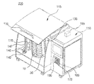
図6は、本発明の一参考例による大容量自動化細胞培養器200の正面図を示し、図7は、図6に示された大容量自動化細胞培養器200の斜視図を示しており、図8は、図6に示された大容量自動化細胞培養器200のドア105が閉められた状態を示した斜視図である。
FIG. 6 shows a front view of a large-volume automated
図6乃至図8を参照すると、本発明の他の参考例による大容量自動化細胞培養器200は、内部に空いた空間が備えられて、一面を開閉できるようにドア115が設けられた直六面体形状の本体110と、前記本体110の空いた空間の下部面に備えられて、回転運動をする回転駆動器120と、細胞培養フラスコ収容部30に細胞培養フラスコ10と注入装置50と回収装置60が備えられた細胞培養装置100と、細胞培養フラスコ収容部30の連結部36上に備えられて、前記細胞培養フラスコ10の一部面を取り囲む多数の半円板状の支持部132、前記支持部132の側面に付着され、支持部132が前後に作動するように往復運動する多数の第1ロボットアーム134と、前記多数の第1ロボットアーム134の一端を収容し、各第1ロボットアーム134を個別的に作動させる駆動機構136で構成されるプッシュユニット130と、回転駆動器120の側面に設けられた垂直フレーム142上で垂直に往復運動する第2ロボットアーム146の端部に設けられた観察ユニット140とを含む。
Referring to FIGS. 6 to 8, a large-capacity automated
支持部132上に備えられた細胞培養フラスコ10は、前記プッシュユニット130の第1ロボットアーム134の作動により、個別的に外部に突出される。
The
細胞培養装置100は、透明な物質からなる密閉された円筒形の細胞培養フラスコ10と、前記細胞培養フラスコ10内部に培養液を供給できる注入装置50と、前記細胞培養フラスコ10内部から培養液を抽出できる回収装置60と、前記注入装置50と回収装置60を収容できる多数の注入部33と回収部35が垂直方向に備えられた、互いに向かい合っている注入部垂直フレーム32と回収部垂直フレーム34、前記向かい合って設けられた二つの垂直フレームの上端と下端との間を一定間隔で連結する板状の連結部36から構成される細胞培養フラスコ収容部30とを含む。
The
大容量自動化細胞培養器200は、本体110内部の一側面に備えられて、本体110内部の温度を調節する温度調節部160と、本体110内部の一側面に備えられて、細胞培養装置100にガスを供給するガス供給部170と、本体110内部の上部面に備えられて、紫外線を供給する紫外線供給ユニット150と、細胞培養装置100に備えられた注入装置50または回収装置60とチューブ182で連結されており、培養液を臨時貯蔵できるビン形態の培養液貯蔵部180とをさらに含むことができる。
The large-capacity automated
大容量自動化細胞培養器200のドア115は、取っ手が備えられて、本体110と連結される端面に、リンクで連結された棒状の部材117が設けられて、本体の上部面上に両側鉤118が形成されて、前記ドア115の棒状の部材117が前記両側鉤118に拘束されて開閉が可能である。
The
細胞培養装置100は、図1乃至図5で詳細に説明したため、ここでは具体的な説明を省く。
Since the
図9は、細胞培養フラスコ収容部30にプッシュユニット130が備えられた状態を示した斜視図であり、図10は、細胞培養装置100にプッシュユニット130が備えられた状態を示した斜視図であって、図11は、図10に示した細胞培養装置100にプッシュユニット130が備えられた状態の正面図を透視して示したものである。
FIG. 9 is a perspective view showing a state in which the
図9をみると、プッシュユニット130の駆動機構136上に垂直に備えられた多数の第1ロボットアーム134の端部に付着された多数の支持部132は、細胞培養フラスコ収容部30の各連結部36の上面に設けられる。
Referring to FIG. 9, a large number of
プッシュユニット130の駆動機構136を作動させることにより、多数の第1ロボットアーム134は、前後往復運動が可能である。一回作動する時、第1ロボットアーム134が一つだけ作動することも、数個の第1ロボットアーム134が同時に作動することもできる。
By actuating the
駆動機構136は、油圧で動く装置である。
The
第1ロボットアーム134は、頻繁に前後往復運動をするため、摩擦に強い材質から形成することが好ましく、錆がつかないようにステンレスのような材質から形成することができる。
Since the
図10をみると、細胞培養フラスコ収容部30に細胞培養フラスコ10と注入装置50、回収装置60が備えられた細胞培養装置100を示している。
FIG. 10 shows a
プッシュユニット130の駆動機構136を作動することにより、第1ロボットアーム134が前後に動き、第1ロボットアーム134の端部に付着された支持部132に備えられた細胞培養フラスコ10も支持部132と共に前後に動くことができる。
By operating the
図11を見ると、プッシュユニット130の支持部132上に細胞培養フラスコ10が備えられたことが分かる。中央部から垂直方向に表現された長い長方形の線は、駆動機構136を表現したものである。注入装置50と回収装置60は、注射器形態の同一な形態を有しており、ケーブル70により電気を供給される。
Referring to FIG. 11, it can be seen that the
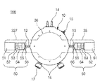
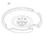
図12は、回転駆動器120の斜視図を示しており、図13は、回転駆動器120の正面図、図14は、回転駆動器120に備えられた回転部129の斜視図である。また、図15は、回転駆動器120に備えられた駆動部121の斜視図である。
12 is a perspective view of the
図12と図13を見ると、回転駆動器120は、外部から電気が供給されて作動するモーター119、モーター119から動力が伝達されて回転する回転部129、回転部129の上側に備えられて、回転部129が回転する場合、停止された状態を維持して、回転部129の回転方向によって傾きだけが変化する駆動部121を含む。
Referring to FIGS. 12 and 13, the
電気が供給されて作動するモーター119の代わりに、電動機または発電機のような他の動力供給装置を使用することができる。
Instead of a
図14を見ると、回転部129は、モーター119に一側端部が固定されており、モーター119から動力が伝達されて回転する回転軸128、回転軸128下端に付着されており、回転軸128を回転支持する円板状第1支持台126、第1支持台126の下端に備えられ、前記回転軸128に前記第1支持台126が固定できるようにする第1支持台固定部127、第1支持台126の上部に設けられて、第1支持台126とヒンジ部材125で連結されており、中央に穴の開いた円板状第2支持台124、第2支持台124の上部面の円周上に設けられて、ボールベアリング123の一部面が収容できるように球形態の溝が形成された円筒形のボールベアリング収容部122、ボールベアリング収容部122で回転作動するボールベアリング123を含む。
Referring to FIG. 14, the
回転部129は、モーター119から動力が供給されて回転運動をし、駆動部121は、回転部129に対応して動くが、回転部129の回転運動に係わらず停止した状態を維持する。モーター119に固定された回転軸128は、断面が円形の棒形態であって、モーターに固定が可能であれば、正方形や三角形断面の棒が使用でいる。
The
駆動部121と接する回転軸128の端部は、角だった形状である場合、回転により磨耗されるか構成部品が破損する恐れがあるため、球形態の端部を使用することが好ましい。
When the end portion of the
第1支持台126は、モーター119に固定された回転軸128が回転支持されるようにするために回転軸128の下端に備えられて、回転軸128は、第1支持台126の中央部を貫通する。回転時、安定した平衡状態を維持するためには、円板形を使用することが好ましいが、他の形態の板を使用することもできる。
The
第1支持台固定部127は、第1支持台126の下部に設けられて、第1支持台126を回転軸128に固定する役割をする。即ち、単純に回転軸128に第1支持台126のみを付着して回転させたら、重力または遠心力により第1支持台126が回転軸128から分離される恐れがあるため、第1支持台126を支持するための役割をする。
The first support
また、第1支持台126の荷重を支える機能をする。したがって、第1支持台固定部127は、ゴムまたは弾性力のある他の部材が使用できる。
Also, it functions to support the load of the
第2支持台124は、第1支持台126の上部に設けられて、第2支持台124を支持するようにするために、第1支持台126と台2支持台124との間にはヒンジ部材125が設けられる。第2支持台124の荷重は、ヒンジ部材125により第1支持台126に分散される。
The
本発明におけるヒンジ部材125は、その中心軸が外部面と結合される両接合部の中央に備えられる。したがって、中心軸が一側に存在し、一側方向にのみ回転可能な一般的なヒンジ部材とは異なって、時計または反時計方向に自由に角度調節が可能である。
The
第2支持台124の中央は、開口部が備えられており、回転軸128の球状の端部は、開口部を通じて上側に突出しており、駆動部121と噛み合って作動する。
The center of the
第2支持部124の上部面の円周上には、ボールベアリング123の一部面が収容できるように、球形態の溝が形成された円筒形ボールベアリング収容部122が備えられる。
On the circumference of the upper surface of the
ボールベアリング123は、ボールベアリング収容部122の溝に嵌められて回転運動をする。ボールベアリング収容部122は、ボールベアリング123との摩擦によりかなりの熱が発生するため、熱に強い耐熱性物質で製造されたものがよい。
The
ボールベアリング収容部122とこれに設けられて作動するボールベアリング123は、ボールベアリング123に対応して動く駆動部121が均衡を失わないように、三つ以上備えられることが好ましい。各ボールベアリング収容部122が三つであれば、120°の同一間隔で離隔されて設けられるため、駆動部121が中心を失わずに安定して作動できる。
It is preferable that three or more
回転駆動器120を示した図15を参照すると、回転駆動器120の駆動部121は、細胞培養装置100が装着できる円板の形態であり、円板の底部分には、回転部129の回転軸128の球状の端部に接して動くように内部が球状に削られた部材が設けられる。
Referring to FIG. 15 showing the
回転部129のボールベアリング123は、回転駆動器120の駆動部121の底面に直接接触して作動し、駆動部121の底面には、ボールベアリング123が円滑に回転できるように円周に沿って一定な幅のボールベアリング123経路が形成される。
The
以下、図12乃至図15を参照して回転駆動器120の作動原理を説明する。
Hereinafter, the operation principle of the
モーター119が作動する場合、モーター119に固定された回転軸128は、動力が伝達されて回転するようになる。回転軸128の回転時、回転軸128に固定されている第1支持台126と第1支持台固定部127も回転するようになり、第2支持台124は、第1支持台126とヒンジ部材125により連結されて回転するようになる。
When the
回転部129が全体的に回転する時、第2支持台124の上部面に設けられたボールベアリング123は、回転部129の回転方向と逆方向に回転するようになる。これは、ボールベアリング123のボールベアリング収容部122に接した面とボールベアリング123の駆動部121に接した面上で発生する摩擦力のためである。
When the
ボールベアリング123が回転部129の回転方向と反対方向に回転するため、ボールベアリング123と接する駆動部121は回転せず、停止した状態を維持することができる。回転軸128の球状の端部は、駆動部121の底面に形成された、内部が球状に削られた部材と噛み合って作動するが、ボールベアリング123の回転により、駆動部121全体の動きには影響を与えず、駆動部121は停止した状態を維持する。
Since the
回転軸128が回転する時、ヒンジ部材125が中心軸を基準に一側方向に傾くと、第2支持台124とこれに対応して動く細胞培養装置100も同様に傾くようになる。
When the
回転部129が傾いた状態で回転する時、ボールベアリング123の回転により、駆動部121が回転しない状態を維持するため、駆動部121は、回転部129の回転方向に傾きだけが変化しながら周期的に動くようになる。
When the
即ち、回転部129のヒンジ部材125が傾いた方向に駆動部121が傾くようになり、回転部129の回転により、傾いた方向は変化するため、駆動部121の傾いた方向も変化するようになる。但し、駆動部121は、ボールベアリング123の回転によって回転運動をするものではない。
That is, the driving
このような動きの繰り返しにより駆動部121の上面に備えられた細胞培養装置100の内部で培養される細胞は適宜混ざるようになり、培養液が均一に分配されて、細胞培養装置内の細胞が均一に成長できるようにすることができる。
The cells cultured in the
即ち、駆動部121の回転駆動により、細胞培養装置100内に付着された細胞の一部は培養液内に浸されており、一部は細胞培養装置100の内部空間中に露出するため、全体面積が培養液内に浸されて培養される一般的なフラスコ培養に比べ、培養液の消耗量を減少させることができるという長所がある。そして、回転駆動により酸素供給が十分になされるため、既存培養法に比べて培養細胞のブドウ糖代謝において安定性が増加する。
That is, a part of the cells attached in the
また、実験者が手動で細胞培養装置を振る必要がないため便利であり、大きい摩擦力が発生しないため破損の心配がなく、長期間使用することができる。 Further, it is convenient because the experimenter does not need to manually shake the cell culture apparatus, and since a large frictional force is not generated, there is no fear of breakage, and it can be used for a long time.
また、別途に自動制御装置を備えて、回転部129の回転速度を調節することもできる。
In addition, an automatic control device can be provided separately to adjust the rotation speed of the
図16は、細胞培養装置100が設けられていない大容量自動化細胞培養器200の正面図であり、図17は、大容量自動化細胞培養器200の温度調節部160を示した図面である。
FIG. 16 is a front view of a large-capacity automated
図16を参照すると、回転駆動器120の駆動部121の上部に細胞培養装置100が備えられていない状態であって、大容量自動化細胞培養器200の内部には、プッシュユニット130、回転駆動器120の側面に設けられた観察ユニット140、内部温度を調節する温度調節部160、ガス供給ができるガス供給部170、本体内部に紫外線を供給する紫外線供給ユニット150、回収された培養液を貯蔵できる培養液貯蔵部180が備えられる。
Referring to FIG. 16, the
回転駆動器120の側面には、垂直フレーム142が備えられて、垂直フレーム142上で垂直に往復運動をする移送部材144には、第2ロボットアーム146が備えられる。第2ロボットアーム146の回転駆動器120方向の端部には、観察ユニット140が設けられる。垂直フレーム142上で移送部材144が垂直運動する時、第2ロボットアーム146は、左右に動けるように作動される。これにより、第2ロボットアームの端部に備えられた観察ユニット140は、使用者が観察しようとする所に移動可能である。即ち、垂直運動と水平運動が可能であって、自由に2次元運動が可能である。
A
観察ユニット140は、倍率調節が可能なCCDカメラを使用することができる。
The
細胞培養装置100が設けられた場合、CCDカメラを利用して細胞培養フラスコ10内で生長している細胞を外部から容易に観察することができる。
When the
また、蓄積プログラムを設定して、観察した細胞の数量と培養状態の写真を蓄積するようにできる。 In addition, an accumulation program can be set to accumulate photographs of the observed cell quantity and culture state.
ガス供給部170は、本体内部の下部面または側面に備えられて、細胞培養装置100の細胞培養フラスコ10内部にガスを供給する。これにより各種ガスを一定に供給可能である。ガスの供給量を表示するために、本体110の正面にはガス量表示部172が設けられる。また、液晶表示部190を利用してガス量を外部に表示することができる。
The
本体110内部の上部面には、紫外線を供給する紫外線供給ユニット150が備えられる。紫外線供給ユニット150には、青色を帯びる紫外線などが利用できて、本体110内部を滅菌する役割をする。
An
培養液貯蔵部180は、本体110内部の底面にビン形態として備えられて、細胞培養装置100の注入装置50または回収装置60とチューブで連結されており、培養液を臨時貯蔵することができる。必要に応じて、一つまたは多数が備えられる。
The culture
図16と図17を参照すると、温度調節部160は、大容量自動化細胞培養器200の裏面に設けられて、本体110内部の温度を調節する。
Referring to FIGS. 16 and 17, the
温度調節部160は、本体110の一側面に備えられて、本体110内部に外部空気を供給するファン162と、ファン162が設けられた本体110の内部面上でファン162と近接するように備えられて、ファン162から供給された外部空気を浄化するヘパフィルター164と、ヘパフィルター164と近接して設けられて、ヘパフィルター164から供給された浄化された空気に熱を供給する熱パイプ166と、本体110内部の一側面に備えられて、本体110内部の温度を測定する温度センサー168と、温度センサー168から受信された温度が設定温度より低い場合、ファン162と熱パイプ166を作動するようにする制御部195とを含む。
The
ヘパフィルター164が設けられることにより、空気清浄機能のある装置を別途に設ける必要がなく、本体110内部をきれいに維持することができる。
By providing the
熱パイプ166は、曲がった状態として備えられて、一遍に多い量の熱を供給することができ、熱効率がよい。
The
温度センサー168により測定された温度は、本体110の前面に備えられた温度表示部169に表示される。また、液晶表示部190を利用して測定温度を外部に表示できる。
The temperature measured by the
制御部195は、細胞培養装置100に供給されるガス量を制御することができ、細胞培養装置100の注入装置50と回収装置60を制御し、培養液を供給するか抽出することができる。
The
図18は、大容量自動化細胞培養器200が作動している状態を示した図面である。使用者が大容量自動化細胞培養器200を作動した場合、回転駆動器120が回転することにより、細胞培養装置100は、円周方向に沿って傾きが変化する。
FIG. 18 is a diagram showing a state in which the large-capacity automated
使用者が細胞培養装置100に備えられた細胞培養フラスコ10内部を観察しようとする時、垂直フレーム142とロボットアーム146の2次元的な動きを調節して、観察ユニット140を観察しようとする細胞培養フラスコ10の近所に移動させることができる。その後、外部から観察ユニット140を通じて細胞培養フラスコ10内部で生長している細胞を観察し、培養液の不足程度、細胞の成長程度を判別することができる。
When the user wants to observe the inside of the
その他、大容量自動化細胞培養器200内にプログラムを設定し、これにより、回転駆動器120の回転駆動、培養液の注入と排出、細胞培養器200内の温度調節、ガス調節が自動に作動できるようにする。これは、もちろん制御部195により制御される。
In addition, a program is set in the large-capacity automated
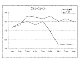
図19は、本発明による大容量自動化細胞培養器200を使用した場合と、一般的なフラスコを使用した場合、膝軟骨細胞の増加倍数を示した図面であり、図20は、本発明による大容量自動化細胞培養器200を使用した場合と、一般的なフラスコを使用した場合、膝軟骨細胞の培養期間の間、一日毎に測定したブドウ糖レベル(glucose level)を示した図面である。
FIG. 19 is a diagram showing an increase in the number of knee chondrocytes when the large-capacity automated
ヒトの膝軟骨から採取した細胞(Articular Cartilage Cells;AC cells)を、本発明による大容量自動化細胞培養器200を利用して培養した。冷凍保存された第8経路(passase)の膝軟骨細胞を解凍した後、850cells/cm2の低い密度で細胞培養装置100にシーディング(seeding)し、培地交換をせずに9日間培養した。
Cells (Articular Cartilage Cells; AC cells) collected from human knee cartilage were cultured using the large-capacity automated
細胞を培養する間、細胞培養装置100内のCO2濃度は6.5%、温度は37℃、細胞培養フラスコ10回転速度は1rpmに維持されるようにパラメータ(parameter)を入力した。対照装置として、一般的なフラスコ(T-25フラスコ)に同一な細胞を、面積に対して同一な数でシーディングして培養条件(CO2濃度6.5%、温度37℃)を同一に維持しながら、CO2インキュベーターで静置培養した。
During the cell culture, parameters were input so that the CO 2 concentration in the
シーディングした膝軟骨細胞は9日間培養しながら、1日毎に細胞数を測定して増加倍数を計算し、1日毎に血糖測定器(glucometer)を利用してブドウ糖水準(glucose level)を測定した。その結果、細胞増加倍数は、二つの群がほぼ等しかったが、ブドウ糖(glucose level)は、T−25フラスコに比べ、本発明の細胞培養装置100でさらに高く現れた。即ち、本発明の細胞培養装置100では、回転駆動により酸素供給が十分なされるため、細胞培養過程上のブドウ糖(glucose)の減少幅が減って、既存のフラスコ(T-25)を利用した静置培養よりエネルギー代謝効率がさらによいことが分かる。
The seeded knee chondrocytes were cultured for 9 days, the number of cells was measured every day to calculate the multiplication factor, and the glucose level was measured every day using a glucometer. . As a result, the cell multiplication factor was almost equal in the two groups, but glucose level appeared higher in the
ブドウ糖(glucose)は、培地内に一般的に含まれている細胞のエネルギー源として酸素供給が十分である場合、体内で該当過程(glycolysis)を通じてピルビン酸(pyruvate)に代謝された後、クエン酸回路(citric acid cycle)に入って酸化され、二酸化炭素と水に変わる。しかしながら、酸素呼吸で必要な酸素が速く供給されないと、細胞はエネルギーを生産するために、該当過程を経たピルビン酸(pyruvate)がクエン酸回路に正常的に入れず、乳酸発酵(lactate fermentation)過程を経る。この場合、ブドウ糖(glucose)の代謝のために該当過程のみが繰り返されて、クエン酸回路が正常的に作動せず、乳酸(lactate;lactic acid)が蓄積される。 Glucose is metabolized to pyruvate through the corresponding process (glycolysis) and then citrate after the oxygen supply is sufficient as an energy source for cells generally contained in the medium. It enters the circuit (citric acid cycle) and is oxidized to carbon dioxide and water. However, if the oxygen required for oxygen respiration is not supplied quickly, the cells will produce energy, so pyruvic acid that has undergone the relevant process does not normally enter the citric acid cycle, and the lactate fermentation process Go through. In this case, only the corresponding process is repeated for glucose metabolism, the citric acid cycle does not operate normally, and lactic acid (lactate) is accumulated.
同一な細胞の増加率に比べ、ブドウ糖レベル(glucose level)が減少する現象は、酸素の不足により、培養中の細胞内のクエン酸回路が体内でのようによく機能していないことを意味する。即ち、回転駆動による本発明の培養方法が、既存のフラスコ(T-25)を使用した静置培養より、正常的なブドウ糖代謝が起こる有利な方法であることを意味する。 The phenomenon that glucose level decreases compared to the rate of increase of the same cell means that the citrate cycle in the cells in culture is not functioning as well as in the body due to lack of oxygen. . That is, it means that the culture method of the present invention by rotational drive is an advantageous method in which normal glucose metabolism occurs compared to the stationary culture using the existing flask (T-25).
本発明の参考例及び実施例で使用した細胞培養フラスコ10は、円筒形の培養管内部に細胞が付着できるため、細胞が付着して成長できる空間が極大化されて、回転駆動により、培養管に付着された細胞の一部は培養液内に浸されており、一部は培養管の内部空間中に露出するため、細胞は、培地と空気を交互に接触することができ、円滑に酸素の供給がなされるため、上記のような結果が現れることが分かる。
The
以上、本発明の好ましい実施例について記述したが、本発明は、上述の特定の実施例に限定されない。即ち、本発明の属する技術分野で通常の知識を有するものなら、添付の特許請求の範囲の思想及び範囲を逸脱することなく様々な変更や修正が可能であり、このような全ての適切な変更及び修正の等価物も本発明に属すると言える。 Although the preferred embodiments of the present invention have been described above, the present invention is not limited to the specific embodiments described above. That is, a person having ordinary knowledge in the technical field to which the present invention pertains can make various changes and modifications without departing from the spirit and scope of the appended claims. And equivalents of modifications also belong to the invention.
10 細胞培養フラスコ
11 培養空間
12 培養液流入口
13 培養液排出口
14 ガス流入口
15 ガス排出口
16 異物流入口
17 栓
30 細胞培養フラスコ収容部
32 注入部垂直フレーム
33 注入部
34 回収部垂直フレーム
35 回収部
36 連結部
50 注入装置
60 回収装置
70 ケーブル
100 細胞培養装置
110 本体
115 ドア
120 回転駆動器
130 プッシュユニット
134 第1ロボットアーム
140 観察ユニット
150 紫外線供給ユニット
160 温度調節部
170 ガス供給部
180 培養液貯蔵部
190 液晶表示部
200 大容量自動化細胞培養器
DESCRIPTION OF
Claims (10)
動力供給部により回転する回転部と、
回転部の上部に位置し、回転部が回転する時、停止状態を維持することにより、回転部の回転方向によってのみ傾きが変わる駆動部と、を含む細胞培養用回転駆動器。 A power supply unit that is operated by receiving electric power from outside;
A rotating unit that is rotated by a power supply unit;
A rotation driver for cell culture, comprising: a drive unit that is located at an upper part of the rotation unit and that changes its inclination only by the rotation direction of the rotation unit by maintaining a stopped state when the rotation unit rotates.
前記動力供給装置に一側端部が固定されており、前記動力供給装置から動力を伝達されて回転する回転軸と、
前記回転軸下端に付着されており、前記回転軸の回転を支持する円板状第1支持台と、
前記第1支持台の上部に設けられて、前記第1支持台と多数個のヒンジ部材で連結されており、中央に開口部が備えられた円板状第2支持台と、
前記第2支持台の上部面の円周上に設けられて、ボールベアリングの一部面を収容できるように球状の溝が形成された円筒形のボールベアリング収容部と、
前記ボールベアリング収容部で回転作動するボールベアリングと、を含むことを特徴とする、請求項1に記載の細胞培養用回転駆動器。 The rotating part is
One end portion is fixed to the power supply device, and a rotating shaft that rotates by receiving power from the power supply device;
A disk-shaped first support that is attached to the lower end of the rotating shaft and supports the rotation of the rotating shaft;
A disc-shaped second support base provided at the upper part of the first support base, connected to the first support base by a plurality of hinge members, and having an opening at the center;
A cylindrical ball bearing receiving portion provided on a circumference of the upper surface of the second support base and having a spherical groove formed so as to receive a part of the surface of the ball bearing;
The rotation driver for cell culture according to claim 1, further comprising a ball bearing that rotates in the ball bearing housing portion.
上部表面は細胞培養装置収容部の下部表面に固定されて、下部表面は球状の溝を有し、回転部上端の回転軸の球形末端が中央に挿入される電力伝送部と、を含むことを特徴とする、請求項1に記載の細胞培養用回転駆動器。 The drive unit is a disk-shaped cell culture device housing unit having a space in which the cell culture device is attached;
The upper surface is fixed to the lower surface of the cell culture device housing part, the lower surface has a spherical groove, and includes a power transmission part into which the spherical end of the rotating shaft at the upper end of the rotating part is inserted in the center. The rotation driver for cell culture according to claim 1, characterized in that
Applications Claiming Priority (2)
| Application Number | Priority Date | Filing Date | Title |
|---|---|---|---|
| KR1020070123914A KR100946643B1 (en) | 2007-11-30 | 2007-11-30 | The cell culture apparatus and mass automatic cell culture device having it |
| KR10-2007-0123914 | 2007-11-30 |
Related Parent Applications (1)
| Application Number | Title | Priority Date | Filing Date |
|---|---|---|---|
| JP2010535881A Division JP5197753B2 (en) | 2007-11-30 | 2008-11-28 | Cell culture device and large-capacity automated cell culture device equipped with the same |
Publications (2)
| Publication Number | Publication Date |
|---|---|
| JP2012161330A true JP2012161330A (en) | 2012-08-30 |
| JP5309245B2 JP5309245B2 (en) | 2013-10-09 |
Family
ID=40679146
Family Applications (2)
| Application Number | Title | Priority Date | Filing Date |
|---|---|---|---|
| JP2010535881A Active JP5197753B2 (en) | 2007-11-30 | 2008-11-28 | Cell culture device and large-capacity automated cell culture device equipped with the same |
| JP2012094945A Active JP5309245B2 (en) | 2007-11-30 | 2012-04-18 | Rotating drive for cell culture |
Family Applications Before (1)
| Application Number | Title | Priority Date | Filing Date |
|---|---|---|---|
| JP2010535881A Active JP5197753B2 (en) | 2007-11-30 | 2008-11-28 | Cell culture device and large-capacity automated cell culture device equipped with the same |
Country Status (5)
| Country | Link |
|---|---|
| US (1) | US9057715B2 (en) |
| EP (1) | EP2225359B1 (en) |
| JP (2) | JP5197753B2 (en) |
| KR (1) | KR100946643B1 (en) |
| WO (1) | WO2009069962A2 (en) |
Cited By (2)
| Publication number | Priority date | Publication date | Assignee | Title |
|---|---|---|---|---|
| KR20210007332A (en) * | 2019-07-11 | 2021-01-20 | 이용문 | Medium culturing apparatus |
| WO2021086136A1 (en) * | 2019-11-01 | 2021-05-06 | 주식회사라이브셀인스트루먼트 | Disk for seeding and culturing cells, real-time monitoring system, and method for seeding and culturing cells |
Families Citing this family (46)
| Publication number | Priority date | Publication date | Assignee | Title |
|---|---|---|---|---|
| KR100932861B1 (en) * | 2007-11-30 | 2009-12-21 | 코아스템(주) | Cell culture flask |
| US8778669B2 (en) | 2009-07-22 | 2014-07-15 | Corning Incorporated | Multilayer tissue culture vessel |
| JP2011160729A (en) * | 2010-02-10 | 2011-08-25 | Airtech Japan Ltd | Tissue culturing apparatus for allowing arbitrary change in gas condition |
| EP2516618B1 (en) * | 2010-05-11 | 2020-07-08 | Pall Artelis BVBA | Bioreactor for cell culture |
| WO2013145235A1 (en) * | 2012-03-29 | 2013-10-03 | 株式会社日立製作所 | Culture vessel and automated culture apparatus |
| BR112014030587A2 (en) * | 2012-06-06 | 2018-04-24 | Novozymes Bioag As | production scale solid bioreactor with a reactor vessel; and production scale solid bioreactor system. |
| KR101422345B1 (en) * | 2012-10-19 | 2014-07-22 | 한국생명공학연구원 | Dual structured cell culture dish |
| US9005550B2 (en) | 2012-10-29 | 2015-04-14 | Corning Incorporated | Multi-layered cell culture vessel with manifold grips |
| KR101731590B1 (en) * | 2013-10-16 | 2017-05-02 | 메디칸(주) | Apparatus and Method for cell culture in a continuous manner |
| KR101566083B1 (en) | 2013-10-17 | 2015-11-05 | 한국생명공학연구원 | circulating culture system |
| CN105112294A (en) * | 2015-09-15 | 2015-12-02 | 重庆大学 | Coaxial multi-incubator bioreactor |
| EP3377981B1 (en) * | 2015-11-18 | 2023-10-11 | Thrive Bioscience, Inc. | Cell culture incubator |
| WO2017154197A1 (en) * | 2016-03-11 | 2017-09-14 | 株式会社日立製作所 | Container manipulation device, cell culturing method, and device |
| KR101754751B1 (en) * | 2016-06-09 | 2017-07-20 | 주식회사 아리바이오 | Rotary cell culture system |
| US20180057784A1 (en) | 2016-08-27 | 2018-03-01 | 3D Biotek, Llc | Bioreactor |
| CN107022484A (en) * | 2017-05-27 | 2017-08-08 | 余裕炉 | A kind of Embryo Culture unit and preparation method thereof |
| CN107603880B (en) * | 2017-11-01 | 2021-03-16 | 深圳市职业病防治院 | Cell culture container |
| KR102220125B1 (en) | 2018-04-26 | 2021-02-25 | (주)세포바이오 | Automated cell culturing device and method thereof |
| CN109401966B (en) * | 2018-11-07 | 2024-09-06 | 深圳大学 | Cell culture mechanical arm |
| KR102318115B1 (en) * | 2018-11-14 | 2021-10-27 | 주식회사 아모그린텍 | Cell culture system |
| WO2020101399A1 (en) | 2018-11-14 | 2020-05-22 | 주식회사 아모그린텍 | Cell culture sheet assembly for large-capacity incubator, and large-capacity incubator comprising same |
| CN113330318A (en) | 2018-11-16 | 2021-08-31 | 爱新诺有限公司 | Module for an automated biological laboratory system with a transport plate or laboratory device |
| KR102631742B1 (en) | 2018-11-16 | 2024-01-30 | 아익시노 리미티드 | Handling system for handling lab-ware in lab-ware and cell culture processes |
| JP2022518101A (en) | 2018-11-16 | 2022-03-14 | アイキシンノ・リミテッド | Process module for automated biological systems |
| EP3881081B1 (en) | 2018-11-16 | 2024-03-06 | Aixinno Limited | A system for processing biology material, |
| CN109679848B (en) * | 2018-12-28 | 2022-05-06 | 江西汉氏联合干细胞科技有限公司 | Culture device for pluripotent stem cells and application of culture device |
| JP2022123160A (en) * | 2019-07-04 | 2022-08-24 | 株式会社京都製作所 | Culture device and culture method |
| US20220340852A1 (en) | 2019-09-06 | 2022-10-27 | Amolifescience Co., Ltd. | Cell culture sheet and large-capacity cell culture device including same |
| CN110564599B (en) * | 2019-09-24 | 2023-01-03 | 西安市第四医院 | Anti-pollution formula bacteria culture device of clinical laboratory |
| CN111019824B (en) * | 2019-12-16 | 2024-02-02 | 浙江卫未生物医药科技有限公司 | Automatic level machine suitable for cell culture |
| CN111337493B (en) * | 2020-03-18 | 2022-12-06 | 湖北和诺生物工程股份有限公司 | Tobacco cell suspension culture solution detection device and method |
| CN111500443B (en) * | 2020-04-20 | 2023-09-05 | 湖南旭智生物科技有限公司 | Culture device for hair follicle stem cell induced differentiation and use method |
| CN111440716B (en) * | 2020-04-20 | 2024-01-23 | 深圳市华晨阳科技有限公司 | Culture device for hair follicle stem cell induced differentiation and use method |
| CN111411042B (en) * | 2020-04-20 | 2023-09-01 | 深圳格泰赛尔生物科技有限公司 | Injection device for hair follicle stem cell culture and use method |
| CN111557301B (en) * | 2020-05-14 | 2021-08-06 | 浙江玉安康瑞生物科技有限公司 | Cell culture ice deposits equipment |
| CN111718838B (en) * | 2020-06-24 | 2023-04-11 | 浙江省海洋水产研究所 | Illumination incubator structure |
| EP3933024B1 (en) * | 2020-07-02 | 2022-10-26 | LG Chem, Ltd. | Gas collection device |
| KR102553667B1 (en) * | 2020-07-02 | 2023-07-11 | 주식회사 엘지화학 | Gas collection device |
| US11732232B2 (en) | 2020-08-14 | 2023-08-22 | Korea Research Institute Of Bioscience And Biotechnology | Biomimetic cell culture apparatus and cell culture system comprising the same |
| CN112522105B (en) * | 2021-01-07 | 2022-08-26 | 华润昂德生物药业有限公司 | CHO cell bottle culture all-in-one machine |
| CN113637584B (en) * | 2021-07-31 | 2024-09-13 | 顾怀飞 | Constant-temperature biological cell engineering incubator and use method thereof |
| CN113773960B (en) * | 2021-09-18 | 2023-09-26 | 湖南格致生物科技有限公司 | Culture device and culture method for high-purity stem cells |
| CN114574317B (en) * | 2022-01-25 | 2024-04-09 | 长春中医药大学 | Press mounting device for multilayer cell culture plates |
| FR3137923A1 (en) * | 2022-07-13 | 2024-01-19 | Adhara | Cell tissue culture facility |
| CN116179342B (en) * | 2022-11-15 | 2023-12-19 | 东营凤起生物科技发展有限公司 | Neural stem cell expansion device and method thereof |
| CN118086054B (en) * | 2024-04-26 | 2024-07-09 | 山东大华凯特生物集团有限公司 | Virus suspension culture equipment |
Citations (6)
| Publication number | Priority date | Publication date | Assignee | Title |
|---|---|---|---|---|
| JPS63167899U (en) * | 1987-04-23 | 1988-11-01 | ||
| JPH01124379A (en) * | 1987-11-06 | 1989-05-17 | Shimadzu Corp | Culture apparatus |
| JPH037575A (en) * | 1989-03-30 | 1991-01-14 | Shimadzu Corp | Apparatus for cell culture |
| JPH0310679A (en) * | 1989-06-09 | 1991-01-18 | Shimadzu Corp | Cell culture bag |
| JPH1047231A (en) * | 1996-08-02 | 1998-02-17 | Zexel Corp | Variable capacity type compressor |
| WO2007097121A1 (en) * | 2006-02-21 | 2007-08-30 | Scivax Corporation | Spheroid, spheroids and method of producing the same |
Family Cites Families (27)
| Publication number | Priority date | Publication date | Assignee | Title |
|---|---|---|---|---|
| US4307193A (en) * | 1978-06-09 | 1981-12-22 | Toray Industries, Inc. | Method of producing interferon |
| US4335215A (en) * | 1980-08-27 | 1982-06-15 | Monsanto Company | Method of growing anchorage-dependent cells |
| US4639422A (en) * | 1986-02-03 | 1987-01-27 | Monsanto Company | Cell culture filter apparatus and method |
| JPS63298161A (en) * | 1987-05-29 | 1988-12-05 | Sumitomo Electric Ind Ltd | Distributor |
| US5350080A (en) * | 1993-02-10 | 1994-09-27 | Hyclone Laboratories | Multi-access port for use in a cell culture media system |
| US5424209A (en) * | 1993-03-19 | 1995-06-13 | Kearney; George P. | Automated cell culture and testing system |
| ATE204322T1 (en) * | 1995-06-07 | 2001-09-15 | Aastrom Biosciences Inc | DEVICE AND METHOD FOR STORING AND CULTURING BIOLOGICAL CELLS |
| TW491892B (en) * | 1996-11-07 | 2002-06-21 | Srl Inc | Apparatus for detecting microorganism |
| US5961934A (en) * | 1998-02-18 | 1999-10-05 | Biospace International Inc. | Dynamically controlled crystallization method and apparatus and crystals obtained thereby |
| KR100294247B1 (en) * | 1999-06-19 | 2001-06-15 | 윤종용 | Digital data interpolation apparatus |
| GB0020058D0 (en) * | 2000-08-16 | 2000-10-04 | Smiths Industries Plc | Syringe pumps |
| JP3545324B2 (en) * | 2000-09-06 | 2004-07-21 | 三洋電機株式会社 | Culture device |
| KR100394247B1 (en) * | 2001-02-05 | 2003-08-06 | 주식회사 케이티앤지 | A cell cultivating device |
| US6673595B2 (en) * | 2001-08-27 | 2004-01-06 | Biocrystal, Ltd | Automated cell management system for growth and manipulation of cultured cells |
| US20060223155A1 (en) * | 2002-11-01 | 2006-10-05 | Jackson Streeter | Enhancement of in vitro culture or vaccine production in bioreactors using electromagnetic energy |
| JP2004254516A (en) * | 2003-02-24 | 2004-09-16 | Olympus Corp | Method for cell culture, method for producing biological tissue supply material, apparatus for cell culture and apparatus for producing biological tissue supply material |
| ES2405738T3 (en) * | 2003-02-28 | 2013-06-03 | Nunc A/S | Tray stack adapted for active gassing |
| JP4433742B2 (en) | 2003-09-22 | 2010-03-17 | 株式会社ジェイ・エム・エス | Culture container, culture using the culture container, and method for producing the culture |
| US20070020754A1 (en) * | 2003-10-20 | 2007-01-25 | Rui Yuge | Cell handling device, human tissue regeneration composition, and human tissue regeneration method |
| JPWO2005059091A1 (en) * | 2003-12-18 | 2007-12-13 | 株式会社日立メディコ | Cell culture equipment |
| JP2006174828A (en) * | 2004-11-29 | 2006-07-06 | Olympus Corp | Biological sample-culturing and observing system, incubator box, supply means, and culture container |
| JP4740584B2 (en) * | 2004-12-14 | 2011-08-03 | オリンパス株式会社 | Observation device |
| US7682823B1 (en) * | 2005-01-04 | 2010-03-23 | Larry Runyon | Bioreactor systems |
| KR101249928B1 (en) * | 2005-03-29 | 2013-04-03 | 나부테스코 가부시키가이샤 | Swing part structure of industrial robot |
| JP5101819B2 (en) | 2006-01-16 | 2012-12-19 | 株式会社カネカ | Cell culture equipment |
| US9868095B2 (en) * | 2007-05-02 | 2018-01-16 | Finesse Solutions, Inc. | Disposable bioreactor system |
| KR100932861B1 (en) * | 2007-11-30 | 2009-12-21 | 코아스템(주) | Cell culture flask |
-
2007
- 2007-11-30 KR KR1020070123914A patent/KR100946643B1/en active IP Right Grant
-
2008
- 2008-11-28 JP JP2010535881A patent/JP5197753B2/en active Active
- 2008-11-28 US US12/745,029 patent/US9057715B2/en active Active
- 2008-11-28 EP EP08855371.4A patent/EP2225359B1/en active Active
- 2008-11-28 WO PCT/KR2008/007037 patent/WO2009069962A2/en active Application Filing
-
2012
- 2012-04-18 JP JP2012094945A patent/JP5309245B2/en active Active
Patent Citations (6)
| Publication number | Priority date | Publication date | Assignee | Title |
|---|---|---|---|---|
| JPS63167899U (en) * | 1987-04-23 | 1988-11-01 | ||
| JPH01124379A (en) * | 1987-11-06 | 1989-05-17 | Shimadzu Corp | Culture apparatus |
| JPH037575A (en) * | 1989-03-30 | 1991-01-14 | Shimadzu Corp | Apparatus for cell culture |
| JPH0310679A (en) * | 1989-06-09 | 1991-01-18 | Shimadzu Corp | Cell culture bag |
| JPH1047231A (en) * | 1996-08-02 | 1998-02-17 | Zexel Corp | Variable capacity type compressor |
| WO2007097121A1 (en) * | 2006-02-21 | 2007-08-30 | Scivax Corporation | Spheroid, spheroids and method of producing the same |
Cited By (3)
| Publication number | Priority date | Publication date | Assignee | Title |
|---|---|---|---|---|
| KR20210007332A (en) * | 2019-07-11 | 2021-01-20 | 이용문 | Medium culturing apparatus |
| KR102316378B1 (en) | 2019-07-11 | 2021-10-22 | 이용문 | Medium culturing apparatus |
| WO2021086136A1 (en) * | 2019-11-01 | 2021-05-06 | 주식회사라이브셀인스트루먼트 | Disk for seeding and culturing cells, real-time monitoring system, and method for seeding and culturing cells |
Also Published As
| Publication number | Publication date |
|---|---|
| WO2009069962A2 (en) | 2009-06-04 |
| EP2225359A4 (en) | 2012-01-11 |
| JP5197753B2 (en) | 2013-05-15 |
| EP2225359B1 (en) | 2016-03-16 |
| JP5309245B2 (en) | 2013-10-09 |
| KR100946643B1 (en) | 2010-03-09 |
| EP2225359A2 (en) | 2010-09-08 |
| JP2011504748A (en) | 2011-02-17 |
| WO2009069962A3 (en) | 2009-08-06 |
| KR20090056667A (en) | 2009-06-03 |
| US9057715B2 (en) | 2015-06-16 |
| US20100304472A1 (en) | 2010-12-02 |
Similar Documents
| Publication | Publication Date | Title |
|---|---|---|
| JP5309245B2 (en) | Rotating drive for cell culture | |
| KR101103693B1 (en) | Cell Culture Tube of Syringe Shape and Multiple Cell Culture Device Using the same | |
| KR100932861B1 (en) | Cell culture flask | |
| US7198940B2 (en) | Bioreactor apparatus and cell culturing system | |
| CN102296029B (en) | Perfusion bioreactor system | |
| KR100932863B1 (en) | Rotary Drive for Cell Culture | |
| US20050186669A1 (en) | Apparatus and method for preparing and culturing cells | |
| JP2002335946A (en) | Cell-culturing tube and massively cell-culturing device using the same | |
| KR20190010709A (en) | Continuously controlled hollow fiber bioreactor | |
| CN101965394B (en) | Method and device for cell culture in the open continuous mode | |
| CN105255731B (en) | Circumfusion formula cell culture system and bioreactor thereof | |
| CN106190838B (en) | A kind of organism culturing device based on haemodialyser | |
| CN208883905U (en) | The adjustable cell culture apparatus of medical experiment oxygen-supplying amount | |
| CN206308363U (en) | A kind of parallel bioreactor system | |
| CN112899161A (en) | Cell culture device | |
| CN217025936U (en) | Cell culture bottle | |
| CN209836205U (en) | Animal cell incubator | |
| JP4445765B2 (en) | Cell culture equipment | |
| CN208081875U (en) | A kind of separate type evaporator for bio-pharmaceuticals | |
| KR100953518B1 (en) | A Cell Culture Device Having The Cell Culture Flask | |
| KR101044364B1 (en) | Apparatus for Multiple Cell Culture | |
| JP3641123B2 (en) | Virus or cell culture method | |
| US3591460A (en) | Apparatus and means for handling cells | |
| CN220537817U (en) | Microorganism culture vessel based on biotechnology development usefulness | |
| KR20200111476A (en) | Plant tissue culture apparatus |
Legal Events
| Date | Code | Title | Description |
|---|---|---|---|
| A977 | Report on retrieval |
Free format text: JAPANESE INTERMEDIATE CODE: A971007 Effective date: 20121206 |
|
| A521 | Request for written amendment filed |
Free format text: JAPANESE INTERMEDIATE CODE: A523 Effective date: 20130415 |
|
| TRDD | Decision of grant or rejection written | ||
| A01 | Written decision to grant a patent or to grant a registration (utility model) |
Free format text: JAPANESE INTERMEDIATE CODE: A01 Effective date: 20130604 |
|
| A61 | First payment of annual fees (during grant procedure) |
Free format text: JAPANESE INTERMEDIATE CODE: A61 Effective date: 20130701 |
|
| R150 | Certificate of patent or registration of utility model |
Free format text: JAPANESE INTERMEDIATE CODE: R150 Ref document number: 5309245 Country of ref document: JP Free format text: JAPANESE INTERMEDIATE CODE: R150 |
|
| R250 | Receipt of annual fees |
Free format text: JAPANESE INTERMEDIATE CODE: R250 |
|
| R250 | Receipt of annual fees |
Free format text: JAPANESE INTERMEDIATE CODE: R250 |
|
| R250 | Receipt of annual fees |
Free format text: JAPANESE INTERMEDIATE CODE: R250 |
|
| R250 | Receipt of annual fees |
Free format text: JAPANESE INTERMEDIATE CODE: R250 |
|
| R250 | Receipt of annual fees |
Free format text: JAPANESE INTERMEDIATE CODE: R250 |
|
| R250 | Receipt of annual fees |
Free format text: JAPANESE INTERMEDIATE CODE: R250 |
|
| R250 | Receipt of annual fees |
Free format text: JAPANESE INTERMEDIATE CODE: R250 |
|
| R250 | Receipt of annual fees |
Free format text: JAPANESE INTERMEDIATE CODE: R250 |