JP2012152304A - X線検出器及びそれを備えたx線ct装置 - Google Patents
X線検出器及びそれを備えたx線ct装置 Download PDFInfo
- Publication number
- JP2012152304A JP2012152304A JP2011012482A JP2011012482A JP2012152304A JP 2012152304 A JP2012152304 A JP 2012152304A JP 2011012482 A JP2011012482 A JP 2011012482A JP 2011012482 A JP2011012482 A JP 2011012482A JP 2012152304 A JP2012152304 A JP 2012152304A
- Authority
- JP
- Japan
- Prior art keywords
- ray
- generation point
- slice direction
- ray generation
- detection element
- Prior art date
- Legal status (The legal status is an assumption and is not a legal conclusion. Google has not performed a legal analysis and makes no representation as to the accuracy of the status listed.)
- Granted
Links
- 238000001514 detection method Methods 0.000 claims abstract description 97
- 238000000926 separation method Methods 0.000 claims abstract description 50
- 230000005855 radiation Effects 0.000 claims description 20
- 230000008030 elimination Effects 0.000 claims description 6
- 238000003379 elimination reaction Methods 0.000 claims description 6
- 230000000903 blocking effect Effects 0.000 abstract 4
- 238000002591 computed tomography Methods 0.000 description 19
- 238000006243 chemical reaction Methods 0.000 description 7
- 229910052751 metal Inorganic materials 0.000 description 6
- 239000002184 metal Substances 0.000 description 6
- 230000035945 sensitivity Effects 0.000 description 6
- 238000010586 diagram Methods 0.000 description 5
- 238000013480 data collection Methods 0.000 description 4
- 238000005259 measurement Methods 0.000 description 4
- 230000007423 decrease Effects 0.000 description 3
- 238000003384 imaging method Methods 0.000 description 3
- 239000000758 substrate Substances 0.000 description 3
- WFKWXMTUELFFGS-UHFFFAOYSA-N tungsten Chemical compound [W] WFKWXMTUELFFGS-UHFFFAOYSA-N 0.000 description 3
- 229910052721 tungsten Inorganic materials 0.000 description 3
- 239000010937 tungsten Substances 0.000 description 3
- 239000000843 powder Substances 0.000 description 2
- 239000011347 resin Substances 0.000 description 2
- 229920005989 resin Polymers 0.000 description 2
- 239000004065 semiconductor Substances 0.000 description 2
- 229910004613 CdTe Inorganic materials 0.000 description 1
- ZOKXTWBITQBERF-UHFFFAOYSA-N Molybdenum Chemical compound [Mo] ZOKXTWBITQBERF-UHFFFAOYSA-N 0.000 description 1
- OAICVXFJPJFONN-UHFFFAOYSA-N Phosphorus Chemical compound [P] OAICVXFJPJFONN-UHFFFAOYSA-N 0.000 description 1
- 239000000919 ceramic Substances 0.000 description 1
- 239000000470 constituent Substances 0.000 description 1
- 238000002059 diagnostic imaging Methods 0.000 description 1
- 230000000694 effects Effects 0.000 description 1
- 230000012447 hatching Effects 0.000 description 1
- 239000004973 liquid crystal related substance Substances 0.000 description 1
- 229910052750 molybdenum Inorganic materials 0.000 description 1
- 239000011733 molybdenum Substances 0.000 description 1
- 210000000056 organ Anatomy 0.000 description 1
Images


Landscapes
- Apparatus For Radiation Diagnosis (AREA)
Abstract
【解決手段】 本発明は、X線発生点から照射されたX線を検出し、チャンネル方向とスライス方向にそれぞれ複数配列された検出素子と、前記検出素子をスライス方向に分離する分離部と、前記分離部のX線入射面側に配置され、前記分離部のスライス方向の幅以上の幅を有し前記検出素子に入射するX線の一部を遮蔽するX線遮蔽体と、前記X線遮蔽体のX線入射面側に配置され、散乱線を除去する散乱線除去コリメータと、を備えたX線検出器であって、前記分離部は、前記X線発生点が移動する範囲において、前記X線遮蔽部あるいは前記散乱線除去コリメータによってX線の影になる位置に配置されることを特徴とする。
【選択図】 図4
Description
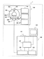
まず、図1を用いて本実施形態の医用画像診断装置の一例であるX線CT装置の全体構成を説明する。図1は、X線CT装置1の全体構成を示すブロック図である。図1に示すようにX線CT装置1は、スキャンガントリ部100と操作ユニット120とを備える。

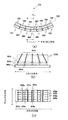
図6に、X線発生点201が第二の方向に移動し、X線発生点201Lとなったときの各検出素子203bに入射するX線の例を示す。ここで第二の方向とは、検出素子203bのX線入射面に対するX線の入射角度が、X線入射面に対するスライス方向遮蔽板202aの傾きよりも大きくなる方向とする。すなわち、図6において、X線発生点201が左側に移動する方向である。なお図6には、検出器ブロックのスライス方向左半分を図示している。また、分離部203dを位置によって区分けするため、図3と同様に、各分離部及び各検出素子に符号を付けている。
Claims (9)
- X線発生点から照射されたX線を検出し、チャンネル方向とスライス方向にそれぞれ複数配列された検出素子と、
前記検出素子をスライス方向に分離する分離部と、
前記分離部のX線入射面側に配置され、前記分離部のスライス方向の幅以上の幅を有し前記検出素子に入射するX線の一部を遮蔽するX線遮蔽体と、
前記X線遮蔽体のX線入射面側に配置され、散乱線を除去する散乱線除去コリメータと、を備えたX線検出器であって、
前記分離部は、前記X線発生点が移動する範囲において、前記X線遮蔽部あるいは前記散乱線除去コリメータによってX線の影になる位置に配置されることを特徴とするX線検出器。 - 請求項1に記載のX線検出器において、
前記X線遮蔽体のスライス方向の中心よりも、前記X線発生点から遠い位置に前記分離部が配置されることを特徴とするX線検出器。 - 請求項2に記載のX線検出器において、
SがX線発生点からスライス方向において最も離れたX線遮蔽体のX線発生点側の端部から移動前のX線発生点までの距離であり、FsがX線発生点の移動量であり、tが検出素子の厚さであり、LがX線発生点から検出素子までの距離であるとき、
前記分離部のスライス方向におけるX線発生点側端部から前記X線遮蔽体のスライス方向におけるX線発生点側端部までの距離wが
w≧(S+Fs)t/L
の範囲にあることを特徴とするX線検出器。 - 請求項2に記載のX線検出器において、
前記散乱線除去コリメータは、前記X線発生点に向かって配置される複数のスライス方向遮蔽板を有し、
前記スライス方向遮蔽板のX線入射方向における検出素子側の端部は、前記X線遮蔽体のスライス方向幅の中心よりも前記X線発生点から遠い位置に配置されることを特徴とするX線検出器。 - 請求項4に記載のX線検出器において、
SがX線発生点から最も離れたX線遮蔽体のX線発生点側の端部から移動前のX線発生点までのスライス方向の距離であり、FsがX線発生点の移動量であり、hがスライス方向遮蔽板の高さであり、LがX線発生点から検出素子までの距離であるとき、
前記スライス方向遮蔽板のスライス方向におけるX線発生点側端部から前記X線遮蔽体のスライス方向におけるX線発生点側端部までの距離wが
w≦(S−Fs)h/L
の範囲にあることを特徴とするX線検出器。 - 請求項1に記載のX線検出器において、
前記散乱線除去コリメータは、前記X線発生点に向かって配置される複数のスライス方向遮蔽板を有し、
前記スライス方向遮蔽板のX線入射方向における検出素子側の端部は、前記X線遮蔽体のスライス方向幅の中心よりも前記X線発生点から遠い位置に配置されることを特徴とするX線検出器。 - 請求項6に記載のX線検出器において、
SがX線発生点から最も離れたX線遮蔽体のX線発生点側の端部から移動前のX線発生点までのスライス方向の距離であり、FsがX線発生点の移動量であり、hがスライス方向遮蔽板の高さであり、LがX線発生点から検出素子までの距離であるとき、
前記スライス方向遮蔽板のスライス方向におけるX線発生点側端部から前記X線遮蔽体のスライス方向におけるX線発生点側端部までの距離wが
w≦(S−Fs)h/L
の範囲にあることを特徴とするX線検出器。 - 請求項1に記載のX線検出器において、
前記散乱線除去コリメータは断面形状が台形であり、台形の下底の中心と上底の中心とを結ぶ線が前記X線発生点に向かっていることを特徴とするX線検出器。 - 前記X線発生点を有するX線源と、前記X線源に対向配置され被検体を透過したX線を検出する請求項1に記載のX線検出器と、前記X線源と前記X線検出器を搭載し前記被検体の周囲を回転する回転円盤と、前記X線検出器により検出された複数角度からの透過X線量に基づき前記被検体の断層画像を再構成する画像再構成装置と、前記画像再構成装置により再構成された断層画像を表示する画像表示装置と、を備えたことを特徴とするX線CT装置。
Priority Applications (1)
| Application Number | Priority Date | Filing Date | Title |
|---|---|---|---|
| JP2011012482A JP5661486B2 (ja) | 2011-01-25 | 2011-01-25 | X線検出器及びそれを備えたx線ct装置 |
Applications Claiming Priority (1)
| Application Number | Priority Date | Filing Date | Title |
|---|---|---|---|
| JP2011012482A JP5661486B2 (ja) | 2011-01-25 | 2011-01-25 | X線検出器及びそれを備えたx線ct装置 |
Publications (3)
| Publication Number | Publication Date |
|---|---|
| JP2012152304A true JP2012152304A (ja) | 2012-08-16 |
| JP2012152304A5 JP2012152304A5 (ja) | 2014-03-06 |
| JP5661486B2 JP5661486B2 (ja) | 2015-01-28 |
Family
ID=46834719
Family Applications (1)
| Application Number | Title | Priority Date | Filing Date |
|---|---|---|---|
| JP2011012482A Expired - Fee Related JP5661486B2 (ja) | 2011-01-25 | 2011-01-25 | X線検出器及びそれを備えたx線ct装置 |
Country Status (1)
| Country | Link |
|---|---|
| JP (1) | JP5661486B2 (ja) |
Cited By (5)
| Publication number | Priority date | Publication date | Assignee | Title |
|---|---|---|---|---|
| JP2013040859A (ja) * | 2011-08-17 | 2013-02-28 | Toshiba Corp | X線検出器及びx線ct装置 |
| JP2016030215A (ja) * | 2014-07-25 | 2016-03-07 | ジーイー・メディカル・システムズ・グローバル・テクノロジー・カンパニー・エルエルシー | Ct検出器 |
| JP2016538940A (ja) * | 2014-10-01 | 2016-12-15 | コーニンクレッカ フィリップス エヌ ヴェKoninklijke Philips N.V. | 撮像装置及び方法 |
| JP2019113392A (ja) * | 2017-12-22 | 2019-07-11 | キヤノンメディカルシステムズ株式会社 | 検出器モジュール及びx線ct装置 |
| JP7379723B2 (ja) | 2020-03-04 | 2023-11-14 | プリズマティック、センサーズ、アクチボラグ | 改良型エッジ・オンx線検出器 |
Citations (3)
| Publication number | Priority date | Publication date | Assignee | Title |
|---|---|---|---|---|
| JPH05256950A (ja) * | 1992-03-13 | 1993-10-08 | Toshiba Corp | X線コンピュータトモグラフィ装置用固体検出器 |
| JPH11295430A (ja) * | 1998-04-15 | 1999-10-29 | Shimadzu Corp | Ct用固体検出器 |
| JP2000193750A (ja) * | 1998-10-20 | 2000-07-14 | Toshiba Corp | 2次元アレイ型x線検出器、x線検出器の製造方法及び2次元アレイ型x線検出器を用いたctスキャナ装置 |
-
2011
- 2011-01-25 JP JP2011012482A patent/JP5661486B2/ja not_active Expired - Fee Related
Patent Citations (3)
| Publication number | Priority date | Publication date | Assignee | Title |
|---|---|---|---|---|
| JPH05256950A (ja) * | 1992-03-13 | 1993-10-08 | Toshiba Corp | X線コンピュータトモグラフィ装置用固体検出器 |
| JPH11295430A (ja) * | 1998-04-15 | 1999-10-29 | Shimadzu Corp | Ct用固体検出器 |
| JP2000193750A (ja) * | 1998-10-20 | 2000-07-14 | Toshiba Corp | 2次元アレイ型x線検出器、x線検出器の製造方法及び2次元アレイ型x線検出器を用いたctスキャナ装置 |
Cited By (7)
| Publication number | Priority date | Publication date | Assignee | Title |
|---|---|---|---|---|
| JP2013040859A (ja) * | 2011-08-17 | 2013-02-28 | Toshiba Corp | X線検出器及びx線ct装置 |
| JP2016030215A (ja) * | 2014-07-25 | 2016-03-07 | ジーイー・メディカル・システムズ・グローバル・テクノロジー・カンパニー・エルエルシー | Ct検出器 |
| JP2016538940A (ja) * | 2014-10-01 | 2016-12-15 | コーニンクレッカ フィリップス エヌ ヴェKoninklijke Philips N.V. | 撮像装置及び方法 |
| US9782138B2 (en) | 2014-10-01 | 2017-10-10 | Koninklijke Philips N.V. | Imaging apparatus and method |
| JP2019113392A (ja) * | 2017-12-22 | 2019-07-11 | キヤノンメディカルシステムズ株式会社 | 検出器モジュール及びx線ct装置 |
| JP7058998B2 (ja) | 2017-12-22 | 2022-04-25 | キヤノンメディカルシステムズ株式会社 | 検出器モジュール及びx線ct装置 |
| JP7379723B2 (ja) | 2020-03-04 | 2023-11-14 | プリズマティック、センサーズ、アクチボラグ | 改良型エッジ・オンx線検出器 |
Also Published As
| Publication number | Publication date |
|---|---|
| JP5661486B2 (ja) | 2015-01-28 |
Similar Documents
| Publication | Publication Date | Title |
|---|---|---|
| JP5920941B2 (ja) | X線ct装置 | |
| US8761333B2 (en) | Low resolution scintillating array for CT imaging and method of implementing same | |
| US9076563B2 (en) | Anti-scatter collimators for detector systems of multi-slice X-ray computed tomography systems | |
| US8942341B2 (en) | Method of dose reduction for CT imaging and apparatus for implementing same | |
| US10045749B2 (en) | X-ray system, in particular a tomosynthesis system and a method for acquiring an image of an object | |
| JP3961468B2 (ja) | 放射線計算断層画像装置およびそれに用いる放射線検出器 | |
| JP5661486B2 (ja) | X線検出器及びそれを備えたx線ct装置 | |
| JP2013022455A (ja) | 放射線画像診断装置及び撮像方法 | |
| JP6395703B2 (ja) | 放射線検出器とそれを備えたx線ct装置 | |
| EP3835830B1 (en) | Systems and methods for estimating a focal spot motion and calculating a corresponding correction | |
| JP6523451B2 (ja) | 放射線検出器とそれを備えたx線ct装置 | |
| JP7341721B2 (ja) | 放射線検出器、及びx線ct装置 | |
| JP7058998B2 (ja) | 検出器モジュール及びx線ct装置 | |
| JP6310703B2 (ja) | 放射線検出器とそれを用いたx線ct装置 | |
| JP7467178B2 (ja) | コリメータ及びコリメータモジュール | |
| US10722196B2 (en) | Radiographic diagnosis apparatus, radiation detector and collimator | |
| JP5674424B2 (ja) | 放射線検出器とそれを備えたx線ct装置 | |
| JP2021148468A (ja) | 放射線検出器及び放射線診断装置 | |
| JP2017056141A (ja) | 放射線検出器、検出器モジュール、及び医用画像診断装置 | |
| JP2024030533A (ja) | 光子計数型のx線画像診断装置及びパイルアップ補正用の較正データの生成方法 | |
| JP2024008043A (ja) | X線ct装置、及びスキャン条件決定方法 | |
| JP2022077085A (ja) | 放射線検出器 | |
| JP2016179153A (ja) | 放射線断層撮影装置及び画像生成装置並びにプログラム |
Legal Events
| Date | Code | Title | Description |
|---|---|---|---|
| A521 | Request for written amendment filed |
Free format text: JAPANESE INTERMEDIATE CODE: A523 Effective date: 20140116 |
|
| A621 | Written request for application examination |
Free format text: JAPANESE INTERMEDIATE CODE: A621 Effective date: 20140116 |
|
| A977 | Report on retrieval |
Free format text: JAPANESE INTERMEDIATE CODE: A971007 Effective date: 20140912 |
|
| A131 | Notification of reasons for refusal |
Free format text: JAPANESE INTERMEDIATE CODE: A131 Effective date: 20140916 |
|
| A521 | Request for written amendment filed |
Free format text: JAPANESE INTERMEDIATE CODE: A523 Effective date: 20141029 |
|
| TRDD | Decision of grant or rejection written | ||
| A01 | Written decision to grant a patent or to grant a registration (utility model) |
Free format text: JAPANESE INTERMEDIATE CODE: A01 Effective date: 20141118 |
|
| A61 | First payment of annual fees (during grant procedure) |
Free format text: JAPANESE INTERMEDIATE CODE: A61 Effective date: 20141203 |
|
| R150 | Certificate of patent or registration of utility model |
Ref document number: 5661486 Country of ref document: JP Free format text: JAPANESE INTERMEDIATE CODE: R150 |
|
| S111 | Request for change of ownership or part of ownership |
Free format text: JAPANESE INTERMEDIATE CODE: R313111 |
|
| S533 | Written request for registration of change of name |
Free format text: JAPANESE INTERMEDIATE CODE: R313533 |
|
| R350 | Written notification of registration of transfer |
Free format text: JAPANESE INTERMEDIATE CODE: R350 |
|
| LAPS | Cancellation because of no payment of annual fees |