JP2012148608A - Vehicle charging apparatus - Google Patents
Vehicle charging apparatus Download PDFInfo
- Publication number
- JP2012148608A JP2012148608A JP2011007109A JP2011007109A JP2012148608A JP 2012148608 A JP2012148608 A JP 2012148608A JP 2011007109 A JP2011007109 A JP 2011007109A JP 2011007109 A JP2011007109 A JP 2011007109A JP 2012148608 A JP2012148608 A JP 2012148608A
- Authority
- JP
- Japan
- Prior art keywords
- door mirror
- door
- opening degree
- charging
- front door
- Prior art date
- Legal status (The legal status is an assumption and is not a legal conclusion. Google has not performed a legal analysis and makes no representation as to the accuracy of the status listed.)
- Granted
Links
Images


Classifications
-
- Y—GENERAL TAGGING OF NEW TECHNOLOGICAL DEVELOPMENTS; GENERAL TAGGING OF CROSS-SECTIONAL TECHNOLOGIES SPANNING OVER SEVERAL SECTIONS OF THE IPC; TECHNICAL SUBJECTS COVERED BY FORMER USPC CROSS-REFERENCE ART COLLECTIONS [XRACs] AND DIGESTS
- Y02—TECHNOLOGIES OR APPLICATIONS FOR MITIGATION OR ADAPTATION AGAINST CLIMATE CHANGE
- Y02T—CLIMATE CHANGE MITIGATION TECHNOLOGIES RELATED TO TRANSPORTATION
- Y02T10/00—Road transport of goods or passengers
- Y02T10/60—Other road transportation technologies with climate change mitigation effect
- Y02T10/70—Energy storage systems for electromobility, e.g. batteries
Landscapes
- Electric Propulsion And Braking For Vehicles (AREA)
- Rear-View Mirror Devices That Are Mounted On The Exterior Of The Vehicle (AREA)
- Arrangement Or Mounting Of Propulsion Units For Vehicles (AREA)
- Charge And Discharge Circuits For Batteries Or The Like (AREA)
Abstract
Description
本発明は、車両に搭載されたバッテリを外部電源により充電するために、該外部電源と接続された充電プラグが接続される充電口を備えた車両用充電装置に関する技術分野に属する。 The present invention belongs to a technical field related to a vehicle charging device including a charging port to which a charging plug connected to an external power source is connected in order to charge a battery mounted on the vehicle with an external power source.
電動車両等の車両には、車両走行用モータを駆動するためのバッテリが搭載されており、このバッテリを、家庭用電源等の外部電源により充電可能にしたものがある。このように外部電源によりバッテリを充電可能な車両には、その充電のための充電口が設けられており、この充電口に、外部電源と接続された充電プラグが接続されて、その接続状態で外部電源によりバッテリが充電されることになる。 Some vehicles, such as electric vehicles, are equipped with a battery for driving a vehicle driving motor, and this battery can be charged by an external power source such as a household power source. Thus, a vehicle that can be charged by an external power source is provided with a charging port for charging, and a charging plug connected to the external power source is connected to the charging port, The battery is charged by the external power source.
上記充電口の配置としては、フロントフェンダの後部(例えば、特許文献1参照)や、フロントピラーの下部(例えば、特許文献2参照)が知られている。 As the arrangement of the charging port, the rear part of the front fender (for example, see Patent Document 1) and the lower part of the front pillar (for example, see Patent Document 2) are known.
ところで、上記充電口を、車両の側部において、フロントドアとフロントフェンダとフロントピラーとにより囲まれた部位に配設するようにすれば、この部位には、略三角形状の化粧板が設けられる場合があるので、化粧板を兼ねるような、充電口を覆う蓋部材を設けても、外観上の違和感はなく、また、上記部位に対応する車体に、充電口を構成する部材が挿通される孔が形成されても、車両衝突時の車体性能への影響は殆どなく、車両の外観のデザイン性や車両衝突時の車体性能を損なうことがない。さらに、上記部位に充電口が配設されることで、車両の乗員が腰を屈めなくても略直立姿勢で充電プラグを充電口に接続することができるようになり、充電プラグのアクセス性が良好になるという利点がある。 By the way, if the charging port is disposed on a side part of the vehicle surrounded by the front door, the front fender, and the front pillar, a substantially triangular decorative plate is provided at this part. Therefore, even if a lid member that covers the charging port, which also serves as a decorative plate, is provided, there is no sense of incongruity in appearance, and a member constituting the charging port is inserted into the vehicle body corresponding to the above part. Even if the hole is formed, there is almost no influence on the vehicle body performance at the time of the vehicle collision, and the appearance design of the vehicle and the vehicle body performance at the time of the vehicle collision are not impaired. Furthermore, by providing the charging port at the above-mentioned site, it becomes possible to connect the charging plug to the charging port in a substantially upright position without the vehicle occupant bending down, making the charging plug accessible. There is an advantage of being good.
しかし、上記部位に充電口を配設した場合、フロントドアの前端近傍における充電口と略同じ高さ位置には、通常、ドアミラーが配設されており、このため、充電プラグが充電口に接続された状態にあるときに、フロントドアが開かれると、該フロントドアのドアミラーが充電プラグと干渉する可能性がある。 However, when a charging port is provided at the above location, a door mirror is usually provided at the same height as the charging port near the front end of the front door, so the charging plug is connected to the charging port. When the front door is opened in the closed state, the door mirror of the front door may interfere with the charging plug.
本発明は、斯かる点に鑑みてなされたものであり、その目的とするところは、充電口を、車両の側部において、フロントドアとフロントフェンダとフロントピラーとにより囲まれた部位に配設した場合において、充電プラグが充電口に接続された状態にあるときに、フロントドアが開かれても、そのフロントドアのドアミラーが充電プラグと干渉するのを防止しようとすることにある。 The present invention has been made in view of such a point, and an object of the present invention is to arrange a charging port at a portion surrounded by a front door, a front fender, and a front pillar on a side portion of the vehicle. In this case, even when the front door is opened when the charging plug is connected to the charging port, it is intended to prevent the door mirror of the front door from interfering with the charging plug.
上記の目的を達成するために、本発明では、車両に搭載されたバッテリを外部電源により充電するために、該外部電源と接続された充電プラグが接続される充電口を備えた車両用充電装置を対象として、上記充電口は、上記車両の側部において、フロントドアと、該フロントドアの前側に配置されたフロントフェンダと、該フロントフェンダとルーフパネルとを繋ぐように配置されたフロントピラーとにより囲まれた部位に配設され、上記フロントドアの前端近傍における上記充電口と略同じ高さ位置に、ドアミラーが配設されており、上記充電プラグの上記充電口への接続を検出する充電プラグ接続検出手段と、上記フロントドアの開度を検出する開度検出手段と、上記フロントドアの最大開度を、全開開度よりも小さい開度に規制する最大開度規制手段と、上記最大開度規制手段の作動を制御する最大開度規制制御手段とを更に備え、上記最大開度規制制御手段は、上記充電プラグ接続検出手段により上記充電プラグの上記充電口への接続が検出されたときにおいて、上記開度検出手段による上記フロントドアの検出開度が、全開開度よりも小さい所定開度以下であるときには、上記最大開度規制手段により上記フロントドアの最大開度を上記所定開度に規制するとともに、上記開度検出手段による上記フロントドアの検出開度が上記所定開度よりも大きいときには、上記最大開度規制手段により上記フロントドアの最大開度を該フロントドアの当該検出開度に規制するように構成されている、という構成とした。 In order to achieve the above object, in the present invention, in order to charge a battery mounted on a vehicle with an external power source, a vehicle charging device having a charging port to which a charging plug connected to the external power source is connected. In the vehicle, the charging port includes a front door, a front fender disposed on the front side of the front door, and a front pillar disposed so as to connect the front fender and the roof panel. The door mirror is disposed at a position substantially the same height as the charging port in the vicinity of the front end of the front door, and charging for detecting the connection of the charging plug to the charging port. Plug connection detecting means, opening degree detecting means for detecting the opening degree of the front door, and maximum opening degree of the front door being restricted to an opening degree smaller than the fully opened opening degree. An opening restriction means; and a maximum opening restriction control means for controlling the operation of the maximum opening restriction means, wherein the maximum opening restriction control means is configured to charge the charging plug with the charging plug connection detection means. When the connection to the mouth is detected and the detected opening of the front door by the opening detecting means is not more than a predetermined opening smaller than the fully opened opening, the maximum opening restricting means causes the front door to When the opening degree detected by the opening degree detection means is larger than the predetermined opening degree, the maximum opening degree restriction means causes the maximum opening degree of the front door to be maximized. It was set as the structure which is comprised so that a degree may be controlled by the said detection opening degree of this front door.
上記の構成により、所定開度を、フロントドアのドアミラーが、充電口に接続された充電プラグと干渉する開度よりも小さい開度(出来る限り大きい開度であって、各種部品の組付誤差等を考慮した、充電プラグと絶対に干渉しない開度が好ましい)に設定しておけば、充電プラグが充電口に接続されているときに、フロントドアを上記所定開度以下の開度(例えば全閉開度)から開けたとしても、フロントドアの最大開度が上記所定開度で規制されるので、フロントドアのドアミラーが充電プラグと干渉することはない。また、充電プラグが充電口に接続されたときに、フロントドアの開度が上記所定開度よりも大きい開度(通常、充電プラグと干渉する開度よりも僅かに小さい開度)である場合には、フロントドアの最大開度が、その開度に規制されるので、その開度よりも大きくすることはできず、フロントドアのドアミラーが充電プラグと干渉することはない。よって、充電プラグが充電口に接続された状態にあるときに、フロントドアが開かれても、フロントドアのドアミラーが充電プラグと干渉するのを防止することができる。 With the above configuration, the predetermined opening degree is smaller than the opening degree at which the door mirror of the front door interferes with the charging plug connected to the charging port (the opening degree is as large as possible, and the assembly error of various parts) If an opening that does not interfere with the charging plug is preferable, the opening of the front door is not more than the predetermined opening (for example, when the charging plug is connected to the charging port). Even when opened from the fully closed position, the maximum opening of the front door is regulated by the predetermined opening, so that the door mirror of the front door does not interfere with the charging plug. Further, when the charging plug is connected to the charging port, the opening degree of the front door is larger than the predetermined opening degree (usually slightly smaller than the opening degree that interferes with the charging plug). In this case, since the maximum opening of the front door is regulated by the opening, it cannot be made larger than the opening, and the door mirror of the front door does not interfere with the charging plug. Therefore, even when the front door is opened when the charging plug is connected to the charging port, the door mirror of the front door can be prevented from interfering with the charging plug.
上記車両用充電装置において、上記最大開度規制制御手段は、上記充電プラグ接続検出手段により上記充電プラグの上記充電口への接続が検出されたときにおいて、上記開度検出手段による上記フロントドアの検出開度が上記所定開度よりも大きくて、上記最大開度規制手段により上記フロントドアの最大開度を該フロントドアの当該検出開度に規制した後、上記開度検出手段による上記フロントドアの検出開度が上記所定開度以下になったときには、上記最大開度規制手段により上記フロントドアの最大開度を上記所定開度に規制するように構成されている、ことが好ましい。 In the vehicular charging apparatus, the maximum opening degree restriction control means is configured such that when the connection of the charging plug to the charging port is detected by the charging plug connection detecting means, the opening degree detecting means detects the front door of the front door. After the detected opening is larger than the predetermined opening, and the maximum opening restricting means restricts the maximum opening of the front door to the detected opening of the front door, the front door by the opening detecting means It is preferable that the maximum opening degree of the front door is restricted to the predetermined opening degree by the maximum opening degree restricting means when the detected opening degree is equal to or less than the predetermined opening degree.
このことにより、フロントドアの開度が上記所定開度よりも大きい開度にある場合でも、一旦、フロントドアの開度を上記所定開度以下にすれば、フロントドアの最大開度が上記所定開度に規制される。この結果、フロントドアのドアミラーが充電プラグと干渉するのを確実に防止することができる。 As a result, even when the opening degree of the front door is larger than the predetermined opening degree, once the opening degree of the front door is made equal to or less than the predetermined opening degree, the maximum opening degree of the front door is set to the predetermined opening degree. Regulated by opening. As a result, it is possible to reliably prevent the door mirror of the front door from interfering with the charging plug.
上記車両用充電装置において、上記ドアミラーを、格納位置と展開位置との間で相互に移動させるドアミラー駆動手段と、上記ドアミラーが上記格納位置にある状態か又は上記展開位置にある状態かを検出するドアミラー状態検出手段と、上記ドアミラー駆動手段の作動を制御するドアミラー駆動制御手段とを更に備え、上記ドアミラー駆動制御手段は、上記充電プラグ接続検出手段により上記充電プラグの上記充電口への接続が検出されたときにおいて、上記ドアミラー状態検出手段により上記ドアミラーが上記展開位置にある状態が検出されたときには、上記ドアミラー駆動手段により上記ドアミラーを上記格納位置に移動させるように構成されている、ことが好ましい。 In the vehicle charging device, door mirror driving means for moving the door mirror between a retracted position and an unfolded position, and whether the door mirror is in the retracted position or in the unfolded position are detected. The apparatus further comprises door mirror state detection means and door mirror drive control means for controlling the operation of the door mirror drive means, wherein the door mirror drive control means detects connection of the charging plug to the charging port by the charge plug connection detection means. When the door mirror state detecting means detects that the door mirror is in the unfolded position, the door mirror driving means is preferably configured to move the door mirror to the storage position. .
このことで、充電プラグが充電口に接続されたときに、フロントドアのドアミラーを格納位置にするので、上記所定開度を大きくしても、ドアミラーが充電プラグと干渉しなくなる。したがって、フロントドアのドアミラーが充電プラグと干渉するのを防止しつつ、フロントドアの最大開度の規制時に、乗員がフロントドアを大きく開けられるようにして、乗員の利便性を向上させることができる。 Thus, when the charging plug is connected to the charging port, the door mirror of the front door is set to the retracted position, so that the door mirror does not interfere with the charging plug even if the predetermined opening is increased. Therefore, while preventing the door mirror of the front door from interfering with the charging plug, when the maximum opening degree of the front door is restricted, the occupant can open the front door to improve the convenience of the occupant. .
上記車両用充電装置において、上記ドアミラーは、格納位置と展開位置との間で相互に移動可能に構成され、上記ドアミラーが上記格納位置にある状態か又は上記展開位置にある状態かを検出するドアミラー状態検出手段を更に備え、上記最大開度規制制御手段は、上記充電プラグ接続検出手段により上記充電プラグの上記充電口への接続が検出されたときにおいて、上記ドアミラー状態検出手段により上記ドアミラーが上記格納位置にある状態が検出されたときには、該ドアミラーが上記展開位置にある状態が検出されたときよりも上記所定開度を大きくするように構成されている、という構成としてもよい。 In the above vehicle charging device, the door mirror is configured to be movable between a retracted position and an unfolded position, and detects whether the door mirror is in the retracted position or the unfolded position. State detection means further comprising: the maximum opening degree restriction control means when the connection of the charging plug to the charging port is detected by the charging plug connection detection means, the door mirror state detection means causes the door mirror to be When the state in the retracted position is detected, the predetermined opening degree may be set larger than when the door mirror is in the deployed position.
こうすることで、フロントドアのドアミラーの状態に応じて、上記所定開度を適切に設定することができるようになり、ドアミラーが格納位置にあれば、フロントドアの最大開度の規制時に、乗員がフロントドアを大きく開けられるようになる。 By doing so, the predetermined opening can be appropriately set according to the state of the door mirror of the front door. If the door mirror is in the retracted position, the passenger is restricted when the maximum opening of the front door is restricted. Will be able to open the front door greatly.
また、本発明の別の構成では、車両に搭載されたバッテリを外部電源により充電するために、該外部電源と接続された充電プラグが接続される充電口を備えた車両用充電装置を対象として、上記充電口は、上記車両の側部において、フロントドアと、該フロントドアの前側に配置されたフロントフェンダと、該フロントフェンダとルーフパネルとを繋ぐように配置されたフロントピラーとにより囲まれた部位に配設されていて、上記充電プラグが、平面視で車幅方向内側に向かって車両後側に傾斜して延びた状態で、該充電口に接続されるように構成され、上記フロントドアの前端近傍における上記充電口と略同じ高さ位置に、ドアミラーが配設されており、上記充電プラグの上記充電口への接続を検出する充電プラグ接続検出手段と、上記ドアミラーを、格納位置と展開位置との間で相互に移動させるドアミラー駆動手段と、上記ドアミラーが上記格納位置にある状態か又は上記展開位置にある状態かを検出するドアミラー状態検出手段と、上記ドアミラー駆動手段の作動を制御するドアミラー駆動制御手段とを更に備え、上記ドアミラー駆動制御手段は、上記充電プラグ接続検出手段により上記充電プラグの上記充電口への接続が検出されたときにおいて、上記ドアミラー状態検出手段により上記ドアミラーが上記展開位置にある状態が検出されたときには、上記ドアミラー駆動手段により上記ドアミラーを格納位置に移動させるように構成されているものとする。 In another configuration of the present invention, in order to charge a battery mounted on a vehicle with an external power source, a vehicle charging device including a charging port to which a charging plug connected to the external power source is connected is targeted. The charging port is surrounded at the side of the vehicle by a front door, a front fender disposed on the front side of the front door, and a front pillar disposed so as to connect the front fender and the roof panel. The charging plug is configured to be connected to the charging port in a state where the charging plug is inclined and extended toward the vehicle rear side in a vehicle width direction in a plan view, and the front A door mirror is disposed at substantially the same height as the charging port in the vicinity of the front end of the door, and charging plug connection detecting means for detecting connection of the charging plug to the charging port; and Door mirror driving means for moving the mirror between the retracted position and the unfolded position; door mirror state detecting means for detecting whether the door mirror is in the retracted position or the unfolded position; and the door mirror Door mirror drive control means for controlling the operation of the drive means, the door mirror drive control means, when the connection to the charging port of the charging plug is detected by the charging plug connection detection means, the door mirror state It is assumed that the door mirror is moved to the storage position by the door mirror driving means when the detection means detects that the door mirror is in the unfolded position.
このことにより、平面視での、充電口に接続された充電プラグの車幅方向に対する傾斜と、フロントドアのドアミラーが格納位置にあることとで、フロントドアを全開にしたとしても、フロントドアのドアミラーが、充電口に接続された充電プラグと干渉するのを防止することができるようになる。これにより、フロントドアの最大開度を規制する必要がなく、構成が簡単になる。 As a result, even when the front door is fully opened, the charging plug connected to the charging port in the plan view is inclined with respect to the vehicle width direction and the door mirror of the front door is in the retracted position. It becomes possible to prevent the door mirror from interfering with the charging plug connected to the charging port. Thereby, it is not necessary to regulate the maximum opening of the front door, and the configuration is simplified.
以上説明したように、本発明の車両用充電装置によると、充電口を、車両の側部において、フロントドアとフロントフェンダとフロントピラーとにより囲まれた部位に配設した場合において、充電プラグが充電口に接続された状態にあるときに、フロントドアの最大開度が規制されるか、又は、ドアミラーが格納位置へ移動することより、開かれたフロントドアのドアミラーが充電プラグと干渉するのを防止することができる。 As described above, according to the charging device for a vehicle of the present invention, when the charging port is disposed on the side portion of the vehicle and surrounded by the front door, the front fender, and the front pillar, the charging plug is When it is connected to the charging port, the maximum opening of the front door is restricted, or the door mirror of the opened front door interferes with the charging plug because the door mirror moves to the storage position. Can be prevented.
以下、本発明の実施形態を図面に基づいて詳細に説明する。 Hereinafter, embodiments of the present invention will be described in detail with reference to the drawings.
(実施形態1)
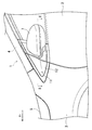
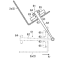
図1は、本発明の実施形態1に係る車両用充電装置を備えた電動車両1(以下、車両1ともいう)の要部を示す。図1中、2は、車両1の左側側部に設けられた左側フロントドアであり、3は、車両1の左側側部における左側フロントドア2の車両前側に配置された左側フロントフェンダであり、4は、左側フロントフェンダ3と不図示のルーフパネルとを繋ぐように配置された左側フロントピラーである。以下、車両1についての前、後、左、右、上及び下を、それぞれ単に前、後、左、右、上及び下という。また、図1〜図3及び図5〜図9において、車両1の前側を矢印Frで示す。
(Embodiment 1)
FIG. 1 shows a main part of an electric vehicle 1 (hereinafter also referred to as a vehicle 1) provided with a vehicle charging device according to Embodiment 1 of the present invention. In FIG. 1, 2 is a left front door provided on the left side of the
上記車両1は、モータによって走行するように構成されている。上記モータは、車両1の前部におけるモータルーム(内燃機関を有する車両のエンジンルームに相当する)内に配設されていて、車両1の車室フロアの下側に搭載されたバッテリ(例えばリチウムバッテリ等の二次電池)により駆動される。上記モータルームの上側は、ボンネット5によって覆われている。
The vehicle 1 is configured to run by a motor. The motor is disposed in a motor room (corresponding to an engine room of a vehicle having an internal combustion engine) at a front portion of the vehicle 1 and is mounted on a lower side of the vehicle room floor of the vehicle 1 (for example, lithium). Driven by a secondary battery such as a battery). The upper side of the motor room is covered with a
上記左側フロントフェンダ3は、上記モータルームの左側側方に位置していて、車両前端部から左側フロントドア2の直前に亘って車両前後方向に延びている。また、左側フロントピラー4は、左側フロントフェンダ3の後端上部と上記ルーフパネルの左前端部とを繋ぐように、左側フロントドア2の上縁部に沿って、車両後側に向かって上側に傾斜して延びている。
The left
上記左側フロントドア2の前端近傍(後述の充電口21と略同じ高さ位置)には、図1及び図2に示すように、左側ドアミラー7が設けられており、この左側ドアミラー7は、鏡体の反射面7a(図2参照)が車幅方向内側を向く格納位置と、該反射面7aが後側を向く展開位置(使用位置)との間で、鉛直方向に延びる軸回りに回動する電動格納式のものである。すなわち、左側ドアミラー7の内部に、左側ドアミラー7を、格納位置と展開位置との間で相互に移動させる左側ドアミラー駆動モータ52(図10にのみ示す)が設けられている。左側ドアミラー7は、車両1の乗員等が手動で格納位置又は展開位置に移動させることも可能である。図1は、左側フロントドア2が全閉とされかつ左側ドアミラー7が格納位置にある状態を示し、図2は、左側フロントドア2が全閉とされかつ左側ドアミラー7が展開位置にある状態を示す。尚、図2では、左側ドアミラー7の内部の詳細を省略している。
As shown in FIGS. 1 and 2, a
車両1の右側側部には、車両1の左側側部と同様に、右側フロントドア、右側フロントフェンダ及び右側フロントピラーが設けられており、これらの位置関係は、左側のものと同様である。また、右側フロントドア(左側フロントドア2の左側ドアミラー7と同様の位置)には、左側ドアミラー7と同様の構成の右側ドアミラーが設けられている。この右側ドアミラーは、右側ドアミラー駆動モータ53(図10にのみ示す)によって、格納位置と展開位置との間で相互に移動させられる。
The right side of the vehicle 1 is provided with a right front door, a right front fender, and a right front pillar, similar to the left side of the vehicle 1, and the positional relationship thereof is the same as that of the left side. Further, a right door mirror having the same configuration as that of the
上記車両1の左側側部において左側フロントドア2と左側フロントフェンダ3と左側フロントピラー4とにより囲まれた部位(左側ドアミラー7の前側の部位)は、車両外の外部電源により上記バッテリを充電するための充電部11とされている。上記外部電源としては、本実施形態では、100V乃至200Vの家庭用電源であるが、家庭用電源よりも高電圧の急速充電器であってもよい。
A portion surrounded by the left
上記充電部11の最外側には、後述の充電口21を覆う、開閉可能な略三角形状の蓋部材12が配設されている。この蓋部材12は、化粧板(ガーニッシュ)を兼ねており、上記バッテリへの充電を行うときにのみ、開けた状態にし、それ以外のときには、全閉状態にして、充電部11の見栄えを良好にするものである。尚、車両1の右側側部において右側フロントドアと右側フロントフェンダと右側フロントピラーとにより囲まれた部位(車両1の左側側部における充電部11と同様の部位)には、略三角形状の化粧板が固定されている。これにより、蓋部材12が全閉とされているときには、車両1の左右両側部で外観上の相違はない。
A substantially
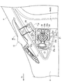
蓋部材12及び左側フロントドア2の前端部の車幅方向内側には、図2〜図4に示すように、左側フロントドア2の開閉ヒンジ部35(図6参照)を支持する左側ヒンジピラー8が配設されている。この左側ヒンジピラー8は、前後方向に延びる左側サイドシル(図示せず)の前端部から上側に延びて左側フロントピラー4の前端部に繋がる。尚、図3では、左側フロントドア2の記載を省略しているとともに、蓋部材12を開いた状態にして、左側ヒンジピラー8(後述のアウタパネル8a)が見えるようにしている。
On the inner side in the vehicle width direction of the front end portion of the
図4に示すように、左側フロントピラー4は、車両外側のアウタパネル4aと、車両内側のインナパネル4bと、アウタパネル4a及びインナパネル4b間に配設されたレインフォースメント4cとを有している。また、左側ヒンジピラー8も、車両外側のアウタパネル8aと、車両内側のインナパネル8bと、アウタパネル8a及びインナパネル8b間に配設されたレインフォースメント8cとを有している。左側フロントピラー4のアウタパネル4a、インナパネル4b及びレインフォースメント4cは、左側ヒンジピラー8のアウタパネル8a、インナパネル8b及びレインフォースメント8cとそれぞれ一体形成されている。
As shown in FIG. 4, the left
左側ヒンジピラー8のアウタパネル8aの外側の面は、左側フロントピラー4のアウタパネル4aの外側の面及び左側フロントフェンダ3の外側の面よりも車幅方向内側に位置している。そして、蓋部材12が全閉とされかつ左側フロントドア2が全閉状態にあるとき、蓋部材12の外側の面、左側フロントドア2の外側の面、左側フロントフェンダ3の外側の面、及び、左側フロントピラー4のアウタパネル4aの外側の面が、凹凸なく滑らかに繋がるようになされている。
The outer surface of the
蓋部材12は、左側フロントピラー4に開閉可能に軸支されている。具体的には、図4に示すように、蓋部材12に、支持アーム13の一端部が取付固定されており、この支持アーム13の他端部が、左側フロントピラー4のアウタパネル4aの内側の面に固定された支持部材14に支持軸15を介して回動可能に取り付けられている。左側ヒンジピラー8のアウタパネル8aには、上記支持アーム13が通過する貫通孔8dが形成されている。また、左側フロントピラー4のレインフォースメント4cと左側ヒンジピラー8のレインフォースメント8cとの境界部には、蓋部材12が全閉とされているときに支持アーム13との干渉を避けるための貫通孔8eが形成されている。
The
蓋部材12は、不図示の付勢部材(例えば、支持軸15の周囲に設けられた捩りコイルバネ)によって、開方向に回動するように付勢されている。この付勢部材による蓋部材12の回動は、例えば、支持アーム13が貫通孔8dの上縁部に当接することで規制されて、この規制状態(つまり、蓋部材12が完全に開いた状態)では、左側フロントフェンダ3の後端上部から左側フロントピラー4の下端部に亘る部分の側方に位置して、車両1の左側から見て、後側に向かって上側に傾斜して延びた状態となっている(図3及び図4参照)。そして、蓋部材12は、全閉状態にあるときには、不図示のロック機構によって閉状態にロックされるようになされている。このロックは、車両1の運転席の側方に設けられた解除レバーを乗員が操作することで解除され、この解除により蓋部材12が開状態となる。このような蓋部材12の開閉機構は、内燃機関を有する車両の燃料補給口を覆うリッドの周知の開閉機構と同様の構成である。
The
上記充電部11には、上記外部電源と電源ケーブルを介して接続された充電プラグ41(図5参照)が接続される充電口21が配設されている。すなわち、充電口21は、車両1の左側側部において左側フロントドア2と左側フロントフェンダ3と左側フロントピラー4とにより囲まれた部位に配設されていることになる。また、左側フロントドア2の前端近傍における充電口21と略同じ高さ位置に、左側ドアミラー7が配設されていることになる。
The charging
上記充電口21は、図2及び図3に示すように、絶縁性の樹脂により形成された筒状部材22を含む。この筒状部材22の外周面には、フランジ部22aが一体形成されている。筒状部材22の内側の孔は、充電プラグ41の筒状の先端部41a(図5参照)が嵌合する嵌合孔22bとされている。この嵌合孔22bの内部には、該嵌合孔22bに充電プラグ41の先端部41aが嵌合したときに、該先端部41aの内側に設けられた円筒形の端子が入り込む樹脂製の複数(5つ)のスリーブ23a〜23eが設けられている。スリーブ23a,23bには、充電プラグ41のプラス側及びマイナス側の電源端子がそれぞれ入り込み、スリーブ23cには、接地用の端子が入り込み、スリーブ23d,23eには、信号用の端子が入り込む。スリーブ23a,23b,23cの内径(外径)は、スリーブ23d,23eの内径(外径)よりも大きい。尚、図2では、スリーブ23a〜23eの記載を省略している。
As shown in FIGS. 2 and 3, the charging
各スリーブ23a〜23eの内部には、図示は省略するが、充電プラグ41の各端子にそれぞれ設けられた雌プラグと電気的に接続される雄プラグが設けられている。スリーブ23a,23b内の雄プラグには電力ケーブルがそれぞれ接続され、スリーブ23c内の雄プラグには接地ケーブルが接続され、スリーブ23d,23e内の雄プラグには、信号線が接続されている。上記接地ケーブルは、左側ヒンジピラー8のインナパネル8b等(接地された車体部材であればどこでもよい)に接続される。上記電力ケーブル及び信号線は、左側ヒンジピラー8のインナパネル8bに設けた貫通孔(図示せず)から車室内に入り込んで車室フロアまで降下した後、車室フロア上を前側に延びて、ダッシュパネルに設けた貫通孔を通って上記モータルーム内に入り込む。上記モータルーム内には、車載充電器54(図10にのみ示す)及び該車載充電器54を制御するコントローラ51(図10にのみ示す)が設けられており、これら車載充電器54及びコントローラ51に、上記電力ケーブル及び信号線がそれぞれ接続される。
Although not shown, male plugs that are electrically connected to the female plugs provided at the respective terminals of the charging
上記筒状部材22の嵌合孔22bの車幅方向外側の開口は、開閉自在な円形の中蓋25によって開放されたり閉塞されたりするようになされている。この中蓋25は、筒状部材22の外周面に回動可能に取り付けられているとともに、不図示の付勢部材によって開方向に回動するように付勢されている。一方、筒状部材22の外周面における、中蓋25の取付部分と径方向に対向する部分には、爪部材26が回動可能に取り付けられており、この爪部材26が、中蓋25に設けられた係合突起部25aと係合して、中蓋25の閉状態が保持される。爪部材26は、不図示の付勢部材によって筒状部材22の径方向内側へ回動するように付勢されている。そして、乗員が、上記バッテリを充電するべく充電プラグ41を充電口21に接続する際(つまり、筒状部材22の嵌合孔22bに充電プラグ41の先端部41aを嵌合させる際)に、爪部材26を筒状部材22の径方向外側へ押すことで、中蓋25を開状態にすることができる。また、上記バッテリへの充電が終了して充電プラグ41を充電口21から外した後において、中蓋25を閉じるときには、その閉じられる中蓋25の係合突起部25aによって爪部材26が筒状部材22の径方向外側へ回動させられ、中蓋25が完全に閉じられたときに、爪部材26が筒状部材22の径方向内側へ回動して係合突起部25aと係合した状態になる。こうして中蓋25を閉じた後に、蓋部材12を閉じることができるようになる。
The opening on the outer side in the vehicle width direction of the
図2に示すように、上記筒状部材22は、フランジ部22aにてブラケット31に取付固定され、このブラケット31は左側ヒンジピラー8のアウタパネル8aに取付固定されている。これにより、筒状部材22は、ブラケット31を介して左側ヒンジピラー8に取付固定されることになる。尚、左側ヒンジピラー8のアウタパネル8a及びレインフォースメント8cには、ブラケット31が嵌合する貫通孔8f,8gがそれぞれ形成されている。
As shown in FIG. 2, the
上記のように左側ヒンジピラー8に取付固定された筒状部材22の軸心Cは、平面視で、車幅方向内側に向かって後側に傾斜して延びている。この平面視での軸心Cの車幅方向に対する傾斜角をθとする。そして、充電プラグ41の先端部41aが筒状部材22の嵌合孔22bに嵌合した状態(充電プラグ41が充電口21に接続された状態)では、筒状の先端部41aの軸心が筒状部材22の軸心Cと一致して、充電プラグ41も、平面視で車幅方向内側に向かって後側に傾斜して延びることになる(図5参照)。すなわち、充電口21は、充電プラグ41が、平面視で車幅方向内側に向かって後側に傾斜して延びた状態で、該充電口21に接続されるように構成されている。
As described above, the axial center C of the
平面視での、充電口21に接続された充電プラグ41の車幅方向に対する傾斜角は、上記軸心Cの傾斜角θと一致する。図5は、左側フロントドア2の開度が後述の所定開度でありかつ左側ドアミラー7が展開位置にある状態を示す。本実施形態では、左側フロントドア2の開度が全開開度(100%)に近い開度にされたときに、展開位置にある左側ドアミラー7が、充電口21に接続された充電プラグ41と干渉するので、この干渉を防止するために、左側フロントドア2の最大開度を、最大開度規制手段としての最大開度規制機構61によって、全開開度よりも小さい開度に規制する。尚、図5の左側ドアミラー7について二点鎖線で示す状態は、図2と同じ状態(左側フロントドアが全閉とされたときにおいて左側ドアミラーが展開位置にある状態)である。
The inclination angle of the charging
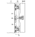
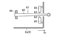
ここで、上記最大開度規制機構61について説明する。すなわち、図6及び図7に示すように、最大開度規制機構61は、水平方向に延びかつ長手方向一端部側から他端部側に向かって幅が大きくなるように両側面が傾斜した細長形状のプレート62と、2つのストッパー63とを有している。
Here, the maximum
上記プレート62の上記一端部は、左側ヒンジピラー8のインナパネル8bに対して、鉛直方向に延びる軸回りに回動可能に支持されている。このプレート62は、左側フロントドア2のインナパネル2aを貫通して、上記他端部側が、左側フロントドア2の内部に挿入されている。また、プレート62の上記他端部は、左側フロントドア2(インナパネル2a)に対して、プレート62の長手方向に相対移動可能なように、取付部材64を介して取り付けられている。図7に示すように、左側フロントドア2が全閉状態にあるときには、プレート62の上記一端部及びその近傍部のみが左側フロントドア2の外側に位置し、それ以外の部分が左側フロントドア2の内部に挿入されている。そして、左側フロントドア2を開くに連れて(左側フロントドア2の開度を大きくするに連れて)、プレート62における左側フロントドア2の外側に位置する部分の長さが長くなり、左側フロントドア2の全開状態では、図8に示すように、プレート62の上記他端部及びその近傍部のみが左側フロントドア2の内部に位置する。すなわち、左側フロントドア2の全閉状態からの、プレート62の左側フロントドア2に対する相対移動量は、左側フロントドア2の開度に対応している。
The one end of the
上記2つのストッパー63は、プレート62の幅方向両側に位置して、プレート62の傾斜した両側面にそれぞれ当接することで、プレート62の左側フロントドア2に対する相対移動を規制するものである。2つのストッパー63は、例えば電磁石等で構成されたストッパー駆動アクチュエータ65によってそれぞれ駆動されて、プレート62の両側面に対して進出及び後退移動する。図9に示すように、2つのストッパー63が進出移動してプレート62の両側面に当接した状態では、プレート62の両側面の傾斜によって、プレート62が左側フロントドア2に対して外側へ移動することはできない(つまり、左側フロントドア2をそれ以上開けることはできない)が、プレート62が左側フロントドア2に対して内部側へ移動する(つまり、左側フロントドア2を閉める)ことは可能である。また、左側フロントドア2を閉めた後、図9の状態に戻すことも可能である。これにより、左側フロントドア2の最大開度を規制することが可能になる。
The two
ストッパー63がプレート62に対して最も後退した位置にあるときには、ストッパー63がプレート62の両側面の長手方向のいずれの部分にも当接することはなく、左側フロントドア2の最大開度の規制が解除された状態になり、左側フロントドア2を全開にすることができるようになる。
When the
ストッパー63の進出位置(最も後退した位置からの進出量)は、ストッパー駆動アクチュエータ65への通電状態によって調整可能になっている。このストッパー63の進出位置の調整によって、プレート62の両側面の長手方向においてストッパー63が当接する位置を変更することができ、この変更により、左側フロントドア2の最大開度を任意に変更することが可能である。すなわち、ストッパー63の上記進出量が大きいほど、左側フロントドア2の最大開度は小さくなる。
The advancement position of the stopper 63 (the advancement amount from the most retracted position) can be adjusted by the energization state of the
上記コントローラ51は、周知のマイクロコンピュータをベースとする制御装置であって、プログラムを実行する中央算出処理装置(CPU)と、例えばRAMやROMにより構成されてプログラムおよびデータを格納するメモリと、種々の信号の入出力を行うための入出力(I/O)バスとを含む。
The
図10に示すように、コントローラ51は、上記の如く信号線を介して充電口21(スリーブ23d,23e内の雄プラグ)と接続されているとともに、車両1の乗員が操作するドアミラー格納展開スイッチ45、左側フロントドア2の開度を検出する開度検出手段としての開度検出センサ46、左側ドアミラー7が格納位置にある状態か又は展開位置にある状態かを検出する左側ドアミラーセンサ47(ドアミラー状態検出手段に相当する)、及び、右側ドアミラーが格納位置にある状態か又は展開位置にある状態かを検出する右側ドアミラーセンサ48と接続されている。
As shown in FIG. 10, the
上記開度検出センサ46は、例えば、左側フロントドア2の全閉状態からの、プレート62の左側フロントドア2に対する相対移動量を検出して、左側フロントドア2の開度を検出する。或いは、開度検出センサ46は、左側フロントドア2の開閉ヒンジ部35に設けられて、左側フロントドア2の回動角度を検出して、左側フロントドア2の開度を検出する。
The opening
また、コントローラ51は、左側ドアミラー駆動モータ52、右側ドアミラー駆動モータ53、車載充電器54及びストッパー駆動アクチュエータ65と接続されていて、これらの作動をそれぞれ制御する。すなわち、コントローラ51は、最大開度規制手段に相当する最大開度規制機構61(ストッパー駆動アクチュエータ65)の作動を制御する最大開度規制制御手段を構成するとともに、ドアミラー駆動手段に相当する左側ドアミラー駆動モータ52の作動を制御するドアミラー駆動制御手段をも構成する。
The
具体的に、コントローラ51は、乗員の操作によるドアミラー格納展開スイッチ45の状態、及び、左側及び右側ドアミラーセンサ47,48による検出状態に応じて、左側及び右側ドアミラー駆動モータ52,53によって、左側ドアミラー7及び右側ドアミラーを共に、格納位置又は展開位置に移動させる。
Specifically, the
充電口21に充電プラグ41が接続されたときには、充電プラグ41の信号用の端子とスリーブ23d,23e内の雄プラグとが接続されて、これにより、コントローラ51には、充電プラグ41から上記信号線を介して信号が入力され、この信号により、コントローラ51は、充電プラグ41が充電口21に接続されたことを検出できるようになっている。このことで、充電口21(上記雄プラグ)が、充電プラグ41の充電口21への接続を検出する充電プラグ接続検出手段を構成することになる。
When the charging
そして、コントローラ51は、充電プラグ41の充電口21への接続を検出したときに、上記車載充電器54に充電指令信号を送信して上記バッテリを充電させる。これにより、車載充電器54は、充電プラグ41及び上記電力ケーブルを介して入力した上記外部電源からの電力を、上記バッテリの充電に適した電圧になるように昇圧して、該バッテリを充電する。
When the
また、コントローラ51は、充電プラグ41の充電口21への接続を検出したときにおいて、開度検出センサ46による左側フロントドア2の検出開度が、全開開度よりも小さい所定開度以下であるときには、最大開度規制機構61のストッパー駆動アクチュエータ65によるストッパー63の進出及び進出位置の調整によって、左側フロントドア2の最大開度を上記所定開度に規制するとともに、開度検出センサ46による左側フロントドア2の検出開度が上記所定開度よりも大きいときには、左側フロントドア2の最大開度を該左側フロントドア2の当該検出開度に規制する。本実施形態では、上記所定開度は、展開位置にある左側ドアミラー7が、充電口21に接続された充電プラグ41と干渉する開度よりも小さい開度(出来る限り大きい開度であって、各種部品の組付誤差等を考慮した、充電プラグ41と絶対に干渉しない開度)に設定される。
Further, when the
上記コントローラ51の制御により、充電プラグ41が充電口21に接続されているときに、左側フロントドア2を上記所定開度以下の開度(例えば全閉開度(0%))から開けたとしても、左側フロントドア2の最大開度が上記所定開度で規制されるので、展開位置にある左側ドアミラー7が、充電口21に接続された充電プラグ41と干渉することはない。
Under the control of the
また、充電プラグ41が充電口21に接続されたときに、左側フロントドア2の開度が上記所定開度よりも大きい開度である場合、充電プラグ41を充電口21に接続できたのであるから、左側フロントドア2の開度は、充電プラグ41と干渉する開度よりも僅かに小さい開度(干渉するかしないかのぎりぎりの開度)にあることになる。この場合、充電プラグ41と干渉する開度よりも僅かに小さい開度に規制されるので、該開度よりも大きくすることはできず、左側ドアミラー7が充電プラグ41と干渉することはない。
Further, when the opening of the left
しかし、充電プラグ41と干渉する開度よりも僅かに小さい開度では、左側フロントドア2に、何等かの力が加われば干渉する可能性もある。そこで、本実施形態では、コントローラ51は、充電プラグ41の充電口21への接続を検出したときにおいて、開度検出センサ46による左側フロントドア2の検出開度が上記所定開度よりも大きくて、左側フロントドア2の最大開度を該左側フロントドア2の当該検出開度に規制した後、開度検出センサ46による左側フロントドア2の検出開度が上記所定開度以下になったときには、左側フロントドア2の最大開度を上記所定開度に規制する。これにより、左側フロントドア2の開度が上記所定開度よりも大きい開度であっても、左側フロントドア2を或る程度閉める方向に動して、その開度を上記所定開度以下にすれば、それ以降は、左側フロントドア2の最大開度が上記所定開度に規制されて、左側ドアミラー7が充電プラグ41と干渉するのを確実に防止することができるようになる。
However, at an opening that is slightly smaller than the opening that interferes with the charging
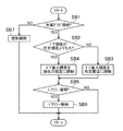
上記コントローラ51における左側フロントドア2の最大開度規制に関する制御動作について、図11のフローチャートにより説明する。
A control operation relating to the maximum opening restriction of the left
最初のステップSA1で、充電プラグ41が充電口21に接続されているか否かを判定し、このステップSA1の判定がYESであるときには、ステップSA2に進む。
In the first step SA1, it is determined whether or not the charging
ステップSA2では、左側フロントドア2の開度(開度検出センサ46による検出開度)が上記所定開度よりも大きいか否かを判定し、このステップSA2の判定がNOであるときには、ステップSA3に進んで、左側フロントドア2の最大開度を上記所定開度に規制して、しかる後にリターンする。一方、ステップSA2の判定がYESであるときには、ステップSA4に進んで、左側フロントドア2の最大開度を現在の開度(上記検出開度)に規制して、しかる後にリターンする。
In step SA2, it is determined whether or not the opening degree of the left front door 2 (the opening degree detected by the opening degree detection sensor 46) is larger than the predetermined opening degree. If the determination in step SA2 is NO, step SA3 is determined. Then, the maximum opening of the left
上記ステップSA1の判定がNOであるとき(充電プラグ41が充電口21に接続されていないとき)には、ステップSA5に進んで、左側フロントドア2の最大開度の規制を解除した状態(つまり、左側フロントドア2を全開まで開けることが可能な状態)にして、しかる後にリターンする。
When the determination in step SA1 is NO (when the charging
したがって、本実施形態では、充電プラグ41が充電口21に接続された状態にあるときに、左側フロントドア2が開かれても、展開位置にある左側ドアミラー7が充電プラグ41と干渉するのを防止することができる。
Therefore, in this embodiment, when the charging
尚、上記実施形態1においては、充電プラグ41が充電口21に接続されたときに、左側フロントドア2を所定開度まで自由に開けることは可能であるが、左側フロントドア2が全閉であるときには、左側フロントドア2のドアロックアクチュエータを作動させて左側フロントドア2をロック状態にして、左側フロントドア2が出来る限り開けられないようにしてもよい。この場合、コントローラ51が、図11のフローチャートのステップSA3又はSA4の後でかつリターンする前に、左側フロントドア2が全閉であるか否かを判定し、全閉であれば、上記ドアロックアクチュエータを作動させて左側フロントドア2をロック状態にしてリターンし、全閉でなければ、そのままリターンする。このように左側フロントドア2をロックすることについては、後述の実施形態2〜4にも適用可能である。
In the first embodiment, when the charging
(実施形態2)
図12は、本発明の実施形態2を示し、コントローラ51が、充電プラグ41の充電口21への接続を検出したときにおいて、左側ドアミラー7が展開位置にある状態が検出されたときには、左側ドアミラー7を格納位置に移動させるようにしたものである。
(Embodiment 2)
FIG. 12 shows
本実施形態では、ハード構成は上記実施形態1と同じであるが、充電プラグ41の充電口21への接続時におけるコントローラ51の制御動作が上記実施形態1とは異なる。
In the present embodiment, the hardware configuration is the same as that in the first embodiment, but the control operation of the
図12を参照して、ステップSB1〜SB4では、上記実施形態1におけるステップSA1〜SA4とそれぞれ同じ動作を実行する。そして、ステップSB3又はSB4に続くステップSB5で、左側ドアミラーセンサ47により左側ドアミラー7が展開位置にある状態か否かを判定する。このステップSB5の判定がNOであるときには、そのままリターンする一方、ステップSB5の判定がYESであるときには、ステップSB6に進んで、左側ドアミラー駆動モータ52により左側ドアミラー7を格納位置に移動させ、しかる後にリターンする。
Referring to FIG. 12, in steps SB1 to SB4, the same operations as in steps SA1 to SA4 in the first embodiment are performed. Then, in step SB5 following step SB3 or SB4, the left
上記ステップSB6では、左側ドアミラー7のみを格納位置に移動させ、右側ドアミラーは展開位置のままにするが、両ドアミラーを格納位置に移動させるようにしてもよい。尚、コントローラ51は、充電口21に充電プラグ41が接続されていることが検出されている間は、ドアミラー格納展開スイッチ45の操作は受け付けない。但し、左側ドアミラー7が格納位置に移動した後に、車両1の乗員等が手動で格納位置から展開位置に移動することがあり、そのときには、その直後のステップSB6で、左側ドアミラー7が再び格納位置に移動させられる。
In step SB6, only the
上記ステップSB1の判定がNOであるとき(充電プラグ41が充電口21に接続されていないとき)には、ステップSB7に進んで、左側フロントドア2の最大開度の規制を解除した状態にして、しかる後にリターンする。
When the determination in step SB1 is NO (when the charging
ここで、コントローラ51は、充電プラグ41の充電口21への接続を検出したときに、左側ドアミラー7が展開位置にある状態であったときには、上記規制を解除したときに、左側ドアミラー7を展開位置に移動させて元の状態に戻し、この戻し完了時に、ドアミラー格納展開スイッチ45の操作を受け付ける。
Here, when the
したがって、本実施形態では、充電プラグ41が充電口21に接続されたときに、左側ドアミラー7が常に格納位置にある状態になるので、その左側ドアミラー7が、充電口21に接続された充電プラグ41と干渉する開度は、上記実施形態1よりも大きくなる。本実施形態では、これに対応して、所定開度を、上記実施形態1よりも大きくしている。この結果、左側ドアミラー7が充電プラグ41と干渉するのを防止しつつ、左側フロントドア2の最大開度の規制時に、乗員が左側フロントドア2をより大きく開けることができるようになり、乗員の利便性を向上させることができる。
Therefore, in the present embodiment, when the charging
尚、上記実施形態2において、充電プラグ41が充電口21に接続されたときに、左側ドアミラー7が常に格納位置にある状態にされるが、この格納位置で左側ドアミラー7をロックするドアミラーロックアクチュエータを設けるようにしてもよい。この場合、コントローラ51が、図12のフローチャートにおけるステップSB5の判定がNOであるときのリターンする前、又は、ステップSB6の後でかつリターンする前に、上記ドアミラーロックアクチュエータを作動させて左側ドアミラー7を格納位置にロックする。こうすれば、左側ドアミラー7が手動でも動かなくなり、左側ドアミラー7が誤って展開位置に移動して充電プラグ41と干渉するのを防止することができる。
In the second embodiment, when the charging
(実施形態3)
図13は、本発明の実施形態3を示し、コントローラ51が、充電プラグ41の充電口21への接続を検出したときにおいて、左側ドアミラー7が展開位置にある状態が検出されたときには、左側ドアミラー7が展開位置にある状態が検出されたときよりも上記所定開度を大きくするようにしたものである。
(Embodiment 3)
FIG. 13 shows
本実施形態では、ハード構成は上記実施形態1及び2と同じであるが、充電プラグ41の充電口21への接続時におけるコントローラ51の制御動作が上記実施形態1及び2とは異なる。
In this embodiment, the hardware configuration is the same as in the first and second embodiments, but the control operation of the
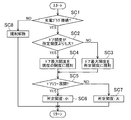
図13を参照して、ステップSC1〜SC4では、上記実施形態1におけるステップSA1〜SA4とそれぞれ同じ動作を実行する。そして、ステップSC3又はSC4に続くステップSC5で、左側ドアミラーセンサ47により左側ドアミラー7が展開位置にある状態か否かを判定する。このステップSC5の判定がYESであるときには、ステップSC6に進んで、所定開度を「小」に設定し、しかる後にリターンする。一方、ステップSC5の判定がNOであるときには、ステップSC7に進んで、所定開度を「大」に設定し、しかる後にリターンする。「小」の所定開度の大きさは、上記実施形態1と同レベルであり、「大」の所定開度の大きさは、「小」の所定開度よりも大きくて、上記実施形態2と同レベルである。
Referring to FIG. 13, in steps SC1 to SC4, the same operations as in steps SA1 to SA4 in the first embodiment are performed. In step SC5 following step SC3 or SC4, the left
したがって、本実施形態では、充電プラグ41が充電口21に接続されたときに、左側ドアミラー7が格納位置にあれば、展開位置にあるときよりも所定開度が大きくされ、フロントドアの最大開度の規制時に、乗員が左側フロントドア2を大きく開けられるようになる。
Therefore, in the present embodiment, when the
尚、上記実施形態3では、左側ドアミラー7及び右側ドアミラーは、上記実施形態1及び2と同様に、電動格納式のものであるが、これに代えて、車両1の乗員等が手動のみで格納したり展開したりできるものであってもよい。
In the third embodiment, the
また、上記実施形態1〜3では、充電口21の筒状部材22の軸心Cが、平面視で、車幅方向内側に向かって後側に傾斜して延びているが、軸心Cが平面視で車幅方向に延びる(傾斜角θ=0となる)ようにしてもよい。この場合、充電口21に接続された充電プラグ41も、平面視で車幅方向に延びて、左側フロントドア2の開度が比較的小さい段階で、左側ドアミラー7が充電プラグ41と干渉することになるが、所定開度を適切に設定することで、その干渉を防止することができる。但し、所定開度を出来る限り大きくする観点からは、軸心Cを、平面視で、車幅方向内側に向かって後側に傾斜して延びるようにすることが好ましい。
Moreover, in the said Embodiment 1-3, although the axial center C of the
(実施形態4)
図14は、本発明の実施形態4を示し、本実施形態では、上記実施形態1〜3のような最大開度規制機構61及び開度検出センサ46は存在しない。それ以外のハード構成は、上記実施形態1〜3と同じである。
(Embodiment 4)
FIG. 14 shows
本実施形態では、充電口21の筒状部材22の軸心Cが、平面視で、車幅方向内側に向かって後側に傾斜して延びており、その傾斜角θは、左側ドアミラー7が格納位置にある状態であれば、左側フロントドア2を全開にしたとしても、左側ドアミラー7が、充電口21に接続された充電プラグ41に当接しないような角度に設定されている。
In the present embodiment, the axial center C of the
そして、コントローラ51は、充電プラグ41の充電口21への接続が検出されたときにおいて、左側ドアミラーセンサ47により左側ドアミラー7が展開位置にある状態が検出されたときには、左側ドアミラー駆動モータ52により左側ドアミラー7を格納位置に移動させる。
When the left
すなわち、図14を参照して、ステップSD1で、充電プラグ41が充電口21に接続されているか否かを判定し、このステップSD1の判定がNOであるときには、そのままリターンする一方、ステップSD1の判定がYESであるときには、ステップSD2に進んで、左側ドアミラーセンサ47により左側ドアミラー7が展開位置にある状態か否かを判定する。このステップSD2の判定がNOであるときには、そのままリターンする一方、ステップSD2の判定がYESであるときには、ステップSD3に進んで、左側ドアミラー駆動モータ52により左側ドアミラー7を格納位置に移動させ、しかる後にリターンする。
That is, referring to FIG. 14, it is determined in step SD1 whether or not charging
したがって、本実施形態では、左側ドアミラー7を格納位置に移動させるだけで、左側ドアミラー7が充電プラグ41と干渉するのを防止することができ、上記実施形態1〜3のような最大開度規制機構61を設けなくても済む。この結果、上記実施形態1〜3に比べて、構成を簡略化することができる。
Therefore, in this embodiment, it is possible to prevent the
尚、上記実施形態では、左側ドアミラー7が展開位置にある状態では、左側フロントドア2を全開にしたときに、左側ドアミラー7が充電プラグ41と干渉することになるが、上記傾斜角θが、全開にされた左側フロントドア2の左側ドアミラー7が、格納位置に限らず、展開位置にあっても、充電口21に接続された充電プラグ41に当接しないような角度に設定されていてもよい。この場合でも、より確実に干渉を防止するために、上記のように左側ドアミラー7を格納位置に移動させるようにすることが好ましい。
In the above embodiment, when the
本発明は、上記実施形態1〜4に限られるものではなく、請求の範囲の主旨を逸脱しない範囲で代用が可能である。 The present invention is not limited to the first to fourth embodiments, and can be substituted without departing from the spirit of the claims.
例えば、上記実施形態1〜4では、充電口21を、車両1の左側側部において左側フロントドア2と左側フロントフェンダ3と左側フロントピラー4とにより囲まれた部位に配設したが、充電口21を、車両1の右側側部において右側フロントドアと右側フロントフェンダと右側フロントピラーとにより囲まれた部位に配設してもよく、車両1の左右両側に配設してもよい。充電口21を車両1の左右両側に配設した場合、車両1の乗員は、その両側の充電口21のうち、充電プラグ41を接続し易い充電口21を選択することができ、車両1をバッテリ充電のために停止したときの車両1の向きの自由度が増大する。そして、充電プラグ41が接続された充電口21に対応する側のフロントドアの最大開度を規制したり、そのフロントドアのドアミラーを格納位置に移動させたりするようにすればよい。
For example, in Embodiments 1 to 4 described above, the charging
また、上記実施形態では、本発明を電動車両1に適用した例を示したが、これに限らず、例えばプラグインハイブリッド車両に本発明を適用してもよい。 Moreover, although the example which applied this invention to the electric vehicle 1 was shown in the said embodiment, you may apply this invention not only to this but a plug-in hybrid vehicle, for example.
上記実施形態は単なる例示に過ぎず、本発明の範囲を限定的に解釈してはならない。本発明の範囲は請求の範囲によって定義され、請求の範囲の均等範囲に属する変形や変更は、全て本発明の範囲内のものである。 The above embodiments are merely examples, and the scope of the present invention should not be construed in a limited manner. The scope of the present invention is defined by the scope of the claims, and all modifications and changes belonging to the equivalent scope of the claims are within the scope of the present invention.
本発明は、車両に搭載されたバッテリを外部電源により充電するために、該外部電源と接続された充電プラグが接続される充電口を備えた車両用充電装置に有用である。 INDUSTRIAL APPLICABILITY The present invention is useful for a vehicle charging device including a charging port to which a charging plug connected to an external power source is connected in order to charge a battery mounted on the vehicle with an external power source.
1 車両
2 左側フロントドア
3 左側フロントフェンダ
4 左側フロントピラー
7 左側ドアミラー
11 充電部
21 充電口(充電プラグ接続検出手段)
41 充電プラグ
46 開度検出センサ(開度検出手段)
47 左側ドアミラーセンサ(ドアミラー状態検出手段)
51 コントローラ(最大開度規制制御手段)(ドアミラー駆動制御手段)
52 左側ドアミラー駆動モータ(ドアミラー駆動手段)
61 最大開度規制機構(最大開度規制手段)
1
41
47 Left side door mirror sensor (door mirror state detection means)
51 controller (maximum opening degree restriction control means) (door mirror drive control means)
52 Left door mirror drive motor (door mirror drive means)
61 Maximum opening restriction mechanism (maximum opening restriction means)
Claims (5)
上記充電口は、上記車両の側部において、フロントドアと、該フロントドアの前側に配置されたフロントフェンダと、該フロントフェンダとルーフパネルとを繋ぐように配置されたフロントピラーとにより囲まれた部位に配設され、
上記フロントドアの前端近傍における上記充電口と略同じ高さ位置に、ドアミラーが配設されており、
上記充電プラグの上記充電口への接続を検出する充電プラグ接続検出手段と、
上記フロントドアの開度を検出する開度検出手段と、
上記フロントドアの最大開度を、全開開度よりも小さい開度に規制する最大開度規制手段と、
上記最大開度規制手段の作動を制御する最大開度規制制御手段とを更に備え、
上記最大開度規制制御手段は、上記充電プラグ接続検出手段により上記充電プラグの上記充電口への接続が検出されたときにおいて、上記開度検出手段による上記フロントドアの検出開度が、全開開度よりも小さい所定開度以下であるときには、上記最大開度規制手段により上記フロントドアの最大開度を上記所定開度に規制するとともに、上記開度検出手段による上記フロントドアの検出開度が上記所定開度よりも大きいときには、上記最大開度規制手段により上記フロントドアの最大開度を該フロントドアの当該検出開度に規制するように構成されていることを特徴とする車両用充電装置。 A charging device for a vehicle including a charging port to which a charging plug connected to the external power source is connected in order to charge a battery mounted on the vehicle with an external power source,
The charging port is surrounded at the side of the vehicle by a front door, a front fender disposed on the front side of the front door, and a front pillar disposed so as to connect the front fender and the roof panel. Arranged in the site,
A door mirror is disposed at the same height as the charging port in the vicinity of the front end of the front door,
Charging plug connection detecting means for detecting connection of the charging plug to the charging port;
Opening detection means for detecting the opening of the front door;
Maximum opening restriction means for restricting the maximum opening of the front door to an opening smaller than the fully opened opening;
A maximum opening restriction control means for controlling the operation of the maximum opening restriction means;
The maximum opening degree restricting control means is configured such that when the charging plug connection detecting means detects the connection of the charging plug to the charging port, the opening degree of the front door detected by the opening degree detecting means is fully opened. When the opening degree is equal to or smaller than a predetermined opening degree, the maximum opening degree restricting means restricts the maximum opening degree of the front door to the predetermined opening degree, and the opening degree detected by the opening degree detecting means When the opening is larger than the predetermined opening, the vehicle charging device is configured to restrict the maximum opening of the front door to the detected opening of the front door by the maximum opening restriction means. .
上記最大開度規制制御手段は、上記充電プラグ接続検出手段により上記充電プラグの上記充電口への接続が検出されたときにおいて、上記開度検出手段による上記フロントドアの検出開度が上記所定開度よりも大きくて、上記最大開度規制手段により上記フロントドアの最大開度を該フロントドアの当該検出開度に規制した後、上記開度検出手段による上記フロントドアの検出開度が上記所定開度以下になったときには、上記最大開度規制手段により上記フロントドアの最大開度を上記所定開度に規制するように構成されていることを特徴とする車両用充電装置。 The vehicle charging device according to claim 1,
The maximum opening degree restriction control means detects the opening degree of the front door detected by the opening degree detecting means when the connection of the charging plug to the charging port is detected by the charging plug connection detecting means. The maximum opening degree of the front door is restricted to the detected opening degree of the front door by the maximum opening degree regulating means, and the detected opening degree of the front door by the opening degree detecting means is the predetermined opening degree. A charging device for a vehicle, wherein the maximum opening degree of the front door is restricted to the predetermined opening degree by the maximum opening degree restriction means when the opening degree is equal to or less than the opening degree.
上記ドアミラーを、格納位置と展開位置との間で相互に移動させるドアミラー駆動手段と、
上記ドアミラーが上記格納位置にある状態か又は上記展開位置にある状態かを検出するドアミラー状態検出手段と、
上記ドアミラー駆動手段の作動を制御するドアミラー駆動制御手段とを更に備え、
上記ドアミラー駆動制御手段は、上記充電プラグ接続検出手段により上記充電プラグの上記充電口への接続が検出されたときにおいて、上記ドアミラー状態検出手段により上記ドアミラーが上記展開位置にある状態が検出されたときには、上記ドアミラー駆動手段により上記ドアミラーを上記格納位置に移動させるように構成されていることを特徴とする車両用充電装置。 The vehicle charging device according to claim 1 or 2,
Door mirror driving means for moving the door mirror between a retracted position and a deployed position;
Door mirror state detection means for detecting whether the door mirror is in the retracted position or in the unfolded position;
Door mirror drive control means for controlling the operation of the door mirror drive means,
In the door mirror drive control means, when the connection of the charging plug to the charging port is detected by the charging plug connection detecting means, the door mirror state detecting means detects that the door mirror is in the unfolded position. In some cases, the vehicle charging apparatus is configured to move the door mirror to the storage position by the door mirror driving means.
上記ドアミラーは、格納位置と展開位置との間で相互に移動可能に構成され、
上記ドアミラーが上記格納位置にある状態か又は上記展開位置にある状態かを検出するドアミラー状態検出手段を更に備え、
上記最大開度規制制御手段は、上記充電プラグ接続検出手段により上記充電プラグの上記充電口への接続が検出されたときにおいて、上記ドアミラー状態検出手段により上記ドアミラーが上記格納位置にある状態が検出されたときには、該ドアミラーが上記展開位置にある状態が検出されたときよりも上記所定開度を大きくするように構成されていることを特徴とする車両用充電装置。 The vehicle charging device according to claim 1 or 2,
The door mirror is configured to be movable between a retracted position and a deployed position,
Door mirror state detection means for detecting whether the door mirror is in the retracted position or in the unfolded position;
The maximum opening degree restricting control means detects a state in which the door mirror is in the retracted position by the door mirror state detecting means when the connection of the charging plug to the charging port is detected by the charging plug connection detecting means. When this is done, the vehicle charging device is configured to make the predetermined opening larger than when the state in which the door mirror is in the deployed position is detected.
上記充電口は、上記車両の側部において、フロントドアと、該フロントドアの前側に配置されたフロントフェンダと、該フロントフェンダとルーフパネルとを繋ぐように配置されたフロントピラーとにより囲まれた部位に配設されていて、上記充電プラグが、平面視で車幅方向内側に向かって車両後側に傾斜して延びた状態で、該充電口に接続されるように構成され、
上記フロントドアの前端近傍における上記充電口と略同じ高さ位置に、ドアミラーが配設されており、
上記充電プラグの上記充電口への接続を検出する充電プラグ接続検出手段と、
上記ドアミラーを、格納位置と展開位置との間で相互に移動させるドアミラー駆動手段と、
上記ドアミラーが上記格納位置にある状態か又は上記展開位置にある状態かを検出するドアミラー状態検出手段と、
上記ドアミラー駆動手段の作動を制御するドアミラー駆動制御手段とを更に備え、
上記ドアミラー駆動制御手段は、上記充電プラグ接続検出手段により上記充電プラグの上記充電口への接続が検出されたときにおいて、上記ドアミラー状態検出手段により上記ドアミラーが上記展開位置にある状態が検出されたときには、上記ドアミラー駆動手段により上記ドアミラーを格納位置に移動させるように構成されていることを特徴とする車両用充電装置。 A charging device for a vehicle including a charging port to which a charging plug connected to the external power source is connected in order to charge a battery mounted on the vehicle with an external power source,
The charging port is surrounded at the side of the vehicle by a front door, a front fender disposed on the front side of the front door, and a front pillar disposed so as to connect the front fender and the roof panel. The charging plug is configured to be connected to the charging port in a state where the charging plug is inclined and extended toward the vehicle rear side in the vehicle width direction in a plan view,
A door mirror is disposed at the same height as the charging port in the vicinity of the front end of the front door,
Charging plug connection detecting means for detecting connection of the charging plug to the charging port;
Door mirror driving means for moving the door mirror between a retracted position and a deployed position;
Door mirror state detection means for detecting whether the door mirror is in the retracted position or in the unfolded position;
Door mirror drive control means for controlling the operation of the door mirror drive means,
In the door mirror drive control means, when the connection of the charging plug to the charging port is detected by the charging plug connection detecting means, the door mirror state detecting means detects that the door mirror is in the unfolded position. In some cases, the vehicle charging apparatus is configured to move the door mirror to a storage position by the door mirror driving means.
Priority Applications (1)
| Application Number | Priority Date | Filing Date | Title |
|---|---|---|---|
| JP2011007109A JP5655581B2 (en) | 2011-01-17 | 2011-01-17 | Vehicle charging device |
Applications Claiming Priority (1)
| Application Number | Priority Date | Filing Date | Title |
|---|---|---|---|
| JP2011007109A JP5655581B2 (en) | 2011-01-17 | 2011-01-17 | Vehicle charging device |
Publications (2)
| Publication Number | Publication Date |
|---|---|
| JP2012148608A true JP2012148608A (en) | 2012-08-09 |
| JP5655581B2 JP5655581B2 (en) | 2015-01-21 |
Family
ID=46791340
Family Applications (1)
| Application Number | Title | Priority Date | Filing Date |
|---|---|---|---|
| JP2011007109A Active JP5655581B2 (en) | 2011-01-17 | 2011-01-17 | Vehicle charging device |
Country Status (1)
| Country | Link |
|---|---|
| JP (1) | JP5655581B2 (en) |
Cited By (2)
| Publication number | Priority date | Publication date | Assignee | Title |
|---|---|---|---|---|
| JP2016089399A (en) * | 2014-10-31 | 2016-05-23 | アイシン精機株式会社 | Door check mechanism and vehicle door opening retaining device |
| JP2017081184A (en) * | 2015-10-22 | 2017-05-18 | 本田技研工業株式会社 | Connector attachment structure for electric vehicle |
Citations (6)
| Publication number | Priority date | Publication date | Assignee | Title |
|---|---|---|---|---|
| JP2001514480A (en) * | 1997-09-04 | 2001-09-11 | コアビン パシフィック、インコーポレイテッド | Battery powered vehicles |
| JP2010023636A (en) * | 2008-07-18 | 2010-02-04 | Toyota Motor Corp | Electrically-driven vehicle |
| JP2010166756A (en) * | 2009-01-19 | 2010-07-29 | Toyota Motor Corp | Charging port of electric vehicle |
| JP2010264847A (en) * | 2009-05-14 | 2010-11-25 | Toyota Motor Corp | Electric vehicle |
| JP2010288319A (en) * | 2009-06-09 | 2010-12-24 | Toyota Industries Corp | Charger |
| WO2011064855A1 (en) * | 2009-11-26 | 2011-06-03 | トヨタ自動車株式会社 | Vehicle |
-
2011
- 2011-01-17 JP JP2011007109A patent/JP5655581B2/en active Active
Patent Citations (6)
| Publication number | Priority date | Publication date | Assignee | Title |
|---|---|---|---|---|
| JP2001514480A (en) * | 1997-09-04 | 2001-09-11 | コアビン パシフィック、インコーポレイテッド | Battery powered vehicles |
| JP2010023636A (en) * | 2008-07-18 | 2010-02-04 | Toyota Motor Corp | Electrically-driven vehicle |
| JP2010166756A (en) * | 2009-01-19 | 2010-07-29 | Toyota Motor Corp | Charging port of electric vehicle |
| JP2010264847A (en) * | 2009-05-14 | 2010-11-25 | Toyota Motor Corp | Electric vehicle |
| JP2010288319A (en) * | 2009-06-09 | 2010-12-24 | Toyota Industries Corp | Charger |
| WO2011064855A1 (en) * | 2009-11-26 | 2011-06-03 | トヨタ自動車株式会社 | Vehicle |
Cited By (2)
| Publication number | Priority date | Publication date | Assignee | Title |
|---|---|---|---|---|
| JP2016089399A (en) * | 2014-10-31 | 2016-05-23 | アイシン精機株式会社 | Door check mechanism and vehicle door opening retaining device |
| JP2017081184A (en) * | 2015-10-22 | 2017-05-18 | 本田技研工業株式会社 | Connector attachment structure for electric vehicle |
Also Published As
| Publication number | Publication date |
|---|---|
| JP5655581B2 (en) | 2015-01-21 |
Similar Documents
| Publication | Publication Date | Title |
|---|---|---|
| EP2740624B1 (en) | Charging unit structure for electrically driven vehicle | |
| US8853996B2 (en) | Vehicle charging port arrangement | |
| JP2007135846A (en) | Headrest apparatus | |
| JP5488355B2 (en) | Lid opening / closing mechanism | |
| CN106809127B (en) | Motor vehicle storage box | |
| US10974605B2 (en) | Method and apparatus for electric vehicle charging | |
| WO2014007019A1 (en) | Charging port device for electric vehicle | |
| BR102017023031A2 (en) | charge cover unit | |
| JP2009112076A (en) | Vehicular charge port structure | |
| JPWO2014010337A1 (en) | Electric vehicle charging port device | |
| US11661011B2 (en) | Control system for a vehicle compartment platform that is selectively moveable into multiple positions | |
| JP5655581B2 (en) | Vehicle charging device | |
| EP2902227A1 (en) | Vehicle with sliding door | |
| JP2012045986A (en) | Vehicle lid device | |
| JP5652210B2 (en) | Vehicle charging unit structure | |
| CN209870257U (en) | Vehicle-mounted storage box, instrument board structure and vehicle | |
| JP5786683B2 (en) | Charging lid structure for vehicles | |
| JP6778383B2 (en) | Vehicle lid structure | |
| JP2015124829A (en) | Actuator | |
| JP6044534B2 (en) | Hood flip-up device | |
| JP2023019203A (en) | Lid opening/closing device for vehicle | |
| CN113389461A (en) | Vehicle door control device | |
| JP2020082889A (en) | Vehicle rear part structure | |
| JP2009179266A (en) | Hood flip-up device | |
| JP6671239B2 (en) | Electronic control unit |
Legal Events
| Date | Code | Title | Description |
|---|---|---|---|
| A621 | Written request for application examination |
Free format text: JAPANESE INTERMEDIATE CODE: A621 Effective date: 20131211 |
|
| RD02 | Notification of acceptance of power of attorney |
Free format text: JAPANESE INTERMEDIATE CODE: A7422 Effective date: 20140106 |
|
| A977 | Report on retrieval |
Free format text: JAPANESE INTERMEDIATE CODE: A971007 Effective date: 20141014 |
|
| TRDD | Decision of grant or rejection written | ||
| A01 | Written decision to grant a patent or to grant a registration (utility model) |
Free format text: JAPANESE INTERMEDIATE CODE: A01 Effective date: 20141028 |
|
| A61 | First payment of annual fees (during grant procedure) |
Free format text: JAPANESE INTERMEDIATE CODE: A61 Effective date: 20141110 |
|
| R150 | Certificate of patent or registration of utility model |
Ref document number: 5655581 Country of ref document: JP Free format text: JAPANESE INTERMEDIATE CODE: R150 |