JP2012143699A - Exhaust gas treating system - Google Patents
Exhaust gas treating system Download PDFInfo
- Publication number
- JP2012143699A JP2012143699A JP2011003360A JP2011003360A JP2012143699A JP 2012143699 A JP2012143699 A JP 2012143699A JP 2011003360 A JP2011003360 A JP 2011003360A JP 2011003360 A JP2011003360 A JP 2011003360A JP 2012143699 A JP2012143699 A JP 2012143699A
- Authority
- JP
- Japan
- Prior art keywords
- exhaust gas
- spray nozzle
- flue
- absorption tower
- boiler
- Prior art date
- Legal status (The legal status is an assumption and is not a legal conclusion. Google has not performed a legal analysis and makes no representation as to the accuracy of the status listed.)
- Ceased
Links
Images


Classifications
-
- Y—GENERAL TAGGING OF NEW TECHNOLOGICAL DEVELOPMENTS; GENERAL TAGGING OF CROSS-SECTIONAL TECHNOLOGIES SPANNING OVER SEVERAL SECTIONS OF THE IPC; TECHNICAL SUBJECTS COVERED BY FORMER USPC CROSS-REFERENCE ART COLLECTIONS [XRACs] AND DIGESTS
- Y02—TECHNOLOGIES OR APPLICATIONS FOR MITIGATION OR ADAPTATION AGAINST CLIMATE CHANGE
- Y02C—CAPTURE, STORAGE, SEQUESTRATION OR DISPOSAL OF GREENHOUSE GASES [GHG]
- Y02C20/00—Capture or disposal of greenhouse gases
- Y02C20/40—Capture or disposal of greenhouse gases of CO2
-
- Y—GENERAL TAGGING OF NEW TECHNOLOGICAL DEVELOPMENTS; GENERAL TAGGING OF CROSS-SECTIONAL TECHNOLOGIES SPANNING OVER SEVERAL SECTIONS OF THE IPC; TECHNICAL SUBJECTS COVERED BY FORMER USPC CROSS-REFERENCE ART COLLECTIONS [XRACs] AND DIGESTS
- Y02—TECHNOLOGIES OR APPLICATIONS FOR MITIGATION OR ADAPTATION AGAINST CLIMATE CHANGE
- Y02E—REDUCTION OF GREENHOUSE GAS [GHG] EMISSIONS, RELATED TO ENERGY GENERATION, TRANSMISSION OR DISTRIBUTION
- Y02E20/00—Combustion technologies with mitigation potential
- Y02E20/32—Direct CO2 mitigation
-
- Y—GENERAL TAGGING OF NEW TECHNOLOGICAL DEVELOPMENTS; GENERAL TAGGING OF CROSS-SECTIONAL TECHNOLOGIES SPANNING OVER SEVERAL SECTIONS OF THE IPC; TECHNICAL SUBJECTS COVERED BY FORMER USPC CROSS-REFERENCE ART COLLECTIONS [XRACs] AND DIGESTS
- Y02—TECHNOLOGIES OR APPLICATIONS FOR MITIGATION OR ADAPTATION AGAINST CLIMATE CHANGE
- Y02E—REDUCTION OF GREENHOUSE GAS [GHG] EMISSIONS, RELATED TO ENERGY GENERATION, TRANSMISSION OR DISTRIBUTION
- Y02E20/00—Combustion technologies with mitigation potential
- Y02E20/34—Indirect CO2mitigation, i.e. by acting on non CO2directly related matters of the process, e.g. pre-heating or heat recovery
Abstract
Description
本発明は、排ガス処理システムに係り、特に、富酸素ガスと循環排ガスを混合した燃焼用ガスを用いて燃料を燃焼させるボイラを備えたプラントの排ガス処理技術に関する。 The present invention relates to an exhaust gas treatment system, and more particularly to an exhaust gas treatment technology for a plant including a boiler that burns fuel using a combustion gas in which an oxygen-rich gas and a circulating exhaust gas are mixed.
近年、地球温暖化の原因の一つとされる二酸化炭素(CO2)の排出量を低減する技術として、酸素燃焼方式のボイラ(以下、ボイラと略す)を用いた酸素燃焼システムが注目されている。このシステムでは、酸化剤である富酸素、つまり高濃度の酸素ガス(以下、酸素と略す)が石炭等の化石燃料とともにボイラに供給されるので、ボイラから排出される排ガスは水と二酸化炭素が主成分となる。このため、排ガスを直接圧縮することにより、二酸化炭素を容易に排ガスから分離することができる。 In recent years, an oxyfuel combustion system using an oxyfuel boiler (hereinafter abbreviated as “boiler”) has attracted attention as a technique for reducing carbon dioxide (CO 2 ) emission, which is one of the causes of global warming. . In this system, oxygen rich oxygen as an oxidant, that is, high-concentration oxygen gas (hereinafter abbreviated as oxygen) is supplied to the boiler along with fossil fuels such as coal, so the exhaust gas discharged from the boiler is composed of water and carbon dioxide. Becomes the main component. For this reason, carbon dioxide can be easily separated from the exhaust gas by directly compressing the exhaust gas.
酸素燃焼システムのボイラから排出された排ガスは、ボイラの下流側の煙道に設置された熱交換器によりガス温度が下げられた後、集塵機に導かれて煤塵成分が除去される。集塵機を通過した排ガスは、脱硫装置に導かれてSO2が除去された後、CO2分離手段に導かれて圧縮されることにより、液状の二酸化炭素が排ガス中から分離される。 The exhaust gas discharged from the boiler of the oxyfuel combustion system is guided to the dust collector after the gas temperature is lowered by the heat exchanger installed in the flue downstream of the boiler, and the dust component is removed. The exhaust gas that has passed through the dust collector is guided to a desulfurization apparatus to remove SO 2, and then guided to a CO 2 separation means to be compressed, whereby liquid carbon dioxide is separated from the exhaust gas.
一方、ボイラにて燃料を酸素で燃焼させる場合、燃焼温度が非常に高くなることから、集塵機の後流側の煙道を分岐して抜き出した排ガスの一部をボイラに導く循環ラインを設け、この循環ラインを流れる循環排ガスを酸素とともにボイラに供給することで、燃焼温度を下げる方法が開示されている(例えば、特許文献1参照)。 On the other hand, when the fuel is burned with oxygen in the boiler, since the combustion temperature becomes very high, a circulation line is provided for leading a part of the exhaust gas extracted by branching the flue on the downstream side of the dust collector to the boiler, A method of lowering the combustion temperature by supplying circulating exhaust gas flowing through this circulation line to a boiler together with oxygen is disclosed (for example, see Patent Document 1).
また、酸素燃焼システムで使用される脱硫装置としては、吸収塔内を上昇する排ガスの流れに向けてスプレーノズルから吸収液を噴霧し、排ガス中のSO2や水銀を吸収液に吸収させることで、排ガスから分離する湿式の脱硫装置が広く採用されている。この種の脱硫装置では、吸収塔底部に貯留された吸収液をポンプで汲み上げて再びスプレーノズルから噴霧する循環方式が採用されている。 Moreover, as a desulfurization apparatus used in an oxyfuel combustion system, an absorbing liquid is sprayed from a spray nozzle toward the flow of exhaust gas rising in the absorption tower, and SO 2 and mercury in the exhaust gas are absorbed by the absorbing liquid. A wet desulfurization apparatus that separates from exhaust gas is widely used. In this type of desulfurization apparatus, a circulation system is employed in which the absorption liquid stored in the bottom of the absorption tower is pumped up and sprayed again from the spray nozzle.
このような酸素燃焼システムにおいて、脱硫装置に排ガスが導入されると、その排ガスの熱(例えば90℃〜200℃)によって、吸収液の水分が蒸発するため、吸収塔内を流れる排ガスは、熱が奪われて減温される。ところが、吸収塔内には一般に熱を外に逃がす手段がないため、吸収塔に導入される排ガスの水分濃度によって吸収塔内を流れる排ガスの温度が変化する。例えば、通常の空気燃焼運転時では、吸収塔に導入される排ガスの水分濃度が約10%と低いため、吸収塔内を流れる排ガスの温度はおよそ55℃まで減温されるのに対し、酸素燃焼運転時では、吸収塔に導入される排ガスに空気中の窒素が含まれず、水分濃度が30〜35%と高くなるため、吸収塔内を流れる排ガスの温度はおよそ70℃までしか減温されてない。 In such an oxyfuel combustion system, when exhaust gas is introduced into the desulfurization apparatus, the moisture in the absorption liquid evaporates due to the heat of the exhaust gas (for example, 90 ° C. to 200 ° C.). Is taken away and the temperature is reduced. However, since there is generally no means for escaping heat outside the absorption tower, the temperature of the exhaust gas flowing in the absorption tower varies depending on the moisture concentration of the exhaust gas introduced into the absorption tower. For example, during normal air combustion operation, since the moisture concentration of the exhaust gas introduced into the absorption tower is as low as about 10%, the temperature of the exhaust gas flowing through the absorption tower is reduced to about 55 ° C., whereas oxygen During the combustion operation, the exhaust gas introduced into the absorption tower does not contain nitrogen in the air, and the moisture concentration is as high as 30 to 35%. Therefore, the temperature of the exhaust gas flowing through the absorption tower is reduced only to about 70 ° C. Not.
このように、吸収塔内での排ガス温度が高くなると、噴霧された吸収液と排ガスが接触する脱硫領域の温度、及び、吸収液の温度が上昇し、脱硫装置の脱硫性能及び水銀の除去特性が低下することになる。このような現象を回避するためには、脱硫装置を大型化し、或いは、脱硫装置の後流側に水銀除去装置等を別途設ける方法が考えられるが、設備費用が高くなるという問題がある。 Thus, when the exhaust gas temperature in the absorption tower becomes high, the temperature of the desulfurization region where the sprayed absorption liquid and the exhaust gas contact, and the temperature of the absorption liquid rise, and the desulfurization performance and mercury removal characteristics of the desulfurization apparatus. Will drop. In order to avoid such a phenomenon, a method of enlarging the desulfurization device or separately providing a mercury removal device or the like on the downstream side of the desulfurization device can be considered, but there is a problem that the equipment cost becomes high.
一方、酸素燃焼システムで使用されるCO2分離手段としては、排ガスを加圧した後に熱交換器で除熱することで排ガス中の水分を除去し、さらに水分が分離された排ガスを加圧して除熱することで液状の二酸化炭素を分離する方法が採用されている。このため、熱交換器からは大量の水分、つまりドレン水が発生するが、脱硫装置で処理された排ガスには、少量のSO2が残存しているため、ドレン水にも少量のSO2が含まれている。このため、排水処理が必要となることから、システムが複雑化し、設備費用が高くなるという問題がある。 On the other hand, as the CO 2 separation means used in the oxyfuel combustion system, after the exhaust gas is pressurized, the heat in the exhaust gas is removed by removing heat with a heat exchanger, and the exhaust gas from which the moisture is separated is further pressurized. A method of separating liquid carbon dioxide by removing heat is employed. Therefore, a large amount of moisture from the heat exchanger, i.e. drain water is generated, the exhaust gas treated with the desulfurization apparatus, since a small amount of SO 2 remaining, a small amount of SO 2 to drain water include. For this reason, since wastewater treatment is required, there is a problem that the system becomes complicated and the equipment cost becomes high.
本発明は、このような事情を鑑みてなされたものであり、簡単な構成で、かつ設備費用を抑えつつ、脱硫装置の脱硫性能及び水銀の除去特性の低下を抑制できる排ガス処理システムを提供することを課題とする。 The present invention has been made in view of such circumstances, and provides an exhaust gas treatment system that is capable of suppressing a decrease in desulfurization performance and mercury removal characteristics of a desulfurization apparatus with a simple configuration and suppressing facility costs. This is the issue.
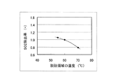
図4は、酸素燃焼運転中のボイラから排ガスを脱硫装置に導入したときに、吸収塔内における脱硫領域の温度と排ガス中のSO2除去率との関係を示す図である。ここで、脱硫領域とは、噴霧された吸収液と排ガスとが接触する領域を意味する。この図から、脱硫領域の温度が高くなるに従い、SO2除去率が低下することが分かる。これは、温度の上昇により、吸収液へのSO2の溶解度が低下するためと考えられる。 FIG. 4 is a diagram showing the relationship between the temperature of the desulfurization region in the absorption tower and the SO 2 removal rate in the exhaust gas when the exhaust gas is introduced into the desulfurizer from the boiler during the oxyfuel combustion operation. Here, a desulfurization area | region means the area | region where the sprayed absorption liquid and exhaust gas contact. From this figure, it can be seen that the SO 2 removal rate decreases as the temperature of the desulfurization region increases. This is presumably because the solubility of SO 2 in the absorbing solution decreases due to an increase in temperature.
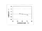
また、図5は、酸素燃焼運転中のボイラから排ガスを脱硫装置に導入したときに、吸収塔内における脱硫領域の温度と排ガス中の水銀除去率との関係を調査した結果を示す。この図から、脱硫領域の温度が高くなるに従い、水銀の除去率が低下することが分かる。これは、吸収塔で一度吸収液に吸収された酸化水銀が吸収液の液滴内で金属水銀に還元され、排ガス中に再放出される割合が増加したためと考えられる。 FIG. 5 shows the results of investigating the relationship between the temperature of the desulfurization region in the absorption tower and the mercury removal rate in the exhaust gas when the exhaust gas is introduced into the desulfurizer from the boiler during the oxyfuel combustion operation. From this figure, it can be seen that the mercury removal rate decreases as the temperature of the desulfurization region increases. This is thought to be because the mercury oxide once absorbed in the absorption liquid in the absorption tower was reduced to metallic mercury in the liquid droplets of the absorption liquid and re-released into the exhaust gas.
そこで、本発明の排ガス処理システムでは、上記課題を解決するため、富酸素ガスと循環排ガスとを混合した燃焼用ガスにより燃料を燃焼させるボイラと、このボイラから排出される排ガスが流れる煙道に配設された除塵装置と、この除塵装置の下流側の煙道を流れる排ガスを導入して脱硫処理する湿式脱硫装置と、除塵装置の下流側の煙道を分岐してこの煙道から抜き出した排ガスの一部をボイラに導く排ガス循環流路と、脱硫装置の下流側の煙道を流れる排ガスを圧縮して二酸化炭素を分離するCO2分離手段とを備えた排ガス処理システムにおいて、CO2分離手段の排ガスを圧縮する過程で分離された水分を、湿式脱硫装置内で循環して使用される吸収液に供給することを特徴としている。 Therefore, in the exhaust gas treatment system of the present invention, in order to solve the above problems, a boiler that burns fuel with a combustion gas in which oxygen-rich gas and circulating exhaust gas are mixed, and a flue through which the exhaust gas discharged from the boiler flows. The installed dust removal device, a wet desulfurization device that introduces desulfurization treatment by introducing exhaust gas flowing through the flue downstream of the dust removal device, and a flue downstream from the dust removal device are branched and extracted from the flue. In an exhaust gas treatment system comprising an exhaust gas circulation passage for leading a part of exhaust gas to a boiler, and a CO 2 separation means for compressing exhaust gas flowing through a flue downstream of a desulfurization apparatus and separating carbon dioxide, CO 2 separation The water separated in the process of compressing the exhaust gas of the means is supplied to the absorbent used by being circulated in the wet desulfurization apparatus.
すなわち、酸素燃焼方式のボイラから発生する排ガス中には、空気燃焼方式のボイラから発生する排ガスよりも多くの水分が含まれているため、CO2分離手段ではより多くの水分が回収される。ここで、CO2分離手段において回収される水分は、排ガス中の水蒸気が凝縮することで生じるドレン水であり、このドレン水の温度は分離手段に導入された排ガスの温度よりも低く、例えば常温で回収される。したがって、このようなドレン水を湿式脱硫装置内の吸収液に供給することで、吸収液の温度を下げ、脱硫装置内の温度、つまり脱硫領域の温度を低く保つことができる。これにより、脱硫装置を大型化することなく、脱硫性能及び水銀除去率の低下を抑制することができる。また、このようにCO2分離手段で回収されたドレン水を脱硫装置内の吸収液に供給することで、ドレン水に残存して溶け込んでいるSO2を脱硫装置内で分離することができる。これにより、脱硫性能の低下が抑制され、しかも、ドレン水の排水処理設備が不要となるため、システムの簡単化を図ることができ、設備費用を低減することができる。 That is, since the exhaust gas generated from the oxyfuel combustion boiler contains more moisture than the exhaust gas generated from the air combustion boiler, more water is recovered by the CO 2 separation means. Here, the moisture recovered in the CO 2 separation means is drain water generated by condensation of water vapor in the exhaust gas, and the temperature of this drain water is lower than the temperature of the exhaust gas introduced into the separation means, It is collected at. Therefore, by supplying such drain water to the absorption liquid in the wet desulfurization apparatus, the temperature of the absorption liquid can be lowered and the temperature in the desulfurization apparatus, that is, the temperature of the desulfurization region can be kept low. Thereby, the fall of desulfurization performance and a mercury removal rate can be suppressed, without enlarging a desulfurization apparatus. Further, by supplying the drain water collected by the CO 2 separation means to the absorbing liquid in the desulfurization apparatus, SO 2 remaining and dissolved in the drain water can be separated in the desulfurization apparatus. Thereby, since the fall of desulfurization performance is suppressed and the drainage waste water treatment equipment becomes unnecessary, simplification of a system can be achieved and equipment cost can be reduced.
より具体的には、湿式脱硫装置は、吸収塔内を上昇する排ガスに向けて吸収液を噴霧するスプレーノズルと、このスプレーノズルから噴霧された吸収液を回収して貯留する吸収塔底部と、この吸収塔底部に貯留された吸収液をスプレーノズルに供給する循環ポンプとを備え、CO2分離手段で分離された水分が吸収塔底部に供給されるように構成されてなるものとする。 More specifically, the wet desulfurization apparatus includes a spray nozzle that sprays the absorbing liquid toward the exhaust gas rising in the absorption tower, an absorption tower bottom that collects and stores the absorbing liquid sprayed from the spray nozzle, A circulation pump for supplying the absorption liquid stored in the bottom of the absorption tower to the spray nozzle is provided, and the water separated by the CO 2 separation means is supplied to the bottom of the absorption tower.
また、CO2分離手段で分離された水分を吸収塔底部に供給することに代えて、該水分をスプレーノズルの上方に配置された他のスプレーノズルに供給し、他のスプレーノズルから水分が噴霧されるように構成してもよい。 Further, instead of supplying the water separated by the CO 2 separation means to the bottom of the absorption tower, the water is supplied to another spray nozzle disposed above the spray nozzle, and the water is sprayed from the other spray nozzle. You may comprise.
すなわち、吸収液からの水銀の再放出は、吸収液中の水銀が液滴として吸収塔内を飛行する過程で発生する。このため、水銀を含まず、分離手段で分離された水分を上方のスプレーノズルから排ガスに向けて噴き込むことにより、吸収液の液滴から水銀が再放出するのを抑制することができ、水銀の除去率の低下を抑制することができる。 That is, the re-release of mercury from the absorption liquid occurs in the process of mercury in the absorption liquid flying as a droplet in the absorption tower. For this reason, mercury can be prevented from being re-released from the droplets of the absorbing liquid by injecting moisture separated by the separation means into the exhaust gas from the upper spray nozzle toward the exhaust gas. It is possible to suppress a decrease in the removal rate.
本発明の排ガス処理システムによれば、酸素燃焼運転時において、排ガス中の水分量が高い場合でも、簡単な構成で、かつ設備費用を抑えつつ、脱硫装置の脱硫性能及び水銀の除去特性の低下を抑制することができる。 According to the exhaust gas treatment system of the present invention, even when the amount of moisture in the exhaust gas is high at the time of oxyfuel operation, the desulfurization performance and mercury removal characteristics of the desulfurization apparatus are reduced with a simple configuration and reduced equipment costs. Can be suppressed.
以下、本発明を適用してなる排ガス処理システムの実施形態について、図1乃至図3を参照して説明する。なお、本実施形態の排ガス処理システムでは、ボイラで燃焼させる化石燃料として微粉炭を用いる例を説明するが、この例に限定されるものではない。 Hereinafter, an embodiment of an exhaust gas treatment system to which the present invention is applied will be described with reference to FIGS. 1 to 3. In addition, although the example which uses pulverized coal as a fossil fuel burned with a boiler is demonstrated in the exhaust gas treatment system of this embodiment, it is not limited to this example.
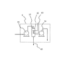
本実施形態の排ガス処理システムは、ボイラ1と、熱交換器3と、集塵機5と、脱硫装置7と、CO2分離手段9を備えて構成される。ボイラ1には、図示しないバーナが設けられており、このバーナには、微粉炭燃料を供給するための燃料供給経路11が接続されている。ボイラ1の出口には、排ガスが通流する第1の煙道13が接続されており、第1の煙道13の途中には、上流側から、熱交換器3、集塵機5、脱硫装置7、CO2分離手段9が順に配設されている。
The exhaust gas treatment system of the present embodiment includes a boiler 1, a
集塵機5と脱硫装置7を接続する第1の煙道13には、分配器15が設けられている。この分配器15には、第1の煙道13を流れる排ガスの一部を抜き出す排ガス再循環ダクト17の一端が接続されている。排ガス再循環ダクト17は、熱交換器3を経由して、バーナと連通する燃料供給経路11に設けられた排ガス混合器19に他端が接続されている。排ガス再循環ダクト17の分配器15と熱交換器3との間には、排ガス再循環ダクト17を流れる循環排ガスの流量を調節するための循環用ファン21が設けられており、例えば、ファン回転数を調節して循環排ガスの循環量を排ガス量全体の7〜8割とすることで、空気燃焼運転時と同等のガス温度に調節することが可能になっている。なお、排ガス再循環ダクト17は脱硫装置7の後流側の第1の煙道13を分岐させて接続するようにしてもよい。
A
燃料供給経路11には、図示しない石炭粉砕ミル等によって所定の粒度に粉砕された微粉炭が搬送用ガスに同伴されて供給されるようになっている。燃料供給経路11の排ガス混合器19の上流側には、酸素の供給経路が接続される酸素混合器23が設けられており、酸素混合器23には、空気から分離された高濃度の酸素が供給されて微粉炭燃料と酸素が混合されるようになっている。排ガス混合器19には、排ガス再循環ダクト17を流れる循環排ガスが供給され、ここで微粉炭燃料と酸素及び循環排ガスが混合されるようになっている。
The
熱交換器3は、ボイラ1から排出された排ガスと排ガス再循環ダクト17を通流する循環排ガスとを熱交換するようになっている。これにより、排ガス再循環ダクト17を通流する循環排ガスは、ボイラ1から排出された排ガスと熱交換して所定温度まで加熱される。
The
脱硫装置7は、図2に示すように、吸収塔25の下方に排ガスの導入口が設けられ、この導入口に第1の煙道13aが接続される一方、吸収塔25の頂部に排ガスの排出口が設けられ、この排出口に第1の煙道13bが接続されている。導入口と排出口の間の高さ領域には、吸収塔25内を上昇する排ガスに対して上から吸収液を噴き付けるスプレーノズル27が複数段で配設されている。導入口よりも低い位置には、スプレーノズル27から噴霧された吸収液を回収して貯留する底部29が形成されている。底部29に貯留された吸収液31は、循環ポンプ33によって汲み上げられて各スプレーノズル27に供給されるようになっている。
As shown in FIG. 2, the
CO2分離手段9は、第1の圧縮機35と、熱交換器37と、第2の圧縮機39が順に配管で接続され、排ガスを圧縮する過程で水分と二酸化炭素が順次分離されるようになっている。熱交換器37は、排ガスが導入される容器41内に冷却水が通流する伝熱管43を配設して構成される。熱交換器37の容器41には、排ガスから分離された水分を容器41内から抜き出す排水供給用ダクト45の一端が接続され、その他端は、脱硫装置7の底部29に接続されている。また、排水供給用ダクト45には、循環ポンプ47が設けられている。
The CO 2 separation means 9 is configured such that the
次に、このようにして構成される排ガス処理システムの動作を説明する。 Next, the operation of the exhaust gas treatment system configured as described above will be described.
ボイラ1には、微粉炭と酸素と循環排ガスが供給されて微粉炭が燃焼され、この燃焼熱により、図示しない蒸気発生器から高温高圧の蒸気が発生する。この蒸気は、図示しない蒸気タービン発電設備等に供給されて発電される。 The boiler 1 is supplied with pulverized coal, oxygen and circulating exhaust gas, and the pulverized coal is combusted, and high-temperature and high-pressure steam is generated from a steam generator (not shown) by this combustion heat. This steam is supplied to a steam turbine power generation facility (not shown) to generate power.
一方、ボイラ1から排出された排ガスは、第1の煙道13を通り、熱交換器3に導かれて減温(例えば、約160℃〜200℃)される。熱交換器3を出た排ガスは、集塵機5に導かれて排ガスに含まれる煤塵成分が除去される。
On the other hand, the exhaust gas discharged from the boiler 1 passes through the
集塵機5を出た排ガスは、脱硫装置7の吸収塔25に導入され、吸収塔25内を上昇する際にスプレーノズル27から噴霧された吸収液と接触する。これにより、排ガスに含まれるSO2と水銀は、吸収液に吸収された状態で吸収塔25の底部29に貯留される。ここで、吸収液に吸収されたSO2は、H2SO3となり、さらに吸収液中のCaCO3と反応してCaSO3となる。そして、底部29に溜められた吸収液31中に酸化用空気が供給されることで、CaSO3が酸化されてCaSO4となり、吸収液31から分離される。一方、吸収液に吸収された水銀は、吸収液中で酸化水銀となり、底部29に溜められた吸収液31から分離される。これにより、CaSO4と酸化水銀が分離された底部29の吸収液31は、循環ポンプ33で汲み上げられてスプレーノズル27に供給され、再び吸収塔25内に噴霧される。
The exhaust gas exiting the dust collector 5 is introduced into the
続いて、脱硫装置7を出た排ガスは、CO2分離手段9に導かれる。この分離装置9では、まず、排ガスが第1の圧縮機35で圧縮(例えば、約1.5MPaで加圧)され、その圧縮により発生した熱が、熱交換器37の伝熱管43で除熱される。この除熱により、排ガスが常温程度まで冷却されるとともに排ガスに含まれる水分の殆どが凝縮して液化され、ドレン水となって分離される。水分が分離された排ガスは、さらに第2の圧縮機39で圧縮されることで液化した二酸化炭素が分離される。分離された液状の二酸化炭素は、図示しない二酸化炭素貯蔵器に貯蔵される。なお、CO2分離手段9を出た排ガスは、図示しない煙突から大気中へ放出される。
Subsequently, the exhaust gas exiting the
ところで、吸収塔25に導入された排ガスは、その熱で吸収液の水分が蒸発するときに熱が奪われるため、所定の温度に減温される。一方、吸収塔25内には熱を外に逃がす手段がないことから、吸収塔25に導入される排ガスの水分濃度によって、吸収塔25内の排ガス温度が変化する。例えば、通常の空気燃焼運転時では、ボイラから排出される排ガスの水分濃度が約10%と低いため、吸収塔25内で、約55℃まで減温される。これに対し、酸素燃焼運転時では、ボイラから排出される排ガスは、窒素を含まず水分濃度が30〜35%と高いため、吸収塔25内で、約70℃までしか減温されない。このように、吸収塔25内の排ガス温度が上昇すると、スプレーノズル27から噴霧された吸収液と排ガスが接触する脱硫領域の温度、及び、吸収液の温度が上昇し、その結果、脱硫装置7の脱硫性能及び水銀の除去特性が低下するおそれがある(図4、5)。
By the way, the exhaust gas introduced into the
これに対し、本実施形態では、CO2分離手段9で分離されたドレン水を循環ポンプ47によって熱交換器37から抜き出し、排水供給用ダクト45を介して吸収塔25の底部29に供給するようにしている。ここで、ドレン水はおよそ20℃の状態で回収されるため、この20℃のドレン水を吸収塔25の底部29に貯留される吸収液31に供給することで、吸収塔25内を循環する吸収液の温度を下げることができる。そして、吸収液の温度が下がることで、吸収塔25内を流れる排ガスが減温されるため、脱硫領域の温度を例えば50℃まで下げることが可能となる。よって、本実施形態によれば、酸素燃焼運転時のボイラから発生する排ガスのように、排ガス中の水分濃度が高い場合でも、脱硫装置7の脱硫性能や水銀除去性能を空気燃焼運転時と同等程度に維持することができる。なお、吸収塔25内にドレン水が供給されることで吸収液の濃度が次第に減少するが、この点については、例えば、吸収液の濃度を所定の範囲に保持するように吸収液中に薬剤を定期的に添加することで、濃度を一定に保つことができる。
On the other hand, in this embodiment, the drain water separated by the CO 2 separation means 9 is extracted from the
また、本実施形態では、CO2分離手段9で分離されたドレン水を吸収塔25に供給することにより、ドレン水に溶け込んでいるSO2等を吸収塔25内で分離することができる。これにより、凝縮水の排水処理設備が不要となるため、システムの簡単化を図ることができ、設備費用の低減が可能となる。
In the present embodiment, the drain water separated by the CO 2 separation means 9 is supplied to the
また、本実施形態では、既設の排ガス処理システムにおいて、CO2分離手段9で分離されたドレン水を吸収塔25の底部29に供給する排水供給用ダクト45を増設するだけでよいため、設備の増設費用を少なく抑えることができる。
Moreover, in this embodiment, since it is only necessary to add the
また、本実施形態では、CO2分離手段9で分離されたドレン水を吸収塔25の底部29に供給しているが、ドレン水の供給先は、この例に限られるものではなく、例えば、図6に示すように、吸収塔25内のスプレーノズル27の上方に設置されたドレン水専用のスプレーノズル49に供給するようにしてもよい。
In the present embodiment, the drain water separated by the CO 2 separation means 9 is supplied to the bottom 29 of the
図6の脱硫装置7は、導入口と排出口の間の高さ領域に、吸収塔25内を上昇する排ガスに対して上から吸収液を噴き付けるスプレーノズル27と、このスプレーノズル27の上方に配置され、排ガスに対して上からドレン水を噴き付けるスプレーノズル49が設けられている。スプレーノズル49にはドレン水のみが供給されるようになっている。スプレーノズル27、49は、それぞれ複数段で設けられていてもよいが、スプレーノズル49は常にスプレーノズル27の上方に配置されているものとする。
The
このように構成しても、吸収塔25内を流れる排ガスは、スプレーノズル49から噴き込まれたドレン水によって減温され、脱硫領域の温度が例えば50℃まで減温されるため、脱硫装置7における脱硫性能を空気燃焼運転時と同等以上とすることができる。また、水銀を含まないドレン水をスプレーノズル49から噴き込んでいるため、スプレーノズル27から噴き込まれた吸収液の液滴が浮遊する領域をドレン水の液滴で包囲することができる。これにより、水銀を含んだ吸収液の液滴から水銀が再放出するのを抑制できるため、水銀の除去率を空気燃焼運転時と同等以上とすることができる。
Even in this configuration, the temperature of the exhaust gas flowing in the
1 ボイラ
3 熱交換器
5 集塵機
7 脱硫装置
9 CO2分離手段
13 第1の煙道
17 排ガス再循環ダクト
21 循環用ファン
25 吸収塔
27、49 スプレーノズル
29 底部
31 吸収液
33、47 循環ポンプ
35 第1の圧縮機
37 熱交換器
39 第2の圧縮機
45 排水供給用ダクト
1
Claims (3)
前記CO2分離手段で分離された水分が前記吸収塔底部に供給されるように構成されてなる請求項1に記載の排ガス処理システム。 The wet desulfurization apparatus includes a spray nozzle for spraying an absorbing liquid toward exhaust gas rising in the absorption tower, an absorption tower bottom for collecting and storing the absorbing liquid sprayed from the spray nozzle, and the absorption tower bottom A circulation pump for supplying the absorption liquid stored in the spray nozzle to the spray nozzle,
The exhaust gas treatment system according to claim 1, wherein the water separated by the CO 2 separation means is configured to be supplied to the bottom of the absorption tower.
前記CO2分離手段で分離された水分が前記スプレーノズルの上方に配置された他のスプレーノズルから噴霧されるように構成されてなる請求項1に記載の排ガス処理システム。 The wet desulfurization apparatus includes a spray nozzle for spraying an absorbing liquid toward exhaust gas rising in the absorption tower, an absorption tower bottom for collecting and storing the absorbing liquid sprayed from the spray nozzle, and the absorption tower bottom A circulation pump for supplying the absorption liquid stored in the spray nozzle to the spray nozzle,
The exhaust gas treatment system according to claim 1, wherein the moisture separated by the CO 2 separation means is sprayed from another spray nozzle disposed above the spray nozzle.
Priority Applications (1)
| Application Number | Priority Date | Filing Date | Title |
|---|---|---|---|
| JP2011003360A JP2012143699A (en) | 2011-01-11 | 2011-01-11 | Exhaust gas treating system |
Applications Claiming Priority (1)
| Application Number | Priority Date | Filing Date | Title |
|---|---|---|---|
| JP2011003360A JP2012143699A (en) | 2011-01-11 | 2011-01-11 | Exhaust gas treating system |
Publications (1)
| Publication Number | Publication Date |
|---|---|
| JP2012143699A true JP2012143699A (en) | 2012-08-02 |
Family
ID=46787839
Family Applications (1)
| Application Number | Title | Priority Date | Filing Date |
|---|---|---|---|
| JP2011003360A Ceased JP2012143699A (en) | 2011-01-11 | 2011-01-11 | Exhaust gas treating system |
Country Status (1)
| Country | Link |
|---|---|
| JP (1) | JP2012143699A (en) |
Cited By (11)
| Publication number | Priority date | Publication date | Assignee | Title |
|---|---|---|---|---|
| WO2014057652A1 (en) * | 2012-10-09 | 2014-04-17 | 株式会社Ihi | Compressor impurity-removal system |
| WO2014064894A1 (en) * | 2012-10-24 | 2014-05-01 | 株式会社Ihi | System for removal of impurities by compressor |
| CN103861426A (en) * | 2012-12-11 | 2014-06-18 | 中国石油化工集团公司 | Method for desulphurization and dust removal of flue gas and recycling of sodium sulfite |
| JP2014213298A (en) * | 2013-04-30 | 2014-11-17 | 株式会社Ihi | Method and apparatus of supplying alkaline modifier in compressor impurity separation mechanism |
| JP2014213297A (en) * | 2013-04-30 | 2014-11-17 | 株式会社Ihi | Method and apparatus of preventing corrosion in compressor impurity separation mechanism |
| WO2015005296A1 (en) * | 2013-07-12 | 2015-01-15 | 株式会社Ihi | Exhaust gas purification device and co2 recovery system |
| KR101485689B1 (en) * | 2013-07-29 | 2015-01-28 | 주식회사 포스코 | Apparatus for removing vapor of dust collector |
| WO2015041102A1 (en) * | 2013-09-17 | 2015-03-26 | 株式会社Ihi | Exhaust gas processing system and processing method |
| US10376835B2 (en) | 2013-06-10 | 2019-08-13 | Ihi Corporation | Device for removing impurities from water-containing gas and impurities removal system |
| CN111514735A (en) * | 2020-05-29 | 2020-08-11 | 广东佳德环保科技有限公司 | System and method for desulfurization and denitrification by using ozone |
| US20210220772A1 (en) * | 2019-10-29 | 2021-07-22 | Huaneng Clean Energy Research Institute | Flue gas low-temperature adsorption denitrification method |
Citations (5)
| Publication number | Priority date | Publication date | Assignee | Title |
|---|---|---|---|---|
| JPH05126324A (en) * | 1991-10-31 | 1993-05-21 | Chiyoda Corp | Method of incinerating city refuse |
| JP2005087828A (en) * | 2003-09-16 | 2005-04-07 | Kansai Electric Power Co Inc:The | Desulfurization decarbonation method and its apparatus |
| JP2006527153A (en) * | 2003-06-12 | 2006-11-30 | カンソルブ・テクノロジーズ・インコーポレーテツド | Method for recovering CO2 from a gas stream |
| JP2010107129A (en) * | 2008-10-31 | 2010-05-13 | Hitachi Ltd | Oxygen burning boiler system and method of controlling the same |
| JP2010235395A (en) * | 2009-03-31 | 2010-10-21 | Hitachi Ltd | Apparatus for recovering carbon dioxide, and thermal power system with apparatus for recovering carbon dioxide |
-
2011
- 2011-01-11 JP JP2011003360A patent/JP2012143699A/en not_active Ceased
Patent Citations (5)
| Publication number | Priority date | Publication date | Assignee | Title |
|---|---|---|---|---|
| JPH05126324A (en) * | 1991-10-31 | 1993-05-21 | Chiyoda Corp | Method of incinerating city refuse |
| JP2006527153A (en) * | 2003-06-12 | 2006-11-30 | カンソルブ・テクノロジーズ・インコーポレーテツド | Method for recovering CO2 from a gas stream |
| JP2005087828A (en) * | 2003-09-16 | 2005-04-07 | Kansai Electric Power Co Inc:The | Desulfurization decarbonation method and its apparatus |
| JP2010107129A (en) * | 2008-10-31 | 2010-05-13 | Hitachi Ltd | Oxygen burning boiler system and method of controlling the same |
| JP2010235395A (en) * | 2009-03-31 | 2010-10-21 | Hitachi Ltd | Apparatus for recovering carbon dioxide, and thermal power system with apparatus for recovering carbon dioxide |
Cited By (26)
| Publication number | Priority date | Publication date | Assignee | Title |
|---|---|---|---|---|
| JP2014076405A (en) * | 2012-10-09 | 2014-05-01 | Ihi Corp | Compressor impurities removal system |
| WO2014057652A1 (en) * | 2012-10-09 | 2014-04-17 | 株式会社Ihi | Compressor impurity-removal system |
| AU2013328171B2 (en) * | 2012-10-09 | 2016-04-21 | Ihi Corporation | Compressor impurity-removal system |
| US9149766B2 (en) | 2012-10-09 | 2015-10-06 | Ihi Corporation | Compressor impurity-removal system |
| CN104684628A (en) * | 2012-10-09 | 2015-06-03 | 株式会社Ihi | Compressor impurity-removal system |
| US9149765B2 (en) | 2012-10-24 | 2015-10-06 | Ihi Corporation | System for removal of impurities by compressor |
| WO2014064894A1 (en) * | 2012-10-24 | 2014-05-01 | 株式会社Ihi | System for removal of impurities by compressor |
| JP2014083494A (en) * | 2012-10-24 | 2014-05-12 | Ihi Corp | Compressor impurity removing system |
| CN104755153B (en) * | 2012-10-24 | 2016-08-24 | 株式会社Ihi | Compressor impurity removes system |
| AU2013336144B2 (en) * | 2012-10-24 | 2016-04-21 | Ihi Corporation | System for removal of impurities by compressor |
| CN104755153A (en) * | 2012-10-24 | 2015-07-01 | 株式会社Ihi | System for removal of impurities by compressor |
| CN103861426A (en) * | 2012-12-11 | 2014-06-18 | 中国石油化工集团公司 | Method for desulphurization and dust removal of flue gas and recycling of sodium sulfite |
| JP2014213297A (en) * | 2013-04-30 | 2014-11-17 | 株式会社Ihi | Method and apparatus of preventing corrosion in compressor impurity separation mechanism |
| JP2014213298A (en) * | 2013-04-30 | 2014-11-17 | 株式会社Ihi | Method and apparatus of supplying alkaline modifier in compressor impurity separation mechanism |
| US9945609B2 (en) | 2013-04-30 | 2018-04-17 | Ihi Corporation | Alkalinity control agent supply method and apparatus for compressor impurity separation mechanism |
| US9669353B2 (en) | 2013-04-30 | 2017-06-06 | Ihi Corporation | Method and apparatus for preventing corrosion of compressor impurity separation mechanism |
| US10376835B2 (en) | 2013-06-10 | 2019-08-13 | Ihi Corporation | Device for removing impurities from water-containing gas and impurities removal system |
| WO2015005296A1 (en) * | 2013-07-12 | 2015-01-15 | 株式会社Ihi | Exhaust gas purification device and co2 recovery system |
| US10737217B2 (en) | 2013-07-12 | 2020-08-11 | Ihi Corporation | Exhaust gas purification device and CO2 recovery system |
| KR101485689B1 (en) * | 2013-07-29 | 2015-01-28 | 주식회사 포스코 | Apparatus for removing vapor of dust collector |
| WO2015041102A1 (en) * | 2013-09-17 | 2015-03-26 | 株式会社Ihi | Exhaust gas processing system and processing method |
| US10532312B2 (en) | 2013-09-17 | 2020-01-14 | Ihi Corporation | Exhaust gas processing system and processing method |
| US20210220772A1 (en) * | 2019-10-29 | 2021-07-22 | Huaneng Clean Energy Research Institute | Flue gas low-temperature adsorption denitrification method |
| US11925898B2 (en) * | 2019-10-29 | 2024-03-12 | Huaneng Clean Energy Research Institute | Flue gas low-temperature adsorption denitrification method |
| CN111514735A (en) * | 2020-05-29 | 2020-08-11 | 广东佳德环保科技有限公司 | System and method for desulfurization and denitrification by using ozone |
| CN111514735B (en) * | 2020-05-29 | 2024-03-08 | 广东佳德环保科技有限公司 | System and method for desulfurization and denitrification by utilizing ozone |
Similar Documents
| Publication | Publication Date | Title |
|---|---|---|
| JP2012143699A (en) | Exhaust gas treating system | |
| JP5489254B2 (en) | Oxyfuel combustion system and operating method thereof | |
| RU2315186C2 (en) | Low contamination thermal power station | |
| JP4644725B2 (en) | Oxy-combustion boiler system, pulverized-coal-fired boiler remodeling method, oxy-combustion boiler system control device | |
| US7559977B2 (en) | Purification works for thermal power plant | |
| KR101401813B1 (en) | Method and device for separating carbon dioxide from an exhaust gas of a fossil fired power plant | |
| US8834609B2 (en) | Method and device for separating carbon dioxide from a waste gas of a fossil fuel-operated power plant | |
| US20090101012A1 (en) | Multi-stage co2 removal system and method for processing a flue gas stream | |
| WO2010113364A1 (en) | Apparatus for recovering co2 and method therefor | |
| JP5717382B2 (en) | Smoke exhaust treatment device and smoke exhaust treatment method | |
| JP5448858B2 (en) | Oxy-combustion power plant and its operation method | |
| KR20080041580A (en) | Power plants that utilize gas turbines for power generation and processes for lowering co2 emissions | |
| JP2010235395A (en) | Apparatus for recovering carbon dioxide, and thermal power system with apparatus for recovering carbon dioxide | |
| JP2010172878A (en) | Exhaust gas treatment device of coal-fired boiler of oxygen combustion type and method using this device | |
| JP5721605B2 (en) | Power plant | |
| JP2012063041A (en) | Oxy-combustion boiler | |
| JP4929227B2 (en) | Gas turbine system using high humidity air | |
| JP2012137269A (en) | Coal fired power generation plant and method of controlling the same | |
| JP5039719B2 (en) | High humidity gas turbine system and recovered water degassing method for gas turbine system | |
| JP2012149792A (en) | Exhausts gas treatment system | |
| JP2014059104A (en) | Oxyfuel combustion boiler system | |
| KR101592765B1 (en) | Combined cycle power generation system | |
| JP2002138852A (en) | Gas turbine facilities | |
| KR101704877B1 (en) | Integrated gasification combined cycle system | |
| JP2013057437A (en) | Oxygen combustion system and oxygen combustion method |
Legal Events
| Date | Code | Title | Description |
|---|---|---|---|
| A621 | Written request for application examination |
Free format text: JAPANESE INTERMEDIATE CODE: A621 Effective date: 20140110 |
|
| A977 | Report on retrieval |
Free format text: JAPANESE INTERMEDIATE CODE: A971007 Effective date: 20140926 |
|
| A131 | Notification of reasons for refusal |
Free format text: JAPANESE INTERMEDIATE CODE: A131 Effective date: 20140930 |
|
| A521 | Written amendment |
Free format text: JAPANESE INTERMEDIATE CODE: A523 Effective date: 20141126 |
|
| A711 | Notification of change in applicant |
Free format text: JAPANESE INTERMEDIATE CODE: A712 Effective date: 20141224 |
|
| A01 | Written decision to grant a patent or to grant a registration (utility model) |
Free format text: JAPANESE INTERMEDIATE CODE: A01 Effective date: 20150526 |
|
| A045 | Written measure of dismissal of application |
Free format text: JAPANESE INTERMEDIATE CODE: A045 Effective date: 20150929 |