JP2012141015A - 防振パッド - Google Patents
防振パッド Download PDFInfo
- Publication number
- JP2012141015A JP2012141015A JP2010294361A JP2010294361A JP2012141015A JP 2012141015 A JP2012141015 A JP 2012141015A JP 2010294361 A JP2010294361 A JP 2010294361A JP 2010294361 A JP2010294361 A JP 2010294361A JP 2012141015 A JP2012141015 A JP 2012141015A
- Authority
- JP
- Japan
- Prior art keywords
- reinforcing member
- vibration
- cylindrical reinforcing
- elastic sheet
- pad
- Prior art date
- Legal status (The legal status is an assumption and is not a legal conclusion. Google has not performed a legal analysis and makes no representation as to the accuracy of the status listed.)
- Granted
Links
- 230000003014 reinforcing effect Effects 0.000 claims abstract description 119
- 239000000463 material Substances 0.000 claims abstract description 31
- 239000013013 elastic material Substances 0.000 claims abstract description 12
- 230000002093 peripheral effect Effects 0.000 claims abstract description 5
- 125000006850 spacer group Chemical group 0.000 claims description 3
- 230000007306 turnover Effects 0.000 abstract 1
- 238000002955 isolation Methods 0.000 description 25
- 230000004048 modification Effects 0.000 description 25
- 238000012986 modification Methods 0.000 description 25
- 238000010586 diagram Methods 0.000 description 18
- 229920003002 synthetic resin Polymers 0.000 description 15
- 239000000057 synthetic resin Substances 0.000 description 15
- 239000000499 gel Substances 0.000 description 14
- 229920001296 polysiloxane Polymers 0.000 description 12
- 239000002184 metal Substances 0.000 description 10
- 229910052751 metal Inorganic materials 0.000 description 10
- 230000000694 effects Effects 0.000 description 9
- 229920005989 resin Polymers 0.000 description 7
- 239000011347 resin Substances 0.000 description 7
- 238000004519 manufacturing process Methods 0.000 description 6
- 230000002787 reinforcement Effects 0.000 description 5
- 239000000853 adhesive Substances 0.000 description 4
- 230000001070 adhesive effect Effects 0.000 description 4
- 229920005549 butyl rubber Polymers 0.000 description 4
- 229920001971 elastomer Polymers 0.000 description 3
- 239000004033 plastic Substances 0.000 description 3
- 230000002265 prevention Effects 0.000 description 3
- 229910001369 Brass Inorganic materials 0.000 description 2
- 238000010521 absorption reaction Methods 0.000 description 2
- 239000010951 brass Substances 0.000 description 2
- 238000002347 injection Methods 0.000 description 2
- 239000007924 injection Substances 0.000 description 2
- 238000009434 installation Methods 0.000 description 2
- 238000000034 method Methods 0.000 description 2
- 239000007779 soft material Substances 0.000 description 2
- 239000010935 stainless steel Substances 0.000 description 2
- 229910001220 stainless steel Inorganic materials 0.000 description 2
- 229910000881 Cu alloy Inorganic materials 0.000 description 1
- 229910000831 Steel Inorganic materials 0.000 description 1
- 229910052782 aluminium Inorganic materials 0.000 description 1
- XAGFODPZIPBFFR-UHFFFAOYSA-N aluminium Chemical compound [Al] XAGFODPZIPBFFR-UHFFFAOYSA-N 0.000 description 1
- 230000008602 contraction Effects 0.000 description 1
- 230000000994 depressogenic effect Effects 0.000 description 1
- 238000004512 die casting Methods 0.000 description 1
- 238000010030 laminating Methods 0.000 description 1
- 239000002245 particle Substances 0.000 description 1
- 230000000149 penetrating effect Effects 0.000 description 1
- 229920000642 polymer Polymers 0.000 description 1
- 238000003825 pressing Methods 0.000 description 1
- 238000010079 rubber tapping Methods 0.000 description 1
- 239000010959 steel Substances 0.000 description 1
- 229920005992 thermoplastic resin Polymers 0.000 description 1
Images

Landscapes
- Buildings Adapted To Withstand Abnormal External Influences (AREA)
- Vibration Prevention Devices (AREA)
Abstract
【解決手段】本実施形態に係る防振パッド10は、重量物の転倒を防止するために前記重量物の下に敷かれる防振パッド10において、弾性材料からなる弾性シート11と、弾性シート11を補強するために弾性シート11と一体に設置される共に、周壁により内部を囲う筒部17a,17bを有して硬質材料から形成された筒状補強部材15と、を備え、筒状補強部材15の内部に、弾性シート11が存在しない中空部13が形成されていることを特徴とする。
【選択図】図1
Description
(第一実施形態)
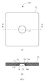
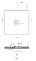
まず、図1を参照しながら、第一実施形態に係る防振パッドについて説明する。図1は、第一実施形態に係る防振パッドの構成を示す図であり、図1(a)が、防振パッドの平面図、図1(b)が、図1(a)のA−A線による断面図である。
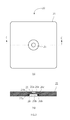
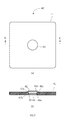
次に、図3を参照しながら、第二実施形態に係る防振パッドについて説明する。図3は、第二実施形態に係る防振パッドの構成を示す図であり、図3(a)が、防振パッドの平面図、図3(b)が、図3(a)のC−C線による断面図である。
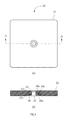
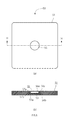
次に、図4を参照しながら、第三実施形態に係る防振パッドについて説明する。図4は、第三実施形態に係る防振パッドの構成を示す図であり、図4(a)が、防振パッドの平面図、図4(b)が、図4(a)のD−D線による断面図である。
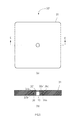
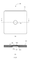
次に、図6を参照しながら、第四実施形態に係る防振パッドについて説明する。図6は、第四実施形態に係る防振パッドの構成を示す図であり、図6(a)が、防振パッドの平面図、図6(b)が、図6(a)のF−F線による断面図である。
次に、図8を参照しながら、第五実施形態に係る防振パッドについて説明する。図8は、第五実施形態に係る防振パッドの構成を示す図であり、図8(a)が、防振パッドの平面図、図8(b)が、図8(a)のH−H線による断面図である。
次に、図9を参照しながら、第六実施形態に係る防振パッドについて説明する。図9は、第六実施形態に係る防振パッドの構成を示す図であり、図9(a)が、防振パッドの平面図、図9(b)が、図9(a)のI−I線による断面図である。
11,21,31,41,51,61 弾性シート
13,23,33、43,53,63 中空部
15,25,35,45,55,65 筒状補強部材
16,26,36,46,56,66 面部
17,27,37,47,57,67 円筒部
19,29,39,49 リング
Claims (5)
- 重量物の転倒を防止するために前記重量物の下に敷かれる防振パッドにおいて、
弾性材料からなる弾性シートと、
前記弾性シートを補強するために前記弾性シートと一体に設置されると共に、周壁により内部を囲う筒部を有して硬質材料から形成された筒状補強部材と、を備え、
前記筒状補強部材の内部に、前記弾性シートが存在しない中空部が形成されていることを特徴とする防振パッド。 - 前記筒状補強部材は、前記重量物の荷重を受ける支持部が複数段形成されていることを特徴とする請求項1記載の防振パッド。
- 前記筒状補強部材の上部又は下部の少なくとも一方に開口が形成されていることを特徴とする請求項1又は2記載の防振パッド。
- 前記筒状補強部材の内部に設置された、当該筒状補強部材が完全につぶれてしまうのを防止するためのスペーサーをさらに備えることを特徴とする請求項1乃至3何れか1項に記載の防振パッド。
- 前記弾性シートは、前記筒状補強部材の内側と外側とで異なる材料から形成されていることを特徴とする請求項1乃至4の何れか1項に記載の防振パッド。
Priority Applications (1)
| Application Number | Priority Date | Filing Date | Title |
|---|---|---|---|
| JP2010294361A JP4730978B1 (ja) | 2010-12-29 | 2010-12-29 | 防振パッド |
Applications Claiming Priority (1)
| Application Number | Priority Date | Filing Date | Title |
|---|---|---|---|
| JP2010294361A JP4730978B1 (ja) | 2010-12-29 | 2010-12-29 | 防振パッド |
Related Child Applications (1)
| Application Number | Title | Priority Date | Filing Date |
|---|---|---|---|
| JP2011067513A Division JP2012141054A (ja) | 2011-03-25 | 2011-03-25 | 防振パッド |
Publications (2)
| Publication Number | Publication Date |
|---|---|
| JP4730978B1 JP4730978B1 (ja) | 2011-07-20 |
| JP2012141015A true JP2012141015A (ja) | 2012-07-26 |
Family
ID=44461711
Family Applications (1)
| Application Number | Title | Priority Date | Filing Date |
|---|---|---|---|
| JP2010294361A Active JP4730978B1 (ja) | 2010-12-29 | 2010-12-29 | 防振パッド |
Country Status (1)
| Country | Link |
|---|---|
| JP (1) | JP4730978B1 (ja) |
Cited By (2)
| Publication number | Priority date | Publication date | Assignee | Title |
|---|---|---|---|---|
| JP2012013220A (ja) * | 2010-08-26 | 2012-01-19 | Yasuteru Saeki | 防振パッド |
| JP2018071555A (ja) * | 2016-10-24 | 2018-05-10 | 株式会社安震 | 制震パッド |
Citations (8)
| Publication number | Priority date | Publication date | Assignee | Title |
|---|---|---|---|---|
| JPH03121815A (ja) * | 1989-10-04 | 1991-05-23 | K F C:Kk | モルタル等の混練圧送装置 |
| JPH03142382A (ja) * | 1989-10-30 | 1991-06-18 | Sharp Corp | 高周波デバイスの特性測定装置 |
| JPH0442939U (ja) * | 1990-08-09 | 1992-04-13 | ||
| JPH05257485A (ja) * | 1992-03-13 | 1993-10-08 | Railway Technical Res Inst | 磁性複合型制振材および磁性複合型制振材施工法 |
| JPH0690506A (ja) * | 1992-09-08 | 1994-03-29 | Toyota Motor Corp | 電気自動車用半導体制御素子の冷却装置 |
| JPH0835528A (ja) * | 1994-07-26 | 1996-02-06 | Mitsubishi Motors Corp | クラッチ構造 |
| JP2008255975A (ja) * | 2007-03-12 | 2008-10-23 | Uchiyama Mfg Corp | 制振ワッシャ |
| JP2009174666A (ja) * | 2008-01-25 | 2009-08-06 | Seiwa Electric Mfg Co Ltd | 通電機能付き防振部材およびそれを備えた機械装置 |
-
2010
- 2010-12-29 JP JP2010294361A patent/JP4730978B1/ja active Active
Patent Citations (8)
| Publication number | Priority date | Publication date | Assignee | Title |
|---|---|---|---|---|
| JPH03121815A (ja) * | 1989-10-04 | 1991-05-23 | K F C:Kk | モルタル等の混練圧送装置 |
| JPH03142382A (ja) * | 1989-10-30 | 1991-06-18 | Sharp Corp | 高周波デバイスの特性測定装置 |
| JPH0442939U (ja) * | 1990-08-09 | 1992-04-13 | ||
| JPH05257485A (ja) * | 1992-03-13 | 1993-10-08 | Railway Technical Res Inst | 磁性複合型制振材および磁性複合型制振材施工法 |
| JPH0690506A (ja) * | 1992-09-08 | 1994-03-29 | Toyota Motor Corp | 電気自動車用半導体制御素子の冷却装置 |
| JPH0835528A (ja) * | 1994-07-26 | 1996-02-06 | Mitsubishi Motors Corp | クラッチ構造 |
| JP2008255975A (ja) * | 2007-03-12 | 2008-10-23 | Uchiyama Mfg Corp | 制振ワッシャ |
| JP2009174666A (ja) * | 2008-01-25 | 2009-08-06 | Seiwa Electric Mfg Co Ltd | 通電機能付き防振部材およびそれを備えた機械装置 |
Cited By (2)
| Publication number | Priority date | Publication date | Assignee | Title |
|---|---|---|---|---|
| JP2012013220A (ja) * | 2010-08-26 | 2012-01-19 | Yasuteru Saeki | 防振パッド |
| JP2018071555A (ja) * | 2016-10-24 | 2018-05-10 | 株式会社安震 | 制震パッド |
Also Published As
| Publication number | Publication date |
|---|---|
| JP4730978B1 (ja) | 2011-07-20 |
Similar Documents
| Publication | Publication Date | Title |
|---|---|---|
| CN105518335B (zh) | 弹簧座 | |
| JP5542581B2 (ja) | 防振パッド | |
| JP4730978B1 (ja) | 防振パッド | |
| CN102705412A (zh) | 一种衬套式悬置 | |
| JP5244244B2 (ja) | 防振装置 | |
| JP2012141054A (ja) | 防振パッド | |
| JP4606516B1 (ja) | 防振パッド | |
| JP2003118818A (ja) | 制振ラックとラックの制振方法 | |
| JP2009008181A (ja) | プラグ入り免震装置の製造方法 | |
| JP2012246643A (ja) | 免震装置 | |
| JP3737439B2 (ja) | 防振支持具 | |
| CN206608503U (zh) | 一种钢构阻尼隔震减震器 | |
| JP6978086B2 (ja) | 圧縮機および圧縮機用支持部材 | |
| KR100704250B1 (ko) | 이중 바닥재의 지지대 및 그의 제조 방법과 그 지지대의사용 방법 | |
| JP2018132175A (ja) | アッパサポート | |
| CN207349335U (zh) | 一种车身悬置 | |
| JP3142382U (ja) | 転倒防止用器材および転倒防止された構築物 | |
| JP2012202107A (ja) | 建物床用の防振装置及び建物の床構造 | |
| CN103225663A (zh) | 振动控制设备 | |
| JP5330486B2 (ja) | 支承装置 | |
| JP2006308063A (ja) | 免震支承 | |
| JP4850875B2 (ja) | パレット | |
| JP4511420B2 (ja) | ダイナミックダンパ | |
| JP6051325B1 (ja) | 同心円積層型減衰材を備えた免震装置 | |
| JP7382867B2 (ja) | 建物本体の支持構造 |
Legal Events
| Date | Code | Title | Description |
|---|---|---|---|
| A131 | Notification of reasons for refusal |
Free format text: JAPANESE INTERMEDIATE CODE: A131 Effective date: 20110307 |
|
| A975 | Report on accelerated examination |
Free format text: JAPANESE INTERMEDIATE CODE: A971005 Effective date: 20110303 |
|
| A521 | Request for written amendment filed |
Free format text: JAPANESE INTERMEDIATE CODE: A523 Effective date: 20110325 |
|
| TRDD | Decision of grant or rejection written | ||
| A01 | Written decision to grant a patent or to grant a registration (utility model) |
Free format text: JAPANESE INTERMEDIATE CODE: A01 Effective date: 20110414 |
|
| A01 | Written decision to grant a patent or to grant a registration (utility model) |
Free format text: JAPANESE INTERMEDIATE CODE: A01 |
|
| A61 | First payment of annual fees (during grant procedure) |
Free format text: JAPANESE INTERMEDIATE CODE: A61 Effective date: 20110418 |
|
| FPAY | Renewal fee payment (event date is renewal date of database) |
Free format text: PAYMENT UNTIL: 20170428 Year of fee payment: 6 |
|
| R150 | Certificate of patent or registration of utility model |
Ref document number: 4730978 Country of ref document: JP Free format text: JAPANESE INTERMEDIATE CODE: R150 Free format text: JAPANESE INTERMEDIATE CODE: R150 |
|
| R250 | Receipt of annual fees |
Free format text: JAPANESE INTERMEDIATE CODE: R250 |
|
| R250 | Receipt of annual fees |
Free format text: JAPANESE INTERMEDIATE CODE: R250 |
|
| R250 | Receipt of annual fees |
Free format text: JAPANESE INTERMEDIATE CODE: R250 |