JP2012141015A - Vibration absorbing pad - Google Patents
Vibration absorbing pad Download PDFInfo
- Publication number
- JP2012141015A JP2012141015A JP2010294361A JP2010294361A JP2012141015A JP 2012141015 A JP2012141015 A JP 2012141015A JP 2010294361 A JP2010294361 A JP 2010294361A JP 2010294361 A JP2010294361 A JP 2010294361A JP 2012141015 A JP2012141015 A JP 2012141015A
- Authority
- JP
- Japan
- Prior art keywords
- reinforcing member
- vibration
- cylindrical reinforcing
- elastic sheet
- pad
- Prior art date
- Legal status (The legal status is an assumption and is not a legal conclusion. Google has not performed a legal analysis and makes no representation as to the accuracy of the status listed.)
- Granted
Links
Images

Landscapes
- Buildings Adapted To Withstand Abnormal External Influences (AREA)
- Vibration Prevention Devices (AREA)
Abstract
Description
本発明は、重量物の振動を抑えて転倒を防止するための防振パッドに関し、特に、比較的小型の重量物への使用に適した防振パッドに関する。 The present invention relates to an anti-vibration pad for suppressing vibration of a heavy object and preventing overturning, and more particularly to an anti-vibration pad suitable for use on a relatively small heavy object.
従来から、家具や墓石等の比較的小型の重量物が地震時に転倒するのを防止するための転倒防止シートが提供されている。このような転倒防止シートとしては、例えば、弾性樹脂製のシートが広く提供されており、重量物の下に敷いて利用される。 Conventionally, a fall prevention sheet for preventing a relatively small heavy object such as furniture and a tombstone from falling during an earthquake has been provided. As such a fall-preventing sheet, for example, an elastic resin sheet is widely provided and used under a heavy object.
ところが、墓石等の50kgを超えるような小型重量物の下に弾性樹脂製シートを敷いた場合、荷重により樹脂製シートがつぶれてしまい、振動を吸収するといった作用効果をほとんど発揮できなくなってしまうケースが発生していた。特に、墓石を多段に積み上げる構造の墓の場合には、弾性樹脂シートを敷く場所によっては、80〜1,500kgの荷重がかかる場合もある。 However, when an elastic resin sheet is laid under a small heavy object that exceeds 50 kg, such as a tombstone, the resin sheet is crushed by the load, and the effect of absorbing vibration can hardly be exhibited. Had occurred. In particular, in the case of a grave with a structure in which gravestones are stacked in multiple stages, a load of 80 to 1,500 kg may be applied depending on the place where the elastic resin sheet is laid.
このような問題を解決するために、下記特許文献1乃至3に開示された転倒防止シートが提供されている。下記特許文献1乃至3においては、弾性樹脂製シートと共に、金属製の固い球状体を設置したり、硬質粒子を挟みつつ鋼板を積層したりすることで、荷重により樹脂製シートがつぶれるのを防止している。 In order to solve such problems, the fall prevention sheets disclosed in Patent Documents 1 to 3 below are provided. In the following Patent Documents 1 to 3, it is possible to prevent the resin sheet from being crushed by a load by installing a hard spherical body made of metal together with an elastic resin sheet, or by laminating steel plates while sandwiching hard particles. is doing.
しかし、従来のように球体を転倒防止シートに設置する場合、重量物の荷重が一点に集中してしまい、安定して重量物を支えることができなくなるケースも発生していた。また、球体を構成する金属の剛性によって対応可能な重量物の重さが決まってくるため、幅広い重さの重量物に対応することが困難であった。 However, when the sphere is installed on the fall prevention sheet as in the prior art, the load of heavy objects is concentrated on one point, and there are cases where the heavy objects cannot be supported stably. Moreover, since the weight of the heavy object which can respond | correspond is decided by the rigidity of the metal which comprises a spherical body, it was difficult to respond | correspond to the heavy object of a wide weight.
本発明は、このような課題に鑑みてなされたものであり、幅広い重量物に対応することが可能であり、安定して重量物を支えながら振動を吸収することの可能な新規な構造の防振パッドを提供することを目的とする。 The present invention has been made in view of such a problem, and can cope with a wide range of heavy objects, and has a novel structure that can absorb vibration while stably supporting the heavy objects. An object is to provide a vibration pad.
上記課題を解決するために、本発明に係る防振パッドは、重量物の転倒を防止するために前記重量物の下に敷かれる防振パッドにおいて、弾性材料からなる弾性シートと、前記弾性シートを補強するために前記弾性シートと一体に設置されると共に、周壁により内部を囲う筒部を有して硬質材料から形成された筒状補強部材と、を備え、前記筒状補強部材の内部に、前記弾性シートが存在しない中空部が形成されていることを特徴とする。 In order to solve the above-described problem, the vibration isolating pad according to the present invention includes an elastic sheet made of an elastic material in the vibration isolating pad laid under the heavy load to prevent the heavy load from overturning, and the elastic sheet. A cylindrical reinforcing member that is integrally formed with the elastic sheet and has a cylindrical portion that is surrounded by a peripheral wall and is formed of a hard material, and is provided inside the cylindrical reinforcing member. A hollow portion in which the elastic sheet does not exist is formed.
本発明に係る防振パッドによれば、幅広い重量物に対して安定して重量物を支えながら振動を吸収することができる。 The vibration-proof pad according to the present invention can absorb vibration while stably supporting a heavy object against a wide range of heavy objects.
以下、図面を参照しながら、本発明の実施形態に係る防振パッドについて説明する。
(第一実施形態)
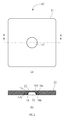
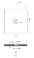
まず、図1を参照しながら、第一実施形態に係る防振パッドについて説明する。図1は、第一実施形態に係る防振パッドの構成を示す図であり、図1(a)が、防振パッドの平面図、図1(b)が、図1(a)のA−A線による断面図である。
Hereinafter, an anti-vibration pad according to an embodiment of the present invention will be described with reference to the drawings.
(First embodiment)
First, the vibration isolating pad according to the first embodiment will be described with reference to FIG. FIG. 1 is a diagram illustrating a configuration of a vibration isolation pad according to the first embodiment, in which FIG. 1A is a plan view of the vibration isolation pad, and FIG. 1B is A- in FIG. It is sectional drawing by A line.
図1に示すように、防振パッド10は、略正方形の板状をしており、弾性材料から形成された弾性シート11、金属製の筒状補強部材15、リング19を備えている。弾性シート11は、粘着性のある合成樹脂から形成されており、本実施形態では、透明なシリコーンゲルが使用されている。
As shown in FIG. 1, the
筒状補強部材15は、全体として略円筒形状をした補強部材であり、小径の上側円筒部17a、大径の下側円筒部17bとを有している。また、筒状補強部材15の上部には、小径の円形開口が形成された上面部16aが形成され、下部には、大径の円形開口が形成された下面部16bが形成されている。
The cylindrical reinforcing
また、筒状補強部材15の上側円筒部17aと下側円筒部17bとの境界には、上側円筒部17aの下端と下側円筒部17bの上端とを水平につなぐ、円帯状の中間段面部16cが形成されている。本実施形態における筒状補強部材15の材料は、ステンレスである。
Further, an annular intermediate step surface portion that horizontally connects the lower end of the upper
リング19は、金属製リングであり、本実施形態では真鍮から形成されている。リング19は、筒状補強部材15の下側円筒部17bの内側に設置されており、下側円筒部17bの内径よりも小さい外径である。
The
また、防振パッド10には、筒状補強部材15の内部において、底面から上面部16aの下端部分にかけて、弾性シート11の存在しない円錐台形状の中空部13が形成されている。中空部13の底面は、下面部16bの円形開口と略同じ径の円形であり、中空部13の上面は、上面部16aの円形開口と略同じ径の円形となっている。
Further, the
防振パッド10が重量物の下に敷かれると、重量物下面と、重量物が設置されている基台上面との間に挟まれることになり、重量物下面によって筒状補強部材15の上部開口が塞がれ、基台上面によって筒状補強部材15の下部開口が塞がれることになる。
When the
ここで、弾性シート11を構成する合成樹脂が筒状補強部材15の内部に隙間無く充填されていると、合成樹脂の収縮率(寸法変化)は非常に小さいため、重量物に作用する振動を吸収しようとして金属製の筒状補強部材15が変形しようとしても、内部に充填されている合成樹脂の逃げ場がない。すなわち、筒状補強部材15がその内部の体積を減らす方向に変形する、すなわち、筒状補強部材15が内側に変形することができなくなってしまう。
Here, when the synthetic resin constituting the
これでは、防振パッド10の防振機能を発揮することができない。これに対して、本実施形態のように筒状補強部材15の内部に隙間である中空部13を形成しておけば、筒状補強部材15が内側に変形する際に移動する合成樹脂の逃げ場となり、筒状補強部材15の変形により振動を吸収することが可能となる。
With this, the anti-vibration function of the
次に、防振パッド10の製造方法について、説明する。まず、筒状補強部材15をプレス加工(塑性変形加工)により成形する。具体的には、プレス金型を用いて、金属製プレートをプレス加工(絞り加工)し、略円筒形状の筒状補強部材15を成形する。
Next, a method for manufacturing the
続いて、別容器内に筒状補強部材15をセットし、シリコーンゲル材料を注入し硬化させる。ここで、この容器には、上述した中空部13を形成するための突起部が形成されており、この突起部が存在する領域には、シリコーンゲルが流れることができない。
Subsequently, the cylindrical reinforcing
したがって、シリコーンゲルの硬化後に防振パッド10を取り出せば、中空部13が形成された防振パッド10が完成する。なお、防振パッド10のサイズは、対象重量物の形状や設置環境に合わせて適宜変更できるが、例えば、一辺が50mm、厚さ4mmとする。
Therefore, if the
以上、詳細に説明した防振パッド10によれば、小型重量物の下に敷くことで、地震等の発生の際に重量物に作用する振動を吸収し、転倒を防止することが可能となる。具体的には、防振パッド10は、硬質材料から形成された筒状補強部材15を備えることで、重量物の荷重により弾性シート11がつぶれてしまうのを防止し、安定して重量物を支えながら振動を吸収することができる。
As described above, according to the
また、本実施形態では、内部に中空部13が形成された筒状補強部材15を備えることで、筒状補強部材15内に充填された合成樹脂によって筒状補強部材15が変形できなくなるのを防止し、荷重に応じて筒状補強部材15が変形することで、安定して重量物を支えながら振動を吸収することができる。
Further, in the present embodiment, by providing the cylindrical reinforcing
また、本実施形態では、筒状補強部材15に中間段面部16cが形成され、上面部16aと合わせて、重量物を支持するための支持部(面)が異なる高さで二段設けられており、幅広い重さの重量物に適切に対応可能である。例えば、比較的軽い重量物の場合には、最も高い上面部16aだけで重量物が支えられる。一方、重量物が重くなるに従って、筒状補強部材15が変形し、重量物が中間段面部16cの高さに下降するまで凹むと、上面部16aに加えて中間段面部16cによっても重量物が支えられることになる。
Moreover, in this embodiment, the intermediate | middle
また、筒状補強部材15が頑丈すぎて、重量物が筒状補強部材15のみによって支えられてしまうと、弾性シート11により重量物を支えることができなくなり、弾性シート11による振動の吸収ができなくなってしまう。これに対して、本実施形態では、段階的に高さが異なる支持部(上面部16a,中間段面部16c)を複数段形成することで、荷重に応じて重量物を支持する支持部が選択的に使用されるので、幅広い重さの重量物に対して、弾性シート11の支持による振動吸収作用を発揮させることができる。
If the
さらに、段階的に高さが異なる複数の支持部16a,16cが形成されていることで、防振パッド10を使って重量物の傾き調整を行うことも可能である。例えば、墓石を設置する際には、土台の上に竿石を設置するが、そのまま竿石を設置しただけでは竿石が傾いている場合も多いので、従来は、スペーサーを挟んで竿石を叩くなどして傾き調整が行われていた。
Furthermore, since the plurality of
これに対して、防振パッド10を竿石の下の四隅に敷いておけば、低く調整したい側を叩くことで、段階的に筒状補強部材15を変形させて高さ調整を行うことができるので、竿石の傾きを調整することができる。なお、墓石に防振パッド10を使用する際には、新設の墓石に使用することもできるし、既存の墓石の耐震性向上や傾き修正に用いることもできる。
On the other hand, if the
また、本実施形態では、筒型補強部材15をプレス加工による塑性変形により形成しているので、筒型補強部材15の強度が高く、丈夫な防振パッド10を提供することができる。ダイカストで鋳造方式により製造した場合には、塑性変形により製造した場合と比較してせん断強度が低くなるため、重量物の荷重が大きくなった場合に破断するおそれもあるが、プレス加工によれば、高いせん断強度を実現できる。
Further, in the present embodiment, since the cylindrical reinforcing
また、本実施形態に係る筒状補強部材15は、重量物の支持部となる上面部16a及び中間段面部16cが点ではなく面となっており、重量物を面で支えることで、安定した支持が可能となる。
Moreover, the
また、本実施形態においては、弾性シート11を粘着性のあるゲル材料から形成しており、防振パッド10をセットする際の作業を容易に行うことができる。弾性シート11は、防振パッド10の底面の大部分に設置されており、防振パッド10を重量物の下に配置するにあたって、土台となる下側構造物の上面に置けば、防振パッド10と下側構造物とが弾性シート11により強固に接着される。
Moreover, in this embodiment, the
したがって、その後重量物を設置する際に、防振パッド10に何かが接触してしまって所望の設置場所からずれてしまうといったことを防止できる。なお、防振バッド10を設置する際には、接着剤を併用すれば、防振パッド10と構造物との接着性をさらに高めて耐震性をより高めることができる。
Therefore, when a heavy object is subsequently installed, it can be prevented that something touches the
また、本実施形態においては、筒状補強部材15の下側円筒部17bの内部に金属製のリング19が設置されており、筒状補強部材15が変形して上面部16aが下方に下がって来ても、このリング19の存在により、それ以上の変形を阻止することができる。これにより、防振パッド10が完全につぶれることを防止し、大きな地震がきた場合であっても、防振パッドの防振機能を最低限確保することが可能となる。
Further, in the present embodiment, a
以上、本実施形態について詳細に説明したが、本実施形態は、本発明の主旨を逸脱しない範囲内で種々の変形が可能である。例えば、弾性シート11の材料としては、シリコーンゲルに限らず、その他の高分子ゲル、ゴム等、他の弾性材料を適宜使用することができる。もちろん粘着性が無い材料であっても良い。
Although the present embodiment has been described in detail above, the present embodiment can be variously modified without departing from the gist of the present invention. For example, the material of the
また、筒状補強部材15の材料としても、ステンレス以外のアルミ、真鍮、銅合金等の他の金属や、熱可塑性樹脂等の硬質樹脂等、変形可能な筒状補強部材15を構成できる硬質材料であれば、適宜他の材料を使用することができる。また、リング19の材料も筒状補強部材15と同様に適宜他の硬質材料を用いることができる。
Further, as the material of the cylindrical reinforcing
また、筒状補強部材15の形状は、円筒形状に限らず、全体として角筒形状であっても良く、内部を覆う周壁(側壁)が形成された筒部を有し、重量物を支持するための支持部が多段に形成された筒状補強部材であれば良い。また、周壁が斜めになった斜筒でも良いし、支持部が面ではなく線や点であっても良い。
Moreover, the shape of the cylindrical reinforcing
また、上記実施形態では、重量物を支持するための支持部(上面部16a,中間段面部16c)が二段に設けられているが、三段以上の複数段に設けられても良い。また、上記実施形態では、上面部16a及び下面部16bの双方に円形開口が設けられているが、中空部13が合成樹脂の逃げ場となるため、開口を形成しなくても良い。但し、大きな重量物に対応するためには、筒状補強部材15の外部に合成樹脂が移動できるように、上面部16a及び下面部16bの少なくとも一方に開口を形成したほうが良い。
Moreover, in the said embodiment, although the support part (
また、リング19の形状もリング状に限らず、筒状補強部材15の内部に位置して筒状補強部材15が完全につぶれてしまうのを防止することのできるスペーサーとして機能できる形状であれば、円盤形状や角柱形状であっても良い。
Further, the shape of the
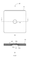
続いて、第一実施形態の変形例1について、図2を参照しながら説明する。図2は、第一実施形態の変形例1に係る防振パッドの構成を示す図であり、図2(a)が、防振パッドの平面図、図2(b)が、図2(a)のB−B線による断面図である。 Next, Modification 1 of the first embodiment will be described with reference to FIG. FIG. 2 is a diagram illustrating a configuration of a vibration isolation pad according to the first modification of the first embodiment. FIG. 2A is a plan view of the vibration isolation pad, and FIG. 2B is FIG. It is sectional drawing by the BB line of FIG.
本変形例に係る防振パッド10’は、上記防振パッド10と略同じ構成であるため、同じ部材には同じ番号を付し、説明を省略する。本変形例では、筒状補強部材15’の構成が上記実施形態と異なっており、上面部16a’に上部開口が形成されておらず、筒状補強部材15’の上部が閉じた構成となっている。
The
本変形例によれば、上記実施形態と同様の作用効果を奏することができると共に、筒状補強部材15’の上部が閉じていることで、上記実施形態よりも内部の合成樹脂が外部に移動し難く、この分だけ筒状補強部材15’が内側に変形しに難くなる。よって、本変形例に係る防振パッド10’は、上記実施形態よりも大きい重量物への使用に適している。
According to this modified example, the same operational effects as the above embodiment can be obtained, and the upper portion of the cylindrical reinforcing
(第二実施形態)
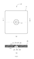
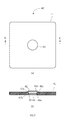
次に、図3を参照しながら、第二実施形態に係る防振パッドについて説明する。図3は、第二実施形態に係る防振パッドの構成を示す図であり、図3(a)が、防振パッドの平面図、図3(b)が、図3(a)のC−C線による断面図である。
(Second embodiment)
Next, an anti-vibration pad according to the second embodiment will be described with reference to FIG. 3A and 3B are diagrams showing the configuration of the vibration-proof pad according to the second embodiment. FIG. 3A is a plan view of the vibration-proof pad, and FIG. It is sectional drawing by a C line.
図3に示すように、防振パッド20は、略正方形の板状をしており、弾性材料から形成された弾性シート21、金属製の筒状補強部材25、リング29を備えている。防振パッド20は、上記第一実施形態に係る防振パッド10と共通する構成を多数有しており、同様の構成については詳細な説明を省略する。
As shown in FIG. 3, the
第二実施形態において、弾性シート21、筒状補強部材25及びリング29は、上記第一実施形態の弾性シート11、筒状補強部材15及びリング19にそれぞれ対応するが、第一実施形態とは弾性シート21の形状が若干異なる。すなわち、本実施形態では、筒状補強部材25内の弾性シート21が存在しない場所である中空部23が上下に分かれている。筒状補強部材25の上面部26aの円形開口付近に上側中空部23a、筒状補強部材25の下面部26bの円形開口付近に下側中空部23bが形成されている。
In the second embodiment, the
第二実施形態に係る防振パッド20の製造方法も上記第一実施形態と同様である。但し、上側及び下側の中空部23a,23bを形成するために、シリコーンゲルを注入し硬化させる際の容器に上下二つ突起部を形成しておく必要がある。
The manufacturing method of the
また、第二実施形態においても、第一実施形態と同様に、本発明の主旨を逸脱しない範囲内で種々の変形が可能である。以上、第二実施形態によれば、第一実施形態と同様の作用効果を奏し、小型重量物の下に敷くことで、地震等の発生の際に振動を吸収し、転倒を防止することが可能となる。なお、本実施形態では、第一実施形態と比較して中空部23の体積がやや小さいので、第一実施形態に係る防振パッド10よりは、比較的大きい重量物への使用に適している。
Also in the second embodiment, various modifications can be made without departing from the gist of the present invention, as in the first embodiment. As described above, according to the second embodiment, the same effects as the first embodiment can be obtained, and by laying under a small heavy object, vibration can be absorbed in the event of an earthquake or the like, and a fall can be prevented. It becomes possible. In addition, in this embodiment, since the volume of the hollow part 23 is a little small compared with 1st embodiment, it is suitable for the use to a comparatively big heavy article rather than the
(第三実施形態)
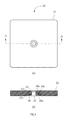
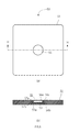
次に、図4を参照しながら、第三実施形態に係る防振パッドについて説明する。図4は、第三実施形態に係る防振パッドの構成を示す図であり、図4(a)が、防振パッドの平面図、図4(b)が、図4(a)のD−D線による断面図である。
(Third embodiment)
Next, the vibration isolating pad according to the third embodiment will be described with reference to FIG. 4A and 4B are diagrams showing the configuration of the vibration-proof pad according to the third embodiment. FIG. 4A is a plan view of the vibration-proof pad, and FIG. It is sectional drawing by D line.
図4に示すように、防振パッド30は、略正方形の板状をしており、弾性材料から形成された弾性シート31、金属製の筒状補強部材35、リング39を備えている。防振パッド30は、上記第一実施形態に係る防振パッド10と共通する構成を多数有しており、同様の構成については詳細な説明を省略する。
As shown in FIG. 4, the
第三実施形態において、弾性シート31、筒状補強部材35及びリング39は、上記第一実施形態の弾性シート11、筒状補強部材15及びリング19にそれぞれ対応するが、第一実施形態とは弾性シート31の形状が若干異なる。すなわち、本実施形態では、筒状補強部材35内の弾性シート31が存在しない部分である中空部33が弾性シート31の下方から上方まで円柱状に貫通して形成されている。
In the third embodiment, the
また、中空部33は、筒状補強部材35の上面部36aの円形開口と略同じ直径の円柱形状であるが、中空部33の上端は、筒状補強部材35の上側円筒部37aよりも若干小さい開口となるように広げられ、中空部33の下端は、筒状補強部材35の下側円筒部37bよりも若干小さい開口となるように広げられている。
The
第二実施形態に係る防振パッド30の製造方法も上記第一実施形態と同様である。但し、上下に貫通した中空部33を形成するために、シリコーンゲルを注入して硬化させる際の容器に、上下につながる突起部を形成する必要がある。
The manufacturing method of the
また、第三実施形態においても、第一実施形態と同様に、本発明の主旨を逸脱しない範囲内で種々の変形が可能である。以上、第三実施形態によれば、第一実施形態と同様の作用効果を奏し、小型重量物の下に敷くことで、地震等の発生の際に振動を吸収し、転倒を防止することが可能となる。 In the third embodiment, various modifications can be made without departing from the gist of the present invention, as in the first embodiment. As described above, according to the third embodiment, the same effects as the first embodiment can be obtained, and by laying under a small heavy object, vibration can be absorbed in the event of an earthquake or the like, and a fall can be prevented. It becomes possible.
続いて、第三実施形態の変形例1について、図5を参照しながら説明する。図5は、第三実施形態の変形例1に係る防振パッドの構成を示す図であり、図5(a)が、防振パッドの平面図、図5(b)が、図5(a)のE−E線による断面図である。 Next, Modification 1 of the third embodiment will be described with reference to FIG. 5A and 5B are diagrams showing the configuration of the vibration isolation pad according to the first modification of the third embodiment. FIG. 5A is a plan view of the vibration isolation pad, and FIG. It is sectional drawing by the EE line | wire of ().
本変形例に係る防振パッド30’は、上記防振パッド30と略同じ構成であるため、同じ部材には同じ番号を付し、説明を省略する。本変形例では、筒状補強部材35’の構成が上記実施形態と異なっており、上面部36a’に上部開口が形成されておらず、筒状補強部材35’の上部が閉じた構成となっている。
The
本変形例によれば、上記実施形態と同様の作用効果を奏することができると共に、筒状補強部材35’の上部が閉じていることで、上記実施形態よりも内部の合成樹脂が外部に移動し難く、この分だけ筒状補強部材35’が内側に変形しに難くなる。よって、本変形例に係る防振パッド30’は、上記実施形態よりも大きい重量物への使用に適している。
According to this modification, the same operational effects as in the above embodiment can be obtained, and the upper portion of the cylindrical reinforcing member 35 'is closed, so that the synthetic resin inside moves outside as compared to the above embodiment. This makes it difficult to deform the cylindrical reinforcing member 35 'inward. Therefore, the
(第四実施形態)
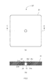
次に、図6を参照しながら、第四実施形態に係る防振パッドについて説明する。図6は、第四実施形態に係る防振パッドの構成を示す図であり、図6(a)が、防振パッドの平面図、図6(b)が、図6(a)のF−F線による断面図である。
(Fourth embodiment)
Next, an anti-vibration pad according to a fourth embodiment will be described with reference to FIG. 6A and 6B are diagrams illustrating the configuration of the vibration isolation pad according to the fourth embodiment. FIG. 6A is a plan view of the vibration isolation pad, and FIG. 6B is an F- It is sectional drawing by F line.
図6に示すように、防振パッド40は、略正方形の板状をしており、弾性材料から形成された弾性シート41、金属製の筒状補強部材45、リング49を備えている。防振パッド40は、上記第一実施形態に係る防振パッド10と共通する構成を多数有しており、同様の構成については詳細な説明を省略する。
As shown in FIG. 6, the
第四実施形態において、弾性シート41、筒状補強部材45及びリング49は、上記第一実施形態の弾性シート11、筒状補強部材15及びリング19にそれぞれ対応するが、第一実施形態とは弾性シート41の形状が若干異なる。
In the fourth embodiment, the
すなわち、本実施形態では、筒状補強部材45内に弾性シート41が一切存在しておらず、筒状補強部材45内部が全て中空部43になっている。また、第四実施形態では、弾性シート41の高さが、筒状補強部材45の高さよりも若干低くなっている。
That is, in this embodiment, the
第四実施形態に係る防振パッド40の製造方法も上記第一実施形態と同様である。但し、筒状補強部材45を容器内にセットしてシリコーンゲルを注入する際には、筒状補強部材45内にシリコーンゲルが入らないように、筒状補強部材45の外側にだけ注入するようにしなければならない。
The manufacturing method of the
また、第四実施形態においても、第一実施形態と同様に、本発明の主旨を逸脱しない範囲内で種々の変形が可能である。以上、第四実施形態によれば、第一実施形態と同様の作用効果を奏し、小型重量物の下に敷くことで、地震等の発生の際に振動を吸収し、転倒を防止することが可能となる。特に、本実施形態では、筒状補強部材45の内部が全て中空となっていることで、筒状補強部材45が内側に変形しやすくなっているため、比較的小型の重量物への使用に適している。
Also in the fourth embodiment, as in the first embodiment, various modifications can be made without departing from the gist of the present invention. As described above, according to the fourth embodiment, the same effects as the first embodiment can be achieved, and by laying under a small heavy object, vibration can be absorbed in the event of an earthquake or the like, and a fall can be prevented. It becomes possible. In particular, in this embodiment, since the inside of the cylindrical reinforcing
続いて、第四実施形態の変形例1について、図7を参照しながら説明する。図7は、第四実施形態の変形例1に係る防振パッドの構成を示す図であり、図7(a)が、防振パッドの平面図、図7(b)が、図7(a)のG−G線による断面図である。 Subsequently, Modification 1 of the fourth embodiment will be described with reference to FIG. 7A and 7B are diagrams showing the configuration of the vibration isolation pad according to the first modification of the fourth embodiment. FIG. 7A is a plan view of the vibration isolation pad, and FIG. 7B is FIG. It is sectional drawing by the GG line of FIG.
本変形例に係る防振パッド40’は、上記防振パッド40と略同じ構成であるため、同じ部材には同じ番号を付し、説明を省略する。本変形例では、筒状補強部材45’の構成が上記実施形態と異なっており、上面部46a’に上部開口が形成されておらず、筒状補強部材45’の上部が閉じた構成となっている。本変形例によれば、上記実施形態と同様の作用効果を奏することができる。
Since the anti-vibration pad 40 'according to the present modification has substantially the same configuration as the
(第五実施形態)
次に、図8を参照しながら、第五実施形態に係る防振パッドについて説明する。図8は、第五実施形態に係る防振パッドの構成を示す図であり、図8(a)が、防振パッドの平面図、図8(b)が、図8(a)のH−H線による断面図である。
(Fifth embodiment)
Next, an anti-vibration pad according to a fifth embodiment will be described with reference to FIG. FIG. 8 is a diagram showing the configuration of the vibration isolation pad according to the fifth embodiment. FIG. 8A is a plan view of the vibration isolation pad, and FIG. 8B is an H- It is sectional drawing by H line.
図8に示すように、防振パッド50は、略正方形の板状をしており、弾性材料から形成された弾性シート51、金属製の筒状補強部材55を備えている。防振パッド50は、上記第一実施形態に係る防振パッド10と共通する構成を多数有しており、同様の構成については詳細な説明を省略する。
As shown in FIG. 8, the vibration-
第五実施形態において、弾性シート51及び筒状補強部材55は、上記第一実施形態の弾性シート11及び筒状補強部材15にそれぞれ対応するが、第一実施形態とは、弾性シート51及び筒状補強部材55の形状が若干異なる。
In the fifth embodiment, the
本実施形態に係る筒状補強部材55は、二段の支持部が設けられている点で第一実施形態と共通するが、上面部56aが閉じられた形状になっている点、下側円筒部57bが、側壁が内側に傾斜した円錐台(斜筒)状となっている点、下面部56bが外側に向けて延在している点で第一実施形態と異なる。弾性シート51は、中空部53が上側円筒部57aの内側にのみ形成されている点、筒状補強部材55の内部51aが外側とは違う材料で形成されている点で第一実施形態と異なる。
The cylindrical reinforcing
この弾性シート51の筒状補強部材55の内部51aの材料としては、弾性シート51の他の部分の材料であるシリコーンゲルよりもゴム硬度、反発弾性率、振動吸収率の高い材料であるブチルゴム(IIR)が用いられる。このように、内部51aの材料を適宜変えることで、様々な性能の防振パッド50を提供することができ、種々の重量物に対応することが可能となる。
As a material of the inside 51a of the cylindrical reinforcing
第五実施形態に係る防振パッド50の製造方法も上記第一実施形態と同様であるが、中空部53を上側円筒部57aの内側のみに形成するために、合成樹脂の注入・硬化工程を二回に分けて行う必要があると共に、筒状補強部材55の内側と外側とで異なる材料を注入する必要がある。
The manufacturing method of the
また、第五実施形態においても、第一実施形態と同様に、本発明の主旨を逸脱しない範囲内で種々の変形が可能である。筒状補強部材55の内側と外側とで異なる弾性シート51の材料の組合せも適宜変更可能であり、本実施形態とは逆に内側51aを軟らかい材料としても良い。以上、第五実施形態によれば、第一実施形態と同様の作用効果を奏し、小型重量物の下に敷くことで、地震等の発生の際に振動を吸収し、転倒を防止することが可能となる。
Also in the fifth embodiment, various modifications can be made without departing from the gist of the present invention, as in the first embodiment. The combination of materials of the
特に、第五実施形態では、筒状補強部材55の上面が閉じていると共に、中空部53の容積が比較的小さく、また、筒状補強部材55の内部に硬い合成樹脂材料を配置しているので、他の実施形態と比較して筒状補強部材55が内側に変形し難い。よって、本実施形態に係る防振パッド55は、比較的大型の重量物への使用に適している。
In particular, in the fifth embodiment, the upper surface of the cylindrical reinforcing
(第六実施形態)
次に、図9を参照しながら、第六実施形態に係る防振パッドについて説明する。図9は、第六実施形態に係る防振パッドの構成を示す図であり、図9(a)が、防振パッドの平面図、図9(b)が、図9(a)のI−I線による断面図である。
(Sixth embodiment)
Next, an anti-vibration pad according to the sixth embodiment will be described with reference to FIG. 9A and 9B are diagrams showing the configuration of the vibration isolation pad according to the sixth embodiment. FIG. 9A is a plan view of the vibration isolation pad, and FIG. It is sectional drawing by I line.
図9に示すように、防振パッド60は、略正方形の板状をしており、弾性材料から形成された弾性シート61、金属製の筒状補強部材65を備えている。防振パッド60は、上記第一実施形態に係る防振パッド10と共通する構成を多数有しており、同様の構成については詳細な説明を省略する。
As shown in FIG. 9, the vibration-
第六実施形態において、弾性シート61及び筒状補強部材65は、上記第一実施形態の弾性シート11及び筒状補強部材15にそれぞれ対応するが、第一実施形態とは、弾性シート61及び筒状補強部材65の形状が若干異なる。
In the sixth embodiment, the
本実施形態に係る筒状補強部材65は、重量物の支持部が上面66aだけの一段となっている点、円筒部67が、側壁が内側に傾斜した円錐台(斜筒)状となっている点、下面部66bが外側に向けて延在している点で第一実施形態と異なる。弾性シート61は、中空部63が円筒部67の略下側半分にのみ形成されている点、筒状補強部材65の内部61aが外側とは違う材料で形成されている点で第一実施形態と異なる。
In the cylindrical reinforcing
この弾性シート61の筒状補強部材65の内部61aの材料としては、弾性シート61の他の部分の材料であるシリコーンゲルよりもゴム硬度、反発弾性率、振動吸収率の高い材料であるブチルゴム(IIR)が用いられる。このように、内部61aの材料を適宜変えることで、様々な性能の防振パッド60を提供することができ、種々の重量物に対応することが可能となる。
As a material of the inside 61a of the cylindrical reinforcing
第六実施形態に係る防振パッドの製造方法も上記第一実施形態と同様であるが、合成樹脂の注入・硬化工程において、筒状補強部材65の内側と外側とで異なる材料を注入する必要がある。また、第六実施形態においても、第一実施形態と同様に、本発明の主旨を逸脱しない範囲内で種々の変形が可能である。
The manufacturing method of the vibration-proof pad according to the sixth embodiment is the same as that of the first embodiment, but it is necessary to inject different materials between the inside and the outside of the cylindrical reinforcing
筒状補強部材65の内側と外側とで異なる弾性シート61の材料の組合せも適宜変更可能であり、本実施形態とは逆に内側61aを軟らかい材料としても良い。以上、第六実施形態によれば、第一実施形態と同様の作用効果を奏し、小型重量物の下に敷くことで、地震等の発生の際に振動を吸収し、転倒を防止することが可能となる。
The combination of materials of the
以上、変形例も含めて本発明の実施の形態について説明したが、筒状補強部材の形状や、筒状補強部材内の弾性材料の量を変えて中空部の容積を調節することで、幅広い重さの重量物に対応できる防振パッドを提供することができる。 As mentioned above, although embodiment of this invention was described including a modification, it is wide by adjusting the volume of a hollow part by changing the quantity of the elastic material in the shape of a cylindrical reinforcement member, and a cylindrical reinforcement member. It is possible to provide an anti-vibration pad that can handle heavy objects.
ここで、筒状補強部材が大きくつぶれるのを防止し、合成樹脂による振動吸収機能を発揮させるためには、筒状補強部材の内部にある程度の合成樹脂が存在することが望ましく、一方、筒状補強部材の変形を可能にするためには筒状補強部材の内部にある程度の中空部を形成する必要がある。これらを鑑みると、筒状補強部材内の中空部は、筒状補強部材内の容積の1/5以上であって4/5以下であればより望ましい。 Here, in order to prevent the cylindrical reinforcing member from being largely crushed and to exhibit a vibration absorbing function by the synthetic resin, it is desirable that a certain amount of synthetic resin exists inside the cylindrical reinforcing member, In order to allow deformation of the reinforcing member, it is necessary to form a certain amount of hollow portion inside the cylindrical reinforcing member. In view of these, the hollow portion in the cylindrical reinforcing member is more preferably 1/5 or more and 4/5 or less of the volume in the cylindrical reinforcing member.
10,20,30,40,50,60 防振パッド
11,21,31,41,51,61 弾性シート
13,23,33、43,53,63 中空部
15,25,35,45,55,65 筒状補強部材
16,26,36,46,56,66 面部
17,27,37,47,57,67 円筒部
19,29,39,49 リング
10, 20, 30, 40, 50, 60
上記課題を解決するために、本発明に係る防振パッドは、重量物の転倒を防止するために前記重量物の下に敷かれる防振パッドにおいて、弾性材料からなる弾性シートと、前記弾性シートを補強するために前記弾性シートと一体に設置されると共に、周壁により内部を囲う筒部を有して硬質材料から形成された筒状補強部材であって、前記重量物の荷重を受ける支持部が複数段形成されている筒状補強部材と、を備え、前記筒状補強部材の内部に、前記弾性シートが存在しない中空部が形成されていることを特徴とする。
In order to solve the above-described problem, the vibration isolating pad according to the present invention includes an elastic sheet made of an elastic material in the vibration isolating pad laid under the heavy load to prevent the heavy load from overturning, and the elastic sheet. A cylindrical reinforcing member that is integrally formed with the elastic sheet to reinforce the outer periphery and that is formed of a hard material having a cylindrical portion that surrounds the inside by a peripheral wall , and that receives a load of the heavy object And a cylindrical reinforcing member formed in a plurality of stages , and a hollow portion in which the elastic sheet does not exist is formed inside the cylindrical reinforcing member.
Claims (5)
弾性材料からなる弾性シートと、
前記弾性シートを補強するために前記弾性シートと一体に設置されると共に、周壁により内部を囲う筒部を有して硬質材料から形成された筒状補強部材と、を備え、
前記筒状補強部材の内部に、前記弾性シートが存在しない中空部が形成されていることを特徴とする防振パッド。 In the vibration-proof pad laid under the heavy load to prevent the heavy load from falling,
An elastic sheet made of an elastic material;
In order to reinforce the elastic sheet, it is installed integrally with the elastic sheet, and includes a cylindrical reinforcing member formed of a hard material having a cylindrical portion surrounding the inside by a peripheral wall,
A vibration-proof pad, wherein a hollow portion where the elastic sheet does not exist is formed inside the cylindrical reinforcing member.
Priority Applications (1)
| Application Number | Priority Date | Filing Date | Title |
|---|---|---|---|
| JP2010294361A JP4730978B1 (en) | 2010-12-29 | 2010-12-29 | Anti-vibration pad |
Applications Claiming Priority (1)
| Application Number | Priority Date | Filing Date | Title |
|---|---|---|---|
| JP2010294361A JP4730978B1 (en) | 2010-12-29 | 2010-12-29 | Anti-vibration pad |
Related Child Applications (1)
| Application Number | Title | Priority Date | Filing Date |
|---|---|---|---|
| JP2011067513A Division JP2012141054A (en) | 2011-03-25 | 2011-03-25 | Vibration absorbing pad |
Publications (2)
| Publication Number | Publication Date |
|---|---|
| JP4730978B1 JP4730978B1 (en) | 2011-07-20 |
| JP2012141015A true JP2012141015A (en) | 2012-07-26 |
Family
ID=44461711
Family Applications (1)
| Application Number | Title | Priority Date | Filing Date |
|---|---|---|---|
| JP2010294361A Active JP4730978B1 (en) | 2010-12-29 | 2010-12-29 | Anti-vibration pad |
Country Status (1)
| Country | Link |
|---|---|
| JP (1) | JP4730978B1 (en) |
Cited By (2)
| Publication number | Priority date | Publication date | Assignee | Title |
|---|---|---|---|---|
| JP2012013220A (en) * | 2010-08-26 | 2012-01-19 | Yasuteru Saeki | Vibration isolation pad |
| JP2018071555A (en) * | 2016-10-24 | 2018-05-10 | 株式会社安震 | Vibration control pad |
Citations (8)
| Publication number | Priority date | Publication date | Assignee | Title |
|---|---|---|---|---|
| JPH03121815A (en) * | 1989-10-04 | 1991-05-23 | K F C:Kk | Kneading-force feeding apparatus for mortar or the like |
| JPH03142382A (en) * | 1989-10-30 | 1991-06-18 | Sharp Corp | Characteristic measuring instrument for high frequency device |
| JPH0442939U (en) * | 1990-08-09 | 1992-04-13 | ||
| JPH05257485A (en) * | 1992-03-13 | 1993-10-08 | Railway Technical Res Inst | Magnetic composite type vibration damping material and installation of magnetic composite type vibration damping material |
| JPH0690506A (en) * | 1992-09-08 | 1994-03-29 | Toyota Motor Corp | Cooling device for semiconductor control element for electric motorcar |
| JPH0835528A (en) * | 1994-07-26 | 1996-02-06 | Mitsubishi Motors Corp | Clutch structure |
| JP2008255975A (en) * | 2007-03-12 | 2008-10-23 | Uchiyama Mfg Corp | Vibration damping washer |
| JP2009174666A (en) * | 2008-01-25 | 2009-08-06 | Seiwa Electric Mfg Co Ltd | Vibration isolating member with electricity-conducting function and mechanical apparatus including the same |
-
2010
- 2010-12-29 JP JP2010294361A patent/JP4730978B1/en active Active
Patent Citations (8)
| Publication number | Priority date | Publication date | Assignee | Title |
|---|---|---|---|---|
| JPH03121815A (en) * | 1989-10-04 | 1991-05-23 | K F C:Kk | Kneading-force feeding apparatus for mortar or the like |
| JPH03142382A (en) * | 1989-10-30 | 1991-06-18 | Sharp Corp | Characteristic measuring instrument for high frequency device |
| JPH0442939U (en) * | 1990-08-09 | 1992-04-13 | ||
| JPH05257485A (en) * | 1992-03-13 | 1993-10-08 | Railway Technical Res Inst | Magnetic composite type vibration damping material and installation of magnetic composite type vibration damping material |
| JPH0690506A (en) * | 1992-09-08 | 1994-03-29 | Toyota Motor Corp | Cooling device for semiconductor control element for electric motorcar |
| JPH0835528A (en) * | 1994-07-26 | 1996-02-06 | Mitsubishi Motors Corp | Clutch structure |
| JP2008255975A (en) * | 2007-03-12 | 2008-10-23 | Uchiyama Mfg Corp | Vibration damping washer |
| JP2009174666A (en) * | 2008-01-25 | 2009-08-06 | Seiwa Electric Mfg Co Ltd | Vibration isolating member with electricity-conducting function and mechanical apparatus including the same |
Cited By (2)
| Publication number | Priority date | Publication date | Assignee | Title |
|---|---|---|---|---|
| JP2012013220A (en) * | 2010-08-26 | 2012-01-19 | Yasuteru Saeki | Vibration isolation pad |
| JP2018071555A (en) * | 2016-10-24 | 2018-05-10 | 株式会社安震 | Vibration control pad |
Also Published As
| Publication number | Publication date |
|---|---|
| JP4730978B1 (en) | 2011-07-20 |
Similar Documents
| Publication | Publication Date | Title |
|---|---|---|
| EP2894365B1 (en) | Seismic base isolation device | |
| JP4730978B1 (en) | Anti-vibration pad | |
| JP5244244B2 (en) | Vibration isolator | |
| JP2012141054A (en) | Vibration absorbing pad | |
| JP4606516B1 (en) | Anti-vibration pad | |
| KR20060131254A (en) | Prop of dual flooring and method manufacturing and using thereof | |
| JP5542581B2 (en) | Anti-vibration pad | |
| JPS62101937A (en) | Improvement of hydraulic type shock-absorbing supporter | |
| JP2003118818A (en) | Vibration damping rack and rack vibration damping method | |
| JP2016223586A (en) | Lamination rubber support | |
| JP4511420B2 (en) | Dynamic damper | |
| JP5330463B2 (en) | Elastic body restraint degree variable structure | |
| JP3142382U (en) | Fall-prevention equipment and fall-prevented structures | |
| JP2018132175A (en) | Upper support | |
| CN103225663B (en) | Vibration control equipment | |
| JP6594050B2 (en) | Seismic isolation device mounting structure | |
| CN201292579Y (en) | Stiffness changing composite lead core rubber support shock isolator | |
| CN209894325U (en) | Sucking disc formula rubber shock pad reaches electronic scale including it | |
| JP2003313883A (en) | Base isolating apparatus and base isolation structure | |
| JP7382867B2 (en) | Support structure of the building body | |
| CN101457555A (en) | Stiffness changing composite lead core rubber support shock isolator | |
| JP2017187055A (en) | Seismic isolator with concentric circle laminated attenuation materials | |
| JP6389604B2 (en) | Elastic washers and building foundations using them | |
| JP7386735B2 (en) | Support structure of the building body | |
| CN211083604U (en) | High-performance square tube |
Legal Events
| Date | Code | Title | Description |
|---|---|---|---|
| A131 | Notification of reasons for refusal |
Free format text: JAPANESE INTERMEDIATE CODE: A131 Effective date: 20110307 |
|
| A975 | Report on accelerated examination |
Free format text: JAPANESE INTERMEDIATE CODE: A971005 Effective date: 20110303 |
|
| A521 | Request for written amendment filed |
Free format text: JAPANESE INTERMEDIATE CODE: A523 Effective date: 20110325 |
|
| TRDD | Decision of grant or rejection written | ||
| A01 | Written decision to grant a patent or to grant a registration (utility model) |
Free format text: JAPANESE INTERMEDIATE CODE: A01 Effective date: 20110414 |
|
| A01 | Written decision to grant a patent or to grant a registration (utility model) |
Free format text: JAPANESE INTERMEDIATE CODE: A01 |
|
| A61 | First payment of annual fees (during grant procedure) |
Free format text: JAPANESE INTERMEDIATE CODE: A61 Effective date: 20110418 |
|
| FPAY | Renewal fee payment (event date is renewal date of database) |
Free format text: PAYMENT UNTIL: 20170428 Year of fee payment: 6 |
|
| R150 | Certificate of patent or registration of utility model |
Ref document number: 4730978 Country of ref document: JP Free format text: JAPANESE INTERMEDIATE CODE: R150 Free format text: JAPANESE INTERMEDIATE CODE: R150 |
|
| R250 | Receipt of annual fees |
Free format text: JAPANESE INTERMEDIATE CODE: R250 |
|
| R250 | Receipt of annual fees |
Free format text: JAPANESE INTERMEDIATE CODE: R250 |
|
| R250 | Receipt of annual fees |
Free format text: JAPANESE INTERMEDIATE CODE: R250 |