JP2012137097A - Fuel injector having pressure compensated control valve - Google Patents
Fuel injector having pressure compensated control valve Download PDFInfo
- Publication number
- JP2012137097A JP2012137097A JP2012093416A JP2012093416A JP2012137097A JP 2012137097 A JP2012137097 A JP 2012137097A JP 2012093416 A JP2012093416 A JP 2012093416A JP 2012093416 A JP2012093416 A JP 2012093416A JP 2012137097 A JP2012137097 A JP 2012137097A
- Authority
- JP
- Japan
- Prior art keywords
- mover
- fuel injector
- pin
- valve
- push rod
- Prior art date
- Legal status (The legal status is an assumption and is not a legal conclusion. Google has not performed a legal analysis and makes no representation as to the accuracy of the status listed.)
- Granted
Links
Images


Classifications
-
- F—MECHANICAL ENGINEERING; LIGHTING; HEATING; WEAPONS; BLASTING
- F02—COMBUSTION ENGINES; HOT-GAS OR COMBUSTION-PRODUCT ENGINE PLANTS
- F02M—SUPPLYING COMBUSTION ENGINES IN GENERAL WITH COMBUSTIBLE MIXTURES OR CONSTITUENTS THEREOF
- F02M47/00—Fuel-injection apparatus operated cyclically with fuel-injection valves actuated by fluid pressure
- F02M47/02—Fuel-injection apparatus operated cyclically with fuel-injection valves actuated by fluid pressure of accumulator-injector type, i.e. having fuel pressure of accumulator tending to open, and fuel pressure in other chamber tending to close, injection valves and having means for periodically releasing that closing pressure
- F02M47/027—Electrically actuated valves draining the chamber to release the closing pressure
-
- F—MECHANICAL ENGINEERING; LIGHTING; HEATING; WEAPONS; BLASTING
- F02—COMBUSTION ENGINES; HOT-GAS OR COMBUSTION-PRODUCT ENGINE PLANTS
- F02M—SUPPLYING COMBUSTION ENGINES IN GENERAL WITH COMBUSTIBLE MIXTURES OR CONSTITUENTS THEREOF
- F02M63/00—Other fuel-injection apparatus having pertinent characteristics not provided for in groups F02M39/00 - F02M57/00 or F02M67/00; Details, component parts, or accessories of fuel-injection apparatus, not provided for in, or of interest apart from, the apparatus of groups F02M39/00 - F02M61/00 or F02M67/00; Combination of fuel pump with other devices, e.g. lubricating oil pump
- F02M63/0012—Valves
- F02M63/0014—Valves characterised by the valve actuating means
- F02M63/0015—Valves characterised by the valve actuating means electrical, e.g. using solenoid
-
- F—MECHANICAL ENGINEERING; LIGHTING; HEATING; WEAPONS; BLASTING
- F02—COMBUSTION ENGINES; HOT-GAS OR COMBUSTION-PRODUCT ENGINE PLANTS
- F02M—SUPPLYING COMBUSTION ENGINES IN GENERAL WITH COMBUSTIBLE MIXTURES OR CONSTITUENTS THEREOF
- F02M63/00—Other fuel-injection apparatus having pertinent characteristics not provided for in groups F02M39/00 - F02M57/00 or F02M67/00; Details, component parts, or accessories of fuel-injection apparatus, not provided for in, or of interest apart from, the apparatus of groups F02M39/00 - F02M61/00 or F02M67/00; Combination of fuel pump with other devices, e.g. lubricating oil pump
- F02M63/0012—Valves
- F02M63/0031—Valves characterized by the type of valves, e.g. special valve member details, valve seat details, valve housing details
-
- F—MECHANICAL ENGINEERING; LIGHTING; HEATING; WEAPONS; BLASTING
- F02—COMBUSTION ENGINES; HOT-GAS OR COMBUSTION-PRODUCT ENGINE PLANTS
- F02M—SUPPLYING COMBUSTION ENGINES IN GENERAL WITH COMBUSTIBLE MIXTURES OR CONSTITUENTS THEREOF
- F02M63/00—Other fuel-injection apparatus having pertinent characteristics not provided for in groups F02M39/00 - F02M57/00 or F02M67/00; Details, component parts, or accessories of fuel-injection apparatus, not provided for in, or of interest apart from, the apparatus of groups F02M39/00 - F02M61/00 or F02M67/00; Combination of fuel pump with other devices, e.g. lubricating oil pump
- F02M63/0012—Valves
- F02M63/007—Details not provided for in, or of interest apart from, the apparatus of the groups F02M63/0014 - F02M63/0059
- F02M63/0078—Valve member details, e.g. special shape, hollow or fuel passages in the valve member
- F02M63/008—Hollow valve members, e.g. members internally guided
-
- F—MECHANICAL ENGINEERING; LIGHTING; HEATING; WEAPONS; BLASTING
- F02—COMBUSTION ENGINES; HOT-GAS OR COMBUSTION-PRODUCT ENGINE PLANTS
- F02M—SUPPLYING COMBUSTION ENGINES IN GENERAL WITH COMBUSTIBLE MIXTURES OR CONSTITUENTS THEREOF
- F02M2547/00—Special features for fuel-injection valves actuated by fluid pressure
- F02M2547/003—Valve inserts containing control chamber and valve piston
Abstract
Description
本発明は、請求項1の上位概念に記載の形式、即ち、内燃機関の燃焼室に燃料を噴射するための燃料インジェクタであって、該燃料インジェクタにおいて、少なくとも1つの噴射開口を開閉するための噴射弁部材が、電磁弁として形成された制御弁によって制御される形式の、内燃機関の燃焼室に燃料を噴射するためのインジェクタに関する。 The present invention relates to a fuel injector for injecting fuel into a combustion chamber of an internal combustion engine, that is, for opening and closing at least one injection opening in the form described in the superordinate concept of claim 1. The present invention relates to an injector for injecting fuel into a combustion chamber of an internal combustion engine of a type in which an injection valve member is controlled by a control valve formed as an electromagnetic valve.
噴射弁部材が磁気作動型の制御弁を介して制御される、内燃機関の燃焼室に燃料を噴射するためのインジェクタは、例えばヨーロッパ特許第1612403号明細書から公知である。前記制御弁により、制御室から燃料戻り部に通じる流出絞りが開閉可能である。制御室は一方の側を、噴射弁部材を制御する制御ピストンにより制限されており、前記噴射弁部材は、内燃機関の燃焼室に開口する少なくとも1つの噴射開口を開閉する。前記流出絞りは、制御室とは反対の側にテーパした弁座を備えたボデーに収容されている。前記弁座には、電磁弁の可動子に結合された閉鎖部材をセットすることができる。このためには、この閉鎖部材に、円錐形に加工成形された弁座に対してセットされるエッジが形成されている。当該閉鎖部材は、内部に流出絞りが形成されたボデーと一体に結合された、軸方向ロッドに沿って運動する。 An injector for injecting fuel into the combustion chamber of an internal combustion engine, in which the injection valve member is controlled via a magnetically actuated control valve, is known, for example, from EP 1612403. The control valve can open and close the outflow throttle leading from the control chamber to the fuel return portion. The control chamber is limited on one side by a control piston that controls the injection valve member, which opens and closes at least one injection opening that opens into the combustion chamber of the internal combustion engine. The outflow throttle is accommodated in a body having a valve seat that is tapered on the side opposite to the control chamber. A closing member coupled to the mover of the electromagnetic valve can be set on the valve seat. For this purpose, the closing member is formed with an edge that is set with respect to a valve seat processed into a conical shape. The closure member moves along an axial rod that is integrally joined with a body having an outflow restrictor formed therein.
弁を液密に閉鎖するためには、高精密な表面を製作し且つ前記軸方向ロッドに沿った閉鎖部材の高精度の嵌合部を設けることが必要である。これにより、閉鎖部材は正確にガイドされるので、該閉鎖部材が弁座を液密に閉鎖するということが保証される。 In order to close the valve in a liquid-tight manner, it is necessary to produce a high-precision surface and to provide a high-precision fitting portion of the closing member along the axial rod. This ensures that the closure member is accurately guided and that it closes the valve seat in a fluid-tight manner.
本発明の課題は、公知の欠点を回避することにある。 The object of the present invention is to avoid the known drawbacks.
電磁弁の可動子に、制御弁を閉じるために弁座にセット可能なシール面が形成されており、前記可動子が、上下の行程ストッパ間を運動することができ、前記シール面とは反対の側の可動子の端部に付加部が設けられており、該付加部が、上側の行程ストッパを形成する行程ストッパスリーブの孔内でガイドされており、前記可動子に設けられた孔に、軸方向の押圧力を吸収するためのプッシュロッドが収容されており、該プッシュロッドは行程ストッパスリーブに設けられた孔の端面に支持されており、これにより、プッシュロッドに加えられた押圧力が、行程ストッパスリーブに伝達されるようになっているようにした。 A seal surface that can be set on the valve seat to close the control valve is formed on the mover of the solenoid valve, and the mover can move between the upper and lower stroke stoppers, opposite to the seal surface. An additional portion is provided at the end of the movable element on the side, and the additional portion is guided in a hole of a stroke stopper sleeve that forms an upper stroke stopper, and is attached to the hole provided in the movable element. The push rod for absorbing the axial pressing force is accommodated, and the push rod is supported by the end face of the hole provided in the stroke stopper sleeve, whereby the pressing force applied to the push rod is Is transmitted to the stroke stopper sleeve.
内燃機関の燃焼室に燃料を噴射するための、本発明により形成された燃料インジェクタでは、少なくとも1つの噴射開口を開閉するための噴射弁部材が、電磁弁として形成された制御弁によって制御される。この電磁弁の可動子にはシール面が形成されており、このシール面は前記制御弁を閉じるために弁座にセットすることができる。電磁弁の可動子は、可動子ガイド無しで上下の行程ストッパ間を運動することができる。制御弁を閉じるために弁座にセット可能なシール面が可動子に形成されていることにより、従来技術では設けられているような付加的な閉鎖部材は省くことができる。これにより、運動される構成部材の質量が最小化され得る。運動される構成部材の質量の最小化により、より短い切換時間が実現され得る。シール面を電磁弁の可動子に直接に形成することの別の利点は、これにより電磁弁の所要構成スペースが少なくなるという点にある。 In a fuel injector formed by the present invention for injecting fuel into a combustion chamber of an internal combustion engine, an injection valve member for opening and closing at least one injection opening is controlled by a control valve formed as an electromagnetic valve. . A seal surface is formed on the mover of the electromagnetic valve, and the seal surface can be set on a valve seat to close the control valve. The mover of the solenoid valve can move between the upper and lower stroke stoppers without a mover guide. By providing the mover with a sealing surface that can be set on the valve seat to close the control valve, an additional closing member as provided in the prior art can be dispensed with. This can minimize the mass of the component being moved. Shorter switching times can be achieved by minimizing the mass of the component being moved. Another advantage of forming the sealing surface directly on the mover of the solenoid valve is that it reduces the required configuration space of the solenoid valve.
可動子に設けられたシール面が弁座にセットされることによる電磁弁の液密な閉鎖は、可動子のシール面が下側の行程ストッパにおいて位置調整されることにより達成される。この位置調整は、有利な構成では可動子に形成されたばね弾性的なガイドリップを介して行われる。この場合、このガイドリップは有利には可動子の外径に形成されている。可動子が閉鎖運動時に振動し始めると、当該可動子はまず最初にガイドリップで以てぶつかる。引き続く運動において、ガイドリップがばね弾性的に構成されていることに基づき、可動子は、この可動子のシール面が弁座に扁平に載着し、これにより液密な結合部が形成されるように位置調整されている。下側の行程ストッパに向かう可動子の運動は、ばね部材を介して行われる。この場合、このばね部材は有利には圧縮ばねとして形成された渦巻ばねである。力導入を弁座の領域内でできるだけ密に行うためには、ばね部材の内径が、有利には弁座の内径にほぼ等しくなっている。ばね弾性的なガイドリップの弾性に基づき、このガイドリップではばね部材のばね力が僅かにしか失われないということが達成される。 Liquid-tight closing of the solenoid valve by setting the seal surface provided on the mover on the valve seat is achieved by adjusting the position of the seal surface of the mover on the lower stroke stopper. This position adjustment takes place in an advantageous configuration via a spring-elastic guide lip formed on the mover. In this case, this guide lip is preferably formed on the outer diameter of the mover. When the mover starts to vibrate during the closing movement, the mover first hits with a guide lip. In the subsequent movement, based on the fact that the guide lip is configured to be spring-elastic, the movable element has its sealing surface flatly mounted on the valve seat, thereby forming a liquid-tight joint. So that the position is adjusted. Movement of the mover toward the lower stroke stopper is performed via a spring member. In this case, the spring member is preferably a spiral spring formed as a compression spring. In order to introduce the force as close as possible in the region of the valve seat, the inner diameter of the spring member is preferably approximately equal to the inner diameter of the valve seat. Based on the elasticity of the spring-elastic guide lip, it is achieved that the spring force of the spring member is only slightly lost in this guide lip.
有利な構成では、可動子に設けられたガイドリップとシール面、並びにストッパ面と制御弁の弁座は、それぞれ同じ高さに研削されている。これにより、電磁弁の弁座は廉価に製作され得る。それというのも、第2の構成部材とのペアリングを懸念する必要がなくなるからである。 In an advantageous configuration, the guide lip and the sealing surface provided on the mover, as well as the stopper surface and the valve seat of the control valve are each ground to the same height. Thereby, the valve seat of the solenoid valve can be manufactured at low cost. This is because there is no need to worry about pairing with the second component.
上側の行程ストッパは、有利には環状面により形成される。この環状面にぶつかることにより、行程段階中は振動する恐れのある可動子が再び位置調整される。 The upper stroke stopper is preferably formed by an annular surface. By striking this annular surface, the mover that may vibrate during the stroke phase is repositioned.
軸方向の圧力補償を達成するためには、可動子が有利には、軸方向の押圧力が作用する対向位置する各面が、それぞれ同じ大きさであり且つ同一圧力により負荷されるように構成されている。このことを達成するためには、可動子に孔が形成されており、この孔の直径は、弁座の内径にほぼ等しい。押圧力を吸収するために、前記孔にはプッシュロッドが収容されている。孔とプッシュロッドとの間のギャップを通る燃料漏れ流をできるだけ少なく保つためには、有利な構成では前記孔がホーニング加工される。また、当該のプッシュロッドと孔とは、狭小なガイド遊びで製作されている。但し、シール面と孔との精密な直角の向きを得るために、可動子に設けられる孔とシール面とを1回のチャックで製作することは不要である。これにより、可動子の製作が簡単になる。 In order to achieve axial pressure compensation, the mover is advantageously configured such that the opposing faces on which the axial pressing force acts are of the same size and are loaded with the same pressure. Has been. In order to achieve this, a hole is formed in the mover, and the diameter of this hole is approximately equal to the inner diameter of the valve seat. In order to absorb the pressing force, a push rod is accommodated in the hole. In order to keep the fuel leakage flow through the gap between the hole and the push rod as small as possible, the hole is honed in an advantageous configuration. Further, the push rod and the hole are manufactured with a narrow guide play. However, in order to obtain a precise right-angle orientation between the seal surface and the hole, it is not necessary to manufacture the hole and the seal surface provided in the mover with a single chuck. This simplifies the manufacture of the mover.
一般に、ばね弾性的なガイドリップのためのストッパ面と弁座とは、1つの弁部材に形成されている。この弁部材はインジェクタケーシング内に収容されている。当該弁部材に前記ストッパ面と弁座とを形成することにより、これらのストッパ面と弁座とを外側に位置する表面に製作することが可能である。孔の端面を平らに研削することは必要ない。 In general, the stopper surface for the spring-elastic guide lip and the valve seat are formed on one valve member. This valve member is accommodated in the injector casing. By forming the stopper surface and the valve seat on the valve member, it is possible to manufacture the stopper surface and the valve seat on the outer surface. It is not necessary to grind the end face of the hole flat.
磁石から弁座に向かう可動子の運動を支援するばね部材のばね力は、有利にはディスクによって調節される。このことは、当該ばね部材が前記ディスクにより予負荷されることによって行われる。ディスクの軸方向伸長が大きいほど、ばね部材はより強く予負荷され且つ可動子に作用するばね力がより大きくなる。 The spring force of the spring member supporting the movement of the mover from the magnet towards the valve seat is advantageously adjusted by the disc. This is done by preloading the spring member with the disc. The greater the axial extension of the disc, the stronger the spring member is preloaded and the greater the spring force acting on the mover.
一般に前記ディスクは、ばね部材の可動子とは反対の側に配置されている。但し有利な構成では、当該ディスクはばね部材と可動子との間に配置されている。この配置形式の利点は、ばね力を調節するディスクが、付加的に可動子をセンタリングするために使用可能であるという点にある。 Generally, the disk is arranged on the opposite side of the movable member of the spring member. However, in an advantageous configuration, the disc is arranged between the spring member and the mover. The advantage of this arrangement is that a disk for adjusting the spring force can additionally be used to center the mover.
別の有利な構成では、可動子が開閉運動に際して傾斜することを防止するためには、プッシュロッドがプッシュピンとピンとを有しており、この場合、前記ピンは可動子の孔に収容されており且つプッシュロッドはばね部材によって取り囲まれている。特にピンがプッシュピンに対して傾動可能であることにより、前記傾斜が防止される。このことは例えば、プッシュピンとピンの互いに面した端部が球状に、つまり有利には球区分の形で構成されていることによって達成される。択一的に、プッシュピンとピンとの間に球を収容することも可能である。また、ピンがプッシュピンに対して軸方向で整合した状態から屈曲され得る、当業者に公知の別のあらゆる構成も可能である。 In another advantageous configuration, the push rod has a push pin and a pin to prevent the mover from tilting during opening and closing movements, in which case the pin is housed in a hole in the mover. The push rod is surrounded by a spring member. In particular, the tilt is prevented by allowing the pin to tilt with respect to the push pin. This is achieved, for example, by the fact that the mutually facing ends of the push pin and the pin are configured in a spherical shape, ie preferably in the form of a spherical section. Alternatively, a sphere can be accommodated between the push pins. Also, any other configuration known to those skilled in the art is possible where the pin can be bent from axial alignment with the push pin.
以下に、本発明の実施例を図面につき詳しく説明する。 In the following, embodiments of the invention will be described in detail with reference to the drawings.
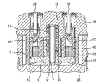
図1には、本発明により形成された電磁弁を備えた燃料インジェクタの第1実施例が部分断面図で示されている。 FIG. 1 is a partial cross-sectional view of a first embodiment of a fuel injector having a solenoid valve formed according to the present invention.
本発明により形成された燃料インジェクタ1では、噴射弁部材(図示せず)を制御する制御ピストン2が、電磁弁3によって制御される。前記噴射弁部材により、少なくとも1つの噴射開口が開閉され、このようにして内燃機関の燃焼室への燃料噴射が制御される。
In the fuel injector 1 formed according to the present invention, a
制御ピストン2の運動は液圧式で行われる。このためには、制御ピストン2の噴射弁部材とは反対の側が、制御室4に開口している。流入絞り5を介して、制御室4は燃料流入部6と接続されている。これにより、システム圧下にある燃料が制御室4に流入することができる。流出絞り7を介して制御室4は放圧可能である。このためには、流出絞り7が戻り部(図1には図示せず)と液圧式に接続されている。制御室4をシステム圧下にある燃料で満たすことができるようにするためには、流出絞り7が電磁弁3により閉鎖可能である。このためには、本発明により形成された電磁弁3では、この電磁弁3の可動子9に形成されたシール面8が弁座10にセットされる。図示の実施例では、シール面8と弁座10とが平座を形成している。但し、軸方向力が閉鎖部材に作用しない、当業者に公知のあらゆる別の弁座も考えられる。
The movement of the
電磁弁3が閉じられた状態で、軸方向に作用する押圧力を吸収するためには、可動子9に孔11が形成されており、この孔11にはプッシュロッド12が収容されている。弁の閉じた状態では軸方向の押圧力が可動子9に作用しないようにするためには、孔11の直径がシール面8の内径にほぼ等しい。プッシュロッド12の別の課題は、孔11を漏れ流に対してシールすることである。この理由から、プッシュロッド12及び孔11は、狭小なガイド遊びで製作されていることが不可欠である。但し、従来技術から公知の燃料インジェクタに比べて、シール面8と孔11との精密な直角の向きを得るために、孔11及びシール面8を可動子9に1回のチャックで製作することは必要とされていない。これにより、可動子9の製作が簡略化される。
In order to absorb the pressing force acting in the axial direction in a state where the
シール面8が弁座10に位置する場合に可動子9の下側の行程ストッパを位置調整するためには、可動子9に弾性的なガイドリップ13が形成されている。可動子9の上側の行程ストッパは、行程ストッパスリーブ15の下端面として構成された環状面14によって形成される。
In order to adjust the position of the lower stroke stopper of the
図示の実施例では、行程ストッパスリーブ15に孔16が形成されており、この孔16にはばね部材17が収容されている。このばね部材17は、有利には圧縮ばねとして構成された渦巻ばねであり、一方の側が可動子9に支持され且つ他方の側がディスク18に支持されている。この場合、このディスク18は孔16の端面19に面して設置されている。ディスク18の軸方向伸長により、前記ばね部材17が可動子9に作用させるばね力が調節され得る。
In the illustrated embodiment, a
更に、電磁弁3は磁石20を有しており、この磁石20は磁石コア21に収容されている。磁石20の電圧供給は、ピン28を介して行われる。
Further, the
可動子9のシール面8の平らな支持部が弁座10に到達するためには、この弁座10と、可動子9が下側の行程ストッパに位置する場合に弾性的なガイドリップ13を支持する支持面22とが、所定の1高さに研削されている。同様に、前記支持面に支持される弾性的なガイドリップ13の支持部と、可動子9のシール面8も、やはり所定の1高さに研削されている。
In order for the flat support portion of the
可動子9の行程は、行程ストッパスリーブ15によって制限される。行程を調節するためには、可動子9及び磁石コア21がスリーブ23によって取り囲まれており、このスリーブ23の軸方向伸長によって行程が規定される。行程調節のためには、行程ストッパスリーブ15が端面24で以てスリーブ23に載置されている。
The stroke of the
流入絞り5、流出絞り7、弁座10及び支持面22は弁部材25に形成されており、この弁部材25はインジェクタケーシング26に収容されている。このインジェクタケーシング26における弁部材25の固定は、弁緊締ねじ27を介して行われる。
The
ピン28を行程ストッパスリーブ15を通してガイドするためには、この行程ストッパスリーブ15において各ピン28毎に1つの孔29が形成されている。孔29のピン28をシールし且つセンタリングするためには、ピン28がそれぞれ下部ディスク30と、上部ディスク31と、これらのディスク間に位置するシールリング32とによって取り囲まれている。
In order to guide the
インジェクタケーシング26における行程ストッパスリーブ15の固定は、図示の実施例では緊締ナット33によって行われる。
The
本発明により形成された電磁弁3は、逆転制御型の燃料インジェクタにおいても、非逆転制御型の燃料インジェクタにおいても使用可能である。
The
噴射過程を開始するためには、非逆転制御型の燃料インジェクタにおいては電磁弁3の磁石20が給電される。この場合、非逆転制御型とは、磁石20が給電された状態で少なくとも1つの噴射開口が開放されており且つ燃料が内燃機関の燃焼室に噴射されることを意味している。磁石20の給電により磁界が形成され、この磁界に基づき、可動子9は磁石20により引き付けられ延いては磁石20に向かって運動する。これにより、可動子9のシール面8は弁座10から持ち上がり、制御室4から流出絞り7を介して戻り部に至る接続部が開放される。この開放された接続部に基づき、燃料は制御室4から流出することができる。このことは制御室4内の圧力低下を招く。この制御室4内の圧力低下に基づき、制御ピストン2に作用する押圧力が減少し、制御ピストン2は制御室4内に突入運動する。この制御ピストン2の運動により、噴射弁部材が弁座から持ち上がるので、少なくとも1つの噴射開口が開放され、噴射過程が始まる。
In order to start the injection process, the
可動子9の行程は、この可動子9が行程ストッパスリーブ15の環状面14にぶつかることに基づき、行程ストッパスリーブ15により制限される。
The stroke of the
可動子9の軸方向ガイドは、この可動子9に設けられた付加部34によって行われ、この付加部34は、行程ストッパスリーブ15の孔16内でガイドされている。但し、燃料インジェクタを好適に製作することができるようにするためには、前記孔16と、可動子9の付加部34とは対で研削されてはいないので、一般に0.02〜0.04ミリメートルの範囲の小さな行程にもかかわらず、可動子9の振動を防止することができない。
The
噴射過程が終了される流出絞り7の閉鎖時に、可動子9のシール面8が弁座10に液密にセットされているということを保証するためには、可動子9にばね弾性的なガイドリップ13が形成されている。このばね弾性的なガイドリップ13により、可動子9は、該可動子にばね部材17のばね力が不均等に作用した場合でも、傾動を防止されている。可動子9が傾動した場合には、ばね弾性的なガイドリップ13が支持面22に当接し、これにより、可動子9の更なる傾動を防ぐ。
In order to ensure that the
噴射過程を終了するためには、磁石20の給電が終了される。ばね部材17により、可動子9は磁石から離反運動されるので、シール面8が弁座10にセットされる。これにより、流出絞り7が閉じられる。燃料流入部6及び流入絞り5を介してシステム圧下にある燃料で満たされる制御室4内には、再びシステム圧が形成される。これにより、制御ピストン2に作用する押圧力が増大する。制御ピストン2は噴射弁部材に向かって運動され、このようにして噴射弁部材を弁座にセットし且つ少なくとも1つの噴射開口を閉鎖する。
In order to end the injection process, the power supply to the
逆転制御型の燃料インジェクタが非逆転制御型の燃料インジェクタと異なる点は、磁石の給電状態では少なくとも1つの噴射開口が閉じられており且つ磁石の非給電状態では少なくとも1つの噴射開口が開放されているという点にある。このためには、制御ピストン2と噴射弁部材とが互いに液圧式で結合されており、これにより、制御ピストン2が噴射弁部材に向かって運動すると、この噴射弁部材は弁座から持ち上げられ且つ少なくとも1つの噴射開口が開放され、磁石が給電された状態では、制御ピストン2が制御室4に向かって運動され、これにより、噴射弁部材が弁座にセットされ且つ少なくとも1つの噴射開口が閉じられる。
The difference between the reverse control type fuel injector and the non-reverse control type fuel injector is that at least one injection opening is closed in the power supply state of the magnet and at least one injection opening is open in the non-power supply state of the magnet. It is in that it is. For this purpose, the
図2には、本発明により形成された電磁弁3の第2実施例が示されている。図2に示した実施例が図1に示した実施例と異なる点は、ばね部材17のばね力を調節するディスク35が、ばね部材17と可動子9との間に収容されているという点にある。つまり、ばね部材17の一方の側はディスク35に支持されており且つ他方の側は孔16の端面19に支持されている。図2に示した実施例に基づき、ディスク35は同時に可動子9をセンタリングするために役立つ。可動子9のセンタリングは、当該可動子9が半径方向にずれ、これにより、流出絞り7が閉鎖された場合に可動子9のシール面8が最早弁座10に配置されていないという状態にならないようにするために必要である。
FIG. 2 shows a second embodiment of the
図3には電磁弁3の第3実施例が示されている。
FIG. 3 shows a third embodiment of the
図3に示した実施例が図1に示した実施例と異なる点は、プッシュロッド12がピン36及びプッシュピン37を有しているという点にある。ピン36は可動子9の孔11内でガイドされている。プッシュロッド12がプッシュピン37及びピン36を有していることにより、可動子9がばね部材17による不均一な力負荷に基づき振動し始めた場合に、可動子9がプッシュロッド12に接して傾く恐れがあるということが防止される。このためには、ピン36及びプッシュピン37は、ピン36がプッシュピン37に対して軸方向から傾動可能であるように構成されている。有利にはこのために、少なくともプッシュピン37のピン36に面した側か、又はピン36のプッシュピン37に面した側のいずれかに、球状に形成された端面が設けられている。この場合、球状に形成されたとは、前記端面が1球区分の形、放物面の形又は双曲面の形で構成されているということを意味している。有利な実施例では、プッシュピン37のピン36に面した端面と、ピン36のプッシュピン37に面した端面の両方が球状に構成されている。
The embodiment shown in FIG. 3 is different from the embodiment shown in FIG. 1 in that the
別の実施例では、ピン36とプッシュピン37との間にボールが収容されている。この場合、このボールはピン36及びプッシュピン37の、球状に成形された、互いに面した端面と同じ役割を果たす。
In another embodiment, a ball is accommodated between the
プッシュピン12の課題は、図1〜図3に示した3つの実施例全てにおいて、軸方向の押圧力を吸収することにある。このためには、当該プッシュピン12は行程ストッパスリーブ15に設けられた孔16の端面19に支持されている。これにより、プッシュピン12に加えられた押圧力が、行程ストッパスリーブ15に伝達される。
The problem of the
ばね部材17若しくはディスク18及びプッシュロッド12が行程ストッパスリーブ15に設けられた孔16の端面19に支持された、図1〜図3に示した実施例の他に、孔16が行程ストッパスリーブを完全に貫通しており且つディスク18若しくはばね部材17及びプッシュロッド12がインジェクタケーシングに直接に支持されていることも可能である。この場合、孔16はインジェクタケーシングによって閉鎖される。
In addition to the embodiment shown in FIGS. 1 to 3, in which the
1 燃料インジェクタ、 2 制御ピストン、 3 電磁弁、 4 制御室、 5 流入絞り、 6 燃料流入部、 7 流出絞り、 8 シール面、 9 可動子、 10 弁座、 11 孔、 12 プッシュロッド、 13 弾性的なガイドリップ、 14 環状面、 15 行程ストッパスリーブ、 16 孔、 17 ばね部材、 18 ディスク、 19 端面、 20 磁石、 21 磁石コア、 22 支持面、 23 スリーブ、 24 端面、 25 弁部材、 26 インジェクタケーシング、 27 弁緊締ねじ、 28 ピン、 29 孔、 30 下部ディスク、 31 上部ディスク、 32 シールリング、 33 緊締ナット、 34 付加部、 35 ディスク、 36 ピン、 37 プッシュピン DESCRIPTION OF SYMBOLS 1 Fuel injector, 2 Control piston, 3 Solenoid valve, 4 Control chamber, 5 Inflow restrictor, 6 Fuel inflow part, 7 Outflow restrictor, 8 Seal surface, 9 Movable element, 10 Valve seat, 11 Hole, 12 Push rod, 13 Elasticity Guide lip, 14 annular surface, 15 stroke stopper sleeve, 16 hole, 17 spring member, 18 disc, 19 end surface, 20 magnet, 21 magnet core, 22 support surface, 23 sleeve, 24 end surface, 25 valve member, 26 injector Casing, 27 Valve tightening screw, 28 pin, 29 holes, 30 Lower disk, 31 Upper disk, 32 Seal ring, 33 Tightening nut, 34 Additional part, 35 Disk, 36 pin, 37 Push pin
Claims (11)
前記電磁弁(3)の可動子(9)に、制御弁を閉じるために弁座(10)にセット可能なシール面(8)が形成されており、前記可動子(9)が、上下の行程ストッパ間を運動することができ、前記シール面(8)とは反対の側の可動子(9)の端部に付加部(34)が設けられており、該付加部(34)が、上側の行程ストッパを形成する行程ストッパスリーブ(15)の孔(16)内でガイドされており、前記可動子(9)に設けられた孔(11)に、軸方向の押圧力を吸収するためのプッシュロッド(12)が収容されており、
該プッシュロッド(12)は行程ストッパスリーブ(15)に設けられた孔(16)の端面(19)に支持されており、これにより、プッシュロッド(12)に加えられた押圧力が、行程ストッパスリーブ(15)に伝達されるようになっていることを特徴とする、内燃機関の燃焼室に燃料を噴射するための燃料インジェクタ。 A fuel injector for injecting fuel into a combustion chamber of an internal combustion engine, wherein an injection valve member for opening and closing at least one injection opening in the fuel injector is formed by a control valve formed as an electromagnetic valve (3) In the controlled form,
A seal surface (8) that can be set on the valve seat (10) to close the control valve is formed on the mover (9) of the electromagnetic valve (3), and the mover (9) An additional portion (34) is provided at the end of the movable element (9) on the side opposite to the sealing surface (8). Guided in the hole (16) of the stroke stopper sleeve (15) that forms the upper stroke stopper, in order to absorb the axial pressing force in the hole (11) provided in the movable element (9). The push rod (12) is housed,
The push rod (12) is supported by an end face (19) of a hole (16) provided in the stroke stopper sleeve (15), whereby the pressing force applied to the push rod (12) is applied to the stroke stopper. A fuel injector for injecting fuel into a combustion chamber of an internal combustion engine, characterized in that it is transmitted to a sleeve (15).
Applications Claiming Priority (2)
| Application Number | Priority Date | Filing Date | Title |
|---|---|---|---|
| DE102006021736A DE102006021736A1 (en) | 2006-05-10 | 2006-05-10 | Fuel injector with pressure compensated control valve |
| DE102006021736.5 | 2006-05-10 |
Related Parent Applications (1)
| Application Number | Title | Priority Date | Filing Date |
|---|---|---|---|
| JP2009508273A Division JP5054762B2 (en) | 2006-05-10 | 2007-03-19 | Fuel injector with pressure compensated control valve |
Publications (2)
| Publication Number | Publication Date |
|---|---|
| JP2012137097A true JP2012137097A (en) | 2012-07-19 |
| JP5783947B2 JP5783947B2 (en) | 2015-09-24 |
Family
ID=38157536
Family Applications (2)
| Application Number | Title | Priority Date | Filing Date |
|---|---|---|---|
| JP2009508273A Active JP5054762B2 (en) | 2006-05-10 | 2007-03-19 | Fuel injector with pressure compensated control valve |
| JP2012093416A Active JP5783947B2 (en) | 2006-05-10 | 2012-04-16 | Fuel injector with pressure compensated control valve |
Family Applications Before (1)
| Application Number | Title | Priority Date | Filing Date |
|---|---|---|---|
| JP2009508273A Active JP5054762B2 (en) | 2006-05-10 | 2007-03-19 | Fuel injector with pressure compensated control valve |
Country Status (8)
| Country | Link |
|---|---|
| US (1) | US8371516B2 (en) |
| EP (1) | EP2021617B1 (en) |
| JP (2) | JP5054762B2 (en) |
| CN (1) | CN101490405B (en) |
| AT (1) | ATE534815T1 (en) |
| DE (1) | DE102006021736A1 (en) |
| RU (1) | RU2451821C2 (en) |
| WO (1) | WO2007128612A1 (en) |
Families Citing this family (25)
| Publication number | Priority date | Publication date | Assignee | Title |
|---|---|---|---|---|
| DE102006053128A1 (en) * | 2006-11-10 | 2008-05-15 | Robert Bosch Gmbh | Injector for injecting fuel |
| DE102007018472A1 (en) * | 2007-04-19 | 2008-10-23 | Robert Bosch Gmbh | Fuel injector with solenoid valve |
| DE102007025961A1 (en) * | 2007-06-04 | 2008-12-11 | Robert Bosch Gmbh | injector |
| DE102007044362A1 (en) * | 2007-09-17 | 2009-03-19 | Robert Bosch Gmbh | Control valve for a fuel injector |
| DE102007044361A1 (en) * | 2007-09-17 | 2009-03-19 | Robert Bosch Gmbh | Control valve for a fuel injector |
| DE102007047425A1 (en) | 2007-10-04 | 2009-04-09 | Robert Bosch Gmbh | Control valve for a fuel injector |
| DE102007052361A1 (en) * | 2007-11-02 | 2009-05-07 | Robert Bosch Gmbh | Elastic seat for switching valves |
| DE102008003348A1 (en) * | 2008-01-07 | 2009-07-09 | Robert Bosch Gmbh | fuel injector |
| DE102008002146A1 (en) | 2008-06-02 | 2009-12-03 | Robert Bosch Gmbh | Fuel injector with seat hole nozzle |
| DE102008040161A1 (en) * | 2008-07-04 | 2010-01-07 | Robert Bosch Gmbh | Solenoid valve for a fuel injector and fuel injector |
| DE102008040637A1 (en) * | 2008-07-23 | 2010-01-28 | Robert Bosch Gmbh | Fuel injection valve device |
| DE102009029116A1 (en) * | 2009-09-02 | 2011-03-03 | Robert Bosch Gmbh | Fuel injector |
| DE102009045335A1 (en) * | 2009-10-05 | 2011-04-07 | Robert Bosch Gmbh | injector |
| DE102009046563A1 (en) * | 2009-11-10 | 2011-05-12 | Robert Bosch Gmbh | fuel injector |
| DE102010001486A1 (en) * | 2010-02-02 | 2011-08-04 | Robert Bosch GmbH, 70469 | Control valve arrangement of a fuel injector |
| JP5637008B2 (en) * | 2011-02-24 | 2014-12-10 | 株式会社デンソー | Injector |
| JP5637009B2 (en) * | 2011-02-24 | 2014-12-10 | 株式会社デンソー | Injector |
| JP2013174158A (en) * | 2012-02-24 | 2013-09-05 | Nabtesco Corp | Solenoid valve |
| DE102012221543A1 (en) * | 2012-11-26 | 2014-05-28 | Robert Bosch Gmbh | valve means |
| DE102014225293A1 (en) | 2014-12-09 | 2016-06-09 | Robert Bosch Gmbh | fuel injector |
| DE102015202726A1 (en) * | 2015-02-16 | 2016-08-18 | Robert Bosch Gmbh | Control valve assembly |
| DE102016225580A1 (en) * | 2016-12-20 | 2018-06-21 | Robert Bosch Gmbh | Device for metering a gaseous fuel to an injector |
| DE102016225946A1 (en) * | 2016-12-22 | 2018-06-28 | Robert Bosch Gmbh | Fuel injector and its use |
| US11466652B2 (en) * | 2017-06-14 | 2022-10-11 | Cummins Inc. | Fuel injector having a self-contained replaceable pilot valve assembly |
| CN109488772B (en) * | 2018-11-30 | 2019-12-03 | 北京理工大学 | A kind of double sealing structure of injection electromagnetic valve |
Citations (2)
| Publication number | Priority date | Publication date | Assignee | Title |
|---|---|---|---|---|
| JPH0979104A (en) * | 1995-09-12 | 1997-03-25 | Nippon Soken Inc | Pressure accumulating type fuel injection device |
| JP2005016528A (en) * | 2004-10-08 | 2005-01-20 | Bosch Automotive Systems Corp | Fuel injection valve |
Family Cites Families (28)
| Publication number | Priority date | Publication date | Assignee | Title |
|---|---|---|---|---|
| ES487024A1 (en) * | 1979-01-25 | 1980-06-16 | Bendix Corp | Fuel injector with electronically operated control. |
| SU909263A1 (en) * | 1980-05-26 | 1982-02-28 | Коломенский Филиал Всесоюзного Заочного Политехнического Института | Injection nozzle |
| US4482094A (en) * | 1983-09-06 | 1984-11-13 | General Motors Corporation | Electromagnetic unit fuel injector |
| JPS6220980A (en) * | 1985-07-18 | 1987-01-29 | Diesel Kiki Co Ltd | Solenoid-controlled valve |
| JPH0338540Y2 (en) | 1987-03-30 | 1991-08-14 | ||
| DE3727342A1 (en) * | 1987-08-17 | 1989-03-02 | Bosch Gmbh Robert | ELECTROMAGNETICALLY ACTUABLE FUEL INJECTION VALVE |
| IT212429Z2 (en) * | 1987-08-25 | 1989-07-04 | Weber Srl | FAST SOLENOID VALVE PARTICULARLY FUEL INJECTION PILOT VALVE FOR DIESEL CYCLE ENGINES |
| DE3802648A1 (en) * | 1988-01-29 | 1989-08-10 | Mainz Gmbh Feinmech Werke | Electromagnetically actuated hydraulic quick-action switching valve |
| SU1719703A1 (en) * | 1989-06-14 | 1992-03-15 | Коломенский Филиал Всесоюзного Заочного Политехнического Института | Electrically controllable pump-injector of diesel |
| DE3936619A1 (en) * | 1989-11-03 | 1991-05-08 | Man Nutzfahrzeuge Ag | METHOD FOR INJECTING A FUEL INTO THE COMBUSTION CHAMBER OF AN AIR COMPRESSING, SELF-IGNITION ENGINE, AND APPARATUS FOR CARRYING OUT THIS METHOD |
| US5381965A (en) * | 1993-02-16 | 1995-01-17 | Siemens Automotive L.P. | Fuel injector |
| CN1057367C (en) * | 1994-02-15 | 2000-10-11 | 英文特工程有限公司 | Hydraulically actuated electronic fuel injection system |
| JPH0861152A (en) * | 1994-08-12 | 1996-03-05 | Honda Motor Co Ltd | Fuel injection device |
| US5947380A (en) * | 1997-11-03 | 1999-09-07 | Caterpillar Inc. | Fuel injector utilizing flat-seat poppet valves |
| DE19833461A1 (en) * | 1998-07-24 | 2000-01-27 | Bosch Gmbh Robert | Electromagnetically operated valve for fuel injection compressed mixtures and external fuel ignition has specially designed impact area acting as core or relay armature |
| RU2150019C1 (en) * | 1999-03-16 | 2000-05-27 | Пинский Феликс Ильич | Electrohydraulic injector |
| DE10039039A1 (en) * | 2000-08-10 | 2002-02-21 | Bosch Gmbh Robert | Solenoid valve for controlling an injection valve for internal combustion engines and electromagnet therefor |
| CN1133808C (en) * | 2000-10-20 | 2004-01-07 | 昆腾燃料系统技术环球公司 | Gas fuel injector |
| DE10124747A1 (en) * | 2001-05-21 | 2002-11-28 | Bosch Gmbh Robert | Fuel injection valve for internal combustion engines comprises an armature buffer surface and/or a counter-buffer surface having in a recess an elastic damping element protruding over the armature buffer surface/ counter-buffer surface |
| DE10131199A1 (en) | 2001-06-28 | 2003-01-16 | Bosch Gmbh Robert | Solenoid valve for controlling an injection valve of an internal combustion engine |
| DE10161002A1 (en) * | 2001-12-12 | 2003-07-03 | Bosch Gmbh Robert | Solenoid valve for controlling an injection valve of an internal combustion engine |
| JP3757261B2 (en) * | 2002-08-05 | 2006-03-22 | ボッシュ株式会社 | Fuel injection valve |
| RU2247855C1 (en) * | 2003-07-21 | 2005-03-10 | Открытое акционерное общество "Ярославский завод топливной аппаратуры" (ОАО "ЯЗТА") | Nozzle for internal combustion engine |
| DE102004010759A1 (en) * | 2004-03-05 | 2005-09-22 | Robert Bosch Gmbh | Common rail injector |
| DE602004002686T8 (en) * | 2004-06-30 | 2008-01-03 | C.R.F. Società Consortile per Azioni, Orbassano | Fuel injector with force balanced control valve |
| DE602004004254T2 (en) * | 2004-06-30 | 2007-07-12 | C.R.F. S.C.P.A. | Servo valve for controlling an injection valve of an internal combustion engine |
| ATE468482T1 (en) * | 2005-03-14 | 2010-06-15 | Fiat Ricerche | ADJUSTABLE DOSING SERVO VALVE OF AN INJECTION VALVE AND ITS ADJUSTMENT METHOD |
| EP1707797B1 (en) * | 2005-03-14 | 2007-08-22 | C.R.F. Società Consortile per Azioni | Adjustable metering servovalve for a fuel injector |
-
2006
- 2006-05-10 DE DE102006021736A patent/DE102006021736A1/en not_active Withdrawn
-
2007
- 2007-03-19 US US12/300,016 patent/US8371516B2/en active Active
- 2007-03-19 CN CN2007800264915A patent/CN101490405B/en active Active
- 2007-03-19 JP JP2009508273A patent/JP5054762B2/en active Active
- 2007-03-19 AT AT07727028T patent/ATE534815T1/en active
- 2007-03-19 EP EP07727028A patent/EP2021617B1/en active Active
- 2007-03-19 RU RU2008148287/06A patent/RU2451821C2/en active
- 2007-03-19 WO PCT/EP2007/052550 patent/WO2007128612A1/en active Application Filing
-
2012
- 2012-04-16 JP JP2012093416A patent/JP5783947B2/en active Active
Patent Citations (2)
| Publication number | Priority date | Publication date | Assignee | Title |
|---|---|---|---|---|
| JPH0979104A (en) * | 1995-09-12 | 1997-03-25 | Nippon Soken Inc | Pressure accumulating type fuel injection device |
| JP2005016528A (en) * | 2004-10-08 | 2005-01-20 | Bosch Automotive Systems Corp | Fuel injection valve |
Also Published As
| Publication number | Publication date |
|---|---|
| EP2021617B1 (en) | 2011-11-23 |
| WO2007128612A1 (en) | 2007-11-15 |
| DE102006021736A1 (en) | 2007-11-15 |
| CN101490405A (en) | 2009-07-22 |
| RU2451821C2 (en) | 2012-05-27 |
| US20090159727A1 (en) | 2009-06-25 |
| RU2008148287A (en) | 2010-06-20 |
| US8371516B2 (en) | 2013-02-12 |
| JP5783947B2 (en) | 2015-09-24 |
| ATE534815T1 (en) | 2011-12-15 |
| JP2009536288A (en) | 2009-10-08 |
| JP5054762B2 (en) | 2012-10-24 |
| EP2021617A1 (en) | 2009-02-11 |
| CN101490405B (en) | 2012-04-18 |
Similar Documents
| Publication | Publication Date | Title |
|---|---|---|
| JP5783947B2 (en) | Fuel injector with pressure compensated control valve | |
| RU2441171C2 (en) | Fuel injector with equalised-pressure control valve | |
| US7458529B2 (en) | Adjustable metering servovalve for a fuel injector | |
| US9546630B2 (en) | Injection valve | |
| KR100558588B1 (en) | Magnetic valve | |
| US5820101A (en) | Electromagnetic metering valve for a fuel injector | |
| US5842640A (en) | Fuel injection valve for internal combustion engines | |
| US7284712B2 (en) | Injector having structure for controlling nozzle needle | |
| CN101535625B (en) | Injector for injecting fuel | |
| US7055766B2 (en) | Internal combustion engine fuel injector | |
| JP2004521269A (en) | Solenoid valve with plug-in rotary connection | |
| US6745993B2 (en) | Fuel injection valve | |
| JPH05133296A (en) | Electromagnetic type internal combustion engine fuel injector | |
| JP2004515689A (en) | Fuel injection device for internal combustion engine | |
| JP4495761B2 (en) | Magnet valve operated fuel injector with hydraulic excess stroke stopper | |
| JP5355791B2 (en) | Valve device | |
| WO2018115197A1 (en) | Valve assembly for an injection valve and injection valve | |
| JP3757261B2 (en) | Fuel injection valve | |
| JP2018528349A (en) | Valve for metering fluid | |
| JP2005505720A (en) | Fuel injector with compensation element for use in a fuel injection system | |
| CN108291509A (en) | Fuel injector with control valve | |
| US20090212136A1 (en) | Solenoid valve and fuel injector having the same | |
| JP2004518871A (en) | Injection nozzle | |
| US20230022358A1 (en) | Fuel injector for injecting fuel | |
| JP3796735B2 (en) | Fuel injection valve |
Legal Events
| Date | Code | Title | Description |
|---|---|---|---|
| A621 | Written request for application examination |
Free format text: JAPANESE INTERMEDIATE CODE: A621 Effective date: 20120516 |
|
| A977 | Report on retrieval |
Free format text: JAPANESE INTERMEDIATE CODE: A971007 Effective date: 20130628 |
|
| A131 | Notification of reasons for refusal |
Free format text: JAPANESE INTERMEDIATE CODE: A131 Effective date: 20130729 |
|
| A601 | Written request for extension of time |
Free format text: JAPANESE INTERMEDIATE CODE: A601 Effective date: 20131029 |
|
| A602 | Written permission of extension of time |
Free format text: JAPANESE INTERMEDIATE CODE: A602 Effective date: 20131101 |
|
| A521 | Request for written amendment filed |
Free format text: JAPANESE INTERMEDIATE CODE: A523 Effective date: 20140121 |
|
| A131 | Notification of reasons for refusal |
Free format text: JAPANESE INTERMEDIATE CODE: A131 Effective date: 20140707 |
|
| A601 | Written request for extension of time |
Free format text: JAPANESE INTERMEDIATE CODE: A601 Effective date: 20141007 |
|
| A602 | Written permission of extension of time |
Free format text: JAPANESE INTERMEDIATE CODE: A602 Effective date: 20141010 |
|
| A521 | Request for written amendment filed |
Free format text: JAPANESE INTERMEDIATE CODE: A523 Effective date: 20141209 |
|
| TRDD | Decision of grant or rejection written | ||
| A01 | Written decision to grant a patent or to grant a registration (utility model) |
Free format text: JAPANESE INTERMEDIATE CODE: A01 Effective date: 20150622 |
|
| A61 | First payment of annual fees (during grant procedure) |
Free format text: JAPANESE INTERMEDIATE CODE: A61 Effective date: 20150721 |
|
| R150 | Certificate of patent or registration of utility model |
Ref document number: 5783947 Country of ref document: JP Free format text: JAPANESE INTERMEDIATE CODE: R150 |
|
| R250 | Receipt of annual fees |
Free format text: JAPANESE INTERMEDIATE CODE: R250 |
|
| R250 | Receipt of annual fees |
Free format text: JAPANESE INTERMEDIATE CODE: R250 |
|
| R250 | Receipt of annual fees |
Free format text: JAPANESE INTERMEDIATE CODE: R250 |
|
| R250 | Receipt of annual fees |
Free format text: JAPANESE INTERMEDIATE CODE: R250 |
|
| R250 | Receipt of annual fees |
Free format text: JAPANESE INTERMEDIATE CODE: R250 |
|
| R250 | Receipt of annual fees |
Free format text: JAPANESE INTERMEDIATE CODE: R250 |