JP2012132559A - High operation angle type tripod constant velocity joint - Google Patents
High operation angle type tripod constant velocity joint Download PDFInfo
- Publication number
- JP2012132559A JP2012132559A JP2011264069A JP2011264069A JP2012132559A JP 2012132559 A JP2012132559 A JP 2012132559A JP 2011264069 A JP2011264069 A JP 2011264069A JP 2011264069 A JP2011264069 A JP 2011264069A JP 2012132559 A JP2012132559 A JP 2012132559A
- Authority
- JP
- Japan
- Prior art keywords
- roller
- constant velocity
- peripheral surface
- velocity joint
- shaft
- Prior art date
- Legal status (The legal status is an assumption and is not a legal conclusion. Google has not performed a legal analysis and makes no representation as to the accuracy of the status listed.)
- Pending
Links
Images


Classifications
-
- F—MECHANICAL ENGINEERING; LIGHTING; HEATING; WEAPONS; BLASTING
- F16—ENGINEERING ELEMENTS AND UNITS; GENERAL MEASURES FOR PRODUCING AND MAINTAINING EFFECTIVE FUNCTIONING OF MACHINES OR INSTALLATIONS; THERMAL INSULATION IN GENERAL
- F16D—COUPLINGS FOR TRANSMITTING ROTATION; CLUTCHES; BRAKES
- F16D3/00—Yielding couplings, i.e. with means permitting movement between the connected parts during the drive
- F16D3/16—Universal joints in which flexibility is produced by means of pivots or sliding or rolling connecting parts
- F16D3/20—Universal joints in which flexibility is produced by means of pivots or sliding or rolling connecting parts one coupling part entering a sleeve of the other coupling part and connected thereto by sliding or rolling members
- F16D3/202—Universal joints in which flexibility is produced by means of pivots or sliding or rolling connecting parts one coupling part entering a sleeve of the other coupling part and connected thereto by sliding or rolling members one coupling part having radially projecting pins, e.g. tripod joints
- F16D3/205—Universal joints in which flexibility is produced by means of pivots or sliding or rolling connecting parts one coupling part entering a sleeve of the other coupling part and connected thereto by sliding or rolling members one coupling part having radially projecting pins, e.g. tripod joints the pins extending radially outwardly from the coupling part
- F16D3/2055—Universal joints in which flexibility is produced by means of pivots or sliding or rolling connecting parts one coupling part entering a sleeve of the other coupling part and connected thereto by sliding or rolling members one coupling part having radially projecting pins, e.g. tripod joints the pins extending radially outwardly from the coupling part having three pins, i.e. true tripod joints
-
- F—MECHANICAL ENGINEERING; LIGHTING; HEATING; WEAPONS; BLASTING
- F16—ENGINEERING ELEMENTS AND UNITS; GENERAL MEASURES FOR PRODUCING AND MAINTAINING EFFECTIVE FUNCTIONING OF MACHINES OR INSTALLATIONS; THERMAL INSULATION IN GENERAL
- F16D—COUPLINGS FOR TRANSMITTING ROTATION; CLUTCHES; BRAKES
- F16D3/00—Yielding couplings, i.e. with means permitting movement between the connected parts during the drive
- F16D3/16—Universal joints in which flexibility is produced by means of pivots or sliding or rolling connecting parts
- F16D3/20—Universal joints in which flexibility is produced by means of pivots or sliding or rolling connecting parts one coupling part entering a sleeve of the other coupling part and connected thereto by sliding or rolling members
- F16D3/202—Universal joints in which flexibility is produced by means of pivots or sliding or rolling connecting parts one coupling part entering a sleeve of the other coupling part and connected thereto by sliding or rolling members one coupling part having radially projecting pins, e.g. tripod joints
- F16D2003/2026—Universal joints in which flexibility is produced by means of pivots or sliding or rolling connecting parts one coupling part entering a sleeve of the other coupling part and connected thereto by sliding or rolling members one coupling part having radially projecting pins, e.g. tripod joints with trunnion rings, i.e. with tripod joints having rollers supported by a ring on the trunnion
Landscapes
- Engineering & Computer Science (AREA)
- General Engineering & Computer Science (AREA)
- Mechanical Engineering (AREA)
- Friction Gearing (AREA)
- Rolling Contact Bearings (AREA)
- General Details Of Gearings (AREA)
Abstract
Description
本発明は、高切れ角型トライポッド等速ジョイントに関し、より詳しくは、インナーローラーの上端部の外周面に突起部を形成して、アウターローラーの離脱を防止しかつインナーローラーの上下の流動幅を最大化することによって、最大切れ角量を向上させることができ、アウターローラーの幅を相対的に小さく設定でき、部品数を減らして製作費用を節減することができる、高切れ角型トライポッド等速ジョイントに関する。 More specifically, the present invention relates to a constant angle tripod constant velocity joint, and more specifically, a protrusion is formed on the outer peripheral surface of the upper end portion of the inner roller to prevent the outer roller from being separated and to increase the vertical flow width of the inner roller. By maximizing, the maximum cutting angle amount can be improved, the width of the outer roller can be set relatively small, the number of parts can be reduced and the manufacturing cost can be reduced, the high cutting angle type tripod constant speed Regarding joints.
一般に、ジョイントは回転軸の角度が互いに異なる回転軸に回転動力(トルク)を伝達するためのものであって、動力伝達角度が小さい推進軸の場合にはフックジョイント、フレキシブルジョイントなどが用いられ、動力伝達角度が大きい前輪駆動車の駆動軸の場合には等速ジョイントが用いられる。 In general, the joint is for transmitting rotational power (torque) to rotational shafts having different rotational shaft angles, and in the case of a propulsion shaft having a small power transmission angle, a hook joint, a flexible joint, etc. are used. In the case of a drive shaft of a front wheel drive vehicle having a large power transmission angle, a constant velocity joint is used.
前記等速ジョイントは駆動軸と受動軸との交差角が大きい場合においても等速で円滑に動力を伝達できるので独立懸架方式の前輪駆動車のアクスル軸に主に用いられ、シャフトを中心としてエンジン側はトライポッド式等速ジョイントからなり、シャフトを中心としてタイヤ側はバフィールド式等速ジョイントからなる。 The constant velocity joint is used mainly for the axle shaft of an independent suspension type front-wheel drive vehicle because the power can be transmitted smoothly at a constant speed even when the intersection angle between the drive shaft and the passive shaft is large. The side consists of a tripod constant velocity joint, and the tire side around the shaft consists of a Bufffield constant velocity joint.
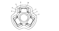
図1は一般的な等速ジョイントの断面構成図であり、図2は図1のA-A線断面図である。 FIG. 1 is a sectional configuration diagram of a general constant velocity joint, and FIG. 2 is a sectional view taken along line AA in FIG.
図1および図2に示されているように、一般的な等速ジョイントの構成は、シャフト1を中心としてエンジン側(インボード側)はトライポッド式等速ジョイントからなり、シャフト1を中心として車輪側(アウトボード側)はバフィールド式等速ジョイントからなる。
As shown in FIG. 1 and FIG. 2, a general constant velocity joint is configured by a tripod type constant velocity joint on the engine side (inboard side) around the
シャフト1を中心としてエンジン側(インボード側)に設けられている前記トライポッド式等速ジョイントの構成は、エンジン(図示省略)の回転動力を伝達し、内部にトラック溝が形成されているハウジング2と、前記ハウジング2の回転動力が伝達されて回転するシャフト1と、前記ハウジング2とシャフト1とを連結するために前記シャフト1の一端に連結されて前記ハウジング2の内部に設けられ、三つのトラニオン3aが形成されて前記トラック溝に挿入されるスパイダー3と、前記スパイダー3のトラニオン3aの外周面に設けられるインナーローラー6と、前記インナーローラー6の外周面に設けられるニードルローラ5と、前記ニードルローラ5の外周面に設けられて前記ハウジング2とシャフト1との摩擦を減少させるアウターローラー4と、前記アウターローラー4の離脱を防止するためにアウターローラー4の下部に組立てられるリテーナクリップ8と、前記ハウジング2に一端が連結され、前記シャフト1に一端が連結されるブーツ10と、前記ブーツ10をそれぞれ固定させるためのクランピングバンド11、12を含んでなる。
The structure of the tripod type constant velocity joint provided on the engine side (inboard side) with the
シャフト1を中心としてタイヤ側(アウトボード側)に設けられている前記バフィールド式等速ジョイントの構成は、前記トライポッド式等速ジョイントの回転動力が伝達されて回転するシャフト1の一端に連結、設けられるインナーレース15と、前記インナーレース15の外部に設けられるアウターレース13と、前記インナーレース15の回転動力を前記アウターレース13に伝達するためのボール16と、前記ボール16を保持するためのケージ14と、前記アウターレース13の外部に設けられるセンサーリング17と、前記シャフト1に一端が連結され、前記アウターレース13に一端が連結されるブーツ18と、前記ブーツ18を固定させるためのクランピングバンド19、20を含んでなる。
The structure of the Bufffield type constant velocity joint provided on the tire side (outboard side) with the
以下、前記構成による一般的な等速ジョイントの作用について説明する。
エンジン(図示省略)から出力された回転動力がトランスミッション(図示省略)を経由してハウジング2に伝達されるとハウジング2が回転し、このようなハウジング2の回転動力はアウターローラー4、ニードルローラ5、インナーローラー6を通じてスパイダー3に伝達されることによって、スパイダー3に連結されているシャフト1を回転させる。また、前記シャフト1の回転動力はインナーレース15とボール16とを経由してアウターレース13に伝達されることによって、アウターレース13に連結される車輪(図示省略)を回転させることになる。
Hereinafter, the operation of a general constant velocity joint having the above-described configuration will be described.
When the rotational power output from the engine (not shown) is transmitted to the
この場合、シャフト1を中心としてエンジン側(インボード側)に設けられているトライポッド式等速ジョイントではアウターローラー4がハウジング2のトラック溝内をスライディング移動することによって、アウターローラー4と関連しているシャフト1の回転角度が異なることになるので車両の変位によって切れ角になり、シャフト1を中心として車輪側(アウトボード側)に設けられているバフィールド式等速ジョイントではボール16によってアウターレース13の回転角度が異なることになり、車両の変位によって切れ角になる。
In this case, in the tripod type constant velocity joint provided on the engine side (inboard side) with the
そして、トライポッド式等速ジョイント側のブーツ10およびバフィールド式等速ジョイント側のブーツ18は、それぞれトライポッド式等速ジョイントおよびバフィールド式等速ジョイントの外部を取り囲んで密封させることによって、トライポッド式等速ジョイントおよびバフィールド式等速ジョイントが外部汚染物質によって損傷するのを防止する。
Then, the tripod type constant velocity
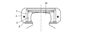
一方、前記トライポッド式等速ジョイントにおいては、図3に示されているようにリテーナクリップ8を用いて、スパイダー3からアウターローラー4が離脱することを防止できる。
On the other hand, in the tripod type constant velocity joint, it is possible to prevent the
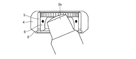
このような構造によってトライポッド式等速ジョイントが切れ角になると、図4に示されているように、インナーローラー6が下方に下降しながら特定角度以上でインナーローラー6とリテーナクリップ8との間で干渉が発生するようになるが、トライポッド式等速ジョイントの切れ角時に前記インナーローラー6がリテーナクリップ8との干渉が発生する前までに下方に下降できる距離は、最大切れ角量を決める重要な要素になる。
When the tripod type constant velocity joint has a cutting angle by such a structure, as shown in FIG. 4, the
しかしながら、前記従来のトライポッド式等速ジョイントは、インナーローラー6とリテーナクリップと8の干渉現象によって最大切れ角量を増やすのに限界があるという問題点がある。
However, the conventional tripod type constant velocity joint has a problem in that there is a limit in increasing the maximum cutting angle due to the interference phenomenon between the
また、前記従来のトライポッド式等速ジョイントは、アウターローラー4にリテーナクリップ8を設置しなければならないので、アウターローラー4の幅が相対的に大きくなるという問題点がある。
Further, the conventional tripod type constant velocity joint has a problem that the width of the
本発明の目的は、前記のような従来の問題点を解決するためのものであって、インナーローラーの上端部の外周面に突起部を形成してアウターローラーの離脱を防止しかつインナーローラーの上下の流動幅を最大化させることによって最大切れ角量を向上させることができ、アウターローラーの幅を相対的に小さく設定できる、高切れ角型トライポッド等速ジョイントを提供することにある。 An object of the present invention is to solve the conventional problems as described above, and a protrusion is formed on the outer peripheral surface of the upper end portion of the inner roller to prevent the outer roller from being detached and the inner roller. It is an object of the present invention to provide a high-cut corner type tripod constant velocity joint in which the maximum cutting angle can be improved by maximizing the upper and lower flow widths and the width of the outer roller can be set relatively small.
また、本発明の目的は、リテーナクリップを使用せず、アウターローラーの離脱を防止することができるので、部品数を減らして製作費用を節減することができる高切れ角型トライポッド等速ジョイントを提供することにある。 In addition, the object of the present invention is to provide a constant angle tripod constant velocity joint that can reduce the number of parts and reduce the manufacturing cost because it can prevent the outer roller from detaching without using a retainer clip. There is to do.
前記目的を達成するための手段として本発明の構成は、エンジンの回転動力を伝達し、内部にトラック溝が形成されているハウジングと、前記ハウジングの回転動力が伝達されて回転するシャフトと、前記ハウジングとシャフトとを連結するために前記シャフトの一端に連結されて前記ハウジングの内部に設けられ、三つのトラニオンが形成されて前記トラック溝に挿入されるスパイダーと、前記スパイダーのトラニオンの外周面に設けられ、上端部の外周面に突起部が突出形成されているインナーローラーと、前記インナーローラーの外周面に設けられるニードルローラと、上端部の内周面および下端部の内周面に内側の最小径を有する突起部がそれぞれ突出形成されており、前記ニードルローラの外周面に設けられ、前記ハウジングとシャフトとの摩擦を減少させるアウターローラーとを含んでなる。 As a means for achieving the above object, the configuration of the present invention includes a housing that transmits rotational power of an engine and has a track groove formed therein, a shaft that rotates by transmitting rotational power of the housing, and A spider connected to one end of the shaft to connect the housing and the shaft, provided inside the housing, formed with three trunnions and inserted into the track groove, and an outer circumferential surface of the trunnion of the spider Provided on the outer peripheral surface of the upper end portion, and a needle roller provided on the outer peripheral surface of the inner roller, and an inner peripheral surface of the upper end portion and an inner peripheral surface of the lower end portion. Protrusions having a minimum diameter are formed so as to protrude from each other and are provided on the outer peripheral surface of the needle roller. Comprising an outer roller to reduce friction between the shift.
本発明の構成は、前記ニードルローラの外側径は前記アウターローラーの内側の最小径より大きいので、前記アウターローラーの上下方向運動いずれもを拘束した方が望ましい。 In the configuration of the present invention, since the outer diameter of the needle roller is larger than the minimum inner diameter of the outer roller, it is desirable to restrain both the vertical movements of the outer roller.
本発明の構成は、前記ニードルローラの内側径は前記インナーローラーの突起部の最大径より小さいので、前記インナーローラーの下方向運動を拘束した方が望ましい。 In the configuration of the present invention, since the inner diameter of the needle roller is smaller than the maximum diameter of the protrusion of the inner roller, it is desirable to restrain the downward movement of the inner roller.
本発明の構成は、前記インナーローラーの上端部の外周面に形成された突起部の最大径は前記ニードルローラの内側径よりは大きく、前記アウターローラーの内側の最小径より小さく形成した方が望ましい。 In the configuration of the present invention, it is preferable that the maximum diameter of the protrusion formed on the outer peripheral surface of the upper end portion of the inner roller is larger than the inner diameter of the needle roller and smaller than the minimum diameter inside the outer roller. .
本発明の構成は、前記アウターローラーが上方に上昇する場合、インナーローラーの上端部の外周面に形成されている突起部によってニードルローラを拘束し、前記ニードルローラによってアウターローラーを拘束した方が望ましい。 In the configuration of the present invention, when the outer roller rises upward, it is preferable that the needle roller is restrained by a protrusion formed on the outer peripheral surface of the upper end portion of the inner roller, and the outer roller is restrained by the needle roller. .
本発明の構成は、前記インナーローラーが下方に下降する場合、ニードルローラによってインナーローラーの上端部の外周面に形成されている突起部を拘束した方が望ましい。 In the configuration of the present invention, it is desirable that when the inner roller descends downward, the protrusion formed on the outer peripheral surface of the upper end portion of the inner roller is restrained by the needle roller.
本発明の構成は、前記トライポッド等速ジョイントをシャフトを中心としてエンジン側(インボード側)に設けた方が望ましい。 In the configuration of the present invention, it is desirable to provide the tripod constant velocity joint on the engine side (inboard side) with the shaft as the center.
本発明は、インナーローラーの上端部の外周面に突起部を形成してアウターローラーの離脱を防止しかつインナーローラーの上下の流動幅を最大化することによって最大切れ角量を向上させることができ、アウターローラーの幅を相対的に小さく設定することができ、部品数を減らして製作費用を節減できるという効果を有する。 The present invention can improve the maximum cutting angle by forming protrusions on the outer peripheral surface of the upper end of the inner roller to prevent the outer roller from detaching and maximizing the upper and lower flow width of the inner roller. The width of the outer roller can be set relatively small, and the production cost can be reduced by reducing the number of parts.
以下、本発明の属する技術分野で通常の知識を有する者が本発明を容易に実施可能であるように詳しく説明するために、本発明の望ましい実施例を添付図面を参照して説明する。本発明の目的、作用および効果を含んだその他の目的、特徴点並びに動作上の利点などが望ましい実施例の説明によってより明確になるだろう。 Hereinafter, preferred embodiments of the present invention will be described in detail with reference to the accompanying drawings so that those skilled in the art to which the present invention pertains can easily carry out the present invention. Other objects, features and operational advantages including the objects, functions and effects of the present invention will become more apparent from the description of the preferred embodiments.
また、本発明における実施例は様々の実施可能な例中において当業者の理解のために望ましい実施例を選択して提示しているものであって、本発明の技術的な思想が必ずそれらに限定されるものではなく、本発明の技術的な思想を外れない範囲内で多様な変化、付加および変更が可能であるのはもちろんであり、均等な他の実施例も実施可能である。 Further, the embodiments of the present invention are presented by selecting preferred embodiments for understanding by those skilled in the art from various possible embodiments, and the technical idea of the present invention is always included in them. The present invention is not limited, and various changes, additions and modifications can be made without departing from the technical idea of the present invention, and other equivalent embodiments can be implemented.
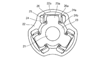
図5は、本発明の一実施例に従う高切れ角型トライポッド等速ジョイントの断面構成図である。 FIG. 5 is a cross-sectional configuration diagram of a high-cut square tripod constant velocity joint according to an embodiment of the present invention.
図5に示されているように、本発明の一実施例に従う高切れ角型トライポッド等速ジョイントの構成は、エンジン(図示省略)の回転動力を伝達し、内部にトラック溝22aが形成されているハウジング22と、前記ハウジング22の回転動力が伝達されて回転するシャフト21と、前記ハウジング22とシャフト21とを連結するために前記シャフト21の一端に連結されて前記ハウジング22の内部に設けられ、三つのトラニオン23aが形成されて前記トラック溝22aに挿入されるスパイダー23と、前記スパイダー23のトラニオン23aの外周面に設けられ、上端部の外周面に突起部26aが突出形成されているインナーローラー26と、前記インナーローラー26の外周面に設けられるニードルローラ25と、前記ニードルローラ25の外周面に設けられて前記ハウジング22とシャフト21との摩擦を減少させるアウターローラー24とを含んでなる。
As shown in FIG. 5, the configuration of the high-cut angle tripod constant velocity joint according to an embodiment of the present invention transmits the rotational power of the engine (not shown), and has a
前記アウターローラー24は、上端部の内周面および下端部の内周面に内側の最小径を有する突起部24a、24bがそれぞれ突出形成されている構造からなる。
The
前記ニードルローラ25の外側径は前記アウターローラー24の内側の最小径より大きいので、前記アウターローラー24の上下方向運動いずれもを拘束する形態で組み立て設けられる。
Since the outside diameter of the
前記ニードルローラ25の内側径は前記インナーローラー26の突起部26aの最大径より小さいので、前記インナーローラー26の下方向運動を拘束する形態で組み立て設けられる。
Since the inner diameter of the
前記インナーローラー26の上端部の外周面に形成された突起部26aの最大径は前記ニードルローラ25の内側径よりは大きく、前記アウターローラー24の内側の最小径よりは小さく形成される構造からなる。
The maximum diameter of the
前記アウターローラー24が上方に上昇する場合、インナーローラー26の上端部の外周面に形成されている突起部26aによってニードルローラ25が拘束され、前記ニードルローラ25によってアウターローラー24が拘束される構造からなる。
When the
前記インナーローラー26が下方に下降する場合、ニードルローラ25によってインナーローラー26の上端部の外周面に形成されている突起部26aが拘束される構造からなる。
When the
以下、前記構成による本発明の一実施例に従う高切れ角型トライポッド等速ジョイントの作用について説明する。 Hereinafter, an operation of the constant angle tripod constant velocity joint according to the embodiment of the present invention having the above-described configuration will be described.
エンジン(図示省略)から出力された回転動力がトランスミッション(図示省略)を経由してハウジング22に伝達されるとハウジング22が回転し、このようなハウジング22の回転動力はアウターローラー24、ニードルローラ25およびインナーローラー26を通じてスパイダー23に伝達されることによって、スパイダー23に連結されているシャフト21を回転させることになる。
When the rotational power output from the engine (not shown) is transmitted to the
シャフト21に回転動力が伝達される過程において、スパイダー23のトラニオン23aに組み立てられているアウターローラー24がハウジング22のトラック溝22a内をスライディング移動することによって、アウターローラー24と関連しているシャフト21の回転角度が異なることになるので、車両の変位によって切れ角になる。
In the process in which the rotational power is transmitted to the
この場合、図6に示されているように、アウターローラー24が矢印方向に沿って上方に上昇すると、インナーローラー26の上端部の外周面に形成されている突起部26aによってニードルローラ25が拘束され、前記ニードルローラ25はアウターローラー24を拘束することによってアウターローラー24が離脱するのを防止できる。
In this case, as shown in FIG. 6, when the
また、図7に示されているように、トライポッド式等速ジョイントが切れ角状態で回転する場合、インナーローラー26が矢印方向に沿って下方に下降すると、インナーローラー26の上端部の外周面に形成されている突起部26aによってニードルローラ25と干渉される時まで下方に下降できるようになるので、相対的にさらに下方に下降できることになる。
Further, as shown in FIG. 7, when the tripod constant velocity joint rotates at a cutting angle, when the
このように、インナーローラー26の上端部の外周面に形成されている突起部26aを利用して、アウターローラー24の離脱を防止するため、アウターローラー24にリテーナクリップ8を設置しなくてもよいので、アウターローラー24の幅を小さく設定できる。
In this manner, the
また、インナーローラー26の上下の流動幅を最大化することによって、等速ジョイントの最大切れ角量を向上させることができる。
Further, by maximizing the upper and lower flow widths of the
21 シャフト
22 ハウジング
23 スパイダー
24 アウターローラー
25 ニードルローラ
26 インナーローラー
21
Claims (7)
前記ハウジングの回転動力が伝達されて回転するシャフトと、
前記ハウジングとシャフトとを連結するために前記シャフトの一端に連結されて前記ハウジングの内部に設けられ、三つのトラニオンが形成されて前記トラック溝に挿入されるスパイダーと、
前記スパイダーのトラニオンの外周面に設けられ、上端部の外周面に突起部が突出形成されているインナーローラーと、
前記インナーローラーの外周面に設けられるニードルローラと、
上端部の内周面および下端部の内周面に内側の最小径を有する突起部がそれぞれ突出形成されており、前記ニードルローラの外周面に設けられて前記ハウジングとシャフトとの摩擦を減少させるアウターローラーと
を含んでなることを特徴とする高切れ角型トライポッド等速ジョイント。 A housing that transmits the rotational power of the engine and in which a track groove is formed;
A shaft that rotates when the rotational power of the housing is transmitted;
A spider connected to one end of the shaft to connect the housing and the shaft, provided inside the housing, and formed with three trunnions inserted into the track groove;
An inner roller that is provided on the outer peripheral surface of the trunnion of the spider and has a protruding portion formed on the outer peripheral surface of the upper end;
A needle roller provided on the outer peripheral surface of the inner roller;
Protrusions having an inner minimum diameter project from the inner peripheral surface of the upper end and the inner peripheral surface of the lower end, and are provided on the outer peripheral surface of the needle roller to reduce friction between the housing and the shaft. A high-cut square tripod constant velocity joint characterized by comprising an outer roller.
Applications Claiming Priority (2)
| Application Number | Priority Date | Filing Date | Title |
|---|---|---|---|
| KR10-2010-0131104 | 2010-12-21 | ||
| KR1020100131104A KR20120069802A (en) | 2010-12-21 | 2010-12-21 | Tripod type constant velocity joint |
Publications (1)
| Publication Number | Publication Date |
|---|---|
| JP2012132559A true JP2012132559A (en) | 2012-07-12 |
Family
ID=45318938
Family Applications (1)
| Application Number | Title | Priority Date | Filing Date |
|---|---|---|---|
| JP2011264069A Pending JP2012132559A (en) | 2010-12-21 | 2011-12-01 | High operation angle type tripod constant velocity joint |
Country Status (5)
| Country | Link |
|---|---|
| US (1) | US20120157215A1 (en) |
| EP (1) | EP2469112A3 (en) |
| JP (1) | JP2012132559A (en) |
| KR (1) | KR20120069802A (en) |
| CN (1) | CN102537101A (en) |
Families Citing this family (3)
| Publication number | Priority date | Publication date | Assignee | Title |
|---|---|---|---|---|
| CN104565097A (en) * | 2014-12-31 | 2015-04-29 | 浙江向隆机械有限公司 | Inner ball cage of constant speed driving shaft |
| CN107091279B (en) * | 2017-05-09 | 2023-08-29 | 青岛科技大学 | Internal three-fork type constant-angular-speed universal coupling |
| CN110259840A (en) * | 2019-06-13 | 2019-09-20 | 奇瑞汽车股份有限公司 | Internal spherical cage assembling structure |
Citations (4)
| Publication number | Priority date | Publication date | Assignee | Title |
|---|---|---|---|---|
| JPH11336783A (en) * | 1998-05-22 | 1999-12-07 | Toyota Motor Corp | Universal uniform coupling |
| JP2005256938A (en) * | 2004-03-11 | 2005-09-22 | Ntn Corp | Joint assembly with unit cover, and bearing device total assembly for driving wheel with the same |
| JP2008509345A (en) * | 2004-08-06 | 2008-03-27 | アイファ−テクノロジーズ ゲーエムベーハー | Rotating homokinetic joint |
| JP2008519219A (en) * | 2004-11-09 | 2008-06-05 | アイエフエ−テクノロジース ゲーエムベーハー | Tripod type roll |
Family Cites Families (12)
| Publication number | Priority date | Publication date | Assignee | Title |
|---|---|---|---|---|
| JPS54150535A (en) * | 1978-05-16 | 1979-11-26 | Koyo Seiko Co Ltd | Roller bearing |
| JPH01295022A (en) * | 1988-05-19 | 1989-11-28 | Nippon Seiko Kk | Roller bearing |
| DE4133442A1 (en) * | 1991-10-09 | 1993-04-15 | Schaeffler Waelzlager Kg | Ball race with glued on rims for antifriction bearing - has collar to support rim on ring, with connected gap to contain adhesive |
| JP2600816Y2 (en) * | 1993-07-09 | 1999-10-25 | 日本精工株式会社 | Roller bearing |
| DE4439965A1 (en) * | 1994-11-09 | 1996-05-15 | Schaeffler Waelzlager Kg | Constant velocity joint |
| FR2732735B1 (en) * | 1995-04-04 | 1998-07-31 | Renault | HOMOCINETIC TRANSMISSION JOINT |
| JP4827291B2 (en) * | 2000-10-16 | 2011-11-30 | ジーエム・グローバル・テクノロジー・オペレーションズ・インコーポレーテッド | Tripod type constant velocity joint |
| TWI298767B (en) * | 2002-10-25 | 2008-07-11 | Ntn Toyo Bearing Co Ltd | Tripod type constant velocity joint |
| DE602005003991T2 (en) * | 2004-08-03 | 2008-12-11 | Ntn Corporation | Gleichlauftripodegelenk |
| JP2006283828A (en) * | 2005-03-31 | 2006-10-19 | Ntn Corp | Tripod type constant velocity universal joint |
| WO2008080438A1 (en) * | 2006-12-29 | 2008-07-10 | Gkn Driveline International Gmbh | Roller unit for a tripod joint having a longer service life |
| DE102009000561A1 (en) * | 2009-02-02 | 2010-08-05 | Tedrive Holding B.V. | Constant velocity joint with improved mounting properties |
-
2010
- 2010-12-21 KR KR1020100131104A patent/KR20120069802A/en not_active Application Discontinuation
-
2011
- 2011-12-01 JP JP2011264069A patent/JP2012132559A/en active Pending
- 2011-12-09 EP EP11192721.6A patent/EP2469112A3/en not_active Withdrawn
- 2011-12-14 US US13/326,137 patent/US20120157215A1/en not_active Abandoned
- 2011-12-14 CN CN2011104168154A patent/CN102537101A/en active Pending
Patent Citations (4)
| Publication number | Priority date | Publication date | Assignee | Title |
|---|---|---|---|---|
| JPH11336783A (en) * | 1998-05-22 | 1999-12-07 | Toyota Motor Corp | Universal uniform coupling |
| JP2005256938A (en) * | 2004-03-11 | 2005-09-22 | Ntn Corp | Joint assembly with unit cover, and bearing device total assembly for driving wheel with the same |
| JP2008509345A (en) * | 2004-08-06 | 2008-03-27 | アイファ−テクノロジーズ ゲーエムベーハー | Rotating homokinetic joint |
| JP2008519219A (en) * | 2004-11-09 | 2008-06-05 | アイエフエ−テクノロジース ゲーエムベーハー | Tripod type roll |
Also Published As
| Publication number | Publication date |
|---|---|
| EP2469112A3 (en) | 2013-09-04 |
| CN102537101A (en) | 2012-07-04 |
| KR20120069802A (en) | 2012-06-29 |
| US20120157215A1 (en) | 2012-06-21 |
| EP2469112A2 (en) | 2012-06-27 |
Similar Documents
| Publication | Publication Date | Title |
|---|---|---|
| JP2012132559A (en) | High operation angle type tripod constant velocity joint | |
| JP2013104554A (en) | Ball type constant velocity joint for vehicle | |
| KR101280791B1 (en) | spider assembly for tripod type constant velocity joint | |
| JP2008309223A (en) | Boot for tripod type constant velocity universal joint | |
| KR20130081899A (en) | Clamping band for constant velocity joint | |
| KR100646925B1 (en) | Constant velocity joint | |
| KR101302232B1 (en) | roller assembly for tripod type constant velocity joint | |
| KR101368135B1 (en) | Ball type joint for vehicle | |
| KR100702442B1 (en) | Boot for Constant Velocity Joint | |
| KR20150049182A (en) | Tripod type constant velocity joint | |
| JP2014214802A (en) | Tripod type constant velocity joint | |
| KR20130077356A (en) | Boot for tripod type constant velocity joint | |
| KR20160037553A (en) | Tripod type constant velocity joint | |
| KR20110121818A (en) | Trunnion of spider for tripod type constant velocity joint | |
| KR20140025178A (en) | Outlace of ball type constant velocity joint for vehicle | |
| KR20140057007A (en) | Tripod type constant velocity joint | |
| JP2007064321A (en) | Water entry prevention construction at boot of constant velocity universal joint | |
| JP2012163171A (en) | Constant velocity universal coupling | |
| KR101289552B1 (en) | Tripod type constant velocity joint | |
| KR20110035108A (en) | Outboard constant velocity joint for vehicle | |
| KR101042437B1 (en) | Damper for driving shafe for the vehicle | |
| KR101399128B1 (en) | Fixed ball type joint for vehicle | |
| KR20110121819A (en) | Spider assembly for tripod type constant velocity joint | |
| JP2020041662A (en) | Slide type constant-velocity universal joint | |
| JP2018035817A (en) | Constant velocity universal joint |
Legal Events
| Date | Code | Title | Description |
|---|---|---|---|
| A977 | Report on retrieval |
Free format text: JAPANESE INTERMEDIATE CODE: A971007 Effective date: 20130227 |
|
| A131 | Notification of reasons for refusal |
Free format text: JAPANESE INTERMEDIATE CODE: A131 Effective date: 20130319 |
|
| A521 | Request for written amendment filed |
Free format text: JAPANESE INTERMEDIATE CODE: A523 Effective date: 20130619 |
|
| A131 | Notification of reasons for refusal |
Free format text: JAPANESE INTERMEDIATE CODE: A131 Effective date: 20131203 |
|
| A601 | Written request for extension of time |
Free format text: JAPANESE INTERMEDIATE CODE: A601 Effective date: 20140303 |
|
| A602 | Written permission of extension of time |
Free format text: JAPANESE INTERMEDIATE CODE: A602 Effective date: 20140306 |
|
| A02 | Decision of refusal |
Free format text: JAPANESE INTERMEDIATE CODE: A02 Effective date: 20140805 |