JP2012132264A - Roof panel and connecting structure of roof panel - Google Patents
Roof panel and connecting structure of roof panel Download PDFInfo
- Publication number
- JP2012132264A JP2012132264A JP2010286666A JP2010286666A JP2012132264A JP 2012132264 A JP2012132264 A JP 2012132264A JP 2010286666 A JP2010286666 A JP 2010286666A JP 2010286666 A JP2010286666 A JP 2010286666A JP 2012132264 A JP2012132264 A JP 2012132264A
- Authority
- JP
- Japan
- Prior art keywords
- surface material
- roof panel
- waterproof sheet
- polyvinyl chloride
- soft polyvinyl
- Prior art date
- Legal status (The legal status is an assumption and is not a legal conclusion. Google has not performed a legal analysis and makes no representation as to the accuracy of the status listed.)
- Pending
Links
Images


Landscapes
- Panels For Use In Building Construction (AREA)
Abstract
Description
本発明は、屋根パネル及び屋根パネルの連結構造に関する。 The present invention relates to a roof panel and a connection structure of roof panels.
家屋、ビル等の建築物の屋根材等として、防水性を有する屋根パネルが用いられる。 Waterproof roof panels are used as roofing materials for buildings such as houses and buildings.
この種のパネルとして、屋根パネル本体の上に防水性を有するシートが設けられた屋根パネルとそれを用いた屋根が知られている。 As this type of panel, a roof panel in which a waterproof sheet is provided on a roof panel body and a roof using the roof panel are known.
例えば、特許文献1には、屋根パネル本体と、ロール状に巻装された巻き回し部を含むルーフィング材(防水シート)を備える屋根が開示されている。特許文献1においては、巻き回し部のルーフィング材を展開することで屋根全面を覆い、ルーフィング材をタッカー等により屋根パネルに固定している。
For example,
しかしながら、特許文献1等の屋根パネルにおいては、防水シートがタッカー等によって屋根パネルに固定されるため、防水シートが屋根パネルの全面に固定されず、点状に固定されることがあった。そのため、強風等の際に防水シートが剥離し、屋根の防水性が低下することがあった。また、施工現場における工期短縮のため、防水シートを屋根パネルに接着する際に、防水シート全面に接着剤を塗布するのではなく、点状に接着剤を塗布する点接着が用いられることがあるため、強風等の際に防水シートが剥離し、屋根の防水性が低下することがあった。
However, in the roof panel of
本発明は、上述した事情に鑑みてなされたものであり、工期の短縮を可能としつつ、防水性の高い屋根パネルおよび屋根パネルの連結構造を提供することを目的とする。 The present invention has been made in view of the above-described circumstances, and an object of the present invention is to provide a highly waterproof roof panel and a roof panel connection structure while enabling a shortening of the construction period.
本発明の第1の観点に係る屋根パネルは、
矩形状の表面材と、
前記表面材と対向して設けられる裏面材と、
前記表面材と前記裏面材との間に設けられる断熱層と、
前記表面材の、前記裏面材と対向する面と反対側の面に接着される矩形状の防水シートと、
を備え、
前記防水シートの各辺の長さは、前記表面材の対応する各辺の長さよりも大きく、
前記防水シートは可撓性と熱溶着性とを有し、
前記防水シートは前記表面材の全ての辺と所定の距離を隔てて、前記表面材の各辺と該各辺に対応する前記防水シートの各辺とが略平行になるように接着され、
前記表面材の少なくとも一辺が露出されており、
前記防水シートの一部領域が前記表面材に接着されており、前記防水シートの前記一部領域以外の他の領域が前記表面材に接着されておらず、
前記他の領域の面積が前記表面材の前記一辺の周縁部の面積よりも大きい、
ことを特徴とする。
The roof panel according to the first aspect of the present invention is:
A rectangular surface material;
A back material provided opposite to the surface material;
A heat insulating layer provided between the surface material and the back material;
A rectangular waterproof sheet bonded to the surface of the surface material opposite to the surface facing the back material;
With
The length of each side of the waterproof sheet is larger than the length of each side corresponding to the surface material,
The waterproof sheet has flexibility and heat weldability,
The waterproof sheet is bonded such that each side of the surface material and each side of the waterproof sheet corresponding to each side are substantially parallel with a predetermined distance from all sides of the surface material,
At least one side of the surface material is exposed;
A partial region of the waterproof sheet is adhered to the surface material, and other regions other than the partial region of the waterproof sheet are not adhered to the surface material,
The area of the other region is larger than the area of the peripheral edge of the one side of the surface material,
It is characterized by that.
前記表面材の前記一辺と垂直な辺がさらに露出されていてもよい。 A side perpendicular to the one side of the surface material may be further exposed.
本発明の第2の観点に係る屋根パネルの連結構造は、
同一平面上に並べられた複数の請求項1または2に記載の屋根パネルを備え、
隣り合う前記屋根パネルにおいて、前記防水シートの一部表面の上に、前記一辺を覆うように、前記防水シートの前記他の領域が載せられるように前記屋根パネルが並べられ、
前記一部表面と前記他の領域とが前記防水シートの融点以上の温度に加熱されることによって、前記一部表面と前記他の領域とが溶着されて一体の防水シートとして機能するように構成された、
ことを特徴とする。
The connection structure of the roof panel according to the second aspect of the present invention is as follows.
A plurality of roof panels according to
In the adjacent roof panels, the roof panels are arranged on the partial surface of the waterproof sheet so that the other region of the waterproof sheet is placed so as to cover the one side,
The partial surface and the other region are heated to a temperature equal to or higher than the melting point of the waterproof sheet, so that the partial surface and the other region are welded to function as an integral waterproof sheet. Was
It is characterized by that.
本発明によれば、工期の短縮を可能としつつ、防水性の高い屋根パネルおよび屋根パネルの連結構造を提供することができる。 According to the present invention, it is possible to provide a roof panel having a high waterproof property and a connecting structure of roof panels while enabling a shortening of the construction period.
以下、本発明を実施するための形態に係るサンドイッチ型構造を有する屋根パネル100を、図面を参照して説明する。
Hereinafter, a
図1および図2に示すように、本実施の形態に係る屋根パネル100は、裏面材104と、有機層108(断熱層)と、表面材102と、軟質ポリ塩化ビニルシート122(防水シート)と、を積層した構成からなる。
As shown in FIGS. 1 and 2, the
表面材102は、薄板状体からなり、たとえば、長尺方向の長さが250〜1200cm、短尺方向の長さが60〜100cmの矩形状の薄板状体から構成される。表面材102の材料は、例えば、鉄、アルミニウム、銅、ステンレス等の金属、又はこれらの組み合わせからなる合金等である。表面材102は、例えば、カラーガルバリウム鋼板、アルミ・亜鉛合金メッキ鋼板、ホーロー鋼板、クラッド鋼板、ラミネート鋼板等の各種鋼板であってもよい。たとえば、本実施形態においては、ガルバリウム鋼板が用いられる。表面材102は、プレス形成、押出形成、ロール形成等により成形される。表面材102の厚さは、たとえば、0.5〜1.0mmである。
The
表面材102は、屋根パネル100に所定の曲げ強度を与えるとともに、屋根パネル100を外気、雨、風、雪等から保護し、耐候性と耐衝撃性を向上させる役割を果たす。
The
裏面材104は、表面材102と屋根パネル100の表裏面を構成し、その間に有機層108が積層形成される。裏面材104は、薄板状体から構成され、たとえば、長尺方向の長さが300〜1250cm、短尺方向の長さが60〜100cmの薄板状体から構成される。その材質、成形方法、及び厚さは、表面材102の材質、成形方法、及び厚さと同等である。
The
裏面材104は、表面材102と同様に、屋根パネル100に曲げ強度を与える。
The
有機層108は、表面材102と裏面材104との間に形成されている。有機層108の上面には、接着、又は接合金具(図示せず)等により、表面材102が取り付けられている。これにより、裏面材104と、有機層108と、表面材102と、軟質ポリ塩化ビニルシート122と、を積層してなる屋根パネル100としての一体化が図られる。
The
有機層108は、たとえば、フェノール樹脂発泡体であるフェノールフォームで形成されている。本実施形態においては、有機層108のフェノールフォームとして、ネオマフォーム(商標名)が用いられる。
The
軟質ポリ塩化ビニルシート122は、ポリ塩化ビニルに、たとえばフタル酸ジオクチルなどの可塑剤が添加されたものから形成され、可撓性と防水性とを有している。軟質ポリ塩化ビニルシート122が重ねられた状態で、電気アイロンなどの加熱溶着器によって、軟質ポリ塩化ビニルシート122が融点以上の温度(たとえば、150℃〜200℃)に熱せられると、重ね合わせられた軟質ポリ塩化ビニルシート122同士が熱によって溶着されて一体となる。軟質ポリ塩化ビニルシート122の形状は、表面材102同様、矩形状であり、表面材102の辺Aと軟質ポリ塩化ビニルシート122の辺aとが略平行であり、表面材102の辺Bと軟質ポリ塩化ビニルシート122の辺bとが略平行である。軟質ポリ塩化ビニルシート122の厚さは、たとえば1.5〜2.5mmである。図3に示すように、軟質ポリ塩化ビニルシート122の各辺の長さは、表面材102の対応する各辺の長さよりも大きい。すなわち、表面材102の辺Aの長さと、それと対応する軟質ポリ塩化ビニルシート122の辺aの長さとを比較すると、辺aの長さの方が大きい。また、表面材102の辺Bの長さと、それと対応する軟質ポリ塩化ビニルシート122の辺bの長さとを比較すると、辺bの長さの方が大きい。
The soft
軟質ポリ塩化ビニルシート122は、たとえば、エポキシ樹脂系接着剤等の有機系接着剤によって、表面材102の表面と、領域S3(図3)において接着される。領域S3は、表面材102の中央部付近にあり、表面材102の全ての辺と所定の距離(たとえば、4cm〜8cm)を隔てている。領域S3における接着の方法としては面接着が用いられるため、点接着と比較して接着力が強く、たとえば、強風が吹いた際などの軟質ポリ塩化ビニルシート122の表面材102からの剥離の発生を抑制できる。軟質ポリ塩化ビニルシート122と表面材102との間の接着は、屋根パネル100が工事現場(施工現場)に搬入される前に、屋根パネル100を製造する段階で行われる。そのため、工事現場において軟質ポリ塩化ビニルシート122の全ての面を表面材102に貼付する必要がなく、面接着による接着力の強さを保ちつつ、工事現場での工期短縮を実現できる。また、工事現場での作業量を低減できる。
The soft
図3に示すように、軟質ポリ塩化ビニルシート122は、表面材102の全面にわたって接着されるのではなく、表面材102の周縁部(領域S3以外の領域)には軟質ポリ塩化ビニルシート122が接着されておらず、領域S3において表面材102と接着されている。D1とD2との長さはそれぞれ4cm以上であり、表面材102における軟質ポリ塩化ビニルシート122が接着されていない領域(領域S3以外の領域)は、屋根パネル100を下地材124(図5)等に固定する際に用いられるビス126等(図5)を設置するためのスペースとなる。
As shown in FIG. 3, the soft
また、軟質ポリ塩化ビニルシート122の一部の領域は表面材102に接着されておらず、D1の長さとd1の長さとを比較するとd1の長さの方が大きく、D2の長さとd2の長さとを比較するとd2の長さの方が大きい。すなわち、軟質ポリ塩化ビニルシート122のうち表面材102に接着されていない領域(S2)の面積は、表面材102のうち軟質ポリ塩化ビニルシート122によって覆われておらず露出されている領域(S1)の面積よりも大きい。以下、本明細書において、「露出」とは、表面材102が防水機能を有するものによって被覆されていないことをさし、防水機能以外の機能を有する層によって被覆されている形態は「露出」に含まれるものとする。本実施形態において、S1の形状はL字型である。
Further, a part of the soft
以上、説明したように、サンドイッチ型構造を有する屋根パネル100によって、防水性能が保たれつつ、工事現場における工期短縮を保ちつつ、作業性の向上と防水性能の向上が実現される。
As described above, the
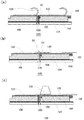
以下、屋根パネル連結構造120の組立工程の一実施形態について、図4各図に沿って説明する。実際には多くの屋根パネル100が連結されて屋根パネル連結構造を形成するが、図面の簡略化のため、図4および図5においては、2枚の屋根パネル100のみが記載されている。
Hereinafter, an embodiment of the assembly process of the roof
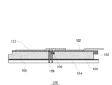
まず、下地材124上に、複数の屋根パネル100を同一平面上に敷き込んで、ビス126を用いて固定する(図4(a))。この際、凹凸部109が嵌合部(ジョイント部)となるように複数の屋根パネル100が組み合わされて、下地材124上に敷き込まれる。次に、隣り合う軟質ポリ塩化ビニルシート122が重ね合わせられる(図4(b)。その後、加熱溶着器128によって軟質ポリ塩化ビニルシート122を、その融点以上の温度(たとえば、150℃〜200℃)に加熱することによって、軟質ポリ塩化ビニルシート122の重なり合った部分が溶着され、一体の軟質ポリ塩化ビニルシートとなる(図4(c))。
First, a plurality of
このようにして、屋根パネル連結構造120(図5)を組み立てることができる。 In this way, the roof panel connection structure 120 (FIG. 5) can be assembled.
前述のように、軟質ポリ塩化ビニルシート122のうち表面材102に接着されていない領域(S2)の面積は、表面材102のうち軟質ポリ塩化ビニルシート122によって覆われておらず露出されている領域(S1)の面積よりも大きい。図4(a)および(b)に示すように、屋根パネル連結構造120が組み立てられる際、軟質ポリ塩化ビニルシート122によって覆われておらず露出されている領域(S1)は、他の屋根パネル100の軟質ポリ塩化ビニルシート122の領域(S2)によって覆われる。S2の面積はS1の面積よりも大きいため、軟質ポリ塩化ビニルシート122が熱によって溶着された際、ビス126の設置スペースとなっている表面材102の周縁部(領域S3以外の領域)に軟質ポリ塩化ビニルシート122が接着されていないにもかかわらず、一体形状となった軟質ポリ塩化ビニルシート122によって屋根パネル連結構造120の表面材が隙間無く覆われるため、屋根パネル連結構造120の高い防水性が保たれる。
As described above, the area of the soft
前述のように、軟質ポリ塩化ビニルシート122と表面材102との間の接着は、屋根パネル100が工事現場(施工現場)に搬入される前に、屋根パネル100を製造する段階で行うことができる。そのため、工事現場において軟質ポリ塩化ビニルシート122の全ての面を表面材102に貼付する必要がなく、面接着による接着力の強さを保ちつつ、工事現場での工期短縮を実現できる。また、工事現場での作業量を低減できる。
As described above, the adhesion between the soft
以上説明したように、施工現場における工期短縮と、作業性の向上と、を実現しつつ、防水性能が高い屋根パネル連結構造120が実現される
As described above, the roof
なお、この発明は上記実施の形態に限定されず、種々の変形及び応用が可能である。例えば、本実施形態においては、表面材102の二辺の周縁部が軟質ポリ塩化ビニルシート122に覆われていない形態について説明したが、図6に示すように、表面材102の一辺のみが軟質ポリ塩化ビニルシート122に覆われずに露出されており、表面材102の少なくとも一辺において、軟質ポリ塩化ビニルシート122が、表面材102の当該一辺と所定の距離を隔てて、当該一辺とそれに対応する軟質ポリ塩化ビニルシート122の一辺とが略平行になっており、S2の面積がS1の面積よりも大きければよい。
In addition, this invention is not limited to the said embodiment, A various deformation | transformation and application are possible. For example, in the present embodiment, the configuration has been described in which the peripheral portions of the two sides of the
また、本実施形態においては、防水シートとして軟質ポリ塩化ビニルシート122を用いる形態について説明したが、可撓性と防水性とを有し、表面材102と、接着剤によって接着し、加熱によって溶着できる軟質の防水シートであればよく、たとえば、軟質ポリエチレンシート、軟質ポリオレフィンシートなどであってもよい。溶着温度と溶着時間は、防水シートの材質によって適宜設定される。
In the present embodiment, the embodiment using the soft
また、本実施形態においては、断熱層として有機層108を用い、有機層108としてネオマフォーム(商標名)を用いた形態について説明したが、断熱性能を有するものであればよく、たとえば、フェノールウレタンや他のフェノールフォーム等のフェノール樹脂発泡体、押出発泡ポリスチレンフォームや硬質ウレタンフォーム、PVA(ポリビニールアルコール)やPP(ポリプロピレン)等の各種の発泡プラスチック等であってもよい。
Moreover, in this embodiment, although the
また、本実施形態においては、表面材102と裏面材104との間に断熱層である有機層108が挟まれている形態について説明したが、裏面材104と有機層108との間に耐火性能を高めるために難燃性の無機層が挟まれていてもよい。無機層106の材料としては、たとえば、石膏ボード、ケイ酸カルシウム板、炭酸カルシウム板等が用いられる。無機層106の厚さは、たとえば、7〜21mmである。
In the present embodiment, the
100 屋根パネル
102 表面材
104 裏面材
108 有機層
109 凹凸部
120 屋根パネル連結構造
122 軟質ポリ塩化ビニルシート
124 下地材
126 ビス
128 加熱溶着器
DESCRIPTION OF
Claims (3)
前記表面材と対向して設けられる裏面材と、
前記表面材と前記裏面材との間に設けられる断熱層と、
前記表面材の、前記裏面材と対向する面と反対側の面に接着される矩形状の防水シートと、
を備え、
前記防水シートの各辺の長さは、前記表面材の対応する各辺の長さよりも大きく、
前記防水シートは可撓性と熱溶着性とを有し、
前記防水シートは前記表面材の全ての辺と所定の距離を隔てて、前記表面材の各辺と該各辺に対応する前記防水シートの各辺とが略平行になるように接着され、
前記表面材の少なくとも一辺が露出されており、
前記防水シートの一部領域が前記表面材に接着されており、前記防水シートの前記一部領域以外の他の領域が前記表面材に接着されておらず、
前記他の領域の面積が前記表面材の前記一辺の周縁部の面積よりも大きい、
ことを特徴とする屋根パネル。 A rectangular surface material;
A back material provided opposite to the surface material;
A heat insulating layer provided between the surface material and the back material;
A rectangular waterproof sheet bonded to the surface of the surface material opposite to the surface facing the back material;
With
The length of each side of the waterproof sheet is larger than the length of each side corresponding to the surface material,
The waterproof sheet has flexibility and heat weldability,
The waterproof sheet is bonded such that each side of the surface material and each side of the waterproof sheet corresponding to each side are substantially parallel with a predetermined distance from all sides of the surface material,
At least one side of the surface material is exposed;
A partial region of the waterproof sheet is adhered to the surface material, and other regions other than the partial region of the waterproof sheet are not adhered to the surface material,
The area of the other region is larger than the area of the peripheral edge of the one side of the surface material,
A roof panel characterized by that.
ことを特徴とする請求項1に記載の屋根パネル。 A side perpendicular to the one side of the surface material is further exposed,
The roof panel according to claim 1.
隣り合う前記屋根パネルにおいて、前記防水シートの一部表面の上に、前記一辺を覆うように、前記防水シートの前記他の領域が載せられるように前記屋根パネルが並べられ、
前記一部表面と前記他の領域とが前記防水シートの融点以上の温度に加熱されることによって、前記一部表面と前記他の領域とが溶着されて一体の防水シートとして機能するように構成された、
ことを特徴とする屋根パネルの連結構造。 A plurality of roof panels according to claim 1 or 2 arranged on the same plane,
In the adjacent roof panels, the roof panels are arranged on the partial surface of the waterproof sheet so that the other region of the waterproof sheet is placed so as to cover the one side,
The partial surface and the other region are heated to a temperature equal to or higher than the melting point of the waterproof sheet, so that the partial surface and the other region are welded to function as an integral waterproof sheet. Was
The connection structure of the roof panel characterized by the above.
Priority Applications (1)
| Application Number | Priority Date | Filing Date | Title |
|---|---|---|---|
| JP2010286666A JP2012132264A (en) | 2010-12-22 | 2010-12-22 | Roof panel and connecting structure of roof panel |
Applications Claiming Priority (1)
| Application Number | Priority Date | Filing Date | Title |
|---|---|---|---|
| JP2010286666A JP2012132264A (en) | 2010-12-22 | 2010-12-22 | Roof panel and connecting structure of roof panel |
Publications (1)
| Publication Number | Publication Date |
|---|---|
| JP2012132264A true JP2012132264A (en) | 2012-07-12 |
Family
ID=46648157
Family Applications (1)
| Application Number | Title | Priority Date | Filing Date |
|---|---|---|---|
| JP2010286666A Pending JP2012132264A (en) | 2010-12-22 | 2010-12-22 | Roof panel and connecting structure of roof panel |
Country Status (1)
| Country | Link |
|---|---|
| JP (1) | JP2012132264A (en) |
Cited By (1)
| Publication number | Priority date | Publication date | Assignee | Title |
|---|---|---|---|---|
| JP2017527219A (en) * | 2014-09-08 | 2017-09-14 | クゥアルコム・テクノロジーズ・インコーポレイテッド | Tunneling within a network-on-chip topology |
Citations (6)
| Publication number | Priority date | Publication date | Assignee | Title |
|---|---|---|---|---|
| US4443993A (en) * | 1981-11-13 | 1984-04-24 | Mitsuboshi Belting Ltd. | Method of heat-insulating and water-proof construction |
| JPS6068122U (en) * | 1983-10-15 | 1985-05-15 | 松下電工株式会社 | breathable roof base |
| US4706435A (en) * | 1986-12-02 | 1987-11-17 | Industrial Research Development, Inc. | Prefabricated interlocking roofing system |
| JPS6326505Y2 (en) * | 1981-08-24 | 1988-07-19 | ||
| JPH11172835A (en) * | 1997-12-09 | 1999-06-29 | Gun Ei Chem Ind Co Ltd | Roof |
| JP2008008076A (en) * | 2006-06-30 | 2008-01-17 | Gantan Beauty Ind Co Ltd | Exterior finishing material and exterior finishing structure |
-
2010
- 2010-12-22 JP JP2010286666A patent/JP2012132264A/en active Pending
Patent Citations (6)
| Publication number | Priority date | Publication date | Assignee | Title |
|---|---|---|---|---|
| JPS6326505Y2 (en) * | 1981-08-24 | 1988-07-19 | ||
| US4443993A (en) * | 1981-11-13 | 1984-04-24 | Mitsuboshi Belting Ltd. | Method of heat-insulating and water-proof construction |
| JPS6068122U (en) * | 1983-10-15 | 1985-05-15 | 松下電工株式会社 | breathable roof base |
| US4706435A (en) * | 1986-12-02 | 1987-11-17 | Industrial Research Development, Inc. | Prefabricated interlocking roofing system |
| JPH11172835A (en) * | 1997-12-09 | 1999-06-29 | Gun Ei Chem Ind Co Ltd | Roof |
| JP2008008076A (en) * | 2006-06-30 | 2008-01-17 | Gantan Beauty Ind Co Ltd | Exterior finishing material and exterior finishing structure |
Cited By (1)
| Publication number | Priority date | Publication date | Assignee | Title |
|---|---|---|---|---|
| JP2017527219A (en) * | 2014-09-08 | 2017-09-14 | クゥアルコム・テクノロジーズ・インコーポレイテッド | Tunneling within a network-on-chip topology |
Similar Documents
| Publication | Publication Date | Title |
|---|---|---|
| JP2007314989A (en) | Method for installing solar cell module on flat-roof building | |
| JP5027677B2 (en) | Seat waterproof roof | |
| JP2012132264A (en) | Roof panel and connecting structure of roof panel | |
| JP2007067131A (en) | Waterproof material integrated with solar cell and construction method thereof | |
| JP6064820B2 (en) | Foundation structure of rooftop installation and foundation construction method | |
| JP5356113B2 (en) | Building outdoor panel structure | |
| JP3212836U (en) | Panel material | |
| JP5720984B2 (en) | Fireproof / waterproof exterior materials and fireproof / waterproof exterior structures | |
| JP4412087B2 (en) | Waterproof sheet solar panel set, construction method and construction structure | |
| JP4794375B2 (en) | Exterior material and exterior structure | |
| JP5089247B2 (en) | Sheet-like enclosure and construction method of sheet-like enclosure | |
| CN210049419U (en) | External wall insulation board mounting structure | |
| JP2011252345A (en) | Roof heat insulation and waterproof structure, construction method thereof and bordering fitting | |
| JP5686337B2 (en) | Fireproof / waterproof exterior construction method | |
| JP5839346B2 (en) | Thermal insulation panel and its connection structure | |
| KR101758707B1 (en) | Fireproof door having adhesive structure of dual panel and manufacturing method thereof | |
| JP4743907B2 (en) | Breathable heat insulating roof composite panel and wooden exterior heat insulating roof structure using the panel | |
| RU2431724C2 (en) | Roof and method of its manufacturing | |
| JP2023072392A (en) | Fixing bracket for roof waterproof sheet | |
| JP2013067985A (en) | Stand support material and stand support structure | |
| JP2011169003A (en) | Waterproof sheet construction structure and method for constructing the same | |
| JPH08209863A (en) | Heat insulation waterproof construction on folded plate roof and work execution method thereof | |
| JP5144130B2 (en) | Sheet-like enclosure and construction method of sheet-like enclosure | |
| JP2007277936A (en) | Waterproof heat-insulation structure and heat-insulation substrate for use therein | |
| JP5336288B2 (en) | Insulation for roof and insulation method for roof |
Legal Events
| Date | Code | Title | Description |
|---|---|---|---|
| A711 | Notification of change in applicant |
Free format text: JAPANESE INTERMEDIATE CODE: A711 Effective date: 20131031 |
|
| A621 | Written request for application examination |
Free format text: JAPANESE INTERMEDIATE CODE: A621 Effective date: 20131115 |
|
| A977 | Report on retrieval |
Free format text: JAPANESE INTERMEDIATE CODE: A971007 Effective date: 20140811 |
|
| A131 | Notification of reasons for refusal |
Free format text: JAPANESE INTERMEDIATE CODE: A131 Effective date: 20140902 |
|
| A02 | Decision of refusal |
Free format text: JAPANESE INTERMEDIATE CODE: A02 Effective date: 20150106 |