JP2012118071A - Method and apparatus for measuring distances between optical surfaces of optical system - Google Patents
Method and apparatus for measuring distances between optical surfaces of optical system Download PDFInfo
- Publication number
- JP2012118071A JP2012118071A JP2011259391A JP2011259391A JP2012118071A JP 2012118071 A JP2012118071 A JP 2012118071A JP 2011259391 A JP2011259391 A JP 2011259391A JP 2011259391 A JP2011259391 A JP 2011259391A JP 2012118071 A JP2012118071 A JP 2012118071A
- Authority
- JP
- Japan
- Prior art keywords
- optical
- optical system
- reference axis
- axis
- lens
- Prior art date
- Legal status (The legal status is an assumption and is not a legal conclusion. Google has not performed a legal analysis and makes no representation as to the accuracy of the status listed.)
- Pending
Links
Images


Classifications
-
- G—PHYSICS
- G01—MEASURING; TESTING
- G01B—MEASURING LENGTH, THICKNESS OR SIMILAR LINEAR DIMENSIONS; MEASURING ANGLES; MEASURING AREAS; MEASURING IRREGULARITIES OF SURFACES OR CONTOURS
- G01B9/00—Measuring instruments characterised by the use of optical techniques
- G01B9/02—Interferometers
- G01B9/0209—Low-coherence interferometers
-
- G—PHYSICS
- G01—MEASURING; TESTING
- G01B—MEASURING LENGTH, THICKNESS OR SIMILAR LINEAR DIMENSIONS; MEASURING ANGLES; MEASURING AREAS; MEASURING IRREGULARITIES OF SURFACES OR CONTOURS
- G01B11/00—Measuring arrangements characterised by the use of optical techniques
- G01B11/14—Measuring arrangements characterised by the use of optical techniques for measuring distance or clearance between spaced objects or spaced apertures
-
- G—PHYSICS
- G01—MEASURING; TESTING
- G01B—MEASURING LENGTH, THICKNESS OR SIMILAR LINEAR DIMENSIONS; MEASURING ANGLES; MEASURING AREAS; MEASURING IRREGULARITIES OF SURFACES OR CONTOURS
- G01B11/00—Measuring arrangements characterised by the use of optical techniques
- G01B11/26—Measuring arrangements characterised by the use of optical techniques for measuring angles or tapers; for testing the alignment of axes
- G01B11/27—Measuring arrangements characterised by the use of optical techniques for measuring angles or tapers; for testing the alignment of axes for testing the alignment of axes
- G01B11/272—Measuring arrangements characterised by the use of optical techniques for measuring angles or tapers; for testing the alignment of axes for testing the alignment of axes using photoelectric detection means
-
- G—PHYSICS
- G01—MEASURING; TESTING
- G01B—MEASURING LENGTH, THICKNESS OR SIMILAR LINEAR DIMENSIONS; MEASURING ANGLES; MEASURING AREAS; MEASURING IRREGULARITIES OF SURFACES OR CONTOURS
- G01B9/00—Measuring instruments characterised by the use of optical techniques
- G01B9/02—Interferometers
- G01B9/02015—Interferometers characterised by the beam path configuration
- G01B9/02025—Interference between three or more discrete surfaces
-
- G—PHYSICS
- G01—MEASURING; TESTING
- G01M—TESTING STATIC OR DYNAMIC BALANCE OF MACHINES OR STRUCTURES; TESTING OF STRUCTURES OR APPARATUS, NOT OTHERWISE PROVIDED FOR
- G01M11/00—Testing of optical apparatus; Testing structures by optical methods not otherwise provided for
- G01M11/02—Testing optical properties
- G01M11/0221—Testing optical properties by determining the optical axis or position of lenses
Abstract
Description
本発明は、単レンズ又は多レンズ光学系の光学面の間隔を測定する方法及び装置に関する。そのような型の間隔は、一般に光学系の光軸に対して指定される。 The present invention relates to a method and apparatus for measuring the distance between optical surfaces of a single lens or multi-lens optical system. Such mold spacing is generally specified relative to the optical axis of the optical system.
単レンズ又は多レンズ光学系の光学面の間隔を測定するために、例えば仏国特許出願公開第2803027号明細書及びR. Wilhelmらの論文「光学系のガラス厚及び空隙(air gap)のサブミクロン精度での軸上非接触測定」,Proc. of SPIE,Vol. 6616 (2007),66163P−1〜66163P−12に記載される、短コヒーレンス干渉計(short-coherence interferometer)を用いることが知られている。そのような型の干渉計は、非常に短いコヒーレンス長を有する測定光を生成する光源を有する。測定光のビーム路は、ビーム分割器を用いて参照アーム(arm)及び測定アームに分割される。測定アームで導かれる測定光は、光学系に向けられる一方、参照アームで導かれる測定光の光路長は、可動式ミラーアレイ又は同様のものを用いて変化する。光学系の光学面で反射された測定光は、参照アームで導かれる測定光と光検出器で重畳する。光検出器により記録される干渉現象から、測定光が光学面間の経路上を進む光路長の差が推測され得る。用いられる測定光の短コヒーレンス長により、参照アーム及び測定アームの光路長が一致するときにのみ、光検出器で干渉現象が起こる。 In order to measure the distance between the optical surfaces of a single-lens or multi-lens optical system, see, for example, French Patent Application Publication No. 2803027 and R.C. Wilhelm et al., “On-axis non-contact measurement of optical system glass thickness and air gap with submicron accuracy”, Proc. of SPIE, Vol. 6616 (2007), 66163P-1 to 66163P-12, it is known to use a short-coherence interferometer. Such a type of interferometer has a light source that generates measurement light having a very short coherence length. The beam path of the measurement light is divided into a reference arm (arm) and a measurement arm using a beam splitter. The measurement light guided by the measurement arm is directed to the optical system, while the optical path length of the measurement light guided by the reference arm is changed using a movable mirror array or the like. The measurement light reflected by the optical surface of the optical system is superimposed on the measurement light guided by the reference arm by the photodetector. From the interference phenomenon recorded by the photodetector, the difference in optical path length along which the measurement light travels on the path between the optical surfaces can be inferred. Due to the short coherence length of the measurement light used, an interference phenomenon occurs in the photodetector only when the optical path lengths of the reference arm and the measurement arm match.
この測定原理を用いる測定装置は、例えばFOGALE nanotech,Nimes,Franceにより販売されている。 Measuring devices using this measuring principle are sold, for example, by FOGALE nanotech, Nimes, France.
しかし、光学系の光学面の間隔を測定する短コヒーレンス干渉計の使用に関連して、測定光は、光学面にできる限り垂直に当たる必要がある。わずかに偏心(tilted)した表面の場合でさえ、わずかな光が干渉計に反射されるので、検出器では、干渉信号が生じないか、良くて−非常に低い信号対雑音比により−辛うじて検出可能な干渉信号が生じるかである。偏心(tilted)した光学面の場合に、干渉信号が十分に記録され得るときでさえ、最終的に、その信号は、望まれるような測定される光学系の光軸に沿った光学面の間隔ではなく、測定光線により定義される測定方向に沿った間隔にすぎない。この方向は光学系の光軸から大きくずれているかもしれないので、この方法で得られる測定値はあまり意味がない。 However, in connection with the use of a short coherence interferometer that measures the spacing of the optical surfaces of the optical system, the measurement light needs to strike the optical surface as perpendicular as possible. Even in the case of a slightly tilted surface, a small amount of light is reflected back to the interferometer so that the detector does not produce an interference signal, or at best-with a very low signal-to-noise ratio. Is a possible interference signal produced? In the case of a tilted optical surface, even if the interference signal can be sufficiently recorded, the signal will ultimately be the distance of the optical surface along the optical axis of the measured optical system as desired. Rather, it is only an interval along the measurement direction defined by the measurement beam. Since this direction may be greatly deviated from the optical axis of the optical system, the measurement values obtained with this method are not very meaningful.
光学系を調節するために、上述のR. Wilhelmらの論文は、最初にレーザポインタにより生成される光線を用いて光学系用チップチルトマウント(tip-tilt mount)を調節することを提案している。この目的を達成するために、平面ミラーがマウントに置かれ、光線がミラーに向けられる。マウントは、光線が自身に反射されるまで調節される。次のステップでは、光学系が、マウントに置かれ、光線が自身に反射されるように干渉計の方を向く光学面に垂直に当たるまで、偏心(tilted)させられる。 In order to adjust the optical system, R. The Wilhelm et al. Paper proposes to first adjust the tip-tilt mount for an optical system using a light beam generated by a laser pointer. To achieve this goal, a plane mirror is placed on the mount and the light beam is directed at the mirror. The mount is adjusted until the light beam is reflected by itself. In the next step, the optical system is placed on the mount and tilted until it strikes perpendicular to the optical surface facing the interferometer so that the light beam is reflected by itself.
本発明の目的は、単レンズ又は多レンズ光学系の光学面の間隔が確実かつ高精度に測定され得る装置及び方法を指定することである。 An object of the present invention is to specify an apparatus and method by which the distance between optical surfaces of a single lens or multi-lens optical system can be measured reliably and with high accuracy.
方法に関して、この目的は、本発明に従って、次のステップを有する方法により達成される。 As regards the method, this object is achieved according to the invention by a method having the following steps.
a)光学系内のすべての光学面が考慮されるように、参照軸に沿って伝わる試験光線(test-light ray)を光学系に向け、試験光線が光学系を完全に通過した後に、試験光線が位置決定(location-resolving)光学センサに当たる位置を記録することにより、光学系のセンタリング状態(centring state)を記録するステップ、
b)ステップa)で記録されたセンタリング状態を考慮して、手動又は外力補助(extraneous-force-assisted)による光学系の調節を行うステップ、
c)光学系に、参照軸に沿って伝わる測定光線を通過させるステップ、
d)光学面から反射された測定光線の一部を参照光線と干渉計で重畳させるステップ、
e)反射された一部と参照光線との間の干渉現象を記録及び評価することにより、参照軸に沿った光学面の間隔を決定するステップ。
a) A test-light ray traveling along the reference axis is directed to the optical system so that all optical surfaces in the optical system are taken into account, and after the test light has completely passed through the optical system, the test Recording the centring state of the optical system by recording the position where the light beam hits the location-resolving optical sensor;
b) adjusting the optical system manually or with extra-force-assisted taking into account the centering condition recorded in step a);
c) passing the measurement light beam traveling along the reference axis through the optical system;
d) superimposing a portion of the measurement beam reflected from the optical surface with a reference beam with an interferometer;
e) determining the spacing of the optical surfaces along the reference axis by recording and evaluating the interference phenomenon between the reflected part and the reference beam.
ステップa)でのセンタリング状態の記録により、光学系は、参照軸及び測定光線が光学面をできる限り垂直に通過するように、ステップb)で調節され得る。このことは、一方で、かなり多くの測定光が干渉計に反射され、干渉に貢献し得るという結果を有する。他方で、光学系の光軸は、干渉計が、望まれるような光軸に沿った光学面の間隔を実際に測定し、例えば必要に応じて偏心(tilted)又は移動した参照軸に沿ったものを実際に測定しないように、参照軸の近くにある。 By recording the centering state in step a), the optical system can be adjusted in step b) so that the reference axis and the measuring beam pass as vertically as possible through the optical surface. This on the one hand has the result that a considerable amount of measuring light is reflected off the interferometer and can contribute to the interference. On the other hand, the optical axis of the optical system is such that the interferometer actually measures the spacing of the optical surface along the optical axis as desired, eg along a reference axis that is tilted or moved as required. It is close to the reference axis so as not to actually measure things.
本発明に従って、センタリング状態の記録の間に、光学系のすべての光学面が考慮される。センタリング状態の記録の間に光学系の1つの表面しか考慮されないのであれば、上述のR. Wilhelmの論文に開示される方法のように、ステップb)での調節により、一般に、光学系が参照軸に対して十分な精度で正しい方向に置かれることは保証され得ない。光学球面の場合に、良くて、この表面の曲率中心が参照軸上にあることは保証され得る。しかし、この場合、光学系は、依然としてこの曲率中心の周りで偏心(tilted)しており、結果として参照軸に対して中心に置かれないかもしれない。 In accordance with the invention, all optical surfaces of the optical system are taken into account during centering recording. If only one surface of the optical system is considered during centered recording, the above-described R.P. As in the method disclosed in the Wilhelm article, the adjustment in step b) generally cannot guarantee that the optical system is correctly oriented with sufficient accuracy relative to the reference axis. In the case of an optical sphere, it can at best be guaranteed that the center of curvature of this surface is on the reference axis. In this case, however, the optical system is still tilted around this center of curvature and as a result may not be centered with respect to the reference axis.
本発明に従って、センタリング状態の記録にすべての表面が考慮される場合に限り、1つの光学面しか考慮されない場合に生じる曖昧さはなくなる。センタリング状態の記録で考慮される表面が多いほど、ステップb)で得られる参照軸に対する光学系のセンタリングは一般によくなる。この理由により、光学系のすべての光学面が考慮されれば、光学系のセンタリング状態は最も精度よく記録される。 In accordance with the present invention, the ambiguity that arises when only one optical surface is considered is eliminated only if all surfaces are considered for centered recording. The more surfaces considered in the centering state recording, the better the centering of the optical system with respect to the reference axis obtained in step b). For this reason, if all the optical surfaces of the optical system are taken into account, the centering state of the optical system is recorded with the highest accuracy.
試験光線及び光学センサにより、非常に簡便な手段を用いてすべての光学面を考慮することにより、測定光線により予め定められた参照軸に対する光学系のセンタリング状態を定性的に記録することが可能になる。これに関連して、試験光線はその光線が非垂直に当たり、結果として横方向に屈折する光学面で反射されるという事実が利用される。試験光線の横方向への屈折は、測定装置の位置決定光学センサにより記録される。光学系の光軸が参照軸に揃うほど、光学系を通過する試験光線の屈折は小さくなる。 The test beam and optical sensor allow qualitative recording of the centering state of the optical system with respect to a predetermined reference axis by means of the measurement beam by taking into account all optical surfaces using very simple means. Become. In this connection, the fact that the test beam is reflected by an optical surface that hits it non-vertically and consequently refracts laterally is utilized. The lateral refraction of the test beam is recorded by the position determining optical sensor of the measuring device. The closer the optical axis of the optical system is to the reference axis, the smaller the refraction of the test beam that passes through the optical system.
そのような透過測定(measurement in transmission)により、ステップb)での調節は、単に試験光線が位置決定光学センサに当たる位置の記録の間に、光学系が参照軸の周りを回転する場合に、特に成功する。そのような回転の間に、光学センサにより記録される位置は、参照軸の周りの円軌道を描く。ステップb)での調節は、円軌道が最小半径を有するまで継続される。光学系は、その光軸が参照軸と少なくとも十分に揃うように、参照軸に対して正しい方向に置かれる。回転は、光学センサ上の参照軸の交差点が不明であり、参照軸と試験光線が光学センサに当たる位置との間隔が確認され得ないときに、特に有利である。 With such a measurement in transmission, the adjustment in step b) is especially true when the optical system rotates around the reference axis during the recording of the position where the test beam hits the positioning optical sensor. success. During such rotation, the position recorded by the optical sensor describes a circular trajectory around the reference axis. The adjustment in step b) is continued until the circular orbit has a minimum radius. The optical system is positioned in the correct direction with respect to the reference axis so that its optical axis is at least well aligned with the reference axis. Rotation is particularly advantageous when the intersection of the reference axis on the optical sensor is unknown and the distance between the reference axis and the position where the test beam hits the optical sensor cannot be ascertained.
試験光線及び測定光線が干渉計の同じ光源により生成されれば、特に簡便である。この場合、結果として、試験光線及び測定光線は、最終的に「同じ」光線であり、異なる目的で光学系に向けられるにすぎない。 It is particularly convenient if the test light and measurement light are generated by the same light source of the interferometer. In this case, as a result, the test and measurement rays are ultimately “same” rays that are only directed to the optical system for different purposes.
装置に関して、序論で述べた目的は、参照軸に沿って表面の間隔を測定するように構成された干渉計を有する装置により達成される。装置は、加えて、光学系の少なくとも2つの光学面を考慮することにより光学系のセンタリング状態を記録するように構成されたセンタリング状態記録デバイスを有する。センタリング状態記録デバイスは、参照軸に沿って伝わる試験光線を光学系の一面に向けるように構成された試験光源と、試験光線が光学系を完全に通過した後に光学センサに当たる位置を記録するように構成された位置決定光学センサとを有する。 With respect to the device, the objectives mentioned in the introduction are achieved by a device having an interferometer configured to measure the spacing of the surface along the reference axis. The apparatus additionally has a centering state recording device configured to record the centering state of the optical system by considering at least two optical surfaces of the optical system. The centering status recording device records a test light source configured to direct a test light beam traveling along a reference axis to one surface of the optical system, and a position where the test light beam hits the optical sensor after completely passing through the optical system. A position determining optical sensor configured.
これに関連して、試験光線の光源は、間隔を測定するために光学系に向けられる測定光を生成するために、干渉計内に配置された光源でもよい。 In this connection, the light source of the test light beam may be a light source arranged in the interferometer to generate measurement light that is directed to the optical system to measure the spacing.
加えて、装置は、光学系を参照軸の周りで回転させるように構成された回転機構を示(exhibit)してもよい。 In addition, the apparatus may exhibit a rotation mechanism configured to rotate the optical system about the reference axis.
本発明のさらなる特徴及び利点は、以下の、図面に基づく実施形態の説明から明らかになるだろう。 Further features and advantages of the invention will become apparent from the following description of the embodiments based on the drawings.
1.序論
図1は、子午的断面図で、10により全体が示される光学系を示す。光学系は、7枚のレンズL1〜L7を有する。2枚のレンズL3及びL4は、隙間なく1つに接合されており、アクロマート(achromat)として用いられるダブレット(doublet)を形成する。レンズL1〜L7は、いかなる場合も不図示のレンズマウントに収容される、円筒状に研磨されたレンズ縁12を有する。
1. Introduction FIG. 1 shows an optical system, indicated generally by 10, in a meridional section. The optical system has seven lenses L1 to L7. The two lenses L3 and L4 are joined together without a gap to form a doublet used as an achromat. The lenses L1 to L7 each have a
理想的な場合に、レンズL1〜L7は、その光軸がすべて同時に円筒状のレンズ縁12の対称軸でもある共通参照軸14上にあるように、正しい方向に置かれている。参照軸14は、一般に光学系10の光軸として示される。光学系10の光学面の間隔が指定され又は測定されれば、その指定値又は測定値は、一般に光学系10の(参照軸14と一致する)光軸に沿った間隔に関係する。これに関連して、個々のレンズの光学面の間隔は、主に中心の厚みとして示される。図1では、レンズL1及びL2の中心の厚みは、それぞれdM1及びdM2により示される。空隙により相互に分離した、連続したレンズの間隔は、主に空気分離(air separation)として示される。図1では、レンズL1及びL2間の空気分離は、dL12により示される。
In an ideal case, the lenses L1-L7 are positioned in the correct direction so that their optical axes are all on the
しかし、実際の光学系では、製造及び組み立ての耐性のために、理想的な方向付けからのずれが生じる。図2は、レンズL5を例に、レンズマウント内のレンズL5のわずかな(図2では大げさに示されている)偏心(tilting)がセンタリング状態にどのように影響を与えるかを示す。ここで、レンズL5の2つのレンズ表面S51及びS52は球面であり、それぞれ図2にK51及びK52により示される曲率中心を有すると仮定する。曲率中心K51及びK52は、レンズL5の光軸を定義する。光軸は、図2に点線16により示される。この定義により、光軸16は、レンズL5の光学球面S51及びS52に対して常に垂直になる。
However, in an actual optical system, a deviation from the ideal orientation occurs due to manufacturing and assembly tolerances. FIG. 2 shows, for example, lens L5, how slight tilting (shown exaggerated in FIG. 2) of lens L5 in the lens mount affects the centering state. Here, it is assumed that the two lens surfaces S51 and S52 of the lens L5 are spherical surfaces and have the centers of curvature indicated by K51 and K52 in FIG. 2, respectively. The centers of curvature K51 and K52 define the optical axis of the lens L5. The optical axis is indicated by the dotted
非球面レンズの場合に、光軸は、非球面レンズ表面の球面部分の曲率中心により定義される。従来の非球面方程式により記述可能な非球面の場合に、曲率中心は、結果として曲率半径Rの球の中心により与えられる。方程式において、zは光軸と平行な、問題の表面の矢状(sagitta)を示し、hは光軸からの半径方向(radial)間隔を示し、c=1/Rは問題の表面の頂点の曲率を示し、kは円錐定数(conic constant)を示し、A、B、C、D、E、F、G、H、及びJは非球面定数(aspheric constant)を示す。 In the case of an aspheric lens, the optical axis is defined by the center of curvature of the spherical portion of the aspheric lens surface. In the case of an aspheric surface that can be described by a conventional aspheric equation, the center of curvature is consequently given by the center of the sphere of radius of curvature R. In the equation, z represents the surface sagitta parallel to the optical axis, h represents the radial spacing from the optical axis, and c = 1 / R is the vertex of the surface of the problem. It indicates the curvature, k indicates a conic constant, and A, B, C, D, E, F, G, H, and J indicate aspheric constants.

例えば、レンズL5の偏心(tilting)は、レンズL5がレンズマウントに正しく挿入されなかったという事実により生じているかもしれない。この理由として、例えば、レンズ縁12がその対称軸がレンズL5の光軸16と揃うように研磨されなかったという可能性が考慮される。
For example, tilting of the lens L5 may be caused by the fact that the lens L5 was not correctly inserted into the lens mount. The reason for this is, for example, the possibility that the
図1に示されるような多レンズ光学系の場合に、個々のレンズの光軸は、一般にセンタリング状態の質により、参照軸14に対してより大きく又は小さく不規則に分布する。このことは、図3に、曲率中心K11及びK12、K21及びK22、K31及びK32、並びにK41及びK42の4枚のレンズを有する光学系を例に示される。4枚のレンズの光軸は、161、162、163、及び164により示される。
In the case of a multi-lens optical system as shown in FIG. 1, the optical axes of the individual lenses are generally more or less irregularly distributed with respect to the
時折、レンズの光軸は(少なくともほぼ)共通光軸16’上に配置されているが、その光軸は参照軸14と揃っていないということも起こるかもしれない。そのような配置は、図4に示される。加えて、図3に示されるような場合があり、レンズの光軸164は、参照軸14と揃っていないが、平行である。そのような状態は、図2に示される偏心(tilting)と対照的に、しばしばレンズの偏心(decentring)として示される。
Occasionally, the optical axis of the lens is (at least approximately) disposed on the common
正確に調節されていない多レンズ光学系の光軸は、それ自体で明確には定義されない。なぜなら、曲率中心は、一般に直線上にないからである。この理由により、そのような系の「光軸」により一般に軸は理解され、レンズの曲率中心は平均してその軸から最小間隔を有する。このように理解される光軸は、結果として一種の回帰直線を表し、必要に応じて、間隔の最小化の異なる基準が適用されてもよい(例えば、算術平均、二次平均、又は問題の光学面の曲率半径の関数としての間隔の重み付け)。 The optical axis of a multi-lens optical system that is not precisely adjusted is not clearly defined by itself. This is because the center of curvature is generally not on a straight line. For this reason, the axis is generally understood by the “optical axis” of such systems, and the center of curvature of the lens on average has a minimum spacing from that axis. The optical axis understood in this way represents a kind of regression line, and different criteria for interval minimization may be applied if necessary (e.g. arithmetic mean, quadratic mean, or problematic The weighting of the spacing as a function of the radius of curvature of the optical surface).
短コヒーレンス干渉計を用いて4枚のレンズの表面の間隔を高精度に測定することが望まれる場合に、2つの問題が生じる。 Two problems arise when it is desired to measure the distance between the surfaces of four lenses with high accuracy using a short coherence interferometer.
一方で、短コヒーレンス干渉計を用いた間隔の高精度な測定は、干渉計から光学系への測定光が検査される光学系に垂直に当たるときにのみ、確実に成功する。レンズが偏心(tilted or decentred)していれば、一般に、測定光はもはや問題の光学面に垂直に当たらない。結果として、光学面から干渉計に反射される光の強度は、主に大きく弱められるので、非常に低い信号対雑音比により、測定が不能であるか、良くて比較的精度の低い測定が可能であるかである。 On the other hand, high-accuracy measurement of the interval using a short coherence interferometer is surely successful only when the measurement light from the interferometer hits the optical system to be inspected perpendicularly. If the lens is tilted or decentred, in general, the measuring light no longer strikes the optical surface in question perpendicularly. As a result, the intensity of the light reflected from the optical surface to the interferometer is largely greatly attenuated, so a very low signal-to-noise ratio makes measurement impossible or good and relatively inaccurate. Is it?
第2の問題は、問題の光学面のレンズの偏心(tilting or decentring)にもかかわらず、十分に強い干渉信号が記録され得るときでさえ、最終的に、その信号は、実際に望まれるような測定される光軸に沿った表面の間隔ではなく、その軸と無視できない角度を成す方向に沿ったものであるという事実にある。このことから生じる、光軸に沿った実際の間隔と測定された間隔との間のずれは無視できないかもしれず、レンズの偏心(tilting or decentring)が気付かれないときに、このことは特に問題になる。 The second problem is that even if a sufficiently strong interference signal can be recorded despite the tilting or decentring of the lens of the optical surface in question, the signal eventually appears to be actually desired. It is not the distance of the surface along the measured optical axis, but the fact that it is along a direction that makes a non-negligible angle with that axis. The resulting deviation between the actual and measured distance along the optical axis may not be negligible, and this is especially problematic when lens tilting or decentring is not noticed. Become.
この問題を解決することを目的として、本発明は、光学系のセンタリング状態を簡便な手段を用いて少なくとも大雑把に記録し、光学系の光軸が測定光線により予め定められた参照軸とできる限り揃うように、光学系を短コヒーレンス干渉計との関連で正しい方向に置くことを提案する。調節が行われた後に、光学系は、例えば、参照軸が個々のレンズの光軸に対して一種の回帰直線を構成するように、参照軸に対して正しい方向に置かれ得る。図3に示される配置の場合、曲率中心K11及びK12、K21及びK22、K31及びK32、並びにK41及びK42を通る回帰直線16’は、測定光線により予め定められた参照軸と一致する。しかし、光軸が参照軸に対して偏心(tilted)した直線上にあれば(図4を参照)、調節の手段により状態は確立されなければならず、光軸16’及び参照軸14の同軸方向付けは、光学系の偏心(tilting)により得られる。
In order to solve this problem, the present invention records the centering state of the optical system at least roughly using simple means, and the optical axis of the optical system is as long as possible as the reference axis predetermined by the measurement light beam. In order to align, we propose to place the optical system in the right direction in relation to the short coherence interferometer. After the adjustment has been made, the optical system can be placed in the correct direction with respect to the reference axis, for example so that the reference axis constitutes a kind of regression line with respect to the optical axis of the individual lenses. In the arrangement shown in FIG. 3, the regression lines 16 'passing through the centers of curvature K11 and K12, K21 and K22, K31 and K32, and K41 and K42 coincide with the reference axis predetermined by the measurement light beam. However, if the optical axis is on a straight line that is tilted with respect to the reference axis (see FIG. 4), the state must be established by means of adjustment and the
特に、図3に示される例が示すように、間隔測定の前のそのような調節により、必ずしもすべての光学面が参照軸14により垂直に交差されることは保証され得ない。結果として、短コヒーレンス干渉計の測定光線が、光学系の必ずしもすべての光学面に正確に垂直に当たるとは限らない。しかし、先の調節により、すべての光学面を考慮して、原理上回避不能であり、偏心(tilted or decentred)したレンズにより生じる測定誤りは、最小化され得る。
In particular, as the example shown in FIG. 3 shows, such adjustment prior to the distance measurement cannot necessarily guarantee that all optical surfaces are perpendicularly intersected by the
以下の第2及び3節では、本発明の測定装置の構造及び動作モードが、実施形態に従って説明される。この実施形態では、参照軸14に対する光学系のセンタリング状態が、透過測定により定性的に記録される。そのような定性的記述(statement)は、一般に、調節手続での実際の間隔測定の前に、光学系を参照軸14に対して正しい方向に置くことを可能にするのに十分である。
In the following
最後の第4節では、重要な方法ステップが再度要約される。 In the last section, the important method steps are summarized again.
2.測定装置の構造
図5に子午的断面図で示され、20により全体が示される測定装置は、例えば問題のCCDセンサ又は位置敏感(position-sensitive)ダイオード(PSD)である、位置決定光学センサ22と、干渉計24とを有する。測定装置20は、コンピュータ26の形式の計算ユニットと、輪状回転テーブル30により支持される試験片レセプタクル(test-specimen receptacle)28とをさらに有する。回転テーブル30は、その上に配置された試験片レセプタクル28と共に、矢印36により示されるように、モータ32を用いて参照軸34の周りを回転可能である。回転テーブル30は、モータ32と共に、測定装置20の回転機構を構成する。
2. Structure of the measuring device The measuring device shown in meridional section in FIG. 5 and indicated in its entirety by 20 is a positioning
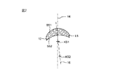
示される実施形態では、試験片レセプタクル28は、便宜上、図1に示されるレンズL3及びL4から構成される問題のダブレットである、試験片38を支持する。この試験片38の3つの光学面は、S1、S2、及びS3により示される。もちろん、かなり多くのレンズを有する試験片が検査されてもよい。図5の表現では、試験片38は、それぞれK1、K2、及びK3により示される、表面S1、S2、及びS3の曲率中心が参照軸34上にないように、偏心(decentred)していると仮定する。むしろ、曲率中心K1、K2、及びK3は、ほぼ試験片38の光軸40上にあるが、参照軸34に対して偏心(tilted)している。
In the embodiment shown,
干渉計24は、短コヒーレンス干渉計の形式をとり、この目的のために、レーザ光の光源に比べてスペクトル的に広帯域であり、例えば高輝度(superluminescent)ダイオードである、光源44を有する。比較的広いスペクトル帯域により、光源44により生成される光は、レーザ光の光源により生成される光よりもかなり短いコヒーレンス長を有する。代替方法として、極短光パルスを生成するレーザ光の光源が用いられてもよい。なぜなら、そのような光パルスは、短コヒーレンス長を有するからである。
The
光源44により生成される測定光は、コリメータレンズ46により集光され、測定光を試験片38に向けられる測定光線50と、参照光線52とに分割するビーム分割キューブ48に向けられる。光線50及び52は、より識別可能にするために、鎖線により示される軸に対するオフセットで描かれている。しかし、実際その光線は、正確にその軸に沿っている。このことは、参照軸34に沿って正確に伝わる、試験片38に向けられる測定光線50に対して特に有効である。
The measurement light generated by the
参照光線52は、アクチュエータ56を用いてビーム方向に沿って移動可能なミラー54により、自身に反射される。このように、ビーム分割キューブ48とミラー54との間の、参照光線52の光路長は変更され得る。
The
試験片38に向けられる測定光線50は、参照軸34に沿って試験片を通過する。光学面S1、S2、及びS3の各々で反射された測定光線の一部60は、ビーム分割キューブ48に戻り、一部は光検出器62の方向に反射される。反射された測定光線の一部60は、ミラー54から反射された参照光線52と重畳する。
A measuring
反射された測定光線の一部60及び参照光線52が光検出器62に向かって進んだときの光路長の差が、光源44により生成される測定光のコヒーレンス長の10倍であれば、光検出器62により記録される干渉現象が起こる。光源44により生成される測定光のコヒーレンス長が短いので、光検出器62は、ミラー54により進められる経路の関数として、前述の条件が満たされれば厳しく制限される出力信号を生成する。
If the difference in the optical path length when the reflected part of the
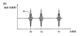
図6は、光検出器62により記録される強度Iが、参照光線52が進む光路長OPL上に描かれているグラフの例を示す。この光路長は、測定の間にミラー54を移動することにより変化する。反射された測定光線の一部60及び参照光線52の光路長が一致するときはいつでも、干渉信号は光検出器62で記録され得る。横座標上に、光検出器62で対応する干渉信号をもたらす表面S3、S2、及びS1が指定されている。
FIG. 6 shows an example of a graph in which the intensity I recorded by the
測定信号の包絡線63の最大値の位置から、レンズ材料の群屈折率を考慮して、表面S1、S2、及びS3の間隔が非常に高い精度で決定され得る。
From the position of the maximum value of the
実際の測定信号の場合に、さらなる干渉信号は、一般に包絡線63間にあり、例えば、試験片38内での複数の反射によりもたらされ、時には比較的高いレベルに達するかもしれない。そのような干渉信号が測定を妨げないように、包絡線63の周りに置かれる弁別窓(discriminator window)を用いて、干渉信号はマスクされ得る。弁別窓は、干渉信号が予期される位置に自動的に、優先的に置かれ、基礎として表面S1、S2、及びS3の望まれる間隔をとる。できる限り多くの測定光が試験片38の表面S1、S2、及びS3から反射され、光検出器62に入力され得るために、試験片に向けられる測定光線50は、コリメータレンズ46を用いて試験片38に適合させられ得る。短コヒーレンス干渉計を用いた透明体の厚みの検査に関するさらなる詳細は、仏国特許出願公開第2803021号明細書から収集され得る。原理上適切な短コヒーレンス干渉計は、とりわけFOGALE nanotech,Nimes,Franceにより販売されている。
In the case of an actual measurement signal, further interference signals are generally between the
3.測定の順序
以下では、本発明の測定方法が、図7〜9を参照してより詳細に説明される。
3. Order of measurement In the following, the measuring method of the present invention will be described in more detail with reference to FIGS.
a)一度だけの方向付け
最初に、試験片38に向けられる、干渉計24の測定光線50は、回転テーブル30の回転軸により定義される参照軸34に沿って正確に伝わると仮定する。そのような調節は、測定装置を初めて作動させる前に、一度だけ行われる。
a) One-time orientation Initially, it is assumed that the
この一度の方向付けのために、例えば平面ミラーが回転テーブル30の開口部に置かれてもよい。参照アームは、例えばミラー54を偏心(tilting)させることにより、動作から外される。干渉計24及び回転テーブル30は、光検出器で記録される信号が最大強度を有するまで、角度に関して相互に正しい方向に置かれる。このことから、測定光線50は平面ミラーで自身に反射され、平面ミラーは結果として参照軸34に対して垂直に正しい方向に置かれることが推測され得る。回転テーブルの回転軸は、結果として参照軸34と平行になる。
For this one-way orientation, for example, a plane mirror may be placed at the opening of the
次のステップでは、平面ミラーが球面レンズにより置き換えられる。干渉計24及び回転テーブル30は、干渉信号が最大強度を有するまで、参照軸34に対して垂直に相互に移動される。このことから、測定光線50は球面レンズで自身に反射され、球面レンズは結果としてその中心が参照軸34上に置かれることが推測され得る。回転テーブルの回転軸は、参照軸34に対して同軸上になる。
In the next step, the plane mirror is replaced by a spherical lens.
上述の2つの調節ステップは、必要に応じて、最適な方向付けが達成されるまで、(何度も)繰り返されてよい。 The two adjustment steps described above may be repeated (as many times) as needed until optimal orientation is achieved.
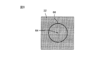
光学センサ22は、その座標原点が参照軸34上にあるように、優先的に調節される。そのような調節は、センサ表面に割り当てられる座標系の再配置により、純粋に計算的に行われてもよい。
The
b)試験片38の調節
実際の間隔測定の前に行われなければならない試験片38の調節を説明するために、測定装置20の必須要素を拡大して示す図7が参照される。
b) Adjustment of the
最初に、干渉計24により生成される測定光線50は、試験片38の一面に向けられる。図5及び7で仮定されている光軸40の偏心(tilting)の場合に、表面S1、S2、及びS3は、参照軸34及び測定光線50がもはや表面S1、S2、及びS3を垂直に通過しないように、再配置されている。結果として、表面S1、S2、及びS3で測定光線50の屈折が起こり、その光線は試験片38から参照軸34に対して斜めに離れるという結果になる。結果として、測定光線50は、参照軸34の交差点64ではなく、交差点64から離れた位置66で、光学センサ22に当たる。この位置66は、光学センサ22により記録され、ディスプレイ画面70への表示のためにコンピュータ26に伝達される。
Initially, the
原理上、試験片38のセンタリング状態に関する定性的記述は、単に位置66の交差点64からの間隔から作成され得る。この目的のために、光学センサ22の交差点64の位置は、適切な手続を用いて前もって決定される必要がある。試験片38が手動により又は(必要に応じて、外力補助)マニピュレータを用いて試験片レセプタクル28内で偏心(tilted)及び/又は再配置され、その方法で測定光線50が光学センサ22に当たる位置66が観測されれば、調節は位置66及び交差点64の間隔が最小になるまで継続され得る。
In principle, a qualitative description of the centering condition of the
試験片38が回転テーブル28を用いて参照軸34の周りを回転すれば、調節は(特に、光学センサ22上の交差点64の位置が不明であるときに)より成功する。位置66は、図8に光学センサ22の上面図で示されるように、参照軸34の周りで円軌道68上を移動する。参照軸34に対する試験片38の最適な方向付けは、図9に示されるように、光学センサ上に描かれる円68’の半径が最小であるときに得られる。
If the
上述の調節を行い得るために、測定光線50の代わりに、異なる光源により生成される試験光線が試験片38を通って光学センサ22に向けられ得ることが理解されるだろう。
It will be appreciated that instead of the
c)間隔測定
上述の調節の後に、試験片38は、光軸40が参照軸34と揃うように、参照軸34に対して正しい方向に置かれている。レンズL3及びL4は、参照軸34に対してわずかに偏心(tilted)しているだけである。表面S1、S2、及びS3の間隔が、干渉計24を用いて、図5を参照して上述した方法で測定されれば、測定光線50は、表面S1、S2、及びS3をほぼ垂直に通過する。結果として、一方で、表面S1、S2、及びS3から反射される測定光線は、最大強度を有し、この理由により、参照光線52と重畳して光検出器62で明確に識別可能な干渉信号を生成することが保証される。他方で、参照軸34に対する試験片38の光軸40の方向付けにより、光学面S1、S2、及びS3の間隔は、実際に試験片38の光軸に沿って測定されることが保証される。
c) Interval Measurement After the above adjustment, the
5.重要な方法ステップの要約
以下では、図10が参照される。図10は、本発明の方法の必須ステップが列挙されるフローチャートを示す。第1ステップST1では、試験片38又はごく一般に単レンズ若しくは多レンズ光学系の光学面のうち少なくとも2つ、優先的にすべてを考慮して、そのセンタリング状態が記録される。第2ステップST2では、試験片38が、その光軸40が参照軸38とできる限り正確に揃うように、優先的に調節される。第3ステップST3では、試験片38が、測定光線50を通過させられる。第4ステップST4では、試験片38から反射された測定光が、参照光と干渉計24で重畳させられる。第5ステップST5では、表面間隔が、光検出器62で干渉現象を評価することにより決定される。
5. Summary of Important Method Steps In the following, reference is made to FIG. FIG. 10 shows a flowchart listing the essential steps of the method of the invention. In the first step ST1, the centering state is recorded in consideration of at least two of the optical surfaces of the
Claims (8)
a)前記光学系(38)内のすべての光学面が考慮されるように、参照軸(34)に沿って伝わる試験光線(50)を前記光学系(38)に向け、前記試験光線が前記光学系(38)を完全に通過した後に、前記試験光線が位置決定光学センサ(22)に当たる位置(66)を記録することにより、前記光学系(38)のセンタリング状態を記録するステップと、
b)ステップa)で記録された前記センタリング状態を考慮して、前記光学系(38)を調節するステップと、
c)前記光学系(38)に、前記参照軸(34)に沿って伝わる測定光線(50)を通過させるステップと、
d)前記光学面(S1、S2、S3)から反射された前記測定光線の一部(60)を参照光線(52)と干渉計(24)で重畳させるステップと、
e)前記反射された一部(60)と前記参照光線(52)との間の干渉現象を記録及び評価することにより、前記参照軸(34)に沿った前記光学面(S1、S2、S3)の前記間隔を決定するステップと、を有する方法。 A method for measuring the distance between optical surfaces (S1, S2, S3) of a single lens or multi-lens optical system (38),
a) directing a test beam (50) traveling along a reference axis (34) to the optical system (38) so that all optical surfaces in the optical system (38) are taken into account; Recording the centering state of the optical system (38) by recording the position (66) where the test beam strikes the positioning optical sensor (22) after completely passing through the optical system (38);
b) adjusting the optical system (38) taking into account the centering state recorded in step a);
c) passing the measuring beam (50) transmitted along the reference axis (34) through the optical system (38);
d) superimposing a portion (60) of the measurement beam reflected from the optical surface (S1, S2, S3) with a reference beam (52) and an interferometer (24);
e) recording and evaluating the interference phenomenon between the reflected part (60) and the reference beam (52), so that the optical surfaces (S1, S2, S3) along the reference axis (34); And determining the interval.
a)参照軸(34)に沿って前記表面(S1、S2、S3)の間隔を測定するように構成された干渉計(24)と、
b)前記光学系(38)のすべての光学面(S1、S2、S3)を考慮することにより、前記光学系(38)のセンタリング状態を記録するように構成されたセンタリング状態記録デバイス(44、22;72)と、を有し、
前記センタリング状態記録デバイスは、
前記参照軸(34)に沿って伝わる試験光線(50)を前記光学系(38)の一面に向けるように構成された試験光源(44)と、
前記試験光線(50)が前記光学系(38)を完全に通過した後に前記光学センサ(22)に当たる位置を記録するように構成された位置決定光学センサ(22)と、を有する、装置。 An apparatus for measuring the distance between the optical surfaces (S1, S2, S3) of the multi-lens optical system (38),
a) an interferometer (24) configured to measure the spacing of the surfaces (S1, S2, S3) along a reference axis (34);
b) A centering state recording device (44, configured to record the centering state of the optical system (38) by considering all the optical surfaces (S1, S2, S3) of the optical system (38). 22; 72), and
The centering state recording device includes:
A test light source (44) configured to direct a test beam (50) traveling along the reference axis (34) to one surface of the optical system (38);
A position determining optical sensor (22) configured to record a position where the test beam (50) hits the optical sensor (22) after completely passing through the optical system (38).
Applications Claiming Priority (2)
| Application Number | Priority Date | Filing Date | Title |
|---|---|---|---|
| DE102010053423.4 | 2010-11-29 | ||
| DE102010053423A DE102010053423A1 (en) | 2010-11-29 | 2010-11-29 | Method and device for measuring distances between optical surfaces of an optical system |
Publications (1)
| Publication Number | Publication Date |
|---|---|
| JP2012118071A true JP2012118071A (en) | 2012-06-21 |
Family
ID=45047537
Family Applications (1)
| Application Number | Title | Priority Date | Filing Date |
|---|---|---|---|
| JP2011259391A Pending JP2012118071A (en) | 2010-11-29 | 2011-11-28 | Method and apparatus for measuring distances between optical surfaces of optical system |
Country Status (5)
| Country | Link |
|---|---|
| US (1) | US8760666B2 (en) |
| EP (1) | EP2458321B1 (en) |
| JP (1) | JP2012118071A (en) |
| DE (1) | DE102010053423A1 (en) |
| PL (1) | PL2458321T3 (en) |
Families Citing this family (14)
| Publication number | Priority date | Publication date | Assignee | Title |
|---|---|---|---|---|
| DE102010053422B3 (en) * | 2010-11-29 | 2012-03-29 | Trioptics Gmbh | Measurement of the positions of centers of curvature of optical surfaces of a multi-lens optical system |
| US8944001B2 (en) * | 2013-02-18 | 2015-02-03 | Nordson Corporation | Automated position locator for a height sensor in a dispensing system |
| DE102014208636B4 (en) * | 2014-05-08 | 2018-06-28 | Asphericon Gmbh | Method and device for measuring a decentering and tilting of surfaces of an optical element |
| CN105108186A (en) * | 2015-06-25 | 2015-12-02 | 中国科学院西安光学精密机械研究所 | Error separation method of lens based on centering machining |
| DE102016014834B3 (en) * | 2016-12-14 | 2018-04-19 | Innolite Gmbh | Method for ultra-precise centering of a transmissive or reflective optic, in particular a lens with an aspherical or free-form front lens surface |
| CN109425312B (en) * | 2017-09-01 | 2021-12-03 | 宁波舜宇车载光学技术有限公司 | Eccentricity testing device and method |
| CN108734766B (en) * | 2018-05-17 | 2022-04-08 | 业成科技(成都)有限公司 | Method for evaluating curvature radius of curved surface device |
| FR3093560B1 (en) * | 2019-03-05 | 2021-10-29 | Fogale Nanotech | Method and device for measuring interfaces of an optical element |
| CN110057552B (en) * | 2019-04-23 | 2020-11-06 | 芋头科技(杭州)有限公司 | Virtual image distance measuring method, device, equipment, controller and medium |
| CN110737103B (en) * | 2019-10-31 | 2022-03-08 | 中国科学院长春光学精密机械与物理研究所 | Large-caliber off-axis catadioptric multichannel optical system assembling and adjusting method |
| CN111220095B (en) * | 2019-12-06 | 2021-08-03 | 凌云光技术股份有限公司 | Method and device for detecting verticality of optical axis of divergent light beam with high precision |
| DE102020107298A1 (en) | 2020-03-17 | 2021-09-23 | Berliner Glas GmbH | Method and adjustment device for aligning optical lenses |
| CN112526697B (en) * | 2020-12-10 | 2022-07-22 | 业成科技(成都)有限公司 | Lens alignment method |
| US11860380B1 (en) * | 2023-08-15 | 2024-01-02 | Mloptic Corp. | Lens assembly alignment tool |
Citations (3)
| Publication number | Priority date | Publication date | Assignee | Title |
|---|---|---|---|---|
| JPH06194122A (en) * | 1992-12-24 | 1994-07-15 | Shimadzu Corp | Decentering measuring device |
| JP2005147703A (en) * | 2003-11-11 | 2005-06-09 | Olympus Corp | Device and method for measuring surface distance |
| JP2007046971A (en) * | 2005-08-09 | 2007-02-22 | Olympus Corp | Instrument and method for measuring eccentricity of lens |
Family Cites Families (12)
| Publication number | Priority date | Publication date | Assignee | Title |
|---|---|---|---|---|
| FR2803027B1 (en) | 1999-12-23 | 2003-03-21 | Nanotec Solution | OPTICAL MEASUREMENT METHOD FOR NON-CONTACT MEASUREMENT OF THICKNESS OF TRANSLUCENT MATERIALS, AND ASSOCIATED DEVICE |
| FR2803021B1 (en) | 1999-12-27 | 2002-05-24 | Soudure Autogene Francaise | OXY-FUEL TORCH |
| JP2002213926A (en) * | 2001-01-22 | 2002-07-31 | Nikon Corp | Instrument and method for measuring space, method of manufacturing optical system, and interferometer |
| US7046351B2 (en) * | 2002-05-20 | 2006-05-16 | Pentax Corporation | Method and apparatus for measuring eccentricity of optical lens, and method and apparatus for centering and edging optical lens |
| JP2004069594A (en) * | 2002-08-08 | 2004-03-04 | Olympus Corp | Apparatus and method for measuring amount of eccentricity |
| DE102004029735C5 (en) | 2004-06-21 | 2011-09-15 | Trioptics Gmbh | Method for measuring optical surfaces within a multi-line arrangement |
| US7133225B1 (en) | 2004-10-18 | 2006-11-07 | Carl Zeiss Smt Ag | Method of manufacturing an optical system |
| DE102005013571A1 (en) | 2005-03-23 | 2006-06-14 | Carl Zeiss Smt Ag | Production of an optical lens with an aspheric surface, e.g. for an astronomical telescope, rotates the substrate on a table for measurement at rotary positions of the reference and symmetry axes in relation to the table axis |
| US7643149B2 (en) | 2005-05-24 | 2010-01-05 | Carl Zeiss Smt Ag | Method of aligning an optical system |
| JP4880513B2 (en) * | 2007-03-29 | 2012-02-22 | 富士フイルム株式会社 | Method and apparatus for measuring surface deviation of aspherical lens |
| CN101334334B (en) * | 2007-06-25 | 2010-06-02 | 佛山普立华科技有限公司 | Lens eccentricity detection system |
| CN101373167B (en) * | 2007-08-24 | 2010-04-07 | 鸿富锦精密工业(深圳)有限公司 | System and method for detecting eccentricity of glasses lens |
-
2010
- 2010-11-29 DE DE102010053423A patent/DE102010053423A1/en not_active Withdrawn
-
2011
- 2011-11-19 EP EP11009186.5A patent/EP2458321B1/en active Active
- 2011-11-19 PL PL11009186T patent/PL2458321T3/en unknown
- 2011-11-22 US US13/302,675 patent/US8760666B2/en active Active
- 2011-11-28 JP JP2011259391A patent/JP2012118071A/en active Pending
Patent Citations (3)
| Publication number | Priority date | Publication date | Assignee | Title |
|---|---|---|---|---|
| JPH06194122A (en) * | 1992-12-24 | 1994-07-15 | Shimadzu Corp | Decentering measuring device |
| JP2005147703A (en) * | 2003-11-11 | 2005-06-09 | Olympus Corp | Device and method for measuring surface distance |
| JP2007046971A (en) * | 2005-08-09 | 2007-02-22 | Olympus Corp | Instrument and method for measuring eccentricity of lens |
Also Published As
| Publication number | Publication date |
|---|---|
| PL2458321T3 (en) | 2014-08-29 |
| EP2458321B1 (en) | 2014-01-08 |
| DE102010053423A1 (en) | 2012-05-31 |
| US8760666B2 (en) | 2014-06-24 |
| EP2458321A1 (en) | 2012-05-30 |
| US20120133951A1 (en) | 2012-05-31 |
Similar Documents
| Publication | Publication Date | Title |
|---|---|---|
| JP2012118071A (en) | Method and apparatus for measuring distances between optical surfaces of optical system | |
| JP5902448B2 (en) | Measurement of the center of curvature of the optical surface of a multi-lens optical system | |
| EP2369319B1 (en) | Aspheric object measuring method and apparatus | |
| JP2005509875A (en) | Aspheric and wavefront scanning interferometers | |
| JP2004530898A (en) | Interferometric scanning for aspheric surfaces and wavefronts | |
| CN109406105B (en) | Virtual image detection method and detection system | |
| CN112325802A (en) | Two-dimensional small-angle laser measurement method and device based on common-path difference and self-zero calibration | |
| WO2012132930A1 (en) | Lens measurement device | |
| JP2010025876A (en) | Micro-distance measuring method and device | |
| JPH1089935A (en) | Device for measuring aspherical interference | |
| JP2960905B2 (en) | Apparatus for measuring flying height and azimuth of magnetic head with respect to transparent medium based on leaky total internal reflection | |
| TWI595252B (en) | Distance measurement device and distance measuring method thereof | |
| JP3230983B2 (en) | Subject position adjustment method for lightwave interference device | |
| JP2002206915A (en) | Abscissa calibration method for facial shape measuring device and facial shape measuring device | |
| JP2002048673A (en) | Physical quantity measuring method of optical element or optical system | |
| JP2865337B2 (en) | Optical measuring device | |
| JP3702733B2 (en) | Alignment method and mechanism of optical inspection apparatus | |
| CN109341587A (en) | Splicing measuring device and method | |
| JP2000230883A (en) | Decentering measuring apparatus and its adjusting method | |
| CN108663124B (en) | Detection device and method of wavefront sensor | |
| JPH1194700A (en) | Measuring device and method for lens | |
| CN220304798U (en) | Right angle error detection auxiliary device for pentaprism | |
| CN201532193U (en) | Device for detecting incidence angles of reflecting mirror | |
| JP3164444B2 (en) | Interference measurement method | |
| JP2814255B2 (en) | How to measure the refractive index distribution |
Legal Events
| Date | Code | Title | Description |
|---|---|---|---|
| A621 | Written request for application examination |
Free format text: JAPANESE INTERMEDIATE CODE: A621 Effective date: 20140925 |
|
| A977 | Report on retrieval |
Free format text: JAPANESE INTERMEDIATE CODE: A971007 Effective date: 20150729 |
|
| A131 | Notification of reasons for refusal |
Free format text: JAPANESE INTERMEDIATE CODE: A131 Effective date: 20150804 |
|
| A601 | Written request for extension of time |
Free format text: JAPANESE INTERMEDIATE CODE: A601 Effective date: 20151102 |
|
| A521 | Written amendment |
Free format text: JAPANESE INTERMEDIATE CODE: A523 Effective date: 20151127 |
|
| A02 | Decision of refusal |
Free format text: JAPANESE INTERMEDIATE CODE: A02 Effective date: 20160426 |