JP2012116048A - Portable cutter - Google Patents
Portable cutter Download PDFInfo
- Publication number
- JP2012116048A JP2012116048A JP2010266461A JP2010266461A JP2012116048A JP 2012116048 A JP2012116048 A JP 2012116048A JP 2010266461 A JP2010266461 A JP 2010266461A JP 2010266461 A JP2010266461 A JP 2010266461A JP 2012116048 A JP2012116048 A JP 2012116048A
- Authority
- JP
- Japan
- Prior art keywords
- main base
- base
- contact surface
- cutting machine
- cut
- Prior art date
- Legal status (The legal status is an assumption and is not a legal conclusion. Google has not performed a legal analysis and makes no representation as to the accuracy of the status listed.)
- Pending
Links
Images


Landscapes
- Sawing (AREA)
Abstract
Description
本発明は携帯用切断機に関し、特に主ベースに対して着脱可能な補助ベースを備える携帯用切断機に関する。 The present invention relates to a portable cutting machine, and more particularly to a portable cutting machine including an auxiliary base that can be attached to and detached from a main base.
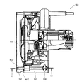
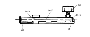
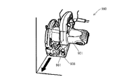
図11乃至図14に示されるように、主ベース961に対して着脱可能な補助ベース962を備える携帯用切断機900が知られている(例えば、特許文献1参照)。携帯用切断機900は、図13及び図14に示されるように壁際の切断(以下際切りと呼ぶ)を行う際には、補助ベース962を主ベース961から取外して切断作業を行う。補助ベース962を取外すことにより、本体901を鋸刃903側と反対に傾倒して、主ベース961の側面961Cと鋸刃903の切断位置を合わせることができる。一方、通常の切断作業時には、携帯用切断機900は補助ベース962を主ベース961に装着した状態で使用される。補助ベース962を主ベース961に装着する構成として、主ベース961に形成された案内孔961a、961b(図12)に補助ベースに設けられた棒部材962Fを挿入してネジ908等で締付けて固定する構成がある。
As shown in FIGS. 11 to 14, a
携帯用切断機は、ベース底面を被切断材上において摺動しながら、切断作業を行うため、ベース底面は平らであることが要求される。しかしながら、上述のような通常作業時に補助ベースを主ベースに装着して用いる携帯用切断機では、主ベースと補助ベースとを精度よく取付けることが難しく、主ベースの底面と補助ベースの底面とに段差が生じるという問題があった。このような段差により、携帯用切断機を被切断材上において摺動させようとすると、被切断材の一部に引っかかったり本体が被切断部材に対して傾いてしまうという問題があった。 Since the portable cutting machine performs a cutting operation while sliding the base bottom surface on the material to be cut, the base bottom surface is required to be flat. However, it is difficult to attach the main base and the auxiliary base with high precision in the portable cutting machine that is used by attaching the auxiliary base to the main base during the normal operation as described above, and the bottom surface of the main base and the bottom surface of the auxiliary base are difficult to attach. There was a problem that a step occurred. When the portable cutting machine is slid on the material to be cut due to such a step, there is a problem that the material is caught on a part of the material to be cut or the main body is inclined with respect to the member to be cut.
よって本発明は、補助ベースが主ベースに装着されている際に、主ベースの底面と補助ベースの底面とによって段差が生じない作業性の良い携帯用切断機を提供することを目的とする。 Accordingly, an object of the present invention is to provide a portable cutting machine with good workability in which no step is generated between the bottom surface of the main base and the bottom surface of the auxiliary base when the auxiliary base is mounted on the main base.
上記課題を解決するために本発明は、モータを保持するハウジングと、該モータにより駆動されて被切断部材を切断する切断刃と、該ハウジングに接続され、該被切断部材に当接する第1当接面を有し、該第1当接面から該切断刃を突出させる開口部が形成される主ベースと、該主ベースに着脱可能に設けられ、該切断刃に対して該主ベースの反対側に設けられ、該第1当接面と共に該被切断部材に当接可能な第2当接面を有する補助ベースと、該第1当接面に交差する方向における該第2当接面の位置を調整する位置調整機構と、を備えることを特徴とする携帯用切断機を提供する。 In order to solve the above problems, the present invention provides a housing that holds a motor, a cutting blade that is driven by the motor to cut a member to be cut, and a first contact that is connected to the housing and contacts the member to be cut. A main base having a contact surface and having an opening for projecting the cutting blade from the first abutting surface; and detachably provided on the main base, opposite the main base with respect to the cutting blade An auxiliary base having a second abutting surface provided on the side and capable of abutting on the member to be cut together with the first abutting surface, and the second abutting surface in a direction intersecting the first abutting surface. A portable cutting machine comprising: a position adjusting mechanism for adjusting a position.
このような携帯用切断機によれば、主ベースの第1当接面に交差する方向における補助ベースの第2当接面の位置を調整して、第1当接面と第2当接面とを面一とすることができる。よって、がたつきのない安定した状態で被切断部材を切断することができ、作業性の良い携帯用切断機を提供することができる。 According to such a portable cutting machine, the first contact surface and the second contact surface are adjusted by adjusting the position of the second contact surface of the auxiliary base in the direction intersecting the first contact surface of the main base. Can be made flush with each other. Therefore, the member to be cut can be cut in a stable state without rattling, and a portable cutting machine with good workability can be provided.
上記構成の携帯用切断機において、該位置調整機構は、該第1当接面に略直交する方向における該第2当接面の位置を調整する位置調整手段と、該主ベースに対する該補助ベースの装着方向における所望の位置において、該補助ベースを該主ベースに対して移動不能に固定する固定手段を備えることが好ましい。 In the portable cutting machine configured as described above, the position adjusting mechanism includes position adjusting means for adjusting the position of the second contact surface in a direction substantially orthogonal to the first contact surface, and the auxiliary base with respect to the main base. It is preferable to provide fixing means for fixing the auxiliary base to the main base so as not to move at a desired position in the mounting direction.
このような構成によれば、作業者は、第2当接面と第1当接面との位置を調整するとともに、所望の位置において補助ベースを主ベースに固定することができる。よって、安定して切断作業を行うことができる。 According to such a configuration, the operator can adjust the positions of the second contact surface and the first contact surface and can fix the auxiliary base to the main base at a desired position. Therefore, the cutting operation can be performed stably.
また、該位置調整機構は、複数の該位置調整手段と、複数の該固定手段とを有することが好ましい。 The position adjusting mechanism preferably includes a plurality of the position adjusting means and a plurality of the fixing means.
このような構成によれば、複数の位置調整手段及び固定手段を有するので、第1当接面に対する第2当接面の位置決めをより精度よく行うことができる。 According to such a configuration, since the plurality of position adjusting means and the fixing means are provided, the positioning of the second contact surface with respect to the first contact surface can be performed with higher accuracy.
また、該位置調整機構は、該第1当接面に略直交する方向における該第2当接面の位置を調整するとともに、該補助ベースを該主ベースに対して移動不能に固定する位置調整固定手段を有することが好ましい。 The position adjustment mechanism adjusts the position of the second contact surface in a direction substantially orthogonal to the first contact surface, and adjusts the position of the auxiliary base so as not to move relative to the main base. It is preferable to have fixing means.
このような構成によれば、補助ベースの第2当接面の位置調整と補助ベースの主ベースへの固定との両方を同一の位置調整固定手段によって行うので、操作性の良い携帯用切断機を実現することができる。また、装置全体の大型化を抑制することができる。 According to such a configuration, both the position adjustment of the second abutment surface of the auxiliary base and the fixing of the auxiliary base to the main base are performed by the same position adjustment fixing means. Can be realized. Moreover, the enlargement of the whole apparatus can be suppressed.
また、該位置調整機構は、該切断刃による該被切断部材の切断が進行する方向において該切断刃よりも前方に設けられることが好ましい。 Further, the position adjusting mechanism is preferably provided in front of the cutting blade in a direction in which the cutting of the member to be cut by the cutting blade proceeds.
このような構成によれば、位置調整機構は切断進行方向において切断刃よりも前方に設けられているので、第1当接面及び第2当接面のうち前端部のみを被切断部材に乗せて切断作業を行う場合に安定した切断動作を行うことができる。 According to such a configuration, since the position adjusting mechanism is provided in front of the cutting blade in the cutting progress direction, only the front end portion of the first contact surface and the second contact surface is placed on the member to be cut. Thus, a stable cutting operation can be performed when cutting work.
本発明の携帯用切断機によれば、補助ベースが主ベースに装着されている際のがたつきを防止し作業性の向上が実現できる。 According to the portable cutting machine of the present invention, it is possible to prevent rattling when the auxiliary base is mounted on the main base and to improve workability.
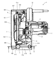
本発明の第1の実施の形態による携帯用切断機である丸のこ1は、図1及び図2に示されるように、ハウジング2と、丸のこ刃3と、ソーカバー4と、モータ5と、ベース部6とから主に構成されている。
As shown in FIGS. 1 and 2, a circular saw 1 that is a portable cutting machine according to the first embodiment of the present invention includes a
ハウジング2は、モータ5を保持して収容する収容部21と、収容部21と一体のハンドル22とから主に構成されている。ハンドル22には、モータ5の駆動を制御する図示せぬスイッチが設けられている。
The
ソーカバー4は、モータ5に駆動される図示せぬ駆動系を収容し、この駆動系により丸のこ刃3が回転駆動される。丸のこ刃3は回転することにより木材等の被切断部材を切断する。ソーカバー4は、ハンドル22に対して反収容部21側においてハウジング2に接続されている。ソーカバー4は金属製であって、丸のこ刃3の略半分を覆っている。
The saw cover 4 houses a drive system (not shown) driven by the
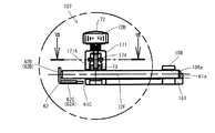
ベース部6はハウジング2の下方に接続されている。ベース部6は、ハウジング2に接続される主ベース61と、主ベース61に対して着脱可能な補助ベース62とを備える。主ベース61は金属製であって略長方形の板材より構成されている。主ベース61は、丸のこ刃3を回転可能に支持し、長手方向が丸のこ刃3の切断方向と一致するように配置されている。補助ベース62は、略L字形の金属板であって、丸のこ刃3に対して主ベース61の反対側に配置されている。補助ベース62は、主ベース61よりも幅が小さく長さが略等しい長方形の板状である底部62Aと、底部62Aに対して略直交する方向に延びる側壁62Bとを備えている。底部62Aは、後述の主ベース61の底面61B(図2)と共に被切断部材に当接可能な底面62C(図2)を有している。側壁62Bの前端部62D及び後端部62Eには、底部62Aに一部対向しながら略平行に延びる略円柱形状の棒部材62Fが設けられている。棒部材62Fは、底部62Aの幅と主ベース61の幅とを合わせた長さに略等しい長さを有している。
The
主ベース61は、ハウジング2に接続される上面61Aと、上面61Aに対向し被切断材に当接可能な底面61B(図2)と、丸のこ刃3の近傍に位置し上面61Aと底面61B(図2)とを接続する側面61Cとを有している。側面61Cには、丸のこ刃3を底面61B(図2)から突出させる図示せぬ開口部である切欠が形成されている。
The
主ベース61の上面61Aのうち、一対の棒部材62Fに対向する位置には、棒部材62Fを案内する案内溝61aが形成される案内部61Dが設けられている。被切断部材の切断が進行する切断方向において丸のこ刃3よりも前方に位置する方の案内部61Dは、側面61C側に配置される位置調整手段7と、反側面61C側に配置される固定手段8とから成る位置調整機構を有している。
A
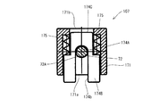
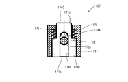
位置調整手段7は、案内溝61aの側面61C側端部を覆う支持部材71と、支持部材71に対して回転可能に支持される調整ねじ72と、調整ねじ72の回転に伴い支持部材71内を上下動する移動部材73と、調整ねじ72を上方に付勢するばね74とを有している。
The position adjusting means 7 includes a
支持部材71は、略箱形状であって、案内溝61aの延びる方向に延び案内溝61aと連通する貫通孔71aを有している。貫通孔71aは、棒部材62Fの外径よりも大きい径を有している。支持部材71の上面71Aには、後述の調整ねじ72の雄ねじ部72Aの径よりも略大きい径の貫通孔71bが形成されている。支持部材71の上面71Aにはばね74の一端が固定されている。
The
調整ねじ72は、雄ねじ部72Aと、雄ねじ部72Aに接続され一体的に回転する操作部72Bと、調整ねじ72の移動可能範囲を規制する規制手段72Cとを有している。具体的には、規制手段72Cは、支持部材71及びばね74と共に、雄ねじ部72Aと後述の移動部材73の雌ねじ部73Aとの螺合が外れない位置に調整ねじ72を保持している。
The
移動部材73は、支持部材71に対して回転不能であって上下方向に移動可能に収容されている。移動部材73には、棒部材62Fの外径よりも僅かに大きい径を有する貫通孔73aが形成されている。移動部材73は雄ねじ部72Aに螺合可能な雌ねじ部73Aを有し、雌ねじ部73Aによって規定される雄ねじ部72Aの収容空間は貫通孔73aに連通されている。
The moving
固定手段8は、案内溝61aの反側面61C側を覆う支持部材81と、支持部材81に対して回転可能に支持される固定ねじ82と、固定ねじ82を支持部材81に対して付勢するばね83を有している。支持部材81には、支持部材71に形成される貫通孔71aと対向し、同方向に延び、略同じ大きさの径を有する貫通孔81aが形成されている。また、支持部材81は後述の固定ねじ82の雄ねじ部82Aに螺合可能な雌ねじ部81Aを有し、雌ねじ部81Aによって規定される雄ねじ部82Aの収容空間は貫通孔81aに連通されている。固定ねじ82は、雄ねじ部82Aと、雄ねじ部82Aに接続され一体的に回転する操作部82Bとを有している。ばね83は、一端を支持部材81の上端部に固定され、他端を操作部82Bに固定されている。
The fixing means 8 includes a
次に、主ベース61に対する補助ベース62の装着について説明する。まず、補助ベース62の前側の棒部材62Fを貫通孔71a、73a、案内溝61a、貫通孔81aに挿通して案内溝61a内の所定の位置に配置すると同時に、後側の棒部材62Fを案内溝61aに挿通して案内溝61a内の所定の位置に配置する。この状態で固定ねじ82の操作部82Bをばね83の付勢力に抗して回転させる。操作部82Bの回転に伴い雄ねじ部82Aが雌ねじ部81Aに螺合しながら降下するので、雄ねじ部82Aの下端によって棒部材62Fを案内溝61aの溝底に押圧して、補助ベース62を主ベース61に対して移動不能に固定する。具体的には、補助ベース62を主ベース61に対して移動不能に固定する程度に、主ベース61に対する補助ベース62の装着方向(幅方向)における所望の位置において棒部材62Fを締付ける。次に、位置調整手段7の操作部72Bを回転させると、雄ねじ部72Aと雌ねじ部73Aが螺合しているので、移動部材73と調整ねじ72とは相対的に移動する。このとき、移動部材73は支持部材71に対して回転不能に支持されており、かつ、調整ねじ72は規制手段72Cとばね74とによって上下方向における位置が保持されているので、移動部材73が上下方向に移動する。移動部材73が上下方向に移動することにより、貫通孔73a内に配置される棒部材62Fも一体的に上下動する。このようにして、作業者は、操作部72Bを回転させることにより、移動部材73を上下動させて微調整を行いながら、補助ベース62の底面62Cと主ベース61の底面61Bとを任意の位置に設定することができる。
Next, attachment of the
このような構成によれば、主ベース61の第1当接面である底面61Bに交差する方向の1つである上下方向における補助ベース62の第2当接面である底面62Cの位置を調整して、底面61Bと底面62Cとを面一にすることができるので、がたつきのない安定した状態で被切断部材を切断することができ、作業性の良い携帯用切断機を提供することができる。
According to such a configuration, the position of the
また、作業者は、位置調整手段7によって底面61Bと底面62Cとの位置を調整するとともに、固定手段8によって所望の位置において補助ベース62を主ベース61に対して移動不能に固定することができる。よって、安定して切断作業を行うことができる。
Further, the operator can adjust the positions of the
また、位置調整手段7及び固定手段8が、丸のこ刃3が被切断部材を切断していく切断進行方向において丸のこ刃3よりも前方に設けられているので、底面61B及び底面62Cのうち前端部のみを被切断部材に乗せて切断作業を行う場合にも安定した切断動作を行うことができる。
Further, since the position adjusting means 7 and the fixing means 8 are provided in front of the
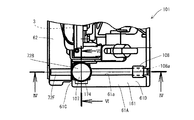
次に、図3乃至図10を参照して、本発明による第2の実施の形態に係る携帯用切断機である丸のこ101について説明する。第1の実施の形態に係る丸のこ1は、底面61Bと上下方向における底面62Cの位置を調整する位置調整手段7と、主ベース61の幅方向における所望の位置で補助ベース62を主ベース61に対して移動不能に固定する固定手段8とを別体として設ける構成であったが、第2の実施の形態に係る丸のこ101は、位置調整手段7及び固定手段8の両方の機能を兼ねる位置調整固定手段107を備えている。以下、第2の実施の形態について、第1の実施の形態と同一の部材について同一の符号を付しその説明を省略する。
Next, with reference to FIG. 3 thru | or FIG. 10, the
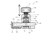
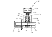
図3乃至図10に示されるように、丸のこ101は主ベース61に代えて主ベース161を備えている。主ベース161は、案内部61D(図3)において位置調整手段7に代えて位置調整固定手段107を有し、固定手段8に代えて抑え板108を有している。抑え板108は、案内溝61aの反側面61C側を覆うように設けられた略コ字型の板材であって、案内部61Dと共に棒部材62Fの外形よりも僅かに大きい貫通孔108aを形成している。
As shown in FIGS. 3 to 10, the
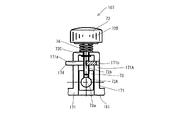
位置調整固定手段107は、案内溝61aの側面61C側端部を覆う支持部材171と、支持部材171に対して回転可能に支持される調整ねじ72と、調整ねじ72の回転に伴い支持部材171内を上下動可能な移動部材73と、調整ねじ72と螺合可能な雌ねじ部174A(図7、図9)を有する切替部材174と、切替部材174を一定の付勢力で付勢するばね175(図7、図9)とを有している。
The position adjustment fixing means 107 includes a
支持部材171は、支持部材71の構成に加え、前端部及び後端部に開口171a、171b(図6、図7、図9)が形成され切替部材174を前後方向に摺動可能に支持する切替部材支持部171Aを有している。切替部材174は、図7に示されるように、長手方向の長さが支持部材171の外形の前後方向の長さよりも長く、幅方向の長さが支持部材171の内周の幅方向の長さと略同じ板状であって、前端部174Bの幅方向中央部には長孔174bが形成され、後端部171Cの幅方向両端部が切欠かれた形状を有している。切替部材174の幅方向及び長手方向中央付近には、調整ねじ72の雄ねじ部72Aと螺合可能な雌ねじ部174Aが設けられている。前端部174Bの長孔171aは、雌ねじ部174Aによって規定される雄ねじ部72Aを配置可能な空間に連通している。
In addition to the structure of the
切替部材174は、ばね175によって支持部材171の後方から前方へ付勢されており、ばね175の自然状態において支持部材171の開口171aから前端部174Bが突出している。以下、雌ねじ部174Aと雄ねじ部72Aとが螺合している状態を螺合状態、螺合状態の切替部材174の位置を第1の位置と呼ぶ。
The switching
次に、主ベース161に対する補助ベース62の装着について説明する。まず、補助ベース62の前側の棒部材62Fを貫通孔71a、73a、案内溝61a、貫通孔108aに挿通して案内溝61a内の所定の位置に配置すると同時に、後側の棒部材62Fを案内溝61aに挿通して案内溝61a内の所定の位置に配置する。このとき図3乃至図8に示されるように切替部材174が第1の位置にあり、この状態において操作部72Bをばね74の付勢力に抗して回転させる。操作部74Bの回転に伴い、雄ねじ部72Aが切替部材174の雌ねじ部174Aに螺合しながら降下するので、雄ねじ部72Aの下端によって棒部材62Fを移動部材73に押圧して、補助ベース62を主ベース161に対して移動不能に固定する。具体的には、補助ベース62を主ベース161に対して移動不能に固定する程度に、主ベース161に対する補助ベース62の装着方向(幅方向)における所望の位置において棒部材62Fを締付ける。図8に示されるように、貫通孔73a内に配置された棒部材62Fまで調整ねじ72を移動させることにより、棒部材62Fは調整ねじ72によって移動部材73に向けて押圧されて、補助ベース62の幅方向において主ベース161に対して移動不能に固定される。なお、調整ねじ72は、雄ねじ部72Aが雌ねじ部73Aに螺合しながら移動部材73に対して相対的に移動する。具体的には、調整ねじ72が下方に移動するので、移動部材73は移動しない。調整ねじ72は、雌ねじ部73Aによって規定された空間から下方に突出し、棒部材62Fを移動部材73に対して締付けることができる。
Next, attachment of the
また、図9及び図10に示されるように、切替部材174をばね175の付勢力に抗して前方から後方に向けて押込むと、切替部材174の雌ねじ部174Aと調整ねじ72の雄ねじ部72Aとの螺合が解除される。以下、雌ねじ部174Aと雄ねじ部72Aとの螺合が解除された状態を解除状態と呼び、解除状態における切替部材174の位置を第2の位置と呼ぶ。切替部材174が第2の位置にある場合には、第1の実施の形態に係る丸のこ1と同様に、操作部72Bを回転させると、雄ねじ部72Aと移動部材73の雌ねじ部73Aとが螺合していることにより、移動部材73が調整ねじ72に対して相対的に移動する。調整ねじ72はばね74と切替部材174とにより上下方向に移動不能に支持部材171に保持されているので、移動部材73が上下方向に移動する。例えば、図8に示される状態から切替部材174を第1の位置(図7)から第2の位置(図9)に押込み、操作部72Bを回転させると、図10に示されるように調整ねじ72Bと移動部材73とは互いに離間する方向に移動し、換言すれば、移動部材73は下方に向かって移動する。そして、補助ベース62の底面62Cを上下方向における所望の位置に設定した後、切替部材174を開放するとばね175の戻り力によって切替部材174が第1の位置に戻り、切替部材174の雌ねじ部174Aと調整ねじ72の雄ねじ部72Aとが再度螺合する。この状態で操作部72Bを回転させることにより、棒部材62Fを所望の位置において主ベース161に対して移動不能に固定することができる。
9 and 10, when the switching
上述の丸のこ101によれば、補助ベース62の底面62Cの位置調整と主ベース161への固定との両方を同一の位置調整固定手段107によって行うので、操作性の良い携帯用切断機を実現することができる。また、装置全体の大型化を抑制することができる。
According to the
本発明に係る携帯用切断機は、上述の実施の形態に限定されず、特許請求の範囲に記載された範囲で種々の変形や改良が可能である。例えば、切断方向における後端部側の案内溝61a近傍にも、位置調整手段7、固定手段8、位置調整固定手段107を設けても良い。複数の位置調整手段7及び固定手段8を設けることにより、主ベース61の底面61Bに対する補助ベース62の底面62Cの位置決めをより精度よく行うことができる。
The portable cutting machine according to the present invention is not limited to the above-described embodiment, and various modifications and improvements can be made within the scope described in the claims. For example, the position adjusting means 7, the fixing means 8, and the position adjusting and fixing means 107 may be provided in the vicinity of the
上述の実施の形態では、固定手段8及び位置調整固定手段107によって棒部材72Fの固定(仮締め)を行ってから位置調整手段7及び位置調整固定手段107によって棒部材72Fの位置を調整する手順を説明したが、仮締めを省略して、位置調整を行った後に棒部材72Fを固定してもよい。
In the above-described embodiment, the
また、上述の実施の形態では、調整手段7及び位置調整固定手段107によって、上下方向(底面61Bに略直交する方向)における底面61Bに対する底面62Cの位置を調整可能な構成を示したが、本発明はこれに限られず、底面61Bに対して交差する方向における底面62Cの位置を調整する構成についても適宜応用することができる。
In the above-described embodiment, the configuration in which the position of the
また、棒部材72Fを主ベース61、161側に設け、案内部61D、位置調整手段7、固定手段8、位置調整固定手段107を補助ベース62に設けてもよい。
Further, the
1・・・丸のこ、2・・・ハウジング、3・・・丸のこ刃、4・・・ソーカバー、5・・・モータ、6・・・ベース部、7・・・位置調整手段、8・・・固定手段、21・・・収容部、21・・・反収容部、22・・・ハンドル、61・・・主ベース、61A・・・上面、61B・・・底面、61C・・・側面、61D・・・案内部、61a・・・案内溝、62・・・補助ベース、62A・・・底部、62B・・・側壁、62C・・・底面、62D・・・前端部、62E・・・後端部、62F・・・棒部材、71・・・支持部材、71A・・・上面、71a・・・貫通孔、71b・・・貫通孔、72A・・・雄ねじ部、72B・・・操作部、72C・・・規制手段、73・・・移動部材、73A・・・雌ねじ部、73a・・・貫通孔、81・・・支持部材、81A・・・雄ねじ部、81a・・・貫通孔、82B・・・操作部、107・・・位置調整固定手段、108・・・抑え板、108a・・・貫通孔、161・・・主ベース、171・・・支持部材、171A・・・切替部材支持部、171C・・・後端部、171a・・・開口、174・・・切替部材、174A・・・後端部、174B・・・前端部、174b・・・長孔
DESCRIPTION OF SYMBOLS 1 ... Circular saw, 2 ... Housing, 3 ... Circular saw blade, 4 ... Saw cover, 5 ... Motor, 6 ... Base part, 7 ... Position adjustment means, 8 ... fixing means, 21 ... accommodating portion, 21 ... anti-accommodating portion, 22 ... handle, 61 ... main base, 61A ... upper surface, 61B ... bottom surface, 61C ... Side surface, 61D: guide portion, 61a ... guide groove, 62 ... auxiliary base, 62A ... bottom, 62B ... side wall, 62C ... bottom surface, 62D ... front end, 62E ... rear end, 62F ... rod member, 71 ... support member, 71A ... upper surface, 71a ... through hole, 71b ... through hole, 72A ... male screw part, 72B ..Operating part, 72C ... regulating means, 73 ... moving member, 73A ... internal thread part, 73a ... through hole, 81 Support member, 81A ... male screw part, 81a ... through hole, 82B ... operation part, 107 ... position adjustment fixing means, 108 ... restraining plate, 108a ... through hole, 161 ... ..Main base, 171... Support member, 171A... Switching member support, 171C .. rear end, 171a .. opening, 174 .. switching member, 174A. 174B ... Front end, 174b ... Long hole
Claims (5)
該モータにより駆動されて被切断部材を切断する切断刃と、
該ハウジングに接続され、該被切断部材に当接する第1当接面を有し、該第1当接面から該切断刃を突出させる開口部が形成される主ベースと、
該主ベースに着脱可能に設けられ、該切断刃に対して該主ベースの反対側に設けられ、該第1当接面と共に該被切断部材に当接可能な第2当接面を有する補助ベースと、
該第1当接面に交差する方向における該第2当接面の位置を調整する位置調整機構と、を備えることを特徴とする携帯用切断機。 A housing that holds the motor;
A cutting blade driven by the motor to cut the member to be cut;
A main base that is connected to the housing and has a first abutting surface that abuts against the member to be cut, and an opening that projects the cutting blade from the first abutting surface;
Auxiliary provided on the main base in a detachable manner, provided on the opposite side of the main base with respect to the cutting blade, and having a second contact surface capable of contacting the member to be cut together with the first contact surface Base and
A portable cutting machine comprising: a position adjustment mechanism that adjusts a position of the second contact surface in a direction intersecting the first contact surface.
該第1当接面に略直交する方向における該第2当接面の位置を調整する位置調整手段と、
該主ベースに対する該補助ベースの装着方向における所望の位置において、該補助ベースを該主ベースに対して移動不能に固定する固定手段を備えることを特徴とする請求項1に記載の携帯用切断機。 The position adjusting mechanism is
Position adjusting means for adjusting the position of the second contact surface in a direction substantially perpendicular to the first contact surface;
The portable cutting machine according to claim 1, further comprising fixing means for fixing the auxiliary base to the main base so as to be immovable at a desired position in the mounting direction of the auxiliary base with respect to the main base. .
Priority Applications (1)
| Application Number | Priority Date | Filing Date | Title |
|---|---|---|---|
| JP2010266461A JP2012116048A (en) | 2010-11-30 | 2010-11-30 | Portable cutter |
Applications Claiming Priority (1)
| Application Number | Priority Date | Filing Date | Title |
|---|---|---|---|
| JP2010266461A JP2012116048A (en) | 2010-11-30 | 2010-11-30 | Portable cutter |
Publications (1)
| Publication Number | Publication Date |
|---|---|
| JP2012116048A true JP2012116048A (en) | 2012-06-21 |
Family
ID=46499500
Family Applications (1)
| Application Number | Title | Priority Date | Filing Date |
|---|---|---|---|
| JP2010266461A Pending JP2012116048A (en) | 2010-11-30 | 2010-11-30 | Portable cutter |
Country Status (1)
| Country | Link |
|---|---|
| JP (1) | JP2012116048A (en) |
Cited By (4)
| Publication number | Priority date | Publication date | Assignee | Title |
|---|---|---|---|---|
| JP2013144334A (en) * | 2012-01-13 | 2013-07-25 | Makita Corp | Cutting tool |
| JP2015074045A (en) * | 2013-10-08 | 2015-04-20 | リョービ株式会社 | Electric power cutting tool |
| JP2020116695A (en) * | 2019-01-24 | 2020-08-06 | 株式会社マキタ | Portable cutting machine |
| WO2021010136A1 (en) * | 2019-07-12 | 2021-01-21 | 工機ホールディングス株式会社 | Power tool |
Citations (2)
| Publication number | Priority date | Publication date | Assignee | Title |
|---|---|---|---|---|
| JP2004188738A (en) * | 2002-12-10 | 2004-07-08 | Makita Corp | Cutting tool |
| US20080295345A1 (en) * | 2007-05-31 | 2008-12-04 | Chervon Limited | Portable circular saw |
-
2010
- 2010-11-30 JP JP2010266461A patent/JP2012116048A/en active Pending
Patent Citations (2)
| Publication number | Priority date | Publication date | Assignee | Title |
|---|---|---|---|---|
| JP2004188738A (en) * | 2002-12-10 | 2004-07-08 | Makita Corp | Cutting tool |
| US20080295345A1 (en) * | 2007-05-31 | 2008-12-04 | Chervon Limited | Portable circular saw |
Cited By (8)
| Publication number | Priority date | Publication date | Assignee | Title |
|---|---|---|---|---|
| JP2013144334A (en) * | 2012-01-13 | 2013-07-25 | Makita Corp | Cutting tool |
| JP2015074045A (en) * | 2013-10-08 | 2015-04-20 | リョービ株式会社 | Electric power cutting tool |
| JP2020116695A (en) * | 2019-01-24 | 2020-08-06 | 株式会社マキタ | Portable cutting machine |
| JP7278786B2 (en) | 2019-01-24 | 2023-05-22 | 株式会社マキタ | portable cutting machine |
| WO2021010136A1 (en) * | 2019-07-12 | 2021-01-21 | 工機ホールディングス株式会社 | Power tool |
| JPWO2021010136A1 (en) * | 2019-07-12 | 2021-01-21 | ||
| CN114080289A (en) * | 2019-07-12 | 2022-02-22 | 工机控股株式会社 | Power tool |
| JP7074261B2 (en) | 2019-07-12 | 2022-05-24 | 工機ホールディングス株式会社 | Power tools |
Similar Documents
| Publication | Publication Date | Title |
|---|---|---|
| EP3261794B1 (en) | Miter saw | |
| US6647847B2 (en) | Fence | |
| JP4600184B2 (en) | Guide and portable cutting tool provided with the same | |
| JP4552873B2 (en) | Tabletop cutting machine | |
| US7963043B2 (en) | Support shoe for a reciprocating saw | |
| AU2002240365A1 (en) | Fence with a fine adjustment mechanism | |
| EP1880786A2 (en) | Vise mechanism incorporated in cutting machine | |
| JP2012194465A (en) | Optical fiber cutter | |
| US8151676B2 (en) | Structures for supporting splitters of cutting tools | |
| US20140174273A1 (en) | Rip fence having dual adjustment for a power tool | |
| WO2013013607A1 (en) | Cutting machine | |
| JP2012116048A (en) | Portable cutter | |
| US9533361B2 (en) | Cutting machines | |
| JP2010005750A (en) | Desktop cutter | |
| US6260460B1 (en) | Machining tools having adjustable fences | |
| JP7103002B2 (en) | Cutting machine | |
| JP2009083333A (en) | Bench cutting machine | |
| JP2010274390A (en) | Bench cutter | |
| JP2015221540A (en) | Cutting machine | |
| JP2019005920A (en) | Adapter for ruler | |
| JP5526091B2 (en) | Machining aids in machining operations | |
| JP2010201882A (en) | Portable cutter | |
| US20140331840A1 (en) | Cutting machine | |
| JP2010076059A (en) | Portable cutting machine | |
| JP5741120B2 (en) | Portable cutting machine |
Legal Events
| Date | Code | Title | Description |
|---|---|---|---|
| A621 | Written request for application examination |
Free format text: JAPANESE INTERMEDIATE CODE: A621 Effective date: 20131108 |
|
| A02 | Decision of refusal |
Free format text: JAPANESE INTERMEDIATE CODE: A02 Effective date: 20150305 |