JP4552873B2 - Tabletop cutting machine - Google Patents
Tabletop cutting machine Download PDFInfo
- Publication number
- JP4552873B2 JP4552873B2 JP2006062627A JP2006062627A JP4552873B2 JP 4552873 B2 JP4552873 B2 JP 4552873B2 JP 2006062627 A JP2006062627 A JP 2006062627A JP 2006062627 A JP2006062627 A JP 2006062627A JP 4552873 B2 JP4552873 B2 JP 4552873B2
- Authority
- JP
- Japan
- Prior art keywords
- base
- turntable
- tip
- cutting machine
- support
- Prior art date
- Legal status (The legal status is an assumption and is not a legal conclusion. Google has not performed a legal analysis and makes no representation as to the accuracy of the status listed.)
- Active
Links
Images


Classifications
-
- B—PERFORMING OPERATIONS; TRANSPORTING
- B27—WORKING OR PRESERVING WOOD OR SIMILAR MATERIAL; NAILING OR STAPLING MACHINES IN GENERAL
- B27B—SAWS FOR WOOD OR SIMILAR MATERIAL; COMPONENTS OR ACCESSORIES THEREFOR
- B27B5/00—Sawing machines working with circular or cylindrical saw blades; Components or equipment therefor
- B27B5/29—Details; Component parts; Accessories
-
- B—PERFORMING OPERATIONS; TRANSPORTING
- B23—MACHINE TOOLS; METAL-WORKING NOT OTHERWISE PROVIDED FOR
- B23D—PLANING; SLOTTING; SHEARING; BROACHING; SAWING; FILING; SCRAPING; LIKE OPERATIONS FOR WORKING METAL BY REMOVING MATERIAL, NOT OTHERWISE PROVIDED FOR
- B23D45/00—Sawing machines or sawing devices with circular saw blades or with friction saw discs
- B23D45/04—Sawing machines or sawing devices with circular saw blades or with friction saw discs with a circular saw blade or the stock carried by a pivoted lever
- B23D45/042—Sawing machines or sawing devices with circular saw blades or with friction saw discs with a circular saw blade or the stock carried by a pivoted lever with the saw blade carried by a pivoted lever
- B23D45/046—Sawing machines or sawing devices with circular saw blades or with friction saw discs with a circular saw blade or the stock carried by a pivoted lever with the saw blade carried by a pivoted lever the pivoted lever being mounted on a carriage
- B23D45/048—Sawing machines or sawing devices with circular saw blades or with friction saw discs with a circular saw blade or the stock carried by a pivoted lever with the saw blade carried by a pivoted lever the pivoted lever being mounted on a carriage the saw blade being adjustable according to angle of cut
-
- B—PERFORMING OPERATIONS; TRANSPORTING
- B23—MACHINE TOOLS; METAL-WORKING NOT OTHERWISE PROVIDED FOR
- B23D—PLANING; SLOTTING; SHEARING; BROACHING; SAWING; FILING; SCRAPING; LIKE OPERATIONS FOR WORKING METAL BY REMOVING MATERIAL, NOT OTHERWISE PROVIDED FOR
- B23D47/00—Sawing machines or sawing devices working with circular saw blades, characterised only by constructional features of particular parts
- B23D47/02—Sawing machines or sawing devices working with circular saw blades, characterised only by constructional features of particular parts of frames; of guiding arrangements for work-table or saw-carrier
- B23D47/025—Sawing machines or sawing devices working with circular saw blades, characterised only by constructional features of particular parts of frames; of guiding arrangements for work-table or saw-carrier of tables
-
- Y—GENERAL TAGGING OF NEW TECHNOLOGICAL DEVELOPMENTS; GENERAL TAGGING OF CROSS-SECTIONAL TECHNOLOGIES SPANNING OVER SEVERAL SECTIONS OF THE IPC; TECHNICAL SUBJECTS COVERED BY FORMER USPC CROSS-REFERENCE ART COLLECTIONS [XRACs] AND DIGESTS
- Y10—TECHNICAL SUBJECTS COVERED BY FORMER USPC
- Y10T—TECHNICAL SUBJECTS COVERED BY FORMER US CLASSIFICATION
- Y10T83/00—Cutting
- Y10T83/768—Rotatable disc tool pair or tool and carrier
- Y10T83/7684—With means to support work relative to tool[s]
- Y10T83/7693—Tool moved relative to work-support during cutting
- Y10T83/7697—Tool angularly adjustable relative to work-support
-
- Y—GENERAL TAGGING OF NEW TECHNOLOGICAL DEVELOPMENTS; GENERAL TAGGING OF CROSS-SECTIONAL TECHNOLOGIES SPANNING OVER SEVERAL SECTIONS OF THE IPC; TECHNICAL SUBJECTS COVERED BY FORMER USPC CROSS-REFERENCE ART COLLECTIONS [XRACs] AND DIGESTS
- Y10—TECHNICAL SUBJECTS COVERED BY FORMER USPC
- Y10T—TECHNICAL SUBJECTS COVERED BY FORMER US CLASSIFICATION
- Y10T83/00—Cutting
- Y10T83/768—Rotatable disc tool pair or tool and carrier
- Y10T83/7684—With means to support work relative to tool[s]
- Y10T83/7701—Supporting surface and tool axis angularly related
- Y10T83/7705—Adjustable angular relationship
-
- Y—GENERAL TAGGING OF NEW TECHNOLOGICAL DEVELOPMENTS; GENERAL TAGGING OF CROSS-SECTIONAL TECHNOLOGIES SPANNING OVER SEVERAL SECTIONS OF THE IPC; TECHNICAL SUBJECTS COVERED BY FORMER USPC CROSS-REFERENCE ART COLLECTIONS [XRACs] AND DIGESTS
- Y10—TECHNICAL SUBJECTS COVERED BY FORMER USPC
- Y10T—TECHNICAL SUBJECTS COVERED BY FORMER US CLASSIFICATION
- Y10T83/00—Cutting
- Y10T83/768—Rotatable disc tool pair or tool and carrier
- Y10T83/7684—With means to support work relative to tool[s]
- Y10T83/7722—Support and tool relatively adjustable
- Y10T83/7726—By movement of the tool
-
- Y—GENERAL TAGGING OF NEW TECHNOLOGICAL DEVELOPMENTS; GENERAL TAGGING OF CROSS-SECTIONAL TECHNOLOGIES SPANNING OVER SEVERAL SECTIONS OF THE IPC; TECHNICAL SUBJECTS COVERED BY FORMER USPC CROSS-REFERENCE ART COLLECTIONS [XRACs] AND DIGESTS
- Y10—TECHNICAL SUBJECTS COVERED BY FORMER USPC
- Y10T—TECHNICAL SUBJECTS COVERED BY FORMER US CLASSIFICATION
- Y10T83/00—Cutting
- Y10T83/768—Rotatable disc tool pair or tool and carrier
- Y10T83/7755—Carrier for rotatable tool movable during cutting
- Y10T83/7763—Tool carrier reciprocable rectilinearly
- Y10T83/7768—With means to adjust path of reciprocation
- Y10T83/7772—Angular relative to previous path
-
- Y—GENERAL TAGGING OF NEW TECHNOLOGICAL DEVELOPMENTS; GENERAL TAGGING OF CROSS-SECTIONAL TECHNOLOGIES SPANNING OVER SEVERAL SECTIONS OF THE IPC; TECHNICAL SUBJECTS COVERED BY FORMER USPC CROSS-REFERENCE ART COLLECTIONS [XRACs] AND DIGESTS
- Y10—TECHNICAL SUBJECTS COVERED BY FORMER USPC
- Y10T—TECHNICAL SUBJECTS COVERED BY FORMER US CLASSIFICATION
- Y10T83/00—Cutting
- Y10T83/768—Rotatable disc tool pair or tool and carrier
- Y10T83/7755—Carrier for rotatable tool movable during cutting
- Y10T83/7788—Tool carrier oscillated or rotated
-
- Y—GENERAL TAGGING OF NEW TECHNOLOGICAL DEVELOPMENTS; GENERAL TAGGING OF CROSS-SECTIONAL TECHNOLOGIES SPANNING OVER SEVERAL SECTIONS OF THE IPC; TECHNICAL SUBJECTS COVERED BY FORMER USPC CROSS-REFERENCE ART COLLECTIONS [XRACs] AND DIGESTS
- Y10—TECHNICAL SUBJECTS COVERED BY FORMER USPC
- Y10T—TECHNICAL SUBJECTS COVERED BY FORMER US CLASSIFICATION
- Y10T83/00—Cutting
- Y10T83/869—Means to drive or to guide tool
- Y10T83/8773—Bevel or miter cut
Landscapes
- Engineering & Computer Science (AREA)
- Mechanical Engineering (AREA)
- Life Sciences & Earth Sciences (AREA)
- Wood Science & Technology (AREA)
- Forests & Forestry (AREA)
- Sawing (AREA)
Description
本発明は卓上切断機に関し、特にターンテーブルを備えた卓上切断機に関する。 The present invention relates to a tabletop cutting machine, and more particularly to a tabletop cutting machine having a turntable.
従来の卓上切断機においては、ベース上に載置された被加工部材である木材等を任意の角度で切断するために、切断刃が保持される切断部をベースに対して回動可能なターンテーブルを設けている。 In a conventional tabletop cutting machine, in order to cut wood or the like that is a workpiece mounted on a base at an arbitrary angle, a turn that can rotate a cutting portion that holds a cutting blade with respect to the base There is a table.
このターンテーブルを回動させるべく、卓上切断機の前側(作業者側)位置には、ターンテーブルより突出する突出部が設けられ、この突出部にターンテーブル回動操作用のハンドルが設けられている(特許文献1参照)。
この卓上切断機は、一般に各所の作業現場に持ち運んで木材等を加工することが多いため、持ち運びが楽なように小型化が推し進められている。 In general, this tabletop cutting machine is often carried to work sites in various places to process wood and the like, and therefore, downsizing has been promoted for easy carrying.
しかし、従来の卓上切断機では、ハンドルが卓上切断機の前方から突出する構造を採っているために、移動時にハンドルが邪魔となって持ち運び難い場合があった。また卓上切断機を収納する際や梱包する際に、例えば段ボール箱等に詰める場合では、ハンドルが突出しているために、垂直投射面積が大きくなり、これに応じて不要に大きな包用の箱が必要となっていた。 However, the conventional tabletop cutting machine has a structure in which the handle protrudes from the front of the tabletop cutting machine, so that the handle may be difficult to carry when moving. Also, when storing or packing a tabletop cutting machine, for example, when packing in a cardboard box, the vertical projection area increases because the handle protrudes, and accordingly an unnecessarily large packaging box is formed. It was necessary.
そこで、本発明は小型化可能であり、かつ運搬を容易とした卓上切断機を提供することを目的とする。 Therefore, an object of the present invention is to provide a tabletop cutting machine that can be miniaturized and can be easily transported.
上記課題を解決するために本発明は、加工部材を支持するベースと、該ベース上に支持され該ベースに対して回動可能なターンテーブルと、該ターンテーブルに設けられ該ターンテーブルの上方で切断刃を揺動可能に支持する切断部と、該ベース及び該ターンテーブルに関連して該ターンテーブルを該ベースに対して回動不能に固定可能な固定機構と、を備え、該ターンテーブルは該切断刃が揺動して交わる箇所となるターンテーブル本体と、該ターンテーブル本体と該切断刃と該ターンテーブル本体とが交わる交線の延長線上にあって該ターンテーブル本体外周から該交線の延長線方向に突出する突出部とを有し、該ターンテーブル本体及び該突出部は該ベースと共に該加工部材を支持するように構成され、該突出部は該ターンテーブル本体外周からの突出量を変更可能である卓上切断機を提供する。 In order to solve the above problems, the present invention provides a base for supporting a processing member, a turntable supported on the base and rotatable with respect to the base, and provided on the turntable above the turntable. A cutting portion that swingably supports a cutting blade, and a fixing mechanism that can fix the turntable to the base in a non-rotatable manner in relation to the base and the turntable. The turntable body which is a place where the cutting blades oscillate and intersect, and the line of intersection from the outer periphery of the turntable body on an extension line of the intersection of the turntable body, the cutting blade and the turntable body and a protrusion protruding in the extension direction, the turntable body and projecting portion is configured to support the workpiece with the base, projecting portion is present the turntable Providing miter saw can change the amount of projection of the outer periphery.
上記卓上切断機において該突出部は該ターンテーブル本体と一体に設けられた基部と、該基部の先端側に位置して該基部に支持される先端部とを備え、該突出部の突出量変化は該基部に対する該先端部の位置変化により達成されることが好ましい。 In the tabletop cutting machine, the protrusion includes a base provided integrally with the turntable body, and a tip positioned on the tip of the base and supported by the base, and the protrusion amount change of the protrusion Is preferably achieved by a change in the position of the tip relative to the base.
また該先端部は該基部に対して移動不能に固定された支持位置と、該基部への固定が解除された非支持位置との間で移動可能であることが好ましい。 The tip portion includes a support position that is immovably fixed against the base portion, it is preferable secured to the base portion is movable between an unsupported position is released.
また該基部は、該交線の延長方向と略直交する方向に延びる回動軸を備え、該先端部は、該基部の延出方向と該先端部の延出方向とが同一となる該支持位置と該基部の延出方向と該先端部の延出方向とが略直交する非支持位置との間を回動可能に回動軸で軸支されていてもよく、該先端部と該基部とに関連して、該先端部が支持位置及び非支持位置にある状態で該基部に対する該先端部の位置を固定する位置固定機構が設けられていてもよい。 The base portion includes a rotation shaft extending in a direction substantially orthogonal to the extending direction of the intersecting line, and the tip portion has the support direction in which the extension direction of the base portion and the extension direction of the tip portion are the same. The distal end portion and the base portion may be pivotally supported by a pivot shaft so as to be rotatable between a position, an extending direction of the base portion, and an unsupported position where the extending direction of the distal end portion is substantially orthogonal to each other. A position fixing mechanism for fixing the position of the tip portion with respect to the base portion in a state where the tip portion is in the support position and the non-support position may be provided.
また該基部は該加工部材と対向する基部上面を有し、該回動軸は該基部上面近傍に該基部上面と該回動軸の軸方向が略平行になるように設けられ、該先端部が該支持位置にある状態で該基部と該先端部との互いに対面する位置には、該先端部の該基部に対する回動角度を調整する回動角度調整機構が設けられていてもよい。 The base has a base upper surface facing the processing member, and the pivot shaft is provided in the vicinity of the base upper surface so that the axial direction of the base upper surface and the pivot shaft is substantially parallel to the tip. A rotation angle adjusting mechanism that adjusts the rotation angle of the tip portion with respect to the base portion may be provided at a position where the base portion and the tip portion face each other in a state where the tip portion is in the support position.
また該先端部は該基部に着脱可能に設けられ、該先端部が該基部に装着された状態で該先端部は該支持位置にあり、該先端部が該基部から離脱した状態で該先端部は非支持位置にあってもよい。 The tip is detachably provided on the base, the tip is in the support position with the tip attached to the base, and the tip is detached from the base. May be in an unsupported position.
また該先端部と該基部とは、該先端部が該基部に隣接する位置と該基部に離間する位置との間で該交線方向において移動可能に構成されていてもよい。 Further, the distal end portion and the base portion may be configured to be movable in the intersecting direction between a position where the distal end portion is adjacent to the base portion and a position where the distal end portion is separated from the base portion.
また該ベースの該ターンテーブルの回動軸を中心とする円弧位置に複数設けられた係止部と、該基部に設けられて該係止部と係合可能であると共に該係止部に対する係合・離脱を選択的に操作可能な係合部材と、を備えることが好ましい。 Also, a plurality of locking portions provided at a circular arc position around the rotation axis of the turntable of the base, and provided on the base portion and engageable with the locking portions, and are engaged with the locking portions. It is preferable to include an engaging member capable of selectively operating the combination / detachment.
また該切断部は、該切断刃を該交線と平行に移動可能な移動機構を備えることが好ましく、特に該切断部は、切断刃を回転可能に支持する切断本体部と、該ターンテーブルに支持されると共に該切断本体部を支持する支持部と、を備え、該支持部は、該切断本体部を揺動可能に支持する揺動支持部と、該ターンテーブルの回動中心に対して該突出部の反対位置に設けられ該揺動支持部を保持すると共に該交線と略平行な方向に該揺動支持部を移動可能とするスライド支持部と、を有し、該移動機構は、該揺動支持部と該スライド支持部から構成されることが好ましい。 The cutting unit preferably includes a moving mechanism capable of moving the cutting blade in parallel with the line of intersection. In particular, the cutting unit includes a cutting main body that rotatably supports the cutting blade, and the turntable. A support portion that is supported and supports the cutting body portion, the support portion supporting the swinging body portion so as to be swingable, and a rotation center of the turntable. A slide support portion provided at a position opposite to the projecting portion and configured to hold the swing support portion and to move the swing support portion in a direction substantially parallel to the intersecting line. The swing support part and the slide support part are preferably used.
請求項1及び請求項2記載の卓上切断機によれば、突出部の突出量を変化することができるため、卓上切断機の鉛直投影面積を小さくすることができる。従って、卓上切断機を梱包する際にもその梱包後の大きさを小さくすることができ、輸送時の利便性を向上させることができる。また突出量を小さくすることにより、出っ張り部分が小さくなる。従って卓上切断機を移動する際にも邪魔にならず、好適に移動することができる。 According to the tabletop cutting machine of Claim 1 and Claim 2, since the protrusion amount of a protrusion part can be changed, the vertical projection area of a tabletop cutting machine can be made small. Therefore, when packing a tabletop cutting machine, the size after packing can be reduced, and convenience during transportation can be improved. Further, by reducing the protruding amount, the protruding portion is reduced. Therefore, when moving a tabletop cutting machine, it is possible to move it without disturbing it.
請求項3記載の卓上切断機に寄れば先端部が加工部材を支持できる位置にあるため、ベースと協働してより大きな加工部材が載置されて切断することができる。
If it approaches the desktop cutting machine of
請求項4、請求項7及び請求項8記載の卓上切断機によれば、突出部において先端部が折り曲げられる形状となるか、突出部において先端部が取り外されるか、若しくは突出部において先端部が突出方向に移動するため、突出部の突出量が変化する。従ってこれらの構成により、請求項1の効果を得ることができる。
According to the tabletop cutting machine according to
請求項6記載の卓上切断機によれば、支持位置において先端部の基部に対する回動角度を調整することができる。よって先端部に加工部材を載置する際に、回動角度調整機構により加工部材が載置される先端部の上面と、基部の上面とを略平行になるように調整することができる。 According to the tabletop cutting machine of the sixth aspect, the rotation angle of the tip portion with respect to the base portion can be adjusted at the support position. Therefore, when the processing member is placed on the tip portion, the upper surface of the tip portion on which the processing member is placed and the upper surface of the base portion can be adjusted to be substantially parallel by the rotation angle adjusting mechanism.
請求項5記載の卓上切断機によれば、支持位置、非支持位置にある先端部の位置を固定するため、先端部が不要に動くことが抑制される。従って、卓上切断機を移動する際等の移送性を向上させることができる。 According to the tabletop cutting machine of the fifth aspect, since the position of the tip portion at the support position and the non-support position is fixed, it is possible to suppress the tip portion from moving unnecessarily. Accordingly, it is possible to improve transportability when moving the tabletop cutting machine.
請求項9記載の卓上切断機によれば、予め定めた任意の角度毎に係止部を形成しておくことにより、ターンテーブルの回動角度を容易に設定することができる。また設定と同時に回動不能にすることができるので、作業性を向上させることができる。 According to the tabletop cutting machine of the ninth aspect, the rotation angle of the turntable can be easily set by forming the locking portion at every predetermined angle. Further, since the rotation can be disabled simultaneously with the setting, workability can be improved.
請求項10及び請求項11記載の卓上切断機によれば、切断刃が摺動することにより、幅が広い加工部材を切断することができる。従って、従来2回に分けて切断していた加工部材を一回で切断することが可能となり、作業性を向上させることができる。
According to the tabletop cutting machine of
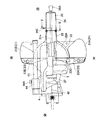
本発明の第一の実施の形態について、図1乃至図8に基づき説明する。図1に示される卓上切断機である卓上丸鋸1は、スライド機構を備えた卓上丸鋸であり、ベース部2と、切断部3とから主に構成されている。
A first embodiment of the present invention will be described with reference to FIGS. A tabletop saw 1 that is a tabletop cutting machine shown in FIG. 1 is a tabletop saw having a slide mechanism, and is mainly composed of a base portion 2 and a
ベース部2は、被切断部材である木材Wを担持するベース21と、ベース21上に回動可能に担持されたターンテーブル22と、ベース21に設けられたフェンス23とから主に構成されている。ベース21は、図2及び図3に示されるように、一対の左ベース21Aと右ベース21Bとから構成されている。これら左ベース21Aと右ベース21Bとが並んでいる方向を左右方向と定義し、ベース21の木材Wを載置する面の上方を上方、反対を下方と定義する。また図6に示されるように、ベース21(図1)においては、ターンテーブル22により覆われる箇所に、ターンテーブル22の回動中心となる中心軸22Cを中心とする円弧状に構成された規制部材21Cが設けられている。規制部材21Cには、係合部となる凹部21bが規制部材21Cの円周方向に区分する所定の角度毎に複数形成されている。
The base portion 2 is mainly composed of a
ターンテーブル22は、右ベース21Bと左ベース21Aとの間に配置されている。図1に示されるように、ターンテーブル22は、略円台状のターンテーブル本体部22Aとターンテーブル本体部22Aの一方側に突出する突出部24と他方側に設けられた後述の支持部4を支持する切断部支持部27とから構成されている。この突出部24がターンテーブルより突出している方向であって左右方向(図3)と直交する方向を前方、反対を後方と定義する。
The
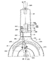
図3に示されるように、ターンテーブル22の上面には、切断部支持部27近傍位置から突出部24にかけて一連の溝部22aが形成されている。この溝部22aは、後述の丸鋸刃6が下方に揺動してターンテーブル22と交わった際の交線位置と同一位置にあり丸鋸刃6の刃先を収容する箇所となる。
As shown in FIG. 3, a series of
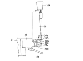
図1に示されるように、突出部24は、ターンテーブル本体部22Aと一体の基部25と、基部25に軸25Aで回動自在に支持された先端部26とから主に構成されている。軸25Aはその軸方向が、基部25のターンテーブル本体部22Aからの延出方向と略直交して基部25の上面とその軸方向が略平行になるように、基部25の先端位置であって基部25の上部位置に設けられている。基部25の下方側位置にはターンテーブル22のベース21に対する回動を規制する際の操作部となる規制操作部28(図1)と基部25の上面と略直交する平面を備えた壁である突き当て部25B(図5)が設けられている。
As shown in FIG. 1, the
図7に示されるように、規制操作部28は、側面形状が略L字形状を成す規制レバー28Aと軸部28Bと、後述の係止部29に規制レバー28Aでの動作を伝達する伝達部28Cとから構成されている。軸部28Bは、基部25にその軸が基部25の延出方向と略直交して左右方向に延びるように設けられ、規制レバー28Aを回動可能に支持している。規制レバー28Aは、第一腕部28Dと第二腕部28EとからL字状に構成され、第一腕部28Dと第二腕部28Eとの結合位置で軸部28Bに軸支されている。第一腕部28Dは、基部25の下方に延出されており、作業者により回動操作可能となっている。第二腕部28Eの端部には、伝達部28Cの一端が当接しており、第一腕部28Dが回動操作されることにより、伝達部28Cを付勢可能となっている。伝達部28Cは、基部25に基部25延出方向に移動可能に保持されて、第二腕部28Eによる動作をその他端側で係止部29に伝達可能となっている。
As shown in FIG. 7, the
また先端部26の基端位置であって下方側位置には、後述のピン26Cと択一的に係合可能な第一保持孔26aと第二保持孔26bとが形成された固定機構部26Bが設けられている。
Further, a
図6に示されるように、ターンテーブル22の内部であって、中心軸22C周辺位置には、係止部29が設けられている。係止部29は、フレーム29Aとスライド部29Bとバネ29Cとから主に構成されている。スライド部29Bとバネ29Cとは、フレーム29A内に収納されており、バネ29Cによりスライド部29Bはその軸方向に摺動可能となっている。スライド部29Bは、略凸状に形成されている凸部29Dと伝達部28Cと係合する当接部29Eと有している。スライド部29Bは当接部29Eが伝達部28Cにより付勢されることによって摺動することから、凸部29Dは、凹部21bと係合・離脱可能となっている。よって凸部29Dが凹部21bと係合している状態では、ターンテーブル22とベース21とは互いに回動不能となる。
As shown in FIG. 6, a locking
図1及び図7に示されるように、先端部26は、軸25Aにより軸支されており、軸25Aを支点として上方に回動することができる。図1に示されるように、先端部26の最先端部分には、ターンテーブル22を回動する際の把握箇所となるハンドル26Aが設けられている。また先端部26の基端側位置には、後述の支持位置において、突き当て部25Bと対向する位置にネジ部26Dが設けられている。これら突き当て部25Bとネジ部25Dから先端部26の回動角度を調整する回動角度調整機構が構成されている。
As shown in FIGS. 1 and 7, the
図2及び図5に示されるように、基部25の右側側面部分には、突出部24の延出方向と略直交する方向に移動可能なピン26Cが設けられている。このピン26Cは第一保持孔26aと第二保持孔26bとのいずれか一方に係合することが可能となっている。具体的には、図6及び図7に示されるように、突出部24の上面がターンテーブル本体部22Aの上面と同一面となり、基部25の突出方向と突出部24の突出方向が略同一となる位置(支持位置)においてピン26Cは、第二保持孔26bに挿入され、図8に示されるように、支持位置から回動されて突出部24の突出方向が基部25の突出方向と略直交する方向になる位置(非支持位置)においてピン26Cは、第一保持孔26aに挿入される。
As shown in FIGS. 2 and 5, a
図1に示されるように、切断部支持部27は、ターンテーブル22の中心軸22Cに対して突出部24の反対位置に配置されている。切断部支持部27には、溝部22a(図3)の延長線上に位置する傾動軸27Aと、切断部3が任意の傾斜角度で固定される傾動支持部27Bとを有している。
As shown in FIG. 1, the cutting
図1に示されるように、ベース21上であって、ターンテーブル22の上方位置には、フェンス23が設けられている。フェンス23は、図2及び図3に示されるように、左ベース21A及び右ベース21Bに対応して左フェンス23A及び右フェンス23Bから構成されており、左フェンス23A及び右フェンス23Bの前面は、同一平面状に位置するように配置されて、木材W(図1)の位置を規定している。また図2に示されるように、左フェンス23Aであってターンテーブル本体部22Aの上方となる位置には、固定ネジ23Cが螺合している。固定ネジ23Cは螺進することにより下側へ移動しターンテーブル本体部22Aと当接して、ターンテーブル22の回動を固定することが可能となっている。
As shown in FIG. 1, a
図1に示されるように、切断部3は、支持部4と切断本体部5とから主に構成されている。支持部4は、揺動支持部41と、スライド支持部42と、一対のスライドバー43と、スライド部44とから主に構成されている。スライド支持部42は、傾動軸27Aによりターンテーブル22に対して略左右方向に傾動可能に軸支されている。スライド支持部42の後端部位置には、傾動支持部27Bと協働して切断部3のターンテーブル22及びベース21に対する傾動角度を規定する傾動固定部42Aが設けられている。
As shown in FIG. 1, the cutting
一対のスライドバー43は、スライド支持部42の上方に上下方向に並んでその軸方向が溝部22a(図3)と略平行になるように前側に延出されて設けられている。スライド部44は、スライドバー43に摺動可能に設けられている。スライド部44の側面部分には、ネジ44Aが設けられており、スライド部44をスライドバー43の任意の位置で固定可能となっている。
The pair of slide bars 43 are arranged above the
スライド部44には揺動支持部41が一体に設けられている。揺動支持部41は上部に左右方向に並ぶ一対の腕部が形成されており、この一対の腕部に跨って切断本体部5を軸支する揺動軸41Aが設けられている。揺動軸41Aの周囲には、切断本体部5を揺動支持部41に対して上方に付勢するバネ41Bが設けられている。また揺動支持部41の前面位置には、木材W上に切断位置を示唆するレーザ光を発振するレーザ発振器45が設けられている。
The
図1に示されるように、切断本体部5は、ハウジング51と、モータ52と、ハンドル53と移動用ハンドル54と鋸刃カバー55とを備え、切断刃である丸鋸刃6を回転可能に支持している。ハウジング51は、その下端で揺動軸41Aに軸支され、バネ41Bで上方に付勢されている。モータ52は丸鋸刃6を駆動し、ハウジング51内に配置されている。ハンドル53はハウジング51の上部に設けられて、切断本体部5を揺動する際の把握箇所となる。またハンドル53にはモータ52の回転制御を行うスイッチ53Aが設けられている。移動用ハンドル54はモータ52近傍位置に設けられて、切断本体部5を図示せぬピンで最下方に揺動させた状態で、卓上丸鋸1を移動する際に把握する箇所となる。鋸刃カバー55はハウジング51と一体に設けられており、その内部に丸鋸刃6を備えて保護している。
As shown in FIG. 1, the cutting
上記構成の卓上丸鋸1で木材Wを切断する際には、先ず先端部26を支持位置に配置する。この際に先端部26の上面と基部25の上面とが略同一平面上に位置するように、ネジ部26Dを調節する。その後にピン26Cと固定機構部26Bとにより先端部26を基部25に回動不能に固定する。そして図1または図4に示されるように、木材Wをベース21上に載置して、ターンテーブル22の回動角度を調整する。この際に固定ネジ23Cを緩めておくと共に、規制レバー28Aを上方へ押し上げて凹部21bと凸部29Dとの係合を解除する。凸部29Dの凹部21bへの係合により決定される所定の角度若しくは凸部29Dと凹部21bとが非係合となる状態での角度に設定した後に、固定ネジ23Cを締めてターンテーブル22とベース21とを固定する。
When cutting the wood W with the tabletop circular saw 1 having the above-described configuration, first, the
木材Wの前後方向における幅が小さい場合には、図1に示されるように、スライド部44を最も後に下げた状態で、切断本体部5を下方に揺動して切断を行う。
When the width of the wood W in the front-rear direction is small, as shown in FIG. 1, the cutting
また図4に示されるように、木材Wの前後方向における幅が大きい場合には、切断本体部5を最も前方まで摺動させ、スイッチ53AをONにして丸鋸刃6を回転させながら、切断本体部5を下方に揺動した後に、丸鋸刃6を回転させた状態で切断本体部5を後方に移動させる。この場合に木材Wの前側部分は、突出部24上に担持されるため、安定して木材Wを切断することができる。
As shown in FIG. 4, when the width of the wood W in the front-rear direction is large, the cutting
切断が終了した後に、卓上丸鋸1を移動し、または片付ける場合には、切断本体部5を最も後に摺動すると共に、ピン26Cと第二保持孔26bの係合を解いて先端部26を図8に示すように上方へ回動させる。その後にピン26Cと第一保持孔26aとを係合させて先端部26が下方へ回動しないようにする。このようにすることにより、卓上丸鋸1の前後方向の幅が切断部支持部27の後端位置から基部25の略先端位置までの距離とすることができ、通常使用する状態よりコンパクトにすることができる。
When the table-like circular saw 1 is moved or put away after the cutting is finished, the cutting
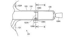
次に本発明の第二の実施の形態として図9乃至図12に基づき説明する。第二の実施の形態に係る卓上切断機である卓上丸鋸101では、突出部124に係る構成以外は第一の実施の形態に係る卓上丸鋸1の構成と同一であるため、その説明を省略する。また同一構成の部分では、第一の実施の形態に係る符号に100を足してその説明を省略する。
Next, a second embodiment of the present invention will be described with reference to FIGS. The
図9に示されるように突出部124は、ターンテーブル本体部122Aから延出される基部125と基部125の延出方向先端に位置する先端部126とから主に構成されている。図9及び図11に示されるように、先端部126の先端部分にはハンドル126Aが設けられており、先端部126と基部125との連結部分であって左側側面部分にはネジ126Bが設けられている。先端部126の基部125と対向する位置には、略鈎状を成す一対の腕部126C、126Cが設けられている。基部125の先端部126と対向する位置には、側面に一対の溝部を備えた係合部125Aが設けられており、図1に示されるように、係合部125Aと一対の腕部126C、126Cとが係合して基部125と先端部126とが連結されている。
As shown in FIG. 9, the projecting
図12に示されるように、基部125の側面部分にはネジ穴125aが形成されており、一対の腕部126C、126Cのうち左側側面を構成する部分であってネジ穴125aと対応する位置には孔126aが形成されている。よって基部125と先端部126とを係合させた状態で、ネジ126Bを孔126aを通してネジ穴125aとを螺合させることにより、基部125に先端部126が移動不能に固定される(支持位置)。
As shown in FIG. 12 , a
卓上切断機101を収容、移動する場合には、図12に示されるように、ネジ126Bの螺合を解き、一対の腕部126C、126Cと係合部125Aとの係合を解除する。これにより先端部126は取り外すことができ、任意の位置に配置できる(非支持位置)。また卓上丸鋸101は、前後方向の幅を基部125の先端部分で規定することができ、通常使用する状態よりコンパクトにすることができる。
When the
次に本発明の第三の実施の形態として図13乃至図15に基づき説明する。第三の実施の形態に係る卓上切断機である卓上丸鋸201(図14)では、突出部224に係る構成以外は第一の実施の形態に係る卓上丸鋸1の構成と同一であるため、その説明を省略する。また同一構成の部分では、第一の実施の形態に係る符号に200を足してその説明を省略する。
Next, a third embodiment of the present invention will be described with reference to FIGS. The tabletop circular saw 201 (FIG. 14), which is a tabletop cutting machine according to the third embodiment, is the same as the configuration of the tabletop circular saw 1 according to the first embodiment except for the configuration related to the protruding
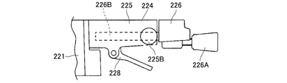
図13に示されるように突出部224は、ターンテーブル本体部222Aから延出される基部225と突出部224の延出方向先端に位置する先端部226とから主に構成されている。先端部226の先端部分にはハンドル226Aが設けられており、基部225と対向する部分には、左右方向に並列する一対のスライドバー226B、226Bが突出部224延出方向と略平行になるように設けられている。
As shown in FIG. 13, the protruding
基部225の先端部226と対向する部分には、一対の支持部225A、225Aがスライドバー226B、226Bと対向するように設けられている。これら一対の支持部225A、225Aにはそれぞれスライドバー226Bが挿入・摺動可能な孔が形成されており、この孔内にそれぞれスライドバー226B、226Bが挿入されて保持されている。基部225の両側面であって支持部225A、225Aに対応する箇所には、それぞれネジ穴が形成されてこのネジ穴にネジ225B、225Bが螺合しており、ネジ225B、225Bは螺合した状態で支持部225A、225Aに形成された孔内にその先端が突出可能となっている。
A pair of
卓上切断機201において切断作業を行う場合には、図13及び図14に示されるように、先端部226を突出方向先端側に移動させてネジ225B、225Bを締めてスライドバー226B、226Bを固定し、先端部226を移動不能とする。
When performing a cutting operation with the
切断作業後、卓上切断機201を収納する場合には、図15に示されるように、先端部226を基部225に近接させた位置に配置する。これにより突出部224のターンテーブル本体部222Aからの突出量が減少し、移送性等が向上する。
When the
本発明の卓上切断機は、上記した実施の形態に限定されず、特許請求の範囲に記載した範囲内において種々の変形や改良が可能である。例えば第一〜第三の実施の形態においては、切断本体部が前後にスライドする卓上切断機について説明したが、これに限らず、スライドしない卓上切断機についても同様に突出部を備える卓上切断機であれば、本発明を適応することができる。また第一〜第三の実施の形態では、スライド支持部にスライドバーが設けられてスライドバー上を揺動支持部がスライドする形態をとったが、これに限らず、揺動支持部側にスライドバーが設けられて、スライドバーとスライド支持部との間の摺動により揺動支持部が前後にスライドする構成をとっても良い。 The tabletop cutting machine of the present invention is not limited to the above-described embodiment, and various modifications and improvements can be made within the scope described in the claims. For example, in the first to third embodiments, the tabletop cutting machine in which the cutting main body part slides back and forth has been described. If so, the present invention can be applied. In the first to third embodiments, the slide support portion is provided with a slide bar, and the swing support portion slides on the slide bar. A configuration may be adopted in which a slide bar is provided, and the swinging support portion slides back and forth by sliding between the slide bar and the slide support portion.
第一の実施の形態では、回動角度調整機構により、先端部の上面と基部の上面とを同一平面上に位置するようにしたが、第二及び第三の実施の形態においても、基部に対する先端部の位置を調整する機構を備えていてもよい。 In the first embodiment, the upper surface of the distal end portion and the upper surface of the base portion are positioned on the same plane by the rotation angle adjustment mechanism. However, in the second and third embodiments as well, You may provide the mechanism which adjusts the position of a front-end | tip part.
また第一〜第三の実施の形態において、安全性を高めるために、先端部が非支持位置にある状態では、スイッチをONにしてもモータが起動しないように作用する安全機能、例えばモータの電力供給を遮断するスイッチを設けてもよい。 In the first to third embodiments, in order to enhance safety, in a state where the tip is in the non-supporting position, a safety function that acts so that the motor does not start even when the switch is turned on, for example, the motor A switch for cutting off the power supply may be provided.
1・・卓上丸鋸 2・・ベース部 3・・切断部 4・・支持部 5・・切断本体部
6・・丸鋸刃 21・・ベース 21A・・左ベース 21B・・右ベース
22・・ターンテーブル 22A・・ターンテーブル本体部 21C・・規制部材
22C・・中心軸 22a・・溝部 21b・・凹部 23・・フェンス
23A・・左フェンス 23B・・右フェンス 23C・・固定ネジ 24・・突出部
25・・基部 25A・・軸 25B・・突き当て部 26・・先端部
26A・・ハンドル 26B・・固定機構部 26C・・ピン 26D・・ネジ部
26a・・第一保持孔 26b・・第二保持孔 27・・切断部支持部
27A・・傾動軸 27B・・傾動支持部 28・・規制操作部 28A・・規制レバー
28B・・軸部 28C・・伝達部 28D・・第一腕部 28E・・第二腕部
29・・係止部 29A・・フレーム 29B・・スライド部 29C・・バネ
29D・・凸部 29E・・当接部 41・・揺動支持部 41A・・揺動軸
41B・・バネ 42・・スライド支持部 42A・・傾動固定部
43・・スライドバー 44・・スライド部 44A・・ネジ 45・・レーザ発振器
51・・ハウジング 52・・モータ 53・・ハンドル 53A・・スイッチ
54・・移動用ハンドル 55・・鋸刃カバー W・・木材
1. ・ Tabletop circular saw 2. ・
Claims (11)
該ベース上に支持され該ベースに対して回動可能なターンテーブルと、
該ターンテーブルに設けられ該ターンテーブルの上方で切断刃を揺動可能に支持する切断部と、
該ベース及び該ターンテーブルに関連して該ターンテーブルを該ベースに対して回動不能に固定可能な固定機構と、を備え、
該ターンテーブルは、該切断刃が揺動して交わる箇所となるターンテーブル本体と、該ターンテーブル本体と該切断刃とが交わる交線の延長線上にあって該ターンテーブル本体外周から該交線の延長線方向に突出する突出部とを有し、該ターンテーブル本体及び該突出部は該ベースと共に該加工部材を支持するように構成され、
該突出部は該ターンテーブル本体外周からの突出量を変更可能であることを特徴とする卓上切断機。 A base for supporting the workpiece,
A turntable supported on the base and rotatable with respect to the base;
A cutting portion provided on the turntable and supporting the cutting blade so as to be swingable above the turntable;
A fixing mechanism capable of non-rotatably fixing the turntable relative to the base in relation to the base and the turntable;
The turntable is located on an extension line of a turntable body where the cutting blades oscillate and intersect, and an intersection line between the turntable body and the cutting blades, and the line of intersection from the outer periphery of the turntable body The turntable body and the protrusion are configured to support the workpiece together with the base,
The desktop cutting machine characterized in that the protruding portion can change the protruding amount from the outer periphery of the turntable body.
該突出部の突出量変化は該基部に対する該先端部の位置変化により達成されることを特徴とする請求項1に記載の卓上切断機。 The projecting portion includes a base portion provided integrally with the turntable body, and a tip portion positioned on the tip side of the base portion and supported by the base portion ,
The tabletop cutting machine according to claim 1, wherein a change in the amount of protrusion of the protrusion is achieved by a change in the position of the tip with respect to the base.
該先端部は、該基部の延出方向と該先端部の延出方向とが同一となる該支持位置と該基部の延出方向と該先端部の延出方向とが略直交する非支持位置との間を回動可能に回動軸で軸支されていることを特徴とする請求項3に記載の卓上切断機。 The base includes a rotation shaft extending in a direction substantially orthogonal to the extending direction of the intersection line,
The distal end portion is an unsupported position in which the extending direction of the base portion and the extending direction of the distal end portion are the same, and the extending direction of the base portion and the extending direction of the distal end portion are substantially orthogonal to each other. The tabletop cutting machine according to claim 3, wherein the tabletop cutting machine is pivotally supported by a rotation shaft so as to be rotatable between the two.
該回動軸は該基部上面近傍に該基部上面と該回動軸の軸方向が略平行になるように設けられ、
該先端部が該支持位置にある状態で該基部と該先端部との互いに対面する位置には、該先端部の該基部に対する回動角度を調整する回動角度調整機構が設けられていることを特徴とする請求項4または請求項5のいずれかに記載の卓上切断機。 The base has a base top surface facing the workpiece;
The pivot shaft is provided near the upper surface of the base so that the upper surface of the base and the axial direction of the pivot shaft are substantially parallel,
A rotation angle adjusting mechanism for adjusting a rotation angle of the tip portion with respect to the base portion is provided at a position where the base portion and the tip portion face each other with the tip portion being in the support position. A tabletop cutting machine according to any one of claims 4 and 5, wherein:
該基部に設けられて該係止部と係合可能であると共に該係止部に対する係合・離脱を選択的に操作可能な係合部材と、を備えることを特徴とする請求項1乃至請求項8のいずれか一に記載の卓上切断機。 A plurality of locking portions provided at a circular arc position around the rotation axis of the turntable of the base;
An engagement member provided on the base and capable of engaging with the locking portion and capable of selectively operating engagement / disengagement with respect to the locking portion. Item 9. The tabletop cutting machine according to any one of Items 8 to 9.
該支持部は、該切断本体部を揺動可能に支持する揺動支持部と、該ターンテーブルの回動中心に対して該突出部の反対位置に設けられ該揺動支持部を保持すると共に該交線と略平行な方向に該揺動支持部を移動可能とするスライド支持部と、を有し、
該移動機構は、該揺動支持部と該スライド支持部から構成されることを特徴とする請求項10に記載の卓上切断機。 The cutting part includes a cutting body part that rotatably supports a cutting blade, and a support part that is supported by the turntable and supports the cutting body part,
The support portion is provided at a position opposite to the projecting portion with respect to a swing support portion for swingably supporting the cutting main body portion and a rotation center of the turntable, and holds the swing support portion. A slide support that allows the swing support to move in a direction substantially parallel to the line of intersection;
The tabletop cutting machine according to claim 10, wherein the moving mechanism includes the swing support portion and the slide support portion.
Priority Applications (5)
| Application Number | Priority Date | Filing Date | Title |
|---|---|---|---|
| JP2006062627A JP4552873B2 (en) | 2006-03-08 | 2006-03-08 | Tabletop cutting machine |
| US11/682,972 US7845260B2 (en) | 2006-03-08 | 2007-03-07 | Miter saw |
| DE200710011167 DE102007011167B4 (en) | 2006-03-08 | 2007-03-07 | Miter Saw |
| CNB2007100855048A CN100525974C (en) | 2006-03-08 | 2007-03-07 | Miter saw |
| TW96107980A TWI318920B (en) | 2006-03-08 | 2007-03-08 | Miter saw |
Applications Claiming Priority (1)
| Application Number | Priority Date | Filing Date | Title |
|---|---|---|---|
| JP2006062627A JP4552873B2 (en) | 2006-03-08 | 2006-03-08 | Tabletop cutting machine |
Publications (3)
| Publication Number | Publication Date |
|---|---|
| JP2007237544A JP2007237544A (en) | 2007-09-20 |
| JP2007237544A5 JP2007237544A5 (en) | 2008-07-17 |
| JP4552873B2 true JP4552873B2 (en) | 2010-09-29 |
Family
ID=38516366
Family Applications (1)
| Application Number | Title | Priority Date | Filing Date |
|---|---|---|---|
| JP2006062627A Active JP4552873B2 (en) | 2006-03-08 | 2006-03-08 | Tabletop cutting machine |
Country Status (5)
| Country | Link |
|---|---|
| US (1) | US7845260B2 (en) |
| JP (1) | JP4552873B2 (en) |
| CN (1) | CN100525974C (en) |
| DE (1) | DE102007011167B4 (en) |
| TW (1) | TWI318920B (en) |
Families Citing this family (13)
| Publication number | Priority date | Publication date | Assignee | Title |
|---|---|---|---|---|
| US20060243113A1 (en) * | 2005-04-29 | 2006-11-02 | Kaye Thomas R Jr | Bevel lock assembly for miter saws |
| DE202008000559U1 (en) * | 2008-01-14 | 2009-05-28 | Metabowerke Gmbh | Chop saw with a transport lock |
| JP5835611B2 (en) * | 2011-11-29 | 2015-12-24 | 日立工機株式会社 | Sliding tabletop cutting machine |
| CN102728889B (en) * | 2012-07-11 | 2014-11-12 | 宁波德丰动力科技有限公司 | Cutting machine |
| CN103894669B (en) * | 2012-12-26 | 2016-08-17 | 苏州宝时得电动工具有限公司 | Diagonal cutting saw |
| CN103586532B (en) | 2013-11-08 | 2016-01-06 | 锐奇控股股份有限公司 | Mitre saw |
| CN204604466U (en) * | 2015-04-17 | 2015-09-02 | 青岛金岭电器有限公司 | Workbench turns to quick-locking mechanism |
| EP3283250B1 (en) * | 2015-04-17 | 2022-06-08 | Robert Bosch GmbH | Motorized saw assembly and method of operating |
| US9833849B2 (en) | 2016-01-18 | 2017-12-05 | Tti (Macao Commercial Offshore) Limited | Miter saw |
| HUE047532T2 (en) | 2017-11-15 | 2020-04-28 | Scheppach Fabrikation Holzbearbeitungsmaschinen Gmbh | Bevel saw and workpiece support for same |
| US10898960B2 (en) * | 2018-03-28 | 2021-01-26 | Black & Decker Inc. | Miter saw |
| JP7419112B2 (en) * | 2019-08-23 | 2024-01-22 | 株式会社マキタ | tabletop cutting machine |
| US11135664B2 (en) * | 2019-08-27 | 2021-10-05 | Robert Bosch Power Tools GmbH | Table saw with a bevel pivot axis alignment arrangement |
Citations (5)
| Publication number | Priority date | Publication date | Assignee | Title |
|---|---|---|---|---|
| JPH0767809A (en) * | 1993-09-03 | 1995-03-14 | Sanyo Electric Co Ltd | Upright type vacuum cleaner |
| JPH07256602A (en) * | 1994-03-24 | 1995-10-09 | Ryobi Ltd | Circular saw machine |
| JP2001197801A (en) * | 2000-01-18 | 2001-07-24 | Honda Motor Co Ltd | Handle mechanism of ambulatory tiller |
| JP2002200601A (en) * | 2000-12-28 | 2002-07-16 | Makita Corp | Sliding circular sawing machine |
| JP2005279933A (en) * | 2004-03-26 | 2005-10-13 | Hitachi Koki Co Ltd | Bench cutter |
Family Cites Families (29)
| Publication number | Priority date | Publication date | Assignee | Title |
|---|---|---|---|---|
| US2146777A (en) * | 1936-11-09 | 1939-02-14 | Levi W Strong | Saw handle |
| US4152961A (en) * | 1978-01-18 | 1979-05-08 | The Singer Company | Radial saw |
| US4219899A (en) * | 1979-01-24 | 1980-09-02 | Gaetano Ricciuti | Paint pad assembly |
| US4694720A (en) * | 1986-04-08 | 1987-09-22 | Delta International Machinery Corp. | Miter box construction |
| US5235889A (en) * | 1992-03-25 | 1993-08-17 | Delta International Machinery Corp. | Compound miter saw |
| US5265511A (en) * | 1992-08-13 | 1993-11-30 | Milwaukee Electric Tool Corporation | Controlled axial position hinge assembly |
| NZ250875A (en) | 1993-02-22 | 1997-10-24 | Mcneil Ppc Inc | Absorbent pad comprising an adhesive layer which contacts and follows the contour of recess(s) in the garment side surface of the pad |
| US5425294A (en) * | 1993-06-03 | 1995-06-20 | Hitachi Koki Haramachi Co., Ltd. | Desk-top cutting machine with tiltable saw |
| US6971297B1 (en) * | 1995-10-10 | 2005-12-06 | Black & Decker Inc. | Guard and control apparatuses for sliding compound miter saw |
| US6474206B1 (en) * | 1995-12-12 | 2002-11-05 | Black & Decker Inc. | Miter saw with wear plates and orientation system therefor |
| US6470778B1 (en) * | 1998-05-20 | 2002-10-29 | Black & Decker Inc. | Dust collector for a power tool |
| US6272960B1 (en) | 1998-06-03 | 2001-08-14 | Black & Decker Inc. | Chop saw |
| US6044740A (en) * | 1998-09-28 | 2000-04-04 | Werkheiser; Lester E. | Push stick |
| US6513412B2 (en) * | 2001-01-09 | 2003-02-04 | Porter Cable Corp. | Adjustment mechanism |
| US6550363B2 (en) * | 2001-04-10 | 2003-04-22 | Cai Bai He | Extendible compound miter saw |
| US6810780B2 (en) * | 2001-05-10 | 2004-11-02 | Black & Decker Inc. | Miter detent override for a sliding compound miter saw |
| JP3867554B2 (en) | 2001-11-14 | 2007-01-10 | 日立工機株式会社 | Left and right inclined tabletop cutting machine |
| US7127977B2 (en) * | 2002-02-11 | 2006-10-31 | Porter-Cable/Delta | Remotely actuated beveling systems for a miter saw |
| US20030200852A1 (en) * | 2002-04-30 | 2003-10-30 | Ezequiel Romo | Miter cut fine adjustment mechanism |
| JP4034149B2 (en) | 2002-08-30 | 2008-01-16 | 株式会社不二工機 | Three-way valve |
| US6886440B2 (en) * | 2002-09-19 | 2005-05-03 | Black & Decker Inc. | Slide miter saw |
| US7201090B2 (en) * | 2002-10-16 | 2007-04-10 | Robert Bosch Gmbh | Front-accessible bevel locking system |
| US6769338B2 (en) | 2002-10-16 | 2004-08-03 | Credo Technology Corporation | Multiple position switch handle with locking mechanism |
| JP4662299B2 (en) | 2004-07-26 | 2011-03-30 | 日立工機株式会社 | Tabletop cutting machine |
| DE202004004929U1 (en) | 2004-03-26 | 2004-06-09 | Lutz Gmbh Maschinenbau | Cross=cut or mitre saw, has sawblade arm pivotally connected to holder part which can be slid along guide |
| US20050247178A1 (en) * | 2004-04-15 | 2005-11-10 | Hetcher Jason D | Power tool having an elastomeric material |
| CN1305555C (en) | 2004-05-18 | 2007-03-21 | 浙江大学 | Water-soluble ion liquid synthesizing method |
| TWM265199U (en) * | 2004-06-02 | 2005-05-21 | Rexon Ind Corp Ltd | Angle indication mechanism for circular sawing machine |
| CN2723154Y (en) | 2004-08-16 | 2005-09-07 | 青岛地恩地机电科技股份有限公司 | Round saw blade regulating mechanism for desk saw |
-
2006
- 2006-03-08 JP JP2006062627A patent/JP4552873B2/en active Active
-
2007
- 2007-03-07 US US11/682,972 patent/US7845260B2/en active Active
- 2007-03-07 DE DE200710011167 patent/DE102007011167B4/en active Active
- 2007-03-07 CN CNB2007100855048A patent/CN100525974C/en active Active
- 2007-03-08 TW TW96107980A patent/TWI318920B/en active
Patent Citations (5)
| Publication number | Priority date | Publication date | Assignee | Title |
|---|---|---|---|---|
| JPH0767809A (en) * | 1993-09-03 | 1995-03-14 | Sanyo Electric Co Ltd | Upright type vacuum cleaner |
| JPH07256602A (en) * | 1994-03-24 | 1995-10-09 | Ryobi Ltd | Circular saw machine |
| JP2001197801A (en) * | 2000-01-18 | 2001-07-24 | Honda Motor Co Ltd | Handle mechanism of ambulatory tiller |
| JP2002200601A (en) * | 2000-12-28 | 2002-07-16 | Makita Corp | Sliding circular sawing machine |
| JP2005279933A (en) * | 2004-03-26 | 2005-10-13 | Hitachi Koki Co Ltd | Bench cutter |
Also Published As
| Publication number | Publication date |
|---|---|
| TW200800534A (en) | 2008-01-01 |
| CN101032770A (en) | 2007-09-12 |
| US7845260B2 (en) | 2010-12-07 |
| DE102007011167B4 (en) | 2009-09-10 |
| JP2007237544A (en) | 2007-09-20 |
| TWI318920B (en) | 2010-01-01 |
| US20070214927A1 (en) | 2007-09-20 |
| CN100525974C (en) | 2009-08-12 |
| DE102007011167A1 (en) | 2007-11-08 |
Similar Documents
| Publication | Publication Date | Title |
|---|---|---|
| JP4552873B2 (en) | Tabletop cutting machine | |
| JP5835611B2 (en) | Sliding tabletop cutting machine | |
| JP4254429B2 (en) | Tabletop slide cutting machine | |
| JP2007223133A (en) | Portable cutting machine | |
| JP2007223127A (en) | Table cutter | |
| JP5313081B2 (en) | Inclination positioning mechanism of cutting machine body in tabletop cutting machine | |
| JP2009028833A (en) | Supporting leg of bench type cutting-off machine | |
| US9533361B2 (en) | Cutting machines | |
| JP2009126059A (en) | Vice device and cutter | |
| JP2010005750A (en) | Desktop cutter | |
| JP6274522B2 (en) | Cutting machine | |
| JP2008073920A (en) | Table cutter | |
| JP4748362B2 (en) | Tabletop cutting machine | |
| JP4528757B2 (en) | Portable electric cutting machine | |
| JP2008100356A (en) | Slide type bench cutter | |
| JP4692827B2 (en) | Tabletop cutting machine | |
| JP6215047B2 (en) | Tabletop cutting tool | |
| JP2010076059A (en) | Portable cutting machine | |
| JP2008044034A (en) | Cutter | |
| JP5344891B2 (en) | Inclined support mechanism of the main body of the cutting machine in the tabletop cutting machine | |
| JP2008229876A (en) | Bench cutter | |
| JP2008100355A (en) | Slide type bench cutter | |
| JP2018083263A (en) | Desk cutter | |
| JP2009067016A (en) | Cutter, and packing method of cutter | |
| JPH07256602A (en) | Circular saw machine |
Legal Events
| Date | Code | Title | Description |
|---|---|---|---|
| A521 | Request for written amendment filed |
Free format text: JAPANESE INTERMEDIATE CODE: A523 Effective date: 20080604 |
|
| A621 | Written request for application examination |
Free format text: JAPANESE INTERMEDIATE CODE: A621 Effective date: 20080604 |
|
| A977 | Report on retrieval |
Free format text: JAPANESE INTERMEDIATE CODE: A971007 Effective date: 20091215 |
|
| A131 | Notification of reasons for refusal |
Free format text: JAPANESE INTERMEDIATE CODE: A131 Effective date: 20091222 |
|
| A521 | Request for written amendment filed |
Free format text: JAPANESE INTERMEDIATE CODE: A523 Effective date: 20100219 |
|
| TRDD | Decision of grant or rejection written | ||
| A01 | Written decision to grant a patent or to grant a registration (utility model) |
Free format text: JAPANESE INTERMEDIATE CODE: A01 Effective date: 20100622 |
|
| A01 | Written decision to grant a patent or to grant a registration (utility model) |
Free format text: JAPANESE INTERMEDIATE CODE: A01 |
|
| A61 | First payment of annual fees (during grant procedure) |
Free format text: JAPANESE INTERMEDIATE CODE: A61 Effective date: 20100705 |
|
| FPAY | Renewal fee payment (event date is renewal date of database) |
Free format text: PAYMENT UNTIL: 20130723 Year of fee payment: 3 |
|
| R150 | Certificate of patent or registration of utility model |
Ref document number: 4552873 Country of ref document: JP Free format text: JAPANESE INTERMEDIATE CODE: R150 Free format text: JAPANESE INTERMEDIATE CODE: R150 |
|
| FPAY | Renewal fee payment (event date is renewal date of database) |
Free format text: PAYMENT UNTIL: 20140723 Year of fee payment: 4 |
|
| S533 | Written request for registration of change of name |
Free format text: JAPANESE INTERMEDIATE CODE: R313533 |
|
| R350 | Written notification of registration of transfer |
Free format text: JAPANESE INTERMEDIATE CODE: R350 |