JP2005279933A - Bench cutter - Google Patents
Bench cutter Download PDFInfo
- Publication number
- JP2005279933A JP2005279933A JP2004092737A JP2004092737A JP2005279933A JP 2005279933 A JP2005279933 A JP 2005279933A JP 2004092737 A JP2004092737 A JP 2004092737A JP 2004092737 A JP2004092737 A JP 2004092737A JP 2005279933 A JP2005279933 A JP 2005279933A
- Authority
- JP
- Japan
- Prior art keywords
- circular saw
- holder
- saw blade
- guide bar
- cutting machine
- Prior art date
- Legal status (The legal status is an assumption and is not a legal conclusion. Google has not performed a legal analysis and makes no representation as to the accuracy of the status listed.)
- Pending
Links
- 238000005520 cutting process Methods 0.000 claims description 55
- 239000000428 dust Substances 0.000 claims description 10
- 238000007599 discharging Methods 0.000 claims description 2
- 230000002093 peripheral effect Effects 0.000 claims 3
- 230000001678 irradiating effect Effects 0.000 claims 1
- 238000000034 method Methods 0.000 description 5
- 230000005484 gravity Effects 0.000 description 4
- 230000001105 regulatory effect Effects 0.000 description 3
- 230000005540 biological transmission Effects 0.000 description 2
- 230000007423 decrease Effects 0.000 description 2
- 239000000463 material Substances 0.000 description 2
- 230000001276 controlling effect Effects 0.000 description 1
- 238000009434 installation Methods 0.000 description 1
- 230000002618 waking effect Effects 0.000 description 1
- 238000004804 winding Methods 0.000 description 1
Images


Classifications
-
- B—PERFORMING OPERATIONS; TRANSPORTING
- B23—MACHINE TOOLS; METAL-WORKING NOT OTHERWISE PROVIDED FOR
- B23D—PLANING; SLOTTING; SHEARING; BROACHING; SAWING; FILING; SCRAPING; LIKE OPERATIONS FOR WORKING METAL BY REMOVING MATERIAL, NOT OTHERWISE PROVIDED FOR
- B23D45/00—Sawing machines or sawing devices with circular saw blades or with friction saw discs
- B23D45/04—Sawing machines or sawing devices with circular saw blades or with friction saw discs with a circular saw blade or the stock carried by a pivoted lever
- B23D45/042—Sawing machines or sawing devices with circular saw blades or with friction saw discs with a circular saw blade or the stock carried by a pivoted lever with the saw blade carried by a pivoted lever
- B23D45/046—Sawing machines or sawing devices with circular saw blades or with friction saw discs with a circular saw blade or the stock carried by a pivoted lever with the saw blade carried by a pivoted lever the pivoted lever being mounted on a carriage
- B23D45/048—Sawing machines or sawing devices with circular saw blades or with friction saw discs with a circular saw blade or the stock carried by a pivoted lever with the saw blade carried by a pivoted lever the pivoted lever being mounted on a carriage the saw blade being adjustable according to angle of cut
-
- B—PERFORMING OPERATIONS; TRANSPORTING
- B23—MACHINE TOOLS; METAL-WORKING NOT OTHERWISE PROVIDED FOR
- B23D—PLANING; SLOTTING; SHEARING; BROACHING; SAWING; FILING; SCRAPING; LIKE OPERATIONS FOR WORKING METAL BY REMOVING MATERIAL, NOT OTHERWISE PROVIDED FOR
- B23D59/00—Accessories specially designed for sawing machines or sawing devices
- B23D59/001—Measuring or control devices, e.g. for automatic control of work feed pressure on band saw blade
- B23D59/002—Measuring or control devices, e.g. for automatic control of work feed pressure on band saw blade for the position of the saw blade
- B23D59/003—Indicating the cutting plane on the workpiece, e.g. by projecting a laser beam
-
- Y—GENERAL TAGGING OF NEW TECHNOLOGICAL DEVELOPMENTS; GENERAL TAGGING OF CROSS-SECTIONAL TECHNOLOGIES SPANNING OVER SEVERAL SECTIONS OF THE IPC; TECHNICAL SUBJECTS COVERED BY FORMER USPC CROSS-REFERENCE ART COLLECTIONS [XRACs] AND DIGESTS
- Y10—TECHNICAL SUBJECTS COVERED BY FORMER USPC
- Y10T—TECHNICAL SUBJECTS COVERED BY FORMER US CLASSIFICATION
- Y10T83/00—Cutting
- Y10T83/222—With receptacle or support for cut product
-
- Y—GENERAL TAGGING OF NEW TECHNOLOGICAL DEVELOPMENTS; GENERAL TAGGING OF CROSS-SECTIONAL TECHNOLOGIES SPANNING OVER SEVERAL SECTIONS OF THE IPC; TECHNICAL SUBJECTS COVERED BY FORMER USPC CROSS-REFERENCE ART COLLECTIONS [XRACs] AND DIGESTS
- Y10—TECHNICAL SUBJECTS COVERED BY FORMER USPC
- Y10T—TECHNICAL SUBJECTS COVERED BY FORMER US CLASSIFICATION
- Y10T83/00—Cutting
- Y10T83/768—Rotatable disc tool pair or tool and carrier
- Y10T83/7684—With means to support work relative to tool[s]
- Y10T83/7693—Tool moved relative to work-support during cutting
- Y10T83/7697—Tool angularly adjustable relative to work-support
-
- Y—GENERAL TAGGING OF NEW TECHNOLOGICAL DEVELOPMENTS; GENERAL TAGGING OF CROSS-SECTIONAL TECHNOLOGIES SPANNING OVER SEVERAL SECTIONS OF THE IPC; TECHNICAL SUBJECTS COVERED BY FORMER USPC CROSS-REFERENCE ART COLLECTIONS [XRACs] AND DIGESTS
- Y10—TECHNICAL SUBJECTS COVERED BY FORMER USPC
- Y10T—TECHNICAL SUBJECTS COVERED BY FORMER US CLASSIFICATION
- Y10T83/00—Cutting
- Y10T83/768—Rotatable disc tool pair or tool and carrier
- Y10T83/7684—With means to support work relative to tool[s]
- Y10T83/7701—Supporting surface and tool axis angularly related
- Y10T83/7705—Adjustable angular relationship
-
- Y—GENERAL TAGGING OF NEW TECHNOLOGICAL DEVELOPMENTS; GENERAL TAGGING OF CROSS-SECTIONAL TECHNOLOGIES SPANNING OVER SEVERAL SECTIONS OF THE IPC; TECHNICAL SUBJECTS COVERED BY FORMER USPC CROSS-REFERENCE ART COLLECTIONS [XRACs] AND DIGESTS
- Y10—TECHNICAL SUBJECTS COVERED BY FORMER USPC
- Y10T—TECHNICAL SUBJECTS COVERED BY FORMER US CLASSIFICATION
- Y10T83/00—Cutting
- Y10T83/768—Rotatable disc tool pair or tool and carrier
- Y10T83/7684—With means to support work relative to tool[s]
- Y10T83/7722—Support and tool relatively adjustable
- Y10T83/7726—By movement of the tool
-
- Y—GENERAL TAGGING OF NEW TECHNOLOGICAL DEVELOPMENTS; GENERAL TAGGING OF CROSS-SECTIONAL TECHNOLOGIES SPANNING OVER SEVERAL SECTIONS OF THE IPC; TECHNICAL SUBJECTS COVERED BY FORMER USPC CROSS-REFERENCE ART COLLECTIONS [XRACs] AND DIGESTS
- Y10—TECHNICAL SUBJECTS COVERED BY FORMER USPC
- Y10T—TECHNICAL SUBJECTS COVERED BY FORMER US CLASSIFICATION
- Y10T83/00—Cutting
- Y10T83/768—Rotatable disc tool pair or tool and carrier
- Y10T83/7755—Carrier for rotatable tool movable during cutting
- Y10T83/7763—Tool carrier reciprocable rectilinearly
- Y10T83/7768—With means to adjust path of reciprocation
- Y10T83/7772—Angular relative to previous path
-
- Y—GENERAL TAGGING OF NEW TECHNOLOGICAL DEVELOPMENTS; GENERAL TAGGING OF CROSS-SECTIONAL TECHNOLOGIES SPANNING OVER SEVERAL SECTIONS OF THE IPC; TECHNICAL SUBJECTS COVERED BY FORMER USPC CROSS-REFERENCE ART COLLECTIONS [XRACs] AND DIGESTS
- Y10—TECHNICAL SUBJECTS COVERED BY FORMER USPC
- Y10T—TECHNICAL SUBJECTS COVERED BY FORMER US CLASSIFICATION
- Y10T83/00—Cutting
- Y10T83/768—Rotatable disc tool pair or tool and carrier
- Y10T83/7755—Carrier for rotatable tool movable during cutting
- Y10T83/7788—Tool carrier oscillated or rotated
-
- Y—GENERAL TAGGING OF NEW TECHNOLOGICAL DEVELOPMENTS; GENERAL TAGGING OF CROSS-SECTIONAL TECHNOLOGIES SPANNING OVER SEVERAL SECTIONS OF THE IPC; TECHNICAL SUBJECTS COVERED BY FORMER USPC CROSS-REFERENCE ART COLLECTIONS [XRACs] AND DIGESTS
- Y10—TECHNICAL SUBJECTS COVERED BY FORMER USPC
- Y10T—TECHNICAL SUBJECTS COVERED BY FORMER US CLASSIFICATION
- Y10T83/00—Cutting
- Y10T83/869—Means to drive or to guide tool
- Y10T83/8773—Bevel or miter cut
Abstract
Description
本発明は、丸鋸部がベース上面に対して揺動可能であると共に、丸鋸刃の側面に沿う方向に摺動可能な構成をした卓上切断機に関するものである。 The present invention relates to a tabletop cutting machine in which a circular saw portion is swingable with respect to an upper surface of a base and is slidable in a direction along a side surface of the circular saw blade.
従来の丸鋸部がベース上面に対して揺動可能であると共に丸鋸刃の側面に沿う方向に摺動可能な構成をした卓上切断機は、ベース後方上部のホルダがガイドバーを摺動可能に保持し、ガイドバーの前端部に支持部材、支持部材に丸鋸刃、モータを有する丸鋸部が揺動可能に取付けられた構成をしている。(例えば、特許文献1参照)
また、ホルダに丸鋸部を揺動可能に支持させると共に、ホルダとベース部との間にガイドバーを設け、ベース部とガイドバーが相対的に摺動可能な構成をした卓上切断機がある。(例えば、特許文献2参照)
上記した卓上切断機はベース部に対してホルダが傾動可能となっており、傾動によってベース部上面に対する丸鋸刃側面の角度が傾斜可能な構成をしている。
The conventional circular saw part can swing with respect to the upper surface of the base and slide along the side of the circular saw blade. And a circular saw portion having a motor and a circular saw blade and a motor are swingably attached to the front end portion of the guide bar. (For example, see Patent Document 1)
In addition, there is a tabletop cutting machine in which a circular saw portion is swingably supported by a holder and a guide bar is provided between the holder and the base portion so that the base portion and the guide bar can slide relative to each other. . (For example, see Patent Document 2)
In the above-described tabletop cutting machine, the holder can tilt with respect to the base portion, and the angle of the side surface of the circular saw blade with respect to the upper surface of the base portion can be tilted by tilting.
上記した従来の卓上切断機は、丸鋸部を前方側(ホルダから離れる方向側)に移動させた際には、工具全体がコンパクトとなるようにガイドバーが摺動するものであるが、丸鋸部を後方側(ホルダ側)に移動させた際には、ガイドバーがホルダより後方側にベース部から後方端部が離れるように突出する(特許文献1)、あるいはホルダがベース部から離れるように移動する(特許文献2)ものであった。 In the conventional tabletop cutting machine described above, the guide bar slides so that the entire tool is compact when the circular saw portion is moved forward (the direction away from the holder). When the saw part is moved to the rear side (holder side), the guide bar protrudes rearward from the base so that the rear end part is separated from the base part (Patent Document 1), or the holder is separated from the base part. (Patent Document 2).
このため、ホルダの反ベース側すなわち後方側に壁や物等がある状態では切断作業を行うことができず、狭い場所での作業性が悪いものであった。 For this reason, cutting work cannot be performed in a state where there is a wall or an object on the opposite side of the holder, that is, the rear side, and workability in a narrow place is poor.
なお、卓上丸鋸を持ち運ぶ際には、通常丸鋸部を前方側に移動させ工具全体をコンパクト化した状態で持ち運ぶものであるが、この状態で壁や物の近傍にホルダが位置するように卓上丸鋸を設置した際には丸鋸部を後方側に移動させることができず、切断作業を行うことができないものであり、卓上丸鋸の設置の際にはガイドバーやホルダの移動量を考慮する必要があり操作性が悪いものであった。また、上記のように卓上丸鋸を持ち運ぶ際には卓上丸鋸をコンパクト化させる作業が必要があり、操作性が悪いものであった。 When carrying a tabletop circular saw, it is usually carried in a state where the circular saw part is moved forward and the entire tool is made compact. In this state, the holder is positioned near the wall or object. When a tabletop circular saw is installed, the circular saw part cannot be moved rearward and cutting work cannot be performed. When a tabletop circular saw is installed, the amount of movement of the guide bar and holder The operability was poor. Further, when carrying the tabletop circular saw as described above, it is necessary to make the tabletop circular saw compact, and the operability is poor.
また、ガイドバーを摺動可能に支持する部分に加わる摺動方向に直交した力が大きく、摺動性が低下する、あるいは摺動性の低下しにくい高価な構成とする必要があるものであった。 In addition, the force perpendicular to the sliding direction applied to the portion that supports the guide bar so as to be slidable is large, and it is necessary to have an expensive configuration in which the slidability decreases or the slidability does not easily decrease. It was.
本発明の目的は、上記欠点を解消し、小型化を図ると共に、作業スペースが小さい、操作性の良い卓上切断機を提供することである。 SUMMARY OF THE INVENTION An object of the present invention is to provide a tabletop cutting machine that eliminates the above-mentioned drawbacks, reduces the size, and has a small work space and good operability.
上記目的は、丸鋸刃の軸方向にほぼ直交すると共に前記ベース部上面に対してほぼ平行に延びる傾動軸によりベース部に対して傾動可能なホルダと、ベース部に対するホルダの傾動を規制する傾動規制手段と、ホルダに固定され、傾動軸とほぼ平行に延びるガイドバーを有するガイド部とを設け、支持部材をガイド部上で摺動・固定可能な構成とすることで達成される。 The purpose is to provide a holder that can be tilted with respect to the base portion by a tilting shaft that is substantially orthogonal to the axial direction of the circular saw blade and extends substantially parallel to the upper surface of the base portion, and tilting that restricts tilting of the holder with respect to the base portion. This is achieved by providing a restricting means and a guide portion having a guide bar fixed to the holder and extending substantially parallel to the tilting axis, and the support member can be slid and fixed on the guide portion.
本発明によれば、切断作業時にガイドバーがホルダから突出することや、ホルダがベース部から離れるように移動することがなく、製品の小型化を図ることができ、狭い場所等での切断作業が可能となると共に、摺動性及び操作性の向上を図ることができる卓上切断機を提供できるようになる。 According to the present invention, the guide bar does not protrude from the holder at the time of cutting work, and the holder does not move away from the base portion, so that the product can be reduced in size, and cutting work in a narrow place or the like. In addition, it is possible to provide a tabletop cutting machine that can improve slidability and operability.
また、ガイドバーを2本設けると共に、両者を結ぶ仮想線が丸鋸刃側面に対してほぼ平行となるように配置することにより、丸鋸部揺動時に支持部材の摺動部及びホルダのガイドバーを固定する部分に加わる荷重に対する剛性を向上させることができると共に、持ち運び時にガイドバーに加わる荷重に対する剛性を向上させることができるようになる。 Also, by providing two guide bars and arranging so that the imaginary line connecting the two is substantially parallel to the side surface of the circular saw blade, the sliding portion of the support member and the guide of the holder when the circular saw portion swings. The rigidity with respect to the load applied to the portion fixing the bar can be improved, and the rigidity with respect to the load applied to the guide bar during carrying can be improved.
また、少なくとも2本のガイドバーのホルダと反対側の端面には両者と係合する係合部材が設けられており、支持部材はホルダに当接することで丸鋸部のホルダ側への摺動が規制され、係合部材に当接することでホルダから離れる方向への摺動が規制される構成とすることで、容易に支持部材及び丸鋸部の抜け止めを行うことができるようになる。 Further, at least two guide bar end faces opposite to the holder are provided with engaging members that engage with both of them, and the support member comes into contact with the holder so that the circular saw portion slides toward the holder side. In this configuration, the sliding in the direction away from the holder is restricted by coming into contact with the engaging member, so that the supporting member and the circular saw portion can be easily prevented from coming off.
更に、電動機は丸鋸刃の側面の延長線と交差する部分を有するよう配置され、丸鋸部は電動機の回転力を丸鋸刃に伝達するためのベルト機構を有する構成とすることにより、丸鋸部における丸鋸刃の軸方向の寸法を小さくすることができるようになる。 Further, the electric motor is arranged so as to have a portion intersecting with the extension line of the side surface of the circular saw blade, and the circular saw portion has a belt mechanism for transmitting the rotational force of the electric motor to the circular saw blade. The axial dimension of the circular saw blade in the saw portion can be reduced.
更に、電動機はその軸が丸鋸刃の軸方向とほぼ平行となるように配置されている構成とすることによって、丸鋸部及び卓上切断機本体の高さ方向寸法を小さくすることができるようになる。 Furthermore, the electric motor has a configuration in which the shaft thereof is arranged substantially parallel to the axial direction of the circular saw blade, so that the size in the height direction of the circular saw portion and the tabletop cutting machine body can be reduced. become.
また、ガイドバーを2本とすると共に、支持部材のガイドバー外周部と当接可能な摺動部の少なくとも一方を、支持部材に対してガイドバーの径方向に移動可能とすることによって、一方の摺動部をガイドバーの径方向に移動させた際に他方の摺動部を支点と丸鋸部が回動し、これによりホルダに対する丸鋸刃の直角度を微調整することができるようになる。 In addition, two guide bars are provided, and at least one of the sliding portions that can come into contact with the outer periphery of the guide bar of the support member is movable with respect to the support member in the radial direction of the guide bar. When the sliding part is moved in the radial direction of the guide bar, the fulcrum and the circular saw part turn the other sliding part so that the perpendicularity of the circular saw blade with respect to the holder can be finely adjusted. become.
更に、一方のガイドバー外周部と当接可能な摺動部をボールベアリングとし、他方のガイドバー外周部と当接可能な摺動部をガイドバーの径方向に移動可能な摺動部とすると共に、他方のガイドバー外周部と当接可能な固定手段を支持部材に設けた構成とすることによって、支持部材におけるガイドバーの軸方向寸法を必要最低限なボールベアリングの軸方向寸法内で収めることができ、丸鋸部の摺動量の確保及び小型化を図ることができる。 Further, the sliding portion that can contact the outer periphery of one guide bar is a ball bearing, and the sliding portion that can contact the outer periphery of the other guide bar is a sliding portion that can move in the radial direction of the guide bar. At the same time, the support member is provided with a fixing means that can contact the outer periphery of the other guide bar, so that the axial dimension of the guide bar in the support member is kept within the minimum axial dimension of the ball bearing. Therefore, the sliding amount of the circular saw portion can be ensured and the size can be reduced.
また、支持部材は丸鋸刃側面の延長線上にレーザーを照射可能なレーザー照射装置を支持する構成とすることにより、切断前において切断部の位置確認を容易に行うことができるようになり、操作性を向上させることができるようになる。 In addition, the support member is configured to support a laser irradiation device that can irradiate a laser on the extended line of the side surface of the circular saw blade, so that the position of the cutting portion can be easily confirmed before cutting, and the operation Can be improved.
更に、ホルダに傾動軸とほぼ直交する方向に移動可能な操作部材を設け、操作部材の操作によってベース部に対するホルダの傾動の規制・解除を可能とした構成とすることによって、作業時にホルダ後方のスペースを気にする必要がないと共に、ホルダ後方に回らずとも傾動の規制・解除を行うことができ操作性の向上を図ることができる。また、卓上切断機における傾動軸の軸方向の寸法を小さくすることができるようになる。 Further, the holder is provided with an operation member that can move in a direction substantially perpendicular to the tilting axis, and the holder can be controlled to be tilted with respect to the base portion by operating the operation member. There is no need to worry about space, and tilting can be restricted and released without rotating to the rear of the holder, so that operability can be improved. In addition, it is possible to reduce the axial dimension of the tilt axis in the tabletop cutting machine.
更に、丸鋸部は切断作業時に発生する切粉を排出する切粉排出口と、切粉排出口に着脱可能に取付けられる集塵バックとを有し、集塵バックの端面はガイドバーの軸方向において最もベース部から離れる部分よりもベース部側に位置している構成とすることによって、壁際での作業時等に集塵バックによって卓上切断機の設置場所が制限されてしまうことがなく、作業性の向上を図ることができるようになる。 Furthermore, the circular saw portion has a chip discharge port for discharging chips generated during cutting work, and a dust collection bag that is detachably attached to the chip discharge port, and the end surface of the dust collection bag is a shaft of the guide bar. By adopting a configuration that is located closer to the base part than the part farthest from the base part in the direction, the installation location of the tabletop cutting machine is not limited by the dust collection back when working at the wall, etc. Workability can be improved.
更に、丸鋸部は持運び用のサブハンドルを有する構成とすることによって、持ち運び時の操作性を向上させることができるようになる。 Furthermore, the circular saw portion has a structure having a sub handle for carrying, so that the operability during carrying can be improved.
本発明卓上切断機の一実施形態を図1〜図8を用いて以下説明する。以下、卓上切断機を卓上丸鋸として説明する。 An embodiment of the tabletop cutting machine of the present invention will be described below with reference to FIGS. Hereinafter, the tabletop cutting machine will be described as a tabletop circular saw.
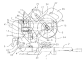
図に示す本発明卓上丸鋸は、被加工材35を載置可能なベース部1、2と、電動機であるモータ21を収納し、モータ21の駆動により回動する丸鋸刃14を回動可能に支持する丸鋸部12と、丸鋸刃14の軸方向とほぼ平行な揺動軸11により丸鋸部12を揺動可能に支持する支持部材8とを有し、ベース部1、2上面に対する丸鋸刃14側面の角度を変更可能な構成をしている。
The table-top circular saw of the present invention shown in the figure accommodates
ベース部は床面等に載置可能なベース1と、ベース1に埋設されベース1上面とほぼ面一となる上面を有し、上面に直交する回動軸を介して回動可能にベース1と連結されたターンテーブル2を有する構成をしている。作業時には、ベース部であるベース1及びターンテーブル2に被加工材35が載置可能となっている。
The base portion has a
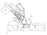
ベース1には上面とほぼ直交する押さえ面3a(図1に示す右側端面)を有する一対のフェンス3が設けられており、断面が直角形状をした図1に示すような被加工材35を切断加工する際にはフェンス3の押さえ面3aに被切断材35の一面を当接させた状態で切断作業を行うことにより、安定した切断作業を行うことができるようにしている。ターンテーブル2をベース1に対して回動させると、ターンテーブル2と連結されたホルダ5、ガイド部7、支持部材8及び丸鋸部12のフェンス3に対する位置が変化し、これによって、フェンス3の押さえ面3aと丸鋸刃14側面との角度が変化することとなり、フェンス3に当接された被加工材35を様々な角度で切断加工行うことができるようになっている。
The
図1に示すようにターンテーブル2の後方側(図1に示す左側)端部付近には、上方に立設するホルダ5が丸鋸刃14側面及びターンテーブル2上面とほぼ平行に延びた傾動軸4を介して接続されている。この傾動軸4を支点としてホルダ5はターンテーブル2に対して傾動可能となっている(図4及び図5)。
As shown in FIG. 1, the
また、ターンテーブル2の後方側端部には上方に突出した突出部2aが設けられ、この突出部2aにホルダ5に設けられた傾動規制手段を構成するクランプレバー6が押接されることでベース1に対するターンテーブル2の傾動が規制(固定)される。このように、クランプレバー6の操作によってホルダ5とターンテーブル2との傾動を固定・解除可能となっている。なお、図示しないがターンテーブル2の突出部分には傾動軸4を支点とした円弧状の長穴が設けられており、長穴内にホルダ5に取付けられたクランプレバー6の軸部が位置する構成となっている。
Further, a projecting
ホルダ5の上端部付近には、丸鋸刃14の側面及びベース部1の上面にほぼ平行に配列された穴部5cが2個形成されている(図6)。
Near the upper end of the
ホルダ5の穴部5cには、ほぼ同径あるいは若干大径のパイプ材からなる硬質のガイドバー7が挿入されている。本発明卓上丸鋸においては、ホルダ5に対するガイドバー7の抜け及び回動を防止するためにホルダ5に穴部5c内に突出可能な固定手段5dが設けられている(図6)。
A
ホルダ5の穴部5c内に挿入される本発明ガイド部である2本のガイドバー7はほぼ同じ長さ寸法のものであり、長さ寸法はターンテーブル2の長手方向よりも短いものである。
The two
ガイドバー7の前方(図1に示す右側)端部には、丸鋸刃14の側面及びベース部1の上面にほぼ平行に配列された2個の穴部9aが設けられた係合部材であるサポート9が取付けられている。サポート9は穴部9a内に突出可能な固定手段9bが設けられており、固定手段9bによってガイドバー7に対するサポート9の抜け止め及びガイドバー7の回動を防止している。
At the front end (right side shown in FIG. 1) of the
ガイドバー7上であってホルダ5とサポート9との間には、丸鋸部12の揺動軸11を支持する支持部材8が設けられている。支持部材8にはガイドバー7とほぼ同心の穴部8aが2個形成されており、一方の穴部8a(図3の下側穴部8a)内にはガイドバー7の外径寸法とほぼ同寸法の内径を有し、ガイドバー7外径部に当接可能な一方の摺動部であるボールベアリング8bが設けられている。他方の穴部8a(図3の上側穴部8a)内にはガイドバー7との間に他方の摺動部である2個の移動部材8cが設けられており、この移動部材8cは支持部材8に螺合したボルト8dの先端によって穴部8a内からの抜け落ちが防止されていると共に、ボルト8dの先端の押圧によって移動調整可能となっている。
A
また、支持部材8には上側穴部8a内に突出可能な固定手段であるノブ10が設けられており、ノブ10の先端がガイドバー7外径部を押圧することによって、ガイドバー7上で支持部材8の位置を固定可能となっている。
Further, the
ボルト8dの操作によって移動部材8cの位置を調整することにより、穴部8a内におけるガイドバー7の位置を調整することができる。すなわち、2個の移動部材8cを図3に示す左側方向に移動させれば支持部材8は下方のガイドバー7を支点として図示時計回りに回動し、これに伴って丸鋸部12及び丸鋸刃14もガイドバー7を支点として図示時計回りに回動することとなる。このように一方のガイドバー7を支点として支持部材8を回動調整可能な構成とすることによって、ベース1上面に対する丸鋸刃14側面の角度の微調整を行うことができるようにしている。
By adjusting the position of the moving
なお、支持部材8の穴部8aを有する部分の穴部8aの軸方向寸法は、一方の摺動部であるボールベアリング8bの軸方向寸法とほぼ同じ寸法で、支持部材8が摺動性を損なわない必要最低限以上の寸法となっており、他方の摺動部である移動部材8cを移動可能として角度微調整機構を備えさせると共に他方の摺動部近辺に固定手段を設けた構成としたことにより、支持部材8の寸法を小さく抑えることができ、卓上丸鋸本体の小型化、丸鋸部12の摺動量の確保を行うことができるようになる。
It should be noted that the axial dimension of the
2本のガイドバー7のホルダ5と反対側の端面には両者と係合する係合部材であるサポート9が設けられており、支持部材8はホルダ5に当接することで丸鋸部12のホルダ5側への摺動が規制され、サポート9に当接することでホルダ5から離れる方向への摺動が規制される構成となっており、容易に支持部材8及び丸鋸部12の抜け止めを行うことができるようになっている。
なお、本発明卓上丸鋸によれば、ガイドバー7上を摺動するのが支持部材8及び丸鋸部12のみであり、摺動時にボールベアリング8bに加わる摺動方向に直交した力を小さく抑えることができると共に、従来の卓上丸鋸のように摺動位置によってボールベアリング8bに加わる上記した摺動方向に直交する力が増加するものではないため、ボールベアリング8bの小型化を図ることができるものである。
According to the tabletop circular saw of the present invention, only the
図3に示すように支持部材8にはガイドバー7の軸方向と直交する方向に延びる揺動軸11が固定され、揺動軸11を介して支持部材8には丸鋸部12が連結されている(図1、図6)。
As shown in FIG. 3, a
図1及び図3に示すように支持部材8の揺動軸11下方には凹部8eが設けられ、凹部8e内にはレーザー発振器40が設けられている。レーザー発振器40は、少なくとも丸鋸刃14の軸方向に移動調整可能な構成をしており、丸鋸刃14の側面の延長線上に延びるレーザー光を被加工材35上に照射可能となっている。
As shown in FIGS. 1 and 3, a
また、揺動軸11外周にはスプリング13が設けられ、スプリング13によって丸鋸部12はベース部から丸鋸刃14が離れる方向(上方)に揺動するよう付勢されており、通常時には図示しないストッパ機構によって図1に示す最も上方(反ベース部側)に揺動した位置となる。切断加工は、スプリング13の付勢力に抗して丸鋸部12を揺動軸11を支点に下方(ベース部側)に揺動させることにより行なわれる。
Further, a
丸鋸部12を下方(ベース部側)に揺動させると、丸鋸刃14は図示しないターンテーブル2に設けられた溝部内に侵入し、所定量侵入した状態で図示しないストッパ機構によって図6に示すように揺動が停止される。
When the
本発明卓上丸鋸は、図6に示すように丸鋸部12をベース部側に揺動させた状態から丸鋸部12をホルダ5側に付勢することで、支持部材8がガイドバー7上を摺動し丸鋸部12及び丸鋸刃14がホルダ5側に移動しながら幅広の被加工材35の切断加工を行うことができる。
As shown in FIG. 6, the tabletop circular saw of the present invention biases the
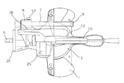
丸鋸部12は、図8に示すようにギヤ16と回転固定された鋸刃軸部15を回転可能に支持し、鋸刃軸部15上に丸鋸刃14を回転固定されるよう取付け可能な構成をしている。また、ギヤ16と噛合うピニオン17aを有するプーリ軸17と、プーリ軸17と回転固定されたプーリ18と、丸鋸刃14の回転軸となる鋸刃軸部15と平行に且つ丸鋸刃14側面の延長線と交差するように配置されたモータ21と、モータ軸22と回転固定されたプーリ23と、プーリ18及びプーリ23に巻き付きモータ軸22の回転力をプーリ18に伝達するための伝達ベルト24とを有している。本発明ベルト機構は伝達ベルト24、プーリ18、23によって構成される。
As shown in FIG. 8, the
丸鋸部12のハウジングは、丸鋸刃14の一部外周を覆うと共に、鋸刃軸部15を覆う形状をしたソーカバー20と、ソーカバー20と連結し、鋸刃軸部15、ギヤ16、プーリ軸17、プーリ18、プーリ23等を覆う形状をしたギヤカバー37と、ギヤカバー28と連結しモータ21、モータ軸22を覆う形状をしたモータハウジング25とから構成される。
The housing of the
ソーカバー20のホルダ5側部分には開口した切粉排出口20aが形成されており(図6)、図1の破線で示す集塵バック41を切粉排出口20aと接続する、あるいは切粉排出口20aに集塵機と接続したホースを接続することで、切断加工時に発生する切粉の飛散を抑制することができる。
An opened chip discharge port 20a is formed in the
なお、最も支持部材8がホルダ5側に位置した際に集塵バック41の後端面が、ガイドバー7の軸方向において最もベース部から離れる部分(図1ではクランプレバー6)よりもベース部側に位置する構成とすることによって、ホルダ5後方に壁や物等の障害物がある状態での作業時においても切断作業に影響をきたすことを抑制することができる。このような構成は、集塵バック41の寸法を考慮することや、集塵バック41が丸鋸刃14の側方に配置されるよう例えば切粉排出口20aが丸鋸刃14に対して角度を持って延びる形状とすることで達成される。
When the
また、ソーカバー20内にはソーカバー20より突出する部分の丸鋸刃14外周を覆う形状をした鋸カバー19が回動可能に設けられている。鋸カバー19は図1に示すように丸鋸部12が上方に揺動している状態では、ソーカバー20より突出する部分の丸鋸刃14外周を覆う位置に回動し、図6に示すように丸鋸部12が下方に揺動している状態では図示しないリンク機構によってソーカバー20内に収納され、ソーカバー20より突出する部分の丸鋸刃14外周を露出する位置に回動する。
In the
モータハウジング25には丸鋸刃14側面の延長線上に位置するハンドル部26が一体的に設けられており、ハンドル部26にはモータ21の駆動を制御するスイッチ27が設けられている。ハンドル部26を丸鋸刃14側面の延長線上に設けることにより、切断加工時(揺動時)に丸鋸刃14を介して丸鋸部12に加わる反力を丸鋸部12に傾き等が起きることなく受けることができる。
The
また、モータハウジング25には丸鋸部12が図6に示すように最もベース部側に近づくように揺動した際に把持部がガイドバー7の軸方向とほぼ平行となる形状をしたサブハンドル36が設けられていると共に、最下方に揺動した状態で支持部材8と丸鋸部12との揺動を固定する図示しない固定手段が設けられている。前記固定手段を動作させ、サブハンドル36を持って持ち運びを行なえば持ち運びが容易に行うことができるようにしている。
Further, the
図2及び図8に示すように、ガイドバー7は丸鋸刃14の側面に対してほぼ平行に配列されている。すなわち、2本のガイドバー7をを結ぶ仮想線が丸鋸刃14側面に対してほぼ平行となるように配置しており、このような構成とすることによって、丸鋸部12の揺動時に支持部材8の摺動部8b、8c及びホルダ5のガイドバー7を固定する部分に加わる荷重に対する剛性を向上させることができると共に、持ち運び時にガイドバー7に加わる荷重に対する剛性を向上させることができるようになる。
As shown in FIGS. 2 and 8, the
また、ガイドバー7は、丸鋸部12がベース部上面から最も離れた上方位置に揺動している状態で、丸鋸刃14の回動軸の延長線と近接する位置に位置し、丸鋸部12がベース部上面に最も近づく下方位置に揺動している状態(図6の状態)ではハンドル26との丸鋸刃14の回動軸方向の距離が小さくなる位置に設けられて、ガイドバー7が工具全体の高さ方向寸法に影響をきたさず小型化を阻害するものではないと共に、丸鋸部12が下方位置にある切断加工時の摺動操作をよりスムーズに行うことができるようになっている。
The
モータ21は上述したように丸鋸刃14側面の延長線と交差する部分を有するよう配置され、丸鋸部12はモータ25の回転力を丸鋸刃14に伝達するためのベルト機構を有する構成となっていることによって、丸鋸部12における丸鋸刃14の軸方向の寸法を小さくすることができるようになり、これによって図4に示すようにガイドレバー7側にホルダ5及び丸鋸部12を傾斜させる構成とすることができ、左右方向に45度傾斜可能な構成となっている。
As described above, the
なお、図2、図4及び図5に示すように、ホルダ5のベース部側部分には傾斜時の位置決め手段であるストッパ5a、5bが設けられ、ターンテーブル2上面にはストッパ5a、5bの移動軌跡上に位置する傾斜微調整手段であるストッパボルト30、31が垂直方向にねじ嵌合している。ホルダ5を傾動軸4を支点として傾斜させると、所定の傾斜角度でストッパ5a、5bがストッパボルト30、31の各々の頭部に当接し、丸鋸部12の傾動位置が位置決めされる。ストッパボルト30は、ホルダ5が左方向に45度の位置に傾斜したときにストッパ5aに係合するように設けられている。また、ストッパボルト31は、ホルダ5が右方向に45度の位置に傾斜したときにストッパ5bに係合するように設けられている。
2, 4, and 5,
更に、ターンテーブル2上部には貫通孔2bが設けられると共に、貫通孔2b内には直角時の位置決め手段となるピン32が前後に水平移動自在に設けられており、図2に示すようにホルダ5にはピン32の移動軌跡上に位置するようにストッパボルト33が垂直方向にねじ嵌合している。ホルダ5が直角切断位置になったとき、ストッパボルト33の先端とピン32の外径部が接触する。
Further, a through
上記した構成において、丸鋸部12を垂直位置に設定し加工材35を直角切断するには、ピン32を前方へ移動させた状態でホルダ5を傾動させ、ストッパボルト33先端とピン32外径部が接触する位置に傾動した際に、クランプレバー6を締めホルダ5の傾動位置を固定することで行なわれる。
In the above-described configuration, in order to set the
被加工材35を切断するには、ハンドル26に設けたスイッチ27を操作し、モータ21を回転駆動させ、のこ刃軸15を介して丸鋸刃14を回転させる。この状態で、ハンドル26を握りスプリング13の付勢力に抗して丸鋸部12を押し下げ、被加工材35を切断する。丸鋸刃14がターンテーブル2の溝部内へ侵入し被加工材35の切断が完了した時点で、丸鋸部12への押し下げ力を解除すると、スプリング13の付勢力によってもとの上限位置に復帰する。角度切りをする場合は、ターンテーブル2を回転し前述した切断方法で加工材35の切断作業を行う。
In order to cut the
次に、丸鋸部12を左右傾斜させる方法について説明する。クランプレバー6を緩めホルダ5の固定状態を解除してホルダ5を傾動軸4を支点として左または右方向へ傾動させる。この時、モータ21の重心はホルダシャフト4のほぼ真上に位置するため、丸鋸部12を左傾斜、右傾斜のどちら側でもほぼ一定の力で傾斜させることができる。クランプレバー6を緩めホルダ5の固定状態を解除してホルダ5を左方向へ傾動させると、ストッパ5aがストッパボルト30に当接し、丸鋸部12は左傾斜45度の状態に位置決めされる。この状態で、クランプレバー6を締めホルダ5の傾斜位置を固定する。あとは前述した切断方法で加工材35の切断作業を行う。
Next, a method for tilting the
更に、直角切り、角度切り、傾斜切りで幅の広い加工材を切断する場合には、フェンス3面に加工材35を押しつけ固定したあと、ノブ10を緩め、ハンドル26で手前側(図1の右方向)に引くと、丸のこ部ホルダ8、及び丸のこ部12は一体となって移動する。
Furthermore, when cutting a wide workpiece by right angle cutting, angle cutting, or inclined cutting, after pressing the workpiece 35 on the
ハンドル26を押し下げ切込みを与えたあと、ホルダ5側に丸鋸部12を摺動させながら切断を行う(図6の状態)。切断終了後、丸鋸部12への押し下げ力を解除すると、スプリング13の付勢力によってもとの上限位置に復帰する。
After the
上記したように、スライド、直角、角度、傾斜切り、また、前述した角度切りの切断方法と傾斜切りの方法を組み合わせた複合切断が可能である。 As described above, slide, right angle, angle, inclined cutting, and combined cutting that combines the above-described angle cutting and inclined cutting methods are possible.
次に、本発明卓上丸鋸の他の実施形態を図9及び図10に示す。本実施形態は上記実施形態の傾動規制手段の構成を改良したものであり、他の部分については上記実施形態と同一であるので説明を省略する。 Next, another embodiment of the tabletop circular saw of the present invention is shown in FIGS. This embodiment is an improvement of the configuration of the tilt restricting means of the above embodiment, and the other parts are the same as those of the above embodiment, and the description thereof is omitted.
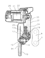
図に示すように、ターンテーブル2のホルダ5側端面には上方に突出する上端面が円弧形状をした突出部2aが形成されており、突出部2aの一部分はホルダ5の後端面とホルダ5に設けられた突部28とによって覆われている。傾動軸4の軸方向において突出部2aと突部28との間には移動部材であるスライダー29が配置されている。
As shown in the figure, a projecting
突部28には図に示すように傾動軸4の軸心延長線上にほぼ向うように、すなわち傾動軸4の径方向に延びた貫通穴28bが形成されており、貫通穴28b内にはクランプボルト6が回動可能に位置して、クランプボルト6にはスライダー29が螺合している。図に示すスライダー29の上端面と突部28の下端との間には、クランプボルト6の外周に配置された付勢手段であるバネ34が配置されており、スライダー29はバネ34によって常に傾動軸4側に付勢されている。
As shown in the figure, the
突部28のホルダ5後端面及び突出部2aと対向する個所には、傾動軸4側(図示下方)に向うに従ってホルダ5後端面及び突出部2aから離れるように傾斜したテーパー部28aが設けられている。また、図に示すようにスライダー29にもテーパー部28aと面接触可能なようにテーパー部28aとほぼ同様の傾斜角度で形成されたテーパー部29aが形成されている。
A tapered portion 28a that is inclined away from the rear end surface of the
図9に示す状態は、ターンテーブル2に対してホルダ5の傾動が固定されている状態であるが、図に示す状態では、ターンテーブル2の突出部2aはホルダ5後端面とスライダー29によって傾動軸4の軸方向に挟持され、相対回動不能な状態となっている。詳細には、スライダー29のテーパー部29aと突部28のテーパー部28aとは当接状態にあると共に、バネ34は軸方向に圧縮された状態、クランプボルト6は締め付け状態にあり、スライダー29は突部28と突出部2aとの間に入り込んだ状態にある。
The state shown in FIG. 9 is a state in which the tilt of the
この状態から丸鋸部12を左右方向に傾斜させるには、まずクランプボルト6を緩める。
In order to incline the
この緩め作業によってバネ34の付勢力及び自身の重力によってスライダー29は傾動軸4側(図1の下方)に移動する。
By this loosening operation, the
上記したスライダー29の移動によってスライダー29とホルダ5後端面とによる突出部2aの挟持は解除され、ターンテーブル2に対するホルダ5の傾動が可能となる。
By the movement of the
その後、丸鋸部12を把持する等してターンテーブル2に対してホルダ5を任意の角度に傾動させ、傾動位置を保持した状態で再度クランプボルト6を締め付け操作することで、スライダー29がバネ34の付勢力に抗しながらクランプボルト6の軸方向に移動し、両テーパー部28a、29aが接触し、更にスライダー29がクランプボルト6の軸方向に移動することでスライダー29がホルダ5側に突出部2aを押圧するため、突出部2aがスライダー29とホルダ5とで挟持され、ターンテーブル2に対するホルダ5の傾動を固定し丸鋸部12の傾動位置を固定することができる。
Thereafter, the
なお、スライダー29が突出部2aとテーパー面28aとの間に比較的強固に食い込んだ状態となり、クランプボルト6を緩めたとしてもバネ34の付勢力及び自身の重力によって傾動軸4側(図示下方)に移動しなかった場合においても、緩め操作によって上方に突出したクランプボルト6を下方に押し下げればスライダー29を傾動軸4側に移動させ、ターンテーブル2に対してホルダ5を傾動可能な状態とすることができる。
It should be noted that the
また、ホルダ5の傾動固定は、上記したようにスライダー29がクランプボルト6の軸方向に移動することにより行なわれるが、詳細には、スライダー29はクランプボルト6と貫通穴28b間の隙間によって突出部2a側へも移動するものである。また、ホルダ5の後端面と突出部2aとの間に僅かな隙間がある場合には、この隙間が無くなるようにホルダ5が移動や傾くことによりスライダー29とホルダ5後端面とで突出部2aが挟持される。
The
上述したようにホルダ5の傾動固定を解除することで、ホルダ5を傾動軸4を支点として左または右方向へ傾動させることができるものであるが、モータ21の重心はホルダシャフト4のほぼ真上に位置するため、丸鋸部12を左傾斜、右傾斜のどちら側でもほぼ一定の力で傾斜させることができる。クランプボルト6を緩めホルダ5の固定状態を解除してホルダ5を左方向へ傾動させると、ストッパ5aがストッパボルト30に当接し、丸鋸部12は左傾斜45度の状態に位置決めされる。この状態で、クランプボルト6を締めホルダ5の傾斜位置を固定した後には、前述した切断方法で加工材35の切断作業を行うことができる。
As described above, by releasing the tilt fixing of the
上記したような構成とすることによって、傾動作業時にホルダ5後方側に手を回り込ます必要がなく、ホルダ5後方に壁や物等がある場合であっても傾動作業を行うことができ、且つ傾動作業時に本体側方後方側に位置せずとも操作部材6に手が届き、傾動作業の操作性を良くすることができる。また、卓上切断機本体を配置させる際には、ホルダ5及び操作部材後方のスペースを考慮する必要が無く、作業スペースを小型化することができるものである。
By adopting the configuration as described above, it is not necessary to wrap the hand to the rear side of the
なお、上記実施形態ではガイドバー7を2本で構成したが、1本あるいは3本であっても良い。
In the above embodiment, the
また、上記実施形態では左右両傾斜の構成としたが片傾斜の構成としても良いものであると共に、上記実施形態では、丸鋸刃14の右側に動力を伝達するギヤ16やプーリ18、23及びガイドバー7を配置させたが、上記実施形態と逆の左側に各部材を配置した構成としても、良いものである。更には、ベース部がターンテーブル2を有さないベース1のみの構成であっても良い。
In the above-described embodiment, the left and right inclined structures may be used. However, in the above-described embodiment, the
1はベース、2はターンテーブル、3はフェンス、4は傾動軸、5はホルダ、6はクランプレバー、7はガイドバー、8は支持部材、8aは穴部、8bはボールベアリング、8cは移動部材、8dはボルト、9はサポート、10はノブ、11は揺動軸、12は丸鋸部、13はスプリング、14は丸鋸刃である。 1 is a base, 2 is a turntable, 3 is a fence, 4 is a tilting shaft, 5 is a holder, 6 is a clamp lever, 7 is a guide bar, 8 is a support member, 8a is a hole, 8b is a ball bearing, 8c is moving A member, 8d is a bolt, 9 is a support, 10 is a knob, 11 is a swing shaft, 12 is a circular saw part, 13 is a spring, and 14 is a circular saw blade.
Claims (11)
前記丸鋸刃の軸方向にほぼ直交すると共に前記ベース部上面に対してほぼ平行に延びる傾動軸により前記ベース部に対して傾動可能なホルダと、前記ベース部に対する前記ホルダの傾動を規制する傾動規制手段と、前記ホルダに固定され、前記傾動軸とほぼ平行に延びるガイドバーを有するガイド部とを設け、前記支持部材を前記ガイド部上で摺動・固定可能な構成としたことを特徴とする卓上切断機。 A base portion on which a workpiece can be placed, a circular saw portion that houses an electric motor and rotatably supports a circular saw blade that rotates by driving of the electric motor, and substantially parallel to the axial direction of the circular saw blade A tabletop cutting machine having a support member for swingably supporting the circular saw portion by a swing shaft, and capable of changing an angle of the side surface of the circular saw blade with respect to the upper surface of the base portion,
A holder that can be tilted with respect to the base portion by a tilting shaft that is substantially orthogonal to the axial direction of the circular saw blade and that extends substantially parallel to the upper surface of the base portion, and tilting that restricts tilting of the holder with respect to the base portion. A regulation unit and a guide part having a guide bar fixed to the holder and extending substantially parallel to the tilting shaft are provided, and the support member can be slid and fixed on the guide part. Desktop cutting machine.
Priority Applications (8)
| Application Number | Priority Date | Filing Date | Title |
|---|---|---|---|
| JP2004092737A JP2005279933A (en) | 2004-03-26 | 2004-03-26 | Bench cutter |
| US11/078,489 US8061250B2 (en) | 2004-03-26 | 2005-03-14 | Miter saw having circular saw blade section pivotally movable upward and downward and tiltable leftward and rightward |
| DE200560002966 DE602005002966T2 (en) | 2004-03-26 | 2005-03-22 | Miter saw with circular saw blade cut, which can be tilted from top to bottom and tilted from right to left |
| EP20050251734 EP1579938B1 (en) | 2004-03-26 | 2005-03-22 | Miter saw having circular saw blade section pivotally movable upward and downward and tiltable leftward and rightward |
| ES05251734T ES2296096T3 (en) | 2004-03-26 | 2005-03-22 | SAWING MACHINE WITH A PIVOT CIRCULAR SAW BLADE SECTION UP AND DOWN AND SWING TO THE LEFT AND RIGHT. |
| AT05251734T ATE376470T1 (en) | 2004-03-26 | 2005-03-22 | COMPUTING OR MITER SAW THAT CAN SWIVEL UP AND DOWN AND TILT TO THE RIGHT AND LEFT |
| CNB2005100560926A CN100445005C (en) | 2004-03-26 | 2005-03-23 | Miter saw having circular saw blade section pivotally movable upward and downward and tiltable leftward and rightward |
| TW94109283A TWI291388B (en) | 2004-03-26 | 2005-03-25 | Miter saw |
Applications Claiming Priority (1)
| Application Number | Priority Date | Filing Date | Title |
|---|---|---|---|
| JP2004092737A JP2005279933A (en) | 2004-03-26 | 2004-03-26 | Bench cutter |
Related Child Applications (1)
| Application Number | Title | Priority Date | Filing Date |
|---|---|---|---|
| JP2009219863A Division JP5107325B2 (en) | 2009-09-25 | 2009-09-25 | Tabletop cutting machine |
Publications (2)
| Publication Number | Publication Date |
|---|---|
| JP2005279933A true JP2005279933A (en) | 2005-10-13 |
| JP2005279933A5 JP2005279933A5 (en) | 2009-11-05 |
Family
ID=34858513
Family Applications (1)
| Application Number | Title | Priority Date | Filing Date |
|---|---|---|---|
| JP2004092737A Pending JP2005279933A (en) | 2004-03-26 | 2004-03-26 | Bench cutter |
Country Status (8)
| Country | Link |
|---|---|
| US (1) | US8061250B2 (en) |
| EP (1) | EP1579938B1 (en) |
| JP (1) | JP2005279933A (en) |
| CN (1) | CN100445005C (en) |
| AT (1) | ATE376470T1 (en) |
| DE (1) | DE602005002966T2 (en) |
| ES (1) | ES2296096T3 (en) |
| TW (1) | TWI291388B (en) |
Cited By (7)
| Publication number | Priority date | Publication date | Assignee | Title |
|---|---|---|---|---|
| JP2005279934A (en) * | 2004-03-26 | 2005-10-13 | Hitachi Koki Co Ltd | Bench cutter |
| WO2007099884A1 (en) * | 2006-02-22 | 2007-09-07 | Hitachi Koki Co., Ltd. | Miter saw |
| JP2007237544A (en) * | 2006-03-08 | 2007-09-20 | Hitachi Koki Co Ltd | Bench cutting machine |
| WO2010087246A1 (en) | 2009-01-30 | 2010-08-05 | 株式会社マキタ | Table-top cutting machine |
| JP2010274390A (en) * | 2009-05-29 | 2010-12-09 | Hitachi Koki Co Ltd | Bench cutter |
| JP2012115946A (en) * | 2010-11-30 | 2012-06-21 | Hitachi Koki Co Ltd | Desktop cutter |
| JP2020146778A (en) * | 2019-03-12 | 2020-09-17 | 育良精機株式会社 | Cutting device |
Families Citing this family (21)
| Publication number | Priority date | Publication date | Assignee | Title |
|---|---|---|---|---|
| JP4759276B2 (en) * | 2005-01-20 | 2011-08-31 | 日立工機株式会社 | Tabletop cutting machine |
| CN201143573Y (en) * | 2007-05-08 | 2008-11-05 | 南京德朔实业有限公司 | Miter saw |
| JP5056318B2 (en) * | 2007-09-28 | 2012-10-24 | 日立工機株式会社 | Tabletop cutting machine |
| CN101612674A (en) * | 2008-06-23 | 2009-12-30 | 苏州宝时得电动工具有限公司 | Diagonal cutting saw |
| DE202008011654U1 (en) * | 2008-09-02 | 2010-01-21 | Metabowerke Gmbh | Chop saw with pull function |
| EP2379291A4 (en) * | 2008-12-17 | 2012-12-19 | Bosch Power Tools China Co Ltd | Circular saw with anti-splinter device |
| US8919235B2 (en) * | 2009-03-17 | 2014-12-30 | Hitachi Koki Co., Ltd. | Cutting apparatus |
| JP5530649B2 (en) * | 2009-03-26 | 2014-06-25 | 株式会社マキタ | Slide marnoco |
| CN102756173B (en) * | 2011-04-29 | 2014-04-02 | 苏州宝时得电动工具有限公司 | Oblique cutting saw |
| JP5835611B2 (en) * | 2011-11-29 | 2015-12-24 | 日立工機株式会社 | Sliding tabletop cutting machine |
| US9649703B2 (en) | 2012-03-15 | 2017-05-16 | Rexon Industrial Corp., Ltd. | Circular saw with a moving mechanism |
| TWI491459B (en) * | 2012-03-15 | 2015-07-11 | Rexon Ind Corp Ltd | A circular saw with a moving mechanism |
| CN104511653B (en) * | 2013-09-30 | 2017-10-17 | 苏州宝时得电动工具有限公司 | Cutting machine |
| JP6249214B2 (en) * | 2013-12-19 | 2017-12-20 | パナソニックIpマネジメント株式会社 | Electric circular saw |
| CN104476622B (en) * | 2014-11-26 | 2016-05-11 | 嘉善睿逸电子科技有限公司 | A kind of table sawing machine |
| DE102018125423B4 (en) * | 2018-10-15 | 2020-11-05 | Metabowerke Gmbh | Machine tool system |
| TWD202486S (en) | 2019-02-19 | 2020-02-01 | 吳榮哲 | Part of cutting machine |
| TWD206004S (en) | 2019-02-19 | 2020-07-21 | 吳榮哲 | Part of the cutting machine |
| CN110000607B (en) * | 2019-04-23 | 2021-08-13 | 南京昱晟机器人科技有限公司 | Cutting equipment for anti-theft fire-resistant clamping plate |
| US20220168828A1 (en) | 2020-12-02 | 2022-06-02 | Makita Corporation | Sliding cutting machine |
| JP2023102452A (en) | 2022-01-12 | 2023-07-25 | 株式会社マキタ | Cutting machine on bench |
Citations (5)
| Publication number | Priority date | Publication date | Assignee | Title |
|---|---|---|---|---|
| US4537105A (en) * | 1983-08-16 | 1985-08-27 | Black & Decker Overseas Ag | Circular cross-cut and miter saw box |
| JPH09164504A (en) * | 1995-08-10 | 1997-06-24 | Milwaukee Electric Tool Corp | Support assembly for slide double miter saw |
| JPH11170202A (en) * | 1997-12-12 | 1999-06-29 | Hitachi Koki Co Ltd | Slide type table cutting |
| JP2000225603A (en) * | 1999-02-05 | 2000-08-15 | Hitachi Koki Co Ltd | Cutting positioning apparatus for cutting machine |
| CA2372451A1 (en) * | 2002-02-19 | 2003-08-19 | Gerald John Williams | Compact sliding compound mitre saw |
Family Cites Families (22)
| Publication number | Priority date | Publication date | Assignee | Title |
|---|---|---|---|---|
| JPH067859Y2 (en) | 1985-07-05 | 1994-03-02 | 株式会社日立工機原町 | Sliding tabletop cutting machine |
| JPH0624161Y2 (en) * | 1990-06-29 | 1994-06-29 | リョービ株式会社 | Table slide circular saw machine |
| DE4106636C1 (en) * | 1991-02-28 | 1992-06-04 | Black & Decker Inc., Newark, Del., Us | |
| DE4106635C1 (en) | 1991-02-28 | 1992-07-23 | Black & Decker Inc., Newark, Del., Us | |
| JP2613156B2 (en) * | 1992-08-27 | 1997-05-21 | 株式会社マキタ | Tabletop circular saw machine |
| US5425294A (en) * | 1993-06-03 | 1995-06-20 | Hitachi Koki Haramachi Co., Ltd. | Desk-top cutting machine with tiltable saw |
| JP3431347B2 (en) * | 1995-06-05 | 2003-07-28 | 株式会社マキタ | Tabletop circular saw machine |
| US5862732A (en) * | 1996-07-30 | 1999-01-26 | Milwaukee Electric Tool Corporation | Support assembly for a slide compound miter saw |
| US5819624A (en) * | 1996-07-30 | 1998-10-13 | Milwaukee Electric Tool Corporation | Indexing override mechanism for a slide compound miter saw |
| JP3331105B2 (en) * | 1995-10-05 | 2002-10-07 | 株式会社マキタ | Marunoko tilt stopper device |
| US5957021A (en) * | 1995-10-10 | 1999-09-28 | Black & Decker, Inc. | Guard and control apparatuses for sliding compound miter saw |
| US5870938A (en) | 1995-12-12 | 1999-02-16 | Black & Decker Inc. | Bevel locking system for a sliding compound miter saw |
| US5907987A (en) * | 1996-12-05 | 1999-06-01 | Stumpf; William R. | Bevel locking system for a sliding compound miter saw |
| JP3549732B2 (en) | 1997-07-23 | 2004-08-04 | 株式会社マキタ | Stopper device for slide mechanism |
| JP2001300902A (en) | 2000-04-21 | 2001-10-30 | Hitachi Koki Co Ltd | Apparatus for removing chip of cutter with laser oscillator |
| US6918330B2 (en) * | 2000-10-24 | 2005-07-19 | Thomson Industries, Inc. | Adjustable tool station |
| US7387056B2 (en) * | 2002-06-07 | 2008-06-17 | Makita Corporation | Slide compound saws |
| TW569907U (en) * | 2002-09-26 | 2004-01-01 | P & F Brother Ind Corp | Dust collecting structure for supporting seat of cutting machine |
| US20040089125A1 (en) * | 2002-11-08 | 2004-05-13 | Emerson Electric Co. | Compound miter saw |
| CN2691757Y (en) | 2004-01-08 | 2005-04-13 | 宁波经济技术开发区中强电动工具有限公司 | Sliding sleeve type bias cutter |
| TWI224544B (en) * | 2004-03-08 | 2004-12-01 | P & F Brother Ind Corp | Multi-direction adjustable laser marking device for cutting machine |
| DE202004004929U1 (en) | 2004-03-26 | 2004-06-09 | Lutz Gmbh Maschinenbau | Cross=cut or mitre saw, has sawblade arm pivotally connected to holder part which can be slid along guide |
-
2004
- 2004-03-26 JP JP2004092737A patent/JP2005279933A/en active Pending
-
2005
- 2005-03-14 US US11/078,489 patent/US8061250B2/en not_active Expired - Fee Related
- 2005-03-22 EP EP20050251734 patent/EP1579938B1/en active Active
- 2005-03-22 ES ES05251734T patent/ES2296096T3/en active Active
- 2005-03-22 AT AT05251734T patent/ATE376470T1/en not_active IP Right Cessation
- 2005-03-22 DE DE200560002966 patent/DE602005002966T2/en active Active
- 2005-03-23 CN CNB2005100560926A patent/CN100445005C/en not_active Expired - Fee Related
- 2005-03-25 TW TW94109283A patent/TWI291388B/en not_active IP Right Cessation
Patent Citations (5)
| Publication number | Priority date | Publication date | Assignee | Title |
|---|---|---|---|---|
| US4537105A (en) * | 1983-08-16 | 1985-08-27 | Black & Decker Overseas Ag | Circular cross-cut and miter saw box |
| JPH09164504A (en) * | 1995-08-10 | 1997-06-24 | Milwaukee Electric Tool Corp | Support assembly for slide double miter saw |
| JPH11170202A (en) * | 1997-12-12 | 1999-06-29 | Hitachi Koki Co Ltd | Slide type table cutting |
| JP2000225603A (en) * | 1999-02-05 | 2000-08-15 | Hitachi Koki Co Ltd | Cutting positioning apparatus for cutting machine |
| CA2372451A1 (en) * | 2002-02-19 | 2003-08-19 | Gerald John Williams | Compact sliding compound mitre saw |
Cited By (12)
| Publication number | Priority date | Publication date | Assignee | Title |
|---|---|---|---|---|
| JP2005279934A (en) * | 2004-03-26 | 2005-10-13 | Hitachi Koki Co Ltd | Bench cutter |
| JP4534549B2 (en) * | 2004-03-26 | 2010-09-01 | 日立工機株式会社 | Tabletop cutting machine |
| WO2007099884A1 (en) * | 2006-02-22 | 2007-09-07 | Hitachi Koki Co., Ltd. | Miter saw |
| US8127650B2 (en) | 2006-02-22 | 2012-03-06 | Hitachi Koki Co., Ltd. | Miter saw |
| JP2007237544A (en) * | 2006-03-08 | 2007-09-20 | Hitachi Koki Co Ltd | Bench cutting machine |
| JP4552873B2 (en) * | 2006-03-08 | 2010-09-29 | 日立工機株式会社 | Tabletop cutting machine |
| US7845260B2 (en) | 2006-03-08 | 2010-12-07 | Hitachi Koki Co., Ltd. | Miter saw |
| WO2010087246A1 (en) | 2009-01-30 | 2010-08-05 | 株式会社マキタ | Table-top cutting machine |
| JP2010274390A (en) * | 2009-05-29 | 2010-12-09 | Hitachi Koki Co Ltd | Bench cutter |
| JP2012115946A (en) * | 2010-11-30 | 2012-06-21 | Hitachi Koki Co Ltd | Desktop cutter |
| JP2020146778A (en) * | 2019-03-12 | 2020-09-17 | 育良精機株式会社 | Cutting device |
| JP7104417B2 (en) | 2019-03-12 | 2022-07-21 | 育良精機株式会社 | Cutting device |
Also Published As
| Publication number | Publication date |
|---|---|
| EP1579938A2 (en) | 2005-09-28 |
| ATE376470T1 (en) | 2007-11-15 |
| US20050235791A1 (en) | 2005-10-27 |
| CN100445005C (en) | 2008-12-24 |
| CN1672844A (en) | 2005-09-28 |
| EP1579938A3 (en) | 2006-01-18 |
| TW200600238A (en) | 2006-01-01 |
| US8061250B2 (en) | 2011-11-22 |
| ES2296096T3 (en) | 2008-04-16 |
| TWI291388B (en) | 2007-12-21 |
| EP1579938B1 (en) | 2007-10-24 |
| DE602005002966D1 (en) | 2007-12-06 |
| DE602005002966T2 (en) | 2008-08-07 |
Similar Documents
| Publication | Publication Date | Title |
|---|---|---|
| JP2005279933A (en) | Bench cutter | |
| JP4534549B2 (en) | Tabletop cutting machine | |
| US7387058B2 (en) | Miter saw having light beam projection device | |
| JP2006327088A (en) | Bench disc saw | |
| JP2003145501A (en) | Laterally inclining type desk cutter | |
| JP5107325B2 (en) | Tabletop cutting machine | |
| JP5391840B2 (en) | Tabletop cutting machine | |
| JP3698954B2 (en) | Portable power cutting machine | |
| JP4847098B2 (en) | Cutting machine | |
| JP4827160B2 (en) | Tabletop cutting machine | |
| JP6274522B2 (en) | Cutting machine | |
| JP5105210B2 (en) | Tabletop cutting machine | |
| JP4483488B2 (en) | Tabletop cutting machine | |
| JP4715786B2 (en) | Tabletop cutting machine | |
| JP2008100356A (en) | Slide type bench cutter | |
| JP2012176492A (en) | Table top cutter | |
| JP2013031924A (en) | Desktop cutter | |
| JP2004142105A (en) | Inclined stopper device for cutting machine | |
| JP5760602B2 (en) | Sliding tabletop cutting machine | |
| JP2619826B2 (en) | Tabletop circular saw machine | |
| JP2008100355A (en) | Slide type bench cutter | |
| JP2008229880A (en) | Bench cutter | |
| JPH11170214A (en) | Chip guiding device for slide type table cutter | |
| JP3345205B2 (en) | Left and right tilt type saw device | |
| JP2016221624A (en) | Bench cutting machine |
Legal Events
| Date | Code | Title | Description |
|---|---|---|---|
| A621 | Written request for application examination |
Free format text: JAPANESE INTERMEDIATE CODE: A621 Effective date: 20070326 |
|
| A521 | Request for written amendment filed |
Free format text: JAPANESE INTERMEDIATE CODE: A523 Effective date: 20090916 |
|
| A871 | Explanation of circumstances concerning accelerated examination |
Free format text: JAPANESE INTERMEDIATE CODE: A871 Effective date: 20090916 |
|
| RD02 | Notification of acceptance of power of attorney |
Free format text: JAPANESE INTERMEDIATE CODE: A7422 Effective date: 20090916 |
|
| A977 | Report on retrieval |
Free format text: JAPANESE INTERMEDIATE CODE: A971007 Effective date: 20091002 |
|
| A975 | Report on accelerated examination |
Free format text: JAPANESE INTERMEDIATE CODE: A971005 Effective date: 20091006 |
|
| A131 | Notification of reasons for refusal |
Free format text: JAPANESE INTERMEDIATE CODE: A131 Effective date: 20091009 |
|
| A521 | Request for written amendment filed |
Free format text: JAPANESE INTERMEDIATE CODE: A523 Effective date: 20091109 |
|
| A02 | Decision of refusal |
Free format text: JAPANESE INTERMEDIATE CODE: A02 Effective date: 20091208 |