JP2012114371A - Substrate storage container - Google Patents
Substrate storage container Download PDFInfo
- Publication number
- JP2012114371A JP2012114371A JP2010264167A JP2010264167A JP2012114371A JP 2012114371 A JP2012114371 A JP 2012114371A JP 2010264167 A JP2010264167 A JP 2010264167A JP 2010264167 A JP2010264167 A JP 2010264167A JP 2012114371 A JP2012114371 A JP 2012114371A
- Authority
- JP
- Japan
- Prior art keywords
- hole
- storage container
- substrate storage
- bottom plate
- identification
- Prior art date
- Legal status (The legal status is an assumption and is not a legal conclusion. Google has not performed a legal analysis and makes no representation as to the accuracy of the status listed.)
- Pending
Links
Images


Abstract
Description
本発明は基板収納容器に係り、特に、たとえば半導体ウェーハなどの基板を収納して用いられ、半導体生産工程で、該基板に各種の処理・加工の際に、該基板を搬送・保管する基板収納容器に関する。 The present invention relates to a substrate storage container, and in particular, a substrate storage that is used by storing a substrate such as a semiconductor wafer, and that transports and stores the substrate during various processing and processing in the semiconductor production process. Concerning the container.
この種の基板収納容器として、正面に開口部を有する容器本体と、この容器本体の開口部をシール可能に閉鎖する蓋体とを備えて構成されたものが知られている。容器本体には、その内壁面に対向して配置された一対の支持部を備え、これら支持部に垂直方向に沿って並設された各溝に、基板の周辺の一部を支持させることにより、該基板を水平状態にして容器本体内に収納するようになっている。 As this type of substrate storage container, there is known a container configured to include a container main body having an opening on the front surface and a lid for closing the opening of the container main body so as to be sealable. The container body is provided with a pair of support portions disposed so as to face the inner wall surface, and by supporting a part of the periphery of the substrate in each groove arranged in parallel along the vertical direction with these support portions. The substrate is stored in the container body in a horizontal state.
このような基板収納容器は、その天面にロボテックフランジが取り付けられ、このロボテックフランジを介して工場内に設置されたレールに沿って搬送できるようになっている。 Such a substrate storage container has a robotic flange attached to the top surface thereof, and can be transported along a rail installed in the factory via the robotic flange.
また、基板収納容器の底面にはボトムプレートが設けられており、このボトムプレートによって、基板収納容器を、コンベア搬送したり、各加工装置の設置個所において基板収納容器のセンシング(識別)、位置決め、あるいは固定したりできるようになっている。 In addition, a bottom plate is provided on the bottom surface of the substrate storage container. With this bottom plate, the substrate storage container is conveyed by conveyor, and sensing (identification), positioning, and positioning of the substrate storage container at each processing apparatus installation location. Or it can be fixed.
このことから、ボトムプレートには、少なくとも、1対のコンベアレールと、識別部材の取り付けがなされる個所(識別領域)と、基板収納容器の位置決めのためのガイド部材と、基板収納容器の加工装置等への固定を行うための固定部とが設けられている。 Therefore, the bottom plate includes at least a pair of conveyor rails, a location (identification area) where the identification member is attached, a guide member for positioning the substrate storage container, and a substrate storage container processing apparatus. And a fixing portion for fixing to the like.
そして、ボトムプレートの識別部材の取り付けがなされる領域には、複数の貫通孔が設けられ、これら貫通孔に識別部材となるプラグを選択的に取り付けることによって該貫通孔を閉塞させるようになっている。すなわち、貫通孔のプラグによる選択的な閉塞によって、貫通孔の有り無しの状態を基板収納容器の仕様に対応させるようにしている。加工装置側では、これらの貫通孔の有り無しの状態をセンシングすることにより、基板収納容器の仕様を確認することができるようになっている(特許文献1、2参照)。 And in the area | region where the identification member of the bottom plate is attached, a plurality of through holes are provided, and the through holes are closed by selectively attaching plugs serving as identification members to these through holes. Yes. That is, by selectively closing the through hole with the plug, the presence or absence of the through hole is made to correspond to the specification of the substrate storage container. On the processing apparatus side, the specifications of the substrate storage container can be confirmed by sensing the presence or absence of these through holes (see Patent Documents 1 and 2).
しかしながら、上述した基板収納容器において、たとえば直径300mmの半導体ウェーハを収納して半導体部品の生産工場で使用されていた基板収納容器のボトムプレートには、識別領域として左右に2箇所ずつ合計4つの位置に識別部材を設けることが、SEMI規格 E47.1等によって定められている。ここで、作業員が基板収納容器を持ち上げたりする際に、基板収納容器の底部を持ち上げたり、点検したりすることがあるが、その際に誤ってボトムプレートと識別部材の間に入れた指が、識別部材に触れてしまい、識別部材を外してしまう不都合があった。 However, in the above-described substrate storage container, for example, the bottom plate of the substrate storage container that stores a semiconductor wafer having a diameter of 300 mm and is used in a semiconductor component production factory has a total of four positions, two on the left and right sides as identification regions. The provision of the identification member is defined by SEMI standard E47.1. Here, when an operator lifts the substrate storage container, the bottom of the substrate storage container may be lifted or inspected. At this time, a finger accidentally placed between the bottom plate and the identification member may be used. However, there is a problem that the identification member is touched and the identification member is removed.
また、昨今、半導体部品の生産工場においてより細かな管理を行うため、識別部位の個数を増やして運用することが検討されている。例えば、次世代の半導体ウェーハとして検討されている直径450mmの半導体ウェーハを収納するための基板収納容器として、左右の識別領域に4箇所ずつの貫通穴を間隔狭く並べて配置することが提案されている。これにより、基板収納容器の仕様を従来の16倍(28/24 =16)に増大させるようにできる。しかし、このようにした場合、間隔を狭めて形成した貫通孔のそれぞれに識別部材を取り付けた場合、周囲に充分なスペースがないために、その後に該識別部材を取り外す際に、その取り外しが困難になってしまうことが懸念される。 Recently, in order to perform finer management in a semiconductor component production factory, it has been studied to increase the number of identification parts. For example, as a substrate storage container for storing a semiconductor wafer having a diameter of 450 mm, which is being considered as a next-generation semiconductor wafer, it has been proposed to arrange four through holes with a narrow interval in the left and right identification regions. . This allows to increase the specifications of substrate storage container to the conventional 16-fold (2 8/2 4 = 16). However, in this case, when the identification member is attached to each of the through holes formed with a narrow interval, there is not enough space around, so that it is difficult to remove the identification member after that. There is a concern that it will become.
さらに、基板収納容器は、その正面側に蓋体を備え、蓋体には容器本体との施錠を行う施錠機構が内蔵されているために、基板収納容器の重心位置が収納させている基板の中心から正面側に偏心することになる。このような偏心は、基板収納容器を高速搬送するときなどに揺れが大きくなって安定な搬送ができないといった弊害をもたらす。このため、ボトムプレートには、基板収納容器の重心位置を調整するカウンターウェイト(重量調整用カウンター)をリア側(蓋体を備える正面側と反対側)に設けることが検討されている。しかし、このカウンターウェイトを設ける位置が識別領域の近傍になってしまうことが免れず、識別部材を貫通孔から取り外すことをさらに困難にさせてしまう不都合が生じる。 Further, the substrate storage container includes a lid on the front side thereof, and the lid includes a locking mechanism that locks the container main body. Therefore, the center of gravity of the substrate storage container is stored. It will be eccentric from the center to the front side. Such eccentricity brings about a bad effect that, when the substrate storage container is transported at a high speed, the shaking becomes large and stable transport cannot be performed. For this reason, it has been considered that the bottom plate is provided with a counterweight (weight adjustment counter) for adjusting the center of gravity of the substrate storage container on the rear side (the side opposite to the front side including the lid). However, it is inevitable that the position where the counterweight is provided is in the vicinity of the identification region, and there arises a problem that it becomes more difficult to remove the identification member from the through hole.
本発明の目的は、識別部材が示す情報の変更を極めて容易に行うことができる基板収納容器を提供することにある。 The objective of this invention is providing the board | substrate storage container which can change the information which an identification member shows very easily.
本発明の目的は、たとえ近傍に重量調整用カウンターが配置されていても、識別部材が示す情報の変更を極めて容易に行うことができる基板収納容器を提供することにある。 An object of the present invention is to provide a substrate storage container in which information indicated by an identification member can be changed very easily even if a weight adjustment counter is disposed in the vicinity thereof.
本発明は、上記課題を解決するために、識別部材が示す情報の変更をたとえば簡易な構成からなる冶具を用いて行うようにしたものである。 In order to solve the above-described problems, the present invention changes the information indicated by the identification member using, for example, a jig having a simple configuration.
本発明は、以下に示す構成によって把握することができる。
(1)本発明の基板収納容器は、開口を有し前記開口を通して基板を収納させる容器本体と、この容器本体の前記開口を閉鎖する蓋体と、前記容器本体の底部に取り付けられるボトムプレートを備える基板収納容器であって、前記ボトムプレートの識別領域に、貫通孔の開閉を行い、あるいは貫通孔に沿ってスライドする識別部材を備え、前記識別部材は、冶具を用いて貫通孔から取り外すようにし、あるいはスライドできるようにしたことを特徴とする。
(2)本発明の基板収納容器は、(1)を前提に、前記ボトムプレートには、前記識別領域が前記蓋体と反対側に形成され、この識別領域に近接して重心調整用カウンターが配置されていることを特徴とする。
This invention can be grasped | ascertained by the structure shown below.
(1) A substrate storage container according to the present invention includes: a container main body having an opening for storing a substrate through the opening; a lid for closing the opening of the container main body; and a bottom plate attached to the bottom of the container main body. The substrate storage container includes an identification member that opens and closes the through hole or slides along the through hole in the identification region of the bottom plate, and the identification member is removed from the through hole using a jig. Or it can slide.
(2) In the substrate storage container of the present invention, on the premise of (1), the identification region is formed on the bottom plate on the side opposite to the lid, and a barycentric adjustment counter is provided adjacent to the identification region. It is arranged.
(3)本発明の基板収納容器は、(1)を前提に、ボトムプレートの識別領域に、複数の第1貫通孔が形成されているとともに、これら第1貫通孔のうち選択された第1貫通孔に着脱可能に取り付けられる識別部材を備え、複数の前記第1貫通孔のそれぞれに近接して配置された第2貫通孔が形成され、前記第1貫通孔に取り付けられている識別部材は前記第2貫通孔を通した冶具によって取り外せるようになっていることを特徴とする。
(4)本発明の基板収納容器は、(3)を前提に、前記第2貫通孔は、その形状がスリット状となっていることを特徴とする。
(5)本発明の基板収納容器は、(3)を前提に、複数からなる第1貫通孔は並設されて形成され、その両端の各第1貫通孔に近接して邪魔板が設けられていることを特徴とする。
(3) In the substrate storage container of the present invention, on the premise of (1), a plurality of first through holes are formed in the identification region of the bottom plate, and the first selected among these first through holes An identification member that is detachably attached to the through hole, has a second through hole disposed adjacent to each of the plurality of first through holes, and the identification member attached to the first through hole is The second through-hole can be removed by a jig.
(4) The substrate storage container of the present invention is characterized in that the shape of the second through hole is slit-like on the premise of (3).
(5) On the premise of (3), the substrate storage container of the present invention is formed by arranging a plurality of first through holes in parallel, and baffle plates are provided adjacent to the first through holes at both ends thereof. It is characterized by.
このような構成からなる基板収納容器によれば、識別部材が示す情報の変更を極めて容易に行うことができるようになる。また、たとえ近傍に重量調整用カウンターが配置されていても、識別部材が示す情報の変更を極めて容易に行うことができるようになる。 According to the substrate storage container having such a configuration, the information indicated by the identification member can be changed very easily. Further, even if a weight adjustment counter is arranged in the vicinity, the information indicated by the identification member can be changed very easily.
以下、添付図面を参照して、本発明を実施するための形態(以下、実施形態)について詳細に説明する。なお、実施形態の説明の全体を通して同じ要素には同じ番号を付している。
(実施態様1)
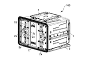
図1は、本発明の基板収納容器をほぼ正面側から観た斜視図である。図2は、図1に示す基板収納容器を底部から観た斜視図である。図1および図2に示す基板収納容器100は、収納する基板としてたとえば半導体ウェーハであり、その直径はたとえば450mmとなっている。
DESCRIPTION OF EMBODIMENTS Hereinafter, embodiments for carrying out the present invention (hereinafter referred to as embodiments) will be described in detail with reference to the accompanying drawings. Note that the same number is assigned to the same element throughout the description of the embodiment.
(Embodiment 1)
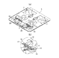
FIG. 1 is a perspective view of the substrate storage container of the present invention viewed from the front side. FIG. 2 is a perspective view of the substrate storage container shown in FIG. 1 viewed from the bottom. A
図1において、基板収納容器100は、容器本体1と蓋体2とからなっている。容器本体1は正面側に開口部(図示せず)を備えたほぼ立方体をなし、蓋体2は前記開口部をシール可能に閉鎖して配置されるようになっている。
In FIG. 1, a
容器本体1の内部は、図示していないが、容器本体1の内壁面に対向して配置された一対の支持部を備えている。一対の支持部は、それぞれ、容器本体1の開口部から観て、左側内壁面および右側内壁面に形成されている。そして、これら支持部に垂直方向に沿って並設された各溝に、半導体ウェーハの周辺の一部を支持させることにより、該半導体ウェーハを水平状態にして容器本体1内に収納できるようになっている。 Although the inside of the container main body 1 is not illustrated, the container main body 1 includes a pair of support portions disposed to face the inner wall surface of the container main body 1. The pair of support portions are respectively formed on the left inner wall surface and the right inner wall surface as viewed from the opening of the container body 1. Then, by supporting a part of the periphery of the semiconductor wafer in the grooves arranged in parallel along the vertical direction with these support portions, the semiconductor wafer can be stored in the container body 1 in a horizontal state. ing.
容器本体1の天面には、ロボテックフランジ4が取り付けられるようになっており、このロボテックフランジ4を介して工場内に設置されたレール(図示せず)に沿って基板収納容器100を搬送できるようになっている。このロボテックフランジ4は、たとえば、取り付け用のベース部と、このベース部から垂直に立ち上がる左右方向の側壁部と、これら左右方向の側壁部と連結される前後方向の側壁部と、これら各側壁部の上面に形成されたほぼ板状のフランジ部とから構成されている。
A robotic flange 4 is attached to the top surface of the container body 1, and the
蓋体2は、容器本体1の開口部(図示せず)を閉鎖するようにして配置され、施錠機構2aを内蔵して構成されている。この施錠機構2aは、回転可能な円形部材2bと、この円形部材2bに形成された円弧溝2cに挿入されるピン(図示せず)を備え蓋体2の上下方向のそれぞれに延在するアーム2dとによって構成され、円形部材2bの回動によって、アーム2dがその長手方向にスライドし、蓋体2の閉鎖の際には、アーム2dの先端が容器本体1の開口部の周辺の一部に設けた係止溝(図示せず)に係止されるようになっている。円形部材2bは、たとえば図示しない鍵を用いて、回転させるようになっている。なお、施錠機構2aは、たとえば2個設けられ、蓋体2を正面側から観た場合に、左右のそれぞれに設けられている。蓋体2は、このような施錠機構2aを内蔵することから、重量が比較的大きく、このため、基板収納容器100の重心の位置が収納されている半導体ウェーハの中心から正面側(蓋体2側)に偏心するようになっている。この偏心は後に詳述するカウンターウェイト20によって回避できるようになっている。
The
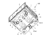
また、容器本体1の底部にはボトムプレート3が取り付けられている。図2に示すように、ボトムプレート3は、容器本体1の底部とほぼ同じ大きさの矩形状をなしている。ボトムプレート3には、たとえば3個の位置決め部材5が内蔵されている。これら位置決め部材5は、容器本体1の開口部(蓋体2側)側の左右に2個設けられ、リア側(蓋体2と反対側)の中央において1個設けられている。すなわち、これら位置決め部材5は、ボトムプレート3上に仮想的に描いた「Y」字の三方向の先端部に位置づけられるように配置されている。これら位置決め部材5は、半導体ウェーハを処理する加工装置の個所に基板収納容器100が搬送されてきた際に、各位置決め部材5に対応する個所に配置された位置決めピンが嵌合されるようになっており、これにより、位置決めの芯出しが行われるようになっている。
A
なお、これら位置決め部材5は、ボトムプレート3の表面に形成された位置決め用貫通穴7から露出されるようになっている。また、ボトムプレート3の面には、容器本体1の開口部から観て、前後方向と左右方向の各周辺にコンベア搬送用のコンベアレール6形成されている。また、容器本体1の開口部(蓋体2側)側に位置する2個の位置決め部材5の間には、基板収納容器100を加工装置に対して固定するため固定手段8が形成されている。
These
さらに、ボトムプレート3には、容器本体1のリア側(蓋体2と反対側)側に位置する位置決め部材5(以下符号5aで示す)の周辺には、識別領域(図中点線枠で囲まれた領域)9が形成されている。識別領域9は、たとえば、容器本体1の開口部側から観た場合、前記位置決め部材5aよりも若干手前の個所に配置されるとともに、該位置決め部材5aを中心にして左右のそれぞれに2個設けられている。
Further, the
これら識別領域9には、それぞれ、ボトムプレート3の表面にたとえば円形からなる複数の第1貫通孔10が形成されている。これら第1貫通孔10は、各識別領域9において、容器本体1の開口部側からリア側への方向に対して直交する方向にたとえば4個並設されて形成されている。これにより、識別領域9には合計8個の第1貫通孔10が形成されることになる。これら第1貫通孔10は、後に詳述する識別部材12が必要に応じて嵌合されるようになっている。また、ボトムプレート3の表面には、第1貫通孔10に近接してスリット状の第2貫通孔11がそれぞれの第1貫通孔10に対応させて形成されている。第2貫通孔11は、容器本体1の開口部側から観た場合、第1貫通孔12よりも手前に位置し、スリットの長手方向は、容器本体1の開口部側からリア側への方向と一致づけられている。この第2貫通孔11は、第1貫通孔10に前記識別部材12を嵌合させた後において、この識別部材を第1貫通孔12から容易に取り出すため孔となっており、後に詳述する冶具が挿入できるようになっている。また、第2貫通孔11は幅の狭いスリット状となっていることから、作業員がこの第2貫通孔11に指を挿入してしまうということを回避できるようになる。
In each of these
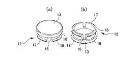
図3(a)、(b)は、識別領域9に形成されている第1貫通穴10に着脱自在に取り付けられる識別部材12を示している。図3(a)は、識別部材12を上方から観た斜視図であり、図3(b)は、識別部材12を下方から観た斜視図である。
FIGS. 3A and 3B show an
図3(a)、(b)に示すように、識別部材12は、円筒部15を有し、この円筒部15の一端は蓋部13によって閉塞されている。蓋部13は、円筒部15の周面よりも径方向に延在されたつば部18を有し、その径は円筒部15の径よりも大きく形成されている。円筒部15の他端は開口され、その開口部には開口周縁から軸方向に延在するたとえば4個の切り欠き16が周方向に等間隔で形成されている。円筒部15の開口周縁は、上述の切り欠き16を設けることにより、弾性変形によって開口周縁の径を変化できるようになっている。また、円筒部15の開口の外周面には径方向に突出する爪部17が設けられている。
As shown in FIGS. 3A and 3B, the
図4は、ボトムプレート3の識別領域9に識別部材12を取り付けた状態を示す断面図である。図4は、第1貫通孔10の中心を通過し第2貫通孔11の延在方向に沿った線における断面図となっている。
FIG. 4 is a cross-sectional view showing a state in which the
図4において、ボトムプレート3があり、その図中上側はボトムプレート3の内部に相当するようになっている。ここで、ボトムプレート3の貫通穴10は、その周縁がボトムプレート3の内部側に突出するとともに、内径を小さくする突起部10Aを有する段つき穴として構成されている。
In FIG. 4, there is a
識別部材12は、ボトムプレート3対して図中下側から第1貫通孔10に挿入されるようになっている。識別部材12は爪部17を先にして第1貫通孔10に挿入されるようになっている。第1貫通孔10に挿入された識別部材12は、爪部17が第1貫通孔10の周縁に形成された突起部10Aを乗り越え、つば部18が、第1貫通孔10の周縁表面に接触するとともに、円筒部15に前記突起部10Aが対向することにより、該第1貫通孔10に係止されるようになっている。このため、第1貫通孔10に挿入された後の識別部材12は第1貫通孔10からは容易に外れ難くなるという効果を奏するようになる。
The
第1貫通孔10に挿入された識別部材12は蓋部13を有することから、これにより、第1貫通孔10は識別部材12によって閉鎖されるようになる。したがって、第1貫通孔10の識別部材12による選択的な閉塞によって、第1貫通孔10の有り無しの状態を基板収納容器100の仕様に対応させることができる。加工装置側では、これらの第1貫通孔10の有り無しの状態をセンシングすることにより、基板収納容器100の各種の仕様を検出することができる。
Since the
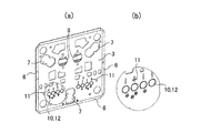
図5(a)は、第1貫通孔10のそれぞれに識別部材12を取り付けた場合のボトムプレート3の平面図を示し、このうち、識別領域9(図5(a)の実線丸枠)を、図5(b)によって拡大して示している。ボトムプレート3の表面と識別部材12の蓋部13の表面とはほぼ面一となっている。また、図6(a)は、図5(a)に示すボトムプレート3を裏返して示した斜視図である。図6(b)は、図6(a)に示す識別領域9(実線丸枠)を拡大して示した図である。図6(b)からも明らかなように、第1貫通孔10に挿入された識別部材12は、その切り欠き部16および爪部17等が目視されるようになっている。
FIG. 5A shows a plan view of the
そして、図6(a)に示すように、並設される第1貫通孔10のうち一番外側の第1貫通孔10の周囲に、作業員の指挿入を防止する邪魔板19が設けられている。邪魔板19は、ボトムプレート3に壁状に植設されて形成されている。
この邪魔板19は、第1貫通孔10に隣接して配置される比較的径の大きな孔に作業員が指を入れ、誤って識別部材12を第1貫通孔10から外してしまうのを防止できるようになっている。また、ボトムプレート3の裏面には、識別領域9の近傍においてたとえば2個のカウンターウェイト20が取り付けられている。
As shown in FIG. 6A, a
This
カウンターウェイト20は、容器本体1の開口部側から観て、それぞれの識別領域9よりも奥側に配置されている。このカウンターウェイト20は容器本体1の蓋体2の重量とバランスをとり、これにより、基板収納容器100の重心位置を基板収納容器100に収納される半導体ウェーハの中心近傍に一致させることができるようになる。
The
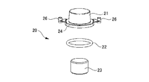
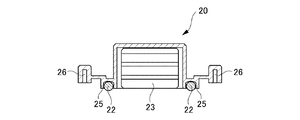
図7、図8は、それぞれ、カウンターウェイト20の展開斜視図と、断面図を示している。カウンターウェイト20は、図7に示すように、ウェイトカバー21と、密封用のOリング22と、ウエイト本体23とを有していて、ボトムプレート3に取り付けられるようになっている。ウェイトカバー21は、上部が閉塞された円筒状をなし、下端の開口部周縁にはフランジ部24を有している。フランジ部24には、ボトムプレート3との間にシールを形成するOリング21を収納可能な溝25(図8参照)が形成されていて、この溝25にOリングが収納されるようになっている。フランジ部24の外側には、ボトムプレートへの取り付け用の円柱ボス26がたとえば2箇所に形成されている。ウエイト本体23は、アルミやSUSなどの金属部材を用いることができ、ウェイトカバー21の形状に対応した円柱形状となっている。ウエイト本体23の表面は、金属イオンによる汚染を防止するため樹脂コーティングを施しておくことが好ましい。
7 and 8 show a developed perspective view and a sectional view of the
図9は、ボトムプレート3の第1貫通孔10に挿入された識別部材12を極めて容易に取り外すための治具27を示した斜視図である。冶具27は、把持部28と、この把持部28からある程度伸長した後にJ字状に屈曲する鍵部29を有して構成されている。
FIG. 9 is a perspective view showing a
図10(a)ないし(c)は、冶具27を用いて、ボトムプレート3の第1貫通孔10に嵌合された識別部材12を取り外す手順を示した説明図である。まず、図10(a)に示すように、冶具27は、その鍵部29をボトムプレート3の第2貫通孔11に挿入して用いられる。鍵部29は平面的に観た場合に線分状となっていることから、スリット状に形成された第2貫通孔11には容易に挿入させることができ。その後、図10(b)に示すように、鍵部29を第1貫通孔10側に移動できるように冶具27を操作すると、鍵部29の先端は、第1貫通孔10に挿入されている識別部材12の上方に位置づけられるようになる。そして、図10(c)に示すように、冶具27を手前に引くように操作することにより、鍵部29の先端は、識別部材12をボトムプレート3から外れる方向に押圧するようになる。鍵部29の先端によって押圧された識別部材12は、切り欠き16が形成された円筒部15が弾性変形することにより、爪部17が第1貫通孔10の突起部10Aから外れ、第1貫通孔10から容易に取り外せるようになる。
FIGS. 10A to 10C are explanatory views showing a procedure for removing the
このように構成された基板収納容器100は、ボトムプレート3に形成されている第1貫通孔10に嵌合されている識別部材12を、冶具27を用いて容易に外すことができるようになる。また、たとえ近傍にカウンターウェイト20が配置されていても、カウンターウェイト20が障害となることなく、第1貫通孔10に嵌合されている識別部材12を、冶具27を用いて容易に外すことができるようになる。
(実施態様2)
The
(Embodiment 2)
実施態様1では、識別部材12をボトムプレート3に形成した第1貫通孔10に対して着脱自在に構成し、識別部材12の有り無しで、それぞれの情報を表すようにしたものである。しかし、識別部材をボトムプレートに形成した長孔に嵌合させるようにし、識別部材を長孔の一端側(第1位置)に移動させ、あるいは他端側(第2位置)に移動させることによって、それぞれの情報を表すように構成してもよい。
In Embodiment 1, the
図11は、識別部材30をボトムプレート3上で移動できるように構成した場合の平面図である。図11は、識別領域をボトムプレート3の表面側から観た図となっている。
FIG. 11 is a plan view when the
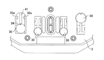
図11において、識別領域にはたとえば4個の識別部材30が取り付けられている。これら識別部材30のうち一つの識別部材(たとえば図中一番左側にある識別部材)について説明すると、該識別部材30はボトムプレート3に形成された長孔41に沿って移動できるようになっている。図11は、該識別部材30が長孔の一端に位置づけられて示され、図11に対応して描いた図12には、該識別部材30が長孔41の他端に位置づけられて示されている。長孔41は識別部材30のガイドレールとしての機能を有するようになっている。
In FIG. 11, for example, four
図13は、識別部材30のみを取り出した示した斜視図である。識別部材30は、平坦な円形部材からなる検出部31と、この検出部31の中心から垂直に延在する支柱部32と、この支柱部32の端部に形成され検出部31と平行に配置される棒状の脚部33とから構成されている。ここで、脚部33の両端はたとえば球状面となっている。また、検出部31の表面の一部には小さな径を有する孔34が設けられている。この孔34は図示せぬ冶具の鍵部が挿入されて識別部材30をボトムプレート3上で移動させる際に用いられるようになっている。
FIG. 13 is a perspective view showing only the
識別部材30の支柱部32は前記長孔41内に位置づけられるようになっており、検出部31と脚部33はボトムプレート3を表裏から挟むように位置づけられるようになっている。
The
長孔41の一端はこの長孔41と交差するようにして識別部材30の挿入孔42が設けられ、識別部材30の脚部33の形状に対応した形状となっている。これにより、識別部材30はその脚部33側から挿入口42に挿入させることによって、支柱部32を前記長孔41内に位置づけさせるようにできるようになっている。
One end of the
識別部材30が、図11に示すように、長孔31の一端に移動した場合、長孔11の両側に表面が球状となっている係止部50(図12にて符号50aで示す)が配置され、識別部材30の脚部33の両端(球状となっている)が該係止部50aを乗り越えて移動することによって、たとえば第1位置における停止を確保できるようになっている。同様に、識別部材30が、図12に示すように、長孔41の他端に移動した場合、長孔41の両側に表面が球状となっている係止部50(図11にて符号50bで示す)が配置され、識別部材30の脚部33の両端(球状となっている)が該係止部50bを乗り越えて移動することによって、たとえば第1位置における停止を確保できるようになっている。この場合、図11に示すように、前記係止部50bに対して挿入孔42側に近接する個所に該係止部50bよりも長孔42側に若干大きく突出する係止部50(図11にて符号50cで示す)が設けられ、識別部材30の脚部33が挿入孔42にまで移動して識別部材30が離脱してしまうのを防止できるようになっている。
When the
長孔41に沿った識別部材30の移動(スライド)は、第1位置と第2位置とのいずれかにおいて停止を充分に確保できるために、比較的大きな力を要するようになっている。しかし、この識別部材30の移動は、たとえば鍵部を有する冶具を用い、該鍵部の先端を検出部31の孔34に係止させた状態で所望の方向に引っ張ることによって容易になされるようになる。
The movement (sliding) of the
このように構成された基板収納容器100は、ボトムプレート3に形成されている長孔41に嵌合されている識別部材30を、冶具を用いて容易にスライドさせることができるようになる。また、たとえ近傍にカウンターウェイト20が配置されていても、カウンターウェイト20が妨害となることなく、長孔41に嵌合されている識別部材30を、冶具を用いて容易にスライドさせることができるようになる。
The
以上、実施形態を用いて本発明を説明したが、本発明の技術的範囲は上記実施形態に記載の範囲には限定されないことは言うまでもない。上記実施形態に、多様な変更または改良を加えることが可能であることが当業者に明らかである。またその様な変更または改良を加えた形態も本発明の技術的範囲に含まれ得ることが、特許請求の範囲の記載から明らかである。 As mentioned above, although this invention was demonstrated using embodiment, it cannot be overemphasized that the technical scope of this invention is not limited to the range as described in the said embodiment. It will be apparent to those skilled in the art that various modifications or improvements can be added to the above-described embodiments. Further, it is apparent from the scope of the claims that the embodiments added with such changes or improvements can be included in the technical scope of the present invention.
1……容器本体、2……蓋体、2a……施錠機構、2b……円形部材、2c……円弧溝、2d……アーム、3……ボトムプレート、4……ロボティックフランジ、5……位置決め部材、6……コンベアレール、7……位置決め用貫通穴、8……固定手段、9……識別領域、10……第1貫通孔、10A……突起部、11……第2貫通穴、12……識別部材、13……蓋部、15……円筒部、16……切り欠き、17……爪部、18……つば部、19……邪魔板、20……カウンターウェイト、21……ウェイトカバー、22……Oリング、23……ウエイト本体、24……フランジ、25……Oリング収納溝、26……円柱ボス、27……治具、8……把持部、29……鍵部、30……識別部材、31……検出部、32……支柱部、33……脚部、34……孔、41……長孔、42……挿入孔、100……基板収納容器。
DESCRIPTION OF SYMBOLS 1 ... Container body, 2 ... Lid body, 2a ... Locking mechanism, 2b ... Circular member, 2c ... Circular groove, 2d ... Arm, 3 ... Bottom plate, 4 ... Robotic flange, 5 ... ... positioning member, 6 ... conveyor rail, 7 ... positioning through hole, 8 ... fixing means, 9 ... identification area, 10 ... first through hole, 10A ... projection, 11 ... second penetration Hole: 12: Identification member, 13: Cover part, 15: Cylindrical part, 16: Notch, 17: Claw part, 18: Brim part, 19: Baffle plate, 20: Counterweight, 21... Weight cover, 22... O-ring, 23... Weight body, 24. Flange, 25. O-ring storage groove, 26. ... Key part, 30 ... Identification member, 31 ... Detection part, 32 ... Stand part, 33 ... Parts, 34 ...... hole, 41 ...... slots, 42 ......
Claims (5)
前記ボトムプレートの識別領域に、貫通孔の開閉を行い、あるいは貫通孔に沿ってスライドする識別部材を備え、
前記識別部材は、冶具を用いて貫通孔から取り外すようにし、あるいはスライドできるようにしたことを特徴とする基板収納容器。 A container storage container comprising: a container main body that has an opening and stores a substrate through the opening; a lid that closes the opening of the container main body; and a bottom plate that is attached to a bottom portion of the container main body.
The identification area of the bottom plate is provided with an identification member that opens and closes a through hole or slides along the through hole,
A substrate storage container characterized in that the identification member can be removed from the through-hole using a jig or slidable.
複数の前記第1貫通孔のそれぞれに近接して配置された第2貫通孔が形成され、
前記第1貫通孔に取り付けられている識別部材は前記第2貫通孔を通した冶具によって取り外せるようになっていることを特徴とする請求項1に記載の基板収納容器。 A plurality of first through holes are formed in the identification region of the bottom plate, and includes an identification member that is detachably attached to a first through hole selected from these first through holes,
A second through hole is formed in proximity to each of the plurality of first through holes;
2. The substrate storage container according to claim 1, wherein the identification member attached to the first through hole can be removed by a jig through the second through hole.
Priority Applications (1)
| Application Number | Priority Date | Filing Date | Title |
|---|---|---|---|
| JP2010264167A JP2012114371A (en) | 2010-11-26 | 2010-11-26 | Substrate storage container |
Applications Claiming Priority (1)
| Application Number | Priority Date | Filing Date | Title |
|---|---|---|---|
| JP2010264167A JP2012114371A (en) | 2010-11-26 | 2010-11-26 | Substrate storage container |
Publications (1)
| Publication Number | Publication Date |
|---|---|
| JP2012114371A true JP2012114371A (en) | 2012-06-14 |
Family
ID=46498232
Family Applications (1)
| Application Number | Title | Priority Date | Filing Date |
|---|---|---|---|
| JP2010264167A Pending JP2012114371A (en) | 2010-11-26 | 2010-11-26 | Substrate storage container |
Country Status (1)
| Country | Link |
|---|---|
| JP (1) | JP2012114371A (en) |
Cited By (2)
| Publication number | Priority date | Publication date | Assignee | Title |
|---|---|---|---|---|
| KR20150001624A (en) * | 2013-06-26 | 2015-01-06 | 가부시키가이샤 다이후쿠 | Inspection apparatus for article storage facility |
| CN105556653A (en) * | 2013-06-18 | 2016-05-04 | 安格斯公司 | Front opening wafer container with weight ballast |
-
2010
- 2010-11-26 JP JP2010264167A patent/JP2012114371A/en active Pending
Cited By (8)
| Publication number | Priority date | Publication date | Assignee | Title |
|---|---|---|---|---|
| CN105556653A (en) * | 2013-06-18 | 2016-05-04 | 安格斯公司 | Front opening wafer container with weight ballast |
| JP2016522586A (en) * | 2013-06-18 | 2016-07-28 | インテグリス・インコーポレーテッド | Front open wafer container with heavy ballast |
| TWI645492B (en) * | 2013-06-18 | 2018-12-21 | 恩特葛瑞斯股份有限公司 | Front opening wafer container with weight ballast |
| US10304710B2 (en) | 2013-06-18 | 2019-05-28 | Entegris, Inc. | Front opening wafer container with weight ballast |
| KR20150001624A (en) * | 2013-06-26 | 2015-01-06 | 가부시키가이샤 다이후쿠 | Inspection apparatus for article storage facility |
| JP2015012040A (en) * | 2013-06-26 | 2015-01-19 | 株式会社ダイフク | Inspection device for article storage facility |
| US9541534B2 (en) | 2013-06-26 | 2017-01-10 | Daifuku Co., Ltd. | Inspection apparatus for article storage facility |
| KR102230532B1 (en) * | 2013-06-26 | 2021-03-19 | 가부시키가이샤 다이후쿠 | Inspection apparatus for article storage facility |
Similar Documents
| Publication | Publication Date | Title |
|---|---|---|
| JP5269077B2 (en) | Support and substrate storage container | |
| JP2007019218A5 (en) | ||
| JP2013239643A (en) | Substrate housing container | |
| KR20130142915A (en) | Robot hand | |
| US11052830B2 (en) | Display holder | |
| JP2018077966A (en) | Cartridge holding device | |
| JP6185268B2 (en) | Substrate storage container | |
| JP2011181867A (en) | Substrate storage container | |
| JP2009147171A5 (en) | ||
| JP2012114371A (en) | Substrate storage container | |
| JP2016096260A (en) | Tray feeder and component mounting device | |
| JP2010192801A (en) | Substrate storing container | |
| JP5916508B2 (en) | Substrate storage container | |
| JP2014007191A (en) | Nozzle stocker | |
| JP2012064828A (en) | Cassette adaptor and seating sensor mechanism | |
| JP6083748B2 (en) | Substrate storage container | |
| JP2009170726A (en) | Load port and method for adjusting cassette position | |
| KR101963400B1 (en) | Substrate processing apparatus | |
| JP2016025201A (en) | Nozzle exchanger | |
| JP2016219537A (en) | Purge device and purge stocker | |
| WO2018034101A1 (en) | Substrate-accommodating container | |
| JP2005197431A (en) | Load port device | |
| JP2022016234A (en) | Carrier device and carrier kit | |
| JP3944485B2 (en) | Substrate chucking device | |
| JP4218003B2 (en) | Structure for retaining board storage box in gaming machine |