JP2012106918A - Method for producing luminous body, luminous body produced by the same, and stone for nail using luminous body - Google Patents
Method for producing luminous body, luminous body produced by the same, and stone for nail using luminous body Download PDFInfo
- Publication number
- JP2012106918A JP2012106918A JP2011231846A JP2011231846A JP2012106918A JP 2012106918 A JP2012106918 A JP 2012106918A JP 2011231846 A JP2011231846 A JP 2011231846A JP 2011231846 A JP2011231846 A JP 2011231846A JP 2012106918 A JP2012106918 A JP 2012106918A
- Authority
- JP
- Japan
- Prior art keywords
- layer
- phosphorescent
- laminate
- luminous body
- manufacturing
- Prior art date
- Legal status (The legal status is an assumption and is not a legal conclusion. Google has not performed a legal analysis and makes no representation as to the accuracy of the status listed.)
- Granted
Links
Images


Classifications
-
- C—CHEMISTRY; METALLURGY
- C03—GLASS; MINERAL OR SLAG WOOL
- C03B—MANUFACTURE, SHAPING, OR SUPPLEMENTARY PROCESSES
- C03B19/00—Other methods of shaping glass
- C03B19/10—Forming beads
-
- C—CHEMISTRY; METALLURGY
- C03—GLASS; MINERAL OR SLAG WOOL
- C03B—MANUFACTURE, SHAPING, OR SUPPLEMENTARY PROCESSES
- C03B19/00—Other methods of shaping glass
- C03B19/06—Other methods of shaping glass by sintering, e.g. by cold isostatic pressing of powders and subsequent sintering, by hot pressing of powders, by sintering slurries or dispersions not undergoing a liquid phase reaction
-
- A—HUMAN NECESSITIES
- A44—HABERDASHERY; JEWELLERY
- A44C—PERSONAL ADORNMENTS, e.g. JEWELLERY; COINS
- A44C17/00—Gems or the like
-
- A—HUMAN NECESSITIES
- A45—HAND OR TRAVELLING ARTICLES
- A45D—HAIRDRESSING OR SHAVING EQUIPMENT; EQUIPMENT FOR COSMETICS OR COSMETIC TREATMENTS, e.g. FOR MANICURING OR PEDICURING
- A45D29/00—Manicuring or pedicuring implements
-
- C—CHEMISTRY; METALLURGY
- C03—GLASS; MINERAL OR SLAG WOOL
- C03B—MANUFACTURE, SHAPING, OR SUPPLEMENTARY PROCESSES
- C03B19/00—Other methods of shaping glass
- C03B19/10—Forming beads
- C03B19/1005—Forming solid beads
-
- A—HUMAN NECESSITIES
- A45—HAND OR TRAVELLING ARTICLES
- A45D—HAIRDRESSING OR SHAVING EQUIPMENT; EQUIPMENT FOR COSMETICS OR COSMETIC TREATMENTS, e.g. FOR MANICURING OR PEDICURING
- A45D29/00—Manicuring or pedicuring implements
- A45D2029/005—Printing or stamping devices for applying images or ornaments to nails
-
- Y—GENERAL TAGGING OF NEW TECHNOLOGICAL DEVELOPMENTS; GENERAL TAGGING OF CROSS-SECTIONAL TECHNOLOGIES SPANNING OVER SEVERAL SECTIONS OF THE IPC; TECHNICAL SUBJECTS COVERED BY FORMER USPC CROSS-REFERENCE ART COLLECTIONS [XRACs] AND DIGESTS
- Y10—TECHNICAL SUBJECTS COVERED BY FORMER USPC
- Y10T—TECHNICAL SUBJECTS COVERED BY FORMER US CLASSIFICATION
- Y10T428/00—Stock material or miscellaneous articles
- Y10T428/25—Web or sheet containing structurally defined element or component and including a second component containing structurally defined particles
-
- Y—GENERAL TAGGING OF NEW TECHNOLOGICAL DEVELOPMENTS; GENERAL TAGGING OF CROSS-SECTIONAL TECHNOLOGIES SPANNING OVER SEVERAL SECTIONS OF THE IPC; TECHNICAL SUBJECTS COVERED BY FORMER USPC CROSS-REFERENCE ART COLLECTIONS [XRACs] AND DIGESTS
- Y10—TECHNICAL SUBJECTS COVERED BY FORMER USPC
- Y10T—TECHNICAL SUBJECTS COVERED BY FORMER US CLASSIFICATION
- Y10T428/00—Stock material or miscellaneous articles
- Y10T428/29—Coated or structually defined flake, particle, cell, strand, strand portion, rod, filament, macroscopic fiber or mass thereof
- Y10T428/2982—Particulate matter [e.g., sphere, flake, etc.]
- Y10T428/2991—Coated
- Y10T428/2993—Silicic or refractory material containing [e.g., tungsten oxide, glass, cement, etc.]
- Y10T428/2996—Glass particles or spheres
Landscapes
- Chemical & Material Sciences (AREA)
- Engineering & Computer Science (AREA)
- Manufacturing & Machinery (AREA)
- Materials Engineering (AREA)
- Organic Chemistry (AREA)
- Dispersion Chemistry (AREA)
- Laminated Bodies (AREA)
- Adornments (AREA)
- Illuminated Signs And Luminous Advertising (AREA)
Abstract
【課題】 簡便な設備で効率よく粒状の蓄光体を製造することが可能な蓄光体の製造方法及びこれにより製造された蓄光体並びに蓄光体を用いたネイル用ストーンを提供すること。
【解決手段】 蓄光材料とガラス材料を少なくとも含有する蓄光体の製造方法において、少なくとも蓄光材料及びガラス材料を混合してペースト状の混合物2を作る。この混合物2を複数の層に積層させて粒状の積層体3を形成する。この積層体3を溶融するように焼成して溶融状態の表面張力により成形させる。
【選択図】 図3PROBLEM TO BE SOLVED: To provide a method for producing a phosphorescent body capable of efficiently producing a granular phosphorescent body with simple equipment, a phosphorescent body produced thereby, and a nail stone using the phosphorescent body.
In a method for producing a phosphor containing at least a phosphorescent material and a glass material, at least the phosphorescent material and the glass material are mixed to form a paste-like mixture. The mixture 2 is laminated on a plurality of layers to form a granular laminate 3. The laminate 3 is fired so as to be melted and formed by surface tension in a molten state.
[Selection] Figure 3
Description
本発明は、蓄光体の製造方法及びこれにより製造された蓄光体並びに蓄光体を用いたネイル用ストーンに関する。さらに詳しくは、蓄光材料とガラス材料を少なくとも含有する蓄光体の製造方法及びこれにより製造された蓄光体並びに蓄光体を用いたネイル用ストーンに関する。 The present invention relates to a method for producing a phosphorescent body, a phosphorescent body produced thereby, and a nail stone using the phosphorescent body. More specifically, the present invention relates to a method for producing a phosphor containing at least a phosphorescent material and a glass material, a phosphor for producing the phosphor, and a nail stone using the phosphor.
従来、上述の如き蓄光体の製造方法として、例えば特許文献1〜3に記載の如きものが知られている。特許文献1では、ガラス管の中空部に蓄光粉末を充填し延伸させて繊維状ガラスを生成し、その繊維状ガラスを傾斜状に配置した加熱炉に投入して融点以上で熔解させて表面張力によりガラス小球を製造している。また、特許文献2では、蓄光カレットを流動焼成法によって焼成してガラスビーズを製造している。いずれの製造方法においても、使用する装置が複雑且つ大掛かりで、製造工程も煩雑となっていた。
Conventionally, for example, the methods described in
また、特許文献3では、蓄光材とガラス材よりなる混合材を焼成し板状ガラスを生成し、その板状ガラスを所定の粒径に粉砕して再度焼成することにより発光部を含む粒状部を形成している。そのため、発光部を含む粒状部の生産効率は低く、製造工程も未だ煩雑であった。また、粒状部の形状にバラツキも生じる場合があった。
Moreover, in
かかる従来の実情に鑑みて、本発明は、簡便な設備で効率よく粒状の蓄光体を製造することが可能な蓄光体の製造方法及びこれにより製造された蓄光体並びに蓄光体を用いたネイル用ストーンを提供することを目的とする。 In view of such a conventional situation, the present invention is a method for manufacturing a phosphorescent body capable of efficiently producing a granular phosphorescent body with simple equipment, a phosphorescent body manufactured thereby, and a nail using the phosphorescent body. The purpose is to provide stones.
上記目的を達成するため、本発明に係る蓄光体の製造方法の特徴は、蓄光材料とガラス材料を少なくとも含有する蓄光体の製造方法において、少なくとも前記蓄光材料及び前記ガラス材料を混合してペースト状の混合物を作り、この混合物を複数の層に積層させて粒状の積層体を形成し、この積層体を溶融するように焼成して溶融状態の表面張力により成形させることにある。 In order to achieve the above object, a method of manufacturing a phosphorescent material according to the present invention is characterized in that, in the phosphorescent material manufacturing method containing at least a phosphorescent material and a glass material, at least the phosphorescent material and the glass material are mixed and pasted. The mixture is laminated in a plurality of layers to form a granular laminate, and the laminate is baked to be melted and molded by surface tension in a molten state.
上記構成によれば、積層体はペースト状の混合物を積層させた構造であるので、焼成前の積層体は流動性が低い。積層体を溶融するように焼成することで、積層体は流動性が高まり液状となり、積層体には表面張力が発生する。表面張力は、表面が自ら収縮してできるだけ小さな面積となるように表面に沿って作用する張力であり、積層体の形状に応じて張力が発生する。また、表面張力は液体の種類によっても異なる。従って、溶融状態の表面張力によって形状が変化することとなり、所望の形状に成形させることができる。 According to the above configuration, since the laminate has a structure in which paste-like mixtures are laminated, the laminate before firing has low fluidity. By baking the laminated body so as to melt, the laminated body becomes more fluid and becomes liquid, and surface tension is generated in the laminated body. The surface tension is a tension that acts along the surface so that the surface contracts by itself to have as small an area as possible, and the tension is generated according to the shape of the laminate. Further, the surface tension varies depending on the type of liquid. Therefore, the shape changes depending on the surface tension in the molten state, and can be formed into a desired shape.
また、形成された積層体は、その積層体との接着性を有する樹脂製の支持層によって炉に移動され、焼成されるようにするとよい。樹脂製の支持層は焼成により焼失するので、より効率よく蓄光体を製造することができる。 The formed laminate is preferably moved to a furnace and fired by a resin support layer having adhesiveness to the laminate. Since the resin-made support layer is burned off by firing, the phosphor can be manufactured more efficiently.
係る場合、前記積層体は前記支持層の表面に順次積層されて形成され、積層体を支持層の上に配向した状態で前記焼成を行うとよい。積層体を樹脂の上に形成でき、印刷等による形成が容易である。しかも、積層体が支持層の上に位置する状態で焼成するので、焼成後の蓄光体の表面に与える悪影響を抑制し、仕上がり精度を向上させることができる。 In this case, the laminate is preferably formed by sequentially laminating on the surface of the support layer, and the firing is performed with the laminate oriented on the support layer. A laminated body can be formed on a resin and can be easily formed by printing or the like. Moreover, since the laminate is fired in a state where it is located on the support layer, it is possible to suppress the adverse effect on the surface of the phosphor after firing, and to improve the finishing accuracy.
さらに、前記支持層は転写紙の転写層であり、この転写紙は、台紙の上に水溶性材料よりなる接着層を介して前記転写層が設けられ、前記転写紙を水に漬けることで前記接着層を溶解させ、前記積層体を保持した状態で転写層を前記台紙から分離させ、炉に移動させることが望ましい。これにより、台紙を有する転写紙の上に積層体を形成するので、より寸法精度が向上する。しかも、転写層を薄く形成でき、水に漬けることで台紙からの分離も容易であり、作業効率もさらに向上する。 Further, the support layer is a transfer layer of a transfer paper, and the transfer paper is provided on the mount via an adhesive layer made of a water-soluble material, and the transfer paper is immersed in water by being immersed in water. It is desirable to dissolve the adhesive layer and separate the transfer layer from the mount while holding the laminate, and move it to a furnace. Thereby, since a laminated body is formed on the transfer paper which has a mount, dimensional accuracy improves more. In addition, the transfer layer can be formed thin, so that it can be easily separated from the mount by soaking in water, and the working efficiency is further improved.
そして、積層させたものを焼成すれば良いため、製造設備は簡便である。また、積層体は多数のものを同時に作成すればよいため、製造効率が良く、しかも精度も安定している。 And since what was laminated | stacked should just be baked, a manufacturing facility is simple. In addition, since a large number of laminates may be formed at the same time, the manufacturing efficiency is good and the accuracy is stable.
係る場合、望ましくは、前記蓄光材料と前記ガラス材料との総量に対して前記蓄光材料が1重量%以上40重量%以下となるように配合して作成されるとよい。この数値範囲内であれば、蓄光材料による発光性能を維持でき、表面張力により精度も安定して成形することが可能である。 In such a case, it is desirable that the phosphorescent material is desirably blended so as to be 1 wt% or more and 40 wt% or less with respect to the total amount of the phosphorescent material and the glass material. If it is in this numerical range, the light emission performance by the phosphorescent material can be maintained, and the molding can be performed with a stable accuracy by the surface tension.
前記積層体は、前記蓄光材料の配合量が異なる複数種の混合物から形成されても構わない。また、前記積層体は、前記層の面積が異なる複数種の層から構成されても構わない。積層体の層において蓄光顔料の量とガラス材料の量を異ならせることで、表面張力に差が生じ、所望の形状に精度も安定して成形することができる。 The said laminated body may be formed from the multiple types of mixture from which the compounding quantity of the said luminous material differs. Moreover, the said laminated body may be comprised from the multiple types of layer from which the area of the said layer differs. By differentiating the amount of the phosphorescent pigment and the amount of the glass material in the layer of the laminate, a difference in surface tension occurs, and the desired shape can be stably molded with high accuracy.
前記積層体の最下層の下及び/又は最上層の上には、前記ガラス材料よりなるコート層を設けるとよい。蓄光材料の含有量が多くなると、生成される蓄光体の表面に存在する蓄光顔料により表面に凹凸が生じ平滑性が低下する。最下層及び/又は最上層をガラス材料よりなるコート層とすることで、平滑性を向上させることができる。また、ガラス材料で構成することで発光性能も維持することができる。 A coat layer made of the glass material may be provided below and / or above the uppermost layer of the laminate. When the content of the phosphorescent material is increased, the phosphorescent pigment present on the surface of the phosphorescent material to be produced causes irregularities on the surface and the smoothness decreases. By making the lowermost layer and / or the uppermost layer a coating layer made of a glass material, smoothness can be improved. Moreover, the light emission performance can be maintained by using a glass material.
前記コート層の厚さを他の層と異ならせるとよい。これにより、精密な形状を得られ且つ肉厚の積層体を形成することができる。従って、効率よく発光性能のよい蓄光体を生成することができる。 The thickness of the coat layer may be different from that of other layers. Thereby, a precise shape can be obtained and a thick laminate can be formed. Therefore, it is possible to efficiently generate a phosphor with good light emission performance.
そして、前記積層体は、スクリーン印刷を複数回行うことで形成するとよい。製造設備は簡便で、多数のものを同時に作成でき、製造効率が良い。 And the said laminated body is good to form by performing screen printing in multiple times. Manufacturing equipment is simple, many can be created simultaneously, and manufacturing efficiency is good.
また、前記混合物はメジウムを含み、前記層を形成する毎に乾燥させるとよい。メジウムに含まれる有機溶剤が焼成時に残存しているとススとなり黒ずんでしまう。層を形成する毎に乾燥させることで、その有機溶剤を気化させて発光性能の低下を防止する。上記いずれかに記載の蓄光体の製造方法により製造された蓄光体は、例えば、ネイル用ストーンとして使用することができる。 The mixture contains medium and is preferably dried each time the layer is formed. If the organic solvent contained in the medium remains at the time of firing, it becomes sooted and darkened. By drying each time a layer is formed, the organic solvent is vaporized to prevent a decrease in light emitting performance. The phosphorescent body manufactured by any one of the above phosphorescent body manufacturing methods can be used as, for example, a nail stone.
上記本発明に係る粒状蓄光体の製造方法及びこれにより製造された蓄光体並びに蓄光体を用いたネイル用ストーンの特徴によれば、簡便な設備で効率よく粒状の蓄光体を製造することが可能となった。 According to the method for producing a granular phosphor according to the present invention and the characteristics of the phosphor for producing the phosphor and the stone for nail using the phosphor, it is possible to efficiently produce a granular phosphor with simple equipment. It became.
本発明の他の目的、構成及び効果については、以下の発明の実施の形態の項から明らかになるであろう。 Other objects, configurations, and effects of the present invention will become apparent from the following embodiments of the present invention.
次に、図1〜5を参照しながら、本発明の第一実施形態について説明する。
本発明に係る蓄光体1は、蓄光材料としての蓄光顔料と、ガラス材料としてのガラスフリットを少なくとも含有する粒状の焼結体である。この蓄光体1は、蓄光顔料及びガラスフリットを混合して作成したペースト状の混合物2を複数の層に積層させて粒状の積層体3を形成し、この積層体3を溶融するように焼成して溶融状態の表面張力により成形させたものである。
Next, a first embodiment of the present invention will be described with reference to FIGS.
The
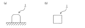
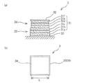
図1に示すように、第一実施形態に係る蓄光体1は、略立方体形状を呈する。この蓄光体1は、図2に示す如き粒状の積層体3を焼成することで得られる。この積層体3は、図2(a)に示すように、混合物2よりなる6層構造の蓄光層31と、コート層30,32とからなる。また、同図(b)に示すように、積層体3は平面視で略方形を呈する。
As shown in FIG. 1, the
蓄光層31は、第1層31a乃至第3層31cからなる下層部分33と、第4層31d乃至第6層31fからなる上層部分34とから構成されている。図2(b)に示すように、本実施形態において、積層方向に直交する面の面積は、上層部分34の各層31d〜31fより下層部分33の各層31a〜31cが大きい。蓄光層31の上側と下側とで各層の面積を異ならせると、蓄光体1表面の仕上がりが滑らかなものとなる。なお、本実施形態では、例えば上層部分34の辺の長さLを下層部分33の1辺より10%程度小さく設定する。
The
べースコート層30は最下層としての第1層31aの下層の下に設けられ、オーバーコート層32は、蓄光層31の最上層としての第6層31fの上に設けられる。これらのコート層30,32は、蓄光顔料を含まないガラスフリットよりなる。ベースコート層30は後述するように角をシャープに仕上げるのに有用である。一方、蓄光層31に含まれる蓄光顔料は粒径が大きいため、蓄光体1の表面に蓄光顔料によって凹凸が形成される場合がある。蓄光顔料を含まないオーバーコート層32を設けることで、積層体3の焼成によってオーバーコート層32が溶融し、表面の凹凸を防止し平滑にすると共に積層体3の角(端部)を滑らかに仕上げることができる。しかも、上下対称にコート層30,32を設けることで、積層体3の溶融時の表面張力のバランスが保たれるので、不均一な表面張力の発生を防止し、形状のバラツキを防止することができる。
The
蓄光層31を構成する各層は、コート層30,32よりも厚い。蓄光層31を厚くすることで、単位面積当たりの蓄光顔料の含有量を効率よく増加させることができる。また、コート層30,32は蓄光顔料を含んでいないので、蓄光層31よりも表面張力が大きく作用する。これにより、成形される蓄光体を滑らかに仕上げることができ、且つ発光性能を効率よく向上させることが可能となる。
Each layer constituting the
蓄光顔料としては、例えばアルカリ土類金属のアルミン酸塩化合物を主成分に希土類元素の賦活剤、共賦活剤を添加焼成して得られたものを用いる。アルカリ土類金属としては、カルシウム、ストロンチウム、バリウム等の少なくとも1以上の金属元素やこれらの金属元素とマグネシウムの合金が挙げられる。希土類元素の賦活剤としては、ユウロピウム、ジスプロシウム等が挙げられる。共賦活剤としては、ランタン、セリウム、プラセオジウム、ネオジウム、サマリウム、カドニウム、テルビウム、ジスプロニウム等の元素が挙げられる。また、蓄光顔料には、上述の如き酸化物蛍光体の他、CaS:Bi(紫青色発光),CaSrS:Bi(青色発光),ZnS:Cu(緑色発光),ZnCdS:Cu(黄色〜橙色発光)等の硫化物蛍光体を用いることも可能である。なお、上述の化合物を適宜混合して用いてもよく、さらに他の無機蛍光顔料や有機蛍光顔料において蓄光性を有するものも用いることが可能である。 As the phosphorescent pigment, for example, a pigment obtained by adding and firing a rare earth element activator or a coactivator containing an alkaline earth metal aluminate compound as a main component is used. Examples of the alkaline earth metal include at least one metal element such as calcium, strontium, and barium, and alloys of these metal elements and magnesium. Examples of the rare earth element activator include europium and dysprosium. Examples of the co-activator include elements such as lanthanum, cerium, praseodymium, neodymium, samarium, cadmium, terbium, and dyspronium. In addition to the oxide phosphors described above, phosphorescent pigments include CaS: Bi (purple blue light emission), CaSrS: Bi (blue light emission), ZnS: Cu (green light emission), ZnCdS: Cu (yellow to orange light emission). It is also possible to use sulfide phosphors such as In addition, you may use the above-mentioned compound by mixing suitably, Furthermore, what has a luminous property in another inorganic fluorescent pigment or an organic fluorescent pigment can also be used.
また、ガラスフリットの材料には、例えば酸化ケイ素、酸化アルミニウム、酸化ホウ素及びアルカリ酸化物を主成分とし且つ酸化カルシウム、酸化ストロンチウム及び酸化マグネシウムからなる群より選択された少なくとも1種のアルカリ土類金属酸化物を含むものが用いられる。なお、ガラスフリットの材料は、先の材料に限定されるものではないが、上述の蓄光顔料が固体で存在可能な温度で溶融(液化)するものを用いるとよい。また、焼成後において、透明度の高いガラスフリットの材料を用いることが望ましい。蓄光顔料の発光が阻害されることがなく、発光性能の低下を防止する。 The material of the glass frit is, for example, at least one alkaline earth metal selected from the group consisting of silicon oxide, aluminum oxide, boron oxide and alkali oxide, and selected from the group consisting of calcium oxide, strontium oxide and magnesium oxide. Those containing oxides are used. The material of the glass frit is not limited to the above material, but a material that melts (liquefies) the above phosphorescent pigment at a temperature at which it can exist as a solid may be used. Further, it is desirable to use a glass frit material with high transparency after firing. The light emission of the phosphorescent pigment is not hindered and the light emission performance is prevented from being lowered.
ここで、本実施形態に係る蓄光体1の製造工程について説明する。この製造工程は、大略、ペースト状の混合物2を作成する混合物作成工程と、作成したペースト状の混合物2を複数の層に積層させて積層体3を形成する積層体形成工程と、積層体3を焼成し溶融時の表面張力により所望の形状に成形する焼成工程とからなる。
Here, the manufacturing process of the
混合物作成工程では、蓄光顔料及びガラスフリットの各粉末と液状のメジウムとを混合してペースト状の混合物2を作成する。ここで、蓄光顔料とガラスフリットとの総量に対して、蓄光顔料が1重量%〜40重量%の範囲内となるように調合する。この数値範囲内であれば、蓄光顔料による発光性能が低下することなく、焼成工程における積層体3の溶融時の表面張力により所望の形状に成形することができる。そして、調合した固形成分(粉状の蓄光顔料及びガラスフリット)の総量に対して、液状のメジウムを適量混合してペースト状の混合物2を作成する。
In the mixture preparation step, each powder of phosphorescent pigment and glass frit and liquid medium are mixed to prepare a paste-
本実施形態では、例えば蓄光顔料とガラスフリットとの総量に対して、蓄光顔料が30重量%となるように調合する。そして、調合した固形成分の総量に対して、液状のメジウムを40重量%で混合する。すなわち、蓄光顔料:ガラスフリット:メジウム=3:7:4の割合にて調合してペースト状の混合物2とする。
In the present embodiment, for example, the phosphorescent pigment is blended so as to be 30% by weight with respect to the total amount of the phosphorescent pigment and the glass frit. And liquid medium is mixed with 40 weight% with respect to the total amount of the prepared solid component. That is, the mixture is prepared in the ratio of phosphorescent pigment: glass frit: medium = 3: 7: 4 to obtain a paste-
ここで、メジウム4には、例えば、アクリル系、アルキッド系、エポキシ系、ウレタン系、アクリルシリコン系、フッ素系、メラミン系等の1液又は2液タイプのものを用いることができる。このメジウムは、粒状の蓄光体1に成形するために、粉状の蓄光顔料とガラスフリットとのつなぎとなるものであれば、上記材料に限定されるものではない。例えば、スキージオイルや各種のバインダー等を用いることも可能である。なお、調合時において、蓄光顔料、ガラスフリット及びメジウムの他、染料等の添加物を発光性能に影響を与えない範囲内で添加しても構わない。
Here, as the medium 4, for example, one-component or two-component types such as acrylic, alkyd, epoxy, urethane, acrylic silicon, fluorine, and melamine can be used. The medium is not limited to the above materials as long as it forms a connection between the powdery phosphorescent pigment and the glass frit in order to form the
次に、積層体形成工程について説明する。
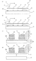
本実施形態では、上述の混合物2を印刷機10により支持部材としての転写紙20上にスクリーン印刷して、上述の積層体3を同時に複数形成する。スクリーン印刷を適用することで、効率よく多量の積層体3を形成することができる。ここで、転写紙20は、図3(c)に示すように、台紙21と樹脂フィルムよりなる支持層としての転写層22と、これらを接着する水溶性の接着層23よりなるものであり、例えば、一般的に陶磁器の絵付けに用いられるものを利用することができる。転写層22は、積層体3との接着性を有し且つ積層体3を焼成する際に焼失する材料であればよい。この転写層22には、例えば、アクリル酸エステル共重合体、ビニル系樹脂、セルローズ系樹脂、その他の炭化水素等の樹脂材料が用いられる。また、接着層23は、例えばデンプン、デキストリン、ポリビニルアルコール、ポリビニルピロリドン、アラビアガム、水溶性アクリル樹脂等の転写紙用糊からなる。
Next, a laminated body formation process is demonstrated.
In the present embodiment, the above-described
まず、図3(a)に示すように、開口13を形成したスクリーン版12’を印刷機10に取り付ける。台11に転写紙20を載置し、取り付けたスクリーン版12’に対して転写紙20の位置合わせを行う。ここで、転写紙20は、スクリーン印刷の際に位置ズレが生じないように、テープ等の固定部材で台11に固定される。本実施形態において、このスクリーン版12’に150メッシュのものを用い、ベースコート層30を形成する。目の細かいスクリーン版12’により顔料を用いないベースコート層30を印刷すれば、角の部等をシャープに形成することが可能となる。
First, as shown in FIG. 3A, the
そして、スクリーン版12’にメジウムとガラスフリットとを混合したペースト状のガラス材2’を配置し、スクリーン版12’上面でスキージを移動させる。これにより、ガラス材2’は開口13を介して下面側へ押し出されるようにして塗布され、転写紙20の転写層22上に塗布(印刷)され、コート層30が形成される。
Then, a paste-
次に、スクリーン版12’をメッシュの異なるスクリーン版12と取り替える。蓄光顔料の粒が大きいため、混合物2に含有する蓄光顔料が開口13を通過できるスクリーン版12を選択する。また、上述のスクリーン版より開口の大きいスクリーン版を用いることで、蓄光層31を肉厚とすることができる。これにより、単位面積当たりの蓄光顔料の含有量は増加し、蓄光体1の発光性能を向上させることができる。本実施形態では、60メッシュのスクリーン版12に交換する。
Next, the screen plate 12 'is replaced with a
そして、図3(b)に示すように、スクリーン版12にペースト状の混合物2を配置し、スクリーン版12上面でスキージ14を移動させる。これにより、混合物2が開口13を通過して塗布(印刷)され、ベースコート層30の上面に蓄光層31の第一層31aが形成される。
Then, as shown in FIG. 3B, the paste-
これを複数回繰り返し行うことで、図3(c)に示すように、層が印刷回数分積層され、積層体3が転写層22の表面22aに順次積層されて形成される。本実施形態では、スクリーン印刷を6回行うことで、第1層31a乃至第6層31fの6層構造の蓄光層31を形成する。そして、再度スクリーン版12を150メッシュのスクリーン版12’に交換し、蓄光層31の第6層31fの上にオーバーコート層32を形成する。
By repeating this a plurality of times, as shown in FIG. 3C, the layers are stacked by the number of times of printing, and the
なお、開口13の形状は、三角形、四角形等の多角形状、円形、楕円形等、適宜設定することが可能である。また、開口13は、本実施形態の如く同一形状のものを複数設けてもよく、異なる形状や大きさのものを複数設けても構わない。本実施形態では、開口13は略方形を呈し、適宜間隔をおいて複数形成されている。
The shape of the
ところで、混合物2及びガラス材2’に用いたメジウムには、炭素を含む有機溶剤が含まれている場合がある。係る場合、後の焼成時にメジウムが残存していると、有機溶剤の炭素がススとなって黒ずんでしまい、蓄光体1の輝度が低下してしまう。そのため、層を一層形成する毎にメジウムを乾燥させる乾燥工程を設ける。これにより、層に存在する有機溶剤を完全に気化させて消滅させて、蓄光体1の輝度の低下を防止する。なお、本実施形態では、上述のスクリーン印刷を行う度に層を乾燥させ、有機溶剤を気化蒸発させる。乾燥工程は、例えば所定時間温風に晒すことにより行う。
By the way, the medium used for the
複数回のスクリーン印刷により積層体3を形成した後、図3(d)に示すように、転写紙20を水に浸漬させる。これにより、水溶性の接着層23が溶解し、積層体3が転写層22に保持されたままで台紙21から転写層22が剥離し分離する。
After the
次に、焼成工程について説明する。
本実施形態においては、図4に示すように、先の転写層22によって複数の積層体3を焼成用下敷51に載置させ炉50に移動させる。下敷51の上で積層体3を転写層22の上に位置(配向)させた状態で炉50に設置し所定の温度(例えば800℃)にて焼成することで、積層体3の表面張力を利用して成形する。また、焼成により転写層22は焼失する。なお、焼成用下敷51には、例えばアルミナシートが用いられるが、積層体3が焼結しない材料や構造のものであれば、特に限定されるものではない。
Next, the firing process will be described.
In the present embodiment, as shown in FIG. 4, the plurality of
ここで、表面張力とは、液体の表面が自ら収縮してできるだけ小さな面積となるように表面に沿って作用する張力である。積層体3を溶融するように焼成すると、積層体3に含まれるガラスフリットが熔解して液状のガラス成分となり、積層体3に表面張力が発生する。一方、蓄光顔料はガラスフリットよりも融点が高く、ガラスフリットの溶融温度では固体で存在する。よって、積層体3に生じる表面張力STは、蓄光顔料の含有量(配合量)によって異なる。
Here, the surface tension is a tension acting along the surface so that the surface of the liquid contracts itself to have as small an area as possible. When the
本実施形態では、調合した固形成分(粉状の蓄光顔料及びガラスフリット)の総量に対して、蓄光顔料は30重量%含まれている。積層体3を所定の温度(例えば800℃)で焼成すると、図5に示すように、略方形の積層体3はその表面張力STによって各辺及び角部に丸みが生じる。この表面張力STにより略立方体形状の蓄光体1が得られる。
In the present embodiment, the phosphorescent pigment is contained in an amount of 30% by weight based on the total amount of the prepared solid components (powdered phosphorescent pigment and glass frit). When the
次に、本発明の第二実施形態について説明する。なお、以下の実施形態において、上記実施形態と同様の部材等には同一の符号を付してある。
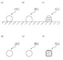
上記第一実施形態において、蓄光顔料とガラスフリットとの総量に対して、蓄光顔料が30重量%となるように調合し、略方形の積層体3を焼成して、蓄光体1を得た。しかし、第二実施形態では、蓄光顔料とガラスフリットとの総量に対して、蓄光顔料を5重量%以上20%重量以下となるように調合する。この数値範囲内であれば、第一実施形態と比べ、焼成時における積層体3の蓄光顔料の含有量は少ない。そのため、焼成時に生じる表面張力STは大きくなる。よって、図6(a)(d)に示す如き、球状の蓄光体1Aを製造することが可能となる。例えば、蓄光顔料とガラスフリットとの総量に対して、蓄光顔料が10重量%となるように調合する。
Next, a second embodiment of the present invention will be described. In the following embodiments, the same members and the like as those in the above embodiments are denoted by the same reference numerals.
In said 1st embodiment, it mixed so that a phosphorescence pigment might be 30 weight% with respect to the total amount of a phosphorescence pigment and glass frit, the substantially square
係る場合、積層体形成工程において、スクリーン版12の開口13を略円形に形成するとよい。また、上記第一実施形態では、積層体3の蓄光層31の上下に対をなすコート層30,32を設けた。しかし、第二実施形態では、コート層32を形成していない。コート層30は、形状に合わせて適宜設ければよい。また、コート層30、32は、上下の層の一方にのみ設けることも可能である。
In such a case, the
最後に他の実施形態の可能性について言及する。
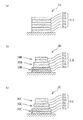
蓄光体1の形状は、第一実施形態の略立方体形状や、第二実施形態の球状に限られるものではない。例えば、図6(b)(e)に示す如き半球状や同図(c)(f)に示す如き階段状の略円錐形状に成形することも可能である。上記第一、第二実施形態においては、図2,図7(a)に示すように、積層体3,3Aの蓄光層31,31Aを同一の混合物2を積層させて形成した。しかし、積層体3は、蓄光顔料の配合量の異なる複数種の混合物を組み合わせて用いることも可能である。
Finally, the possibility of other embodiments is mentioned.
The shape of the
半球状に成形する場合、例えば図7(b)に示すように、積層体3Bを下層部分33B,上層部分34B及び中間層部分35Bの面積の異なる3種の層を階段状に形成する。さらに、上層部分34B及び中間層部分35Bと下層部分33Bとを蓄光材料の含有量の異なる2種の混合物より構成する。本例では、例えば、上層部分34B及び中間層部分35Bの各層を蓄光顔料の含有率10%の混合物により形成すると共に、下層部分33Bの各層を蓄光顔料の含有率30%の混合物により形成する。蓄光顔料の含有率が小さい方が、積層体の溶融状態において固体成分として存在する蓄光顔料の量は少ない。よって、蓄光顔料の含有率が小さい(配合量が少ない)程、溶融状態の表面張力は大きく作用する。従って、本例において、上層部分34B及び中間層部分35Bでは、表面張力が大きく作用し球面となる。その結果、半球状の蓄光体1Bとして成形される。
When forming into a hemispherical shape, for example, as shown in FIG. 7B, the
また、階段状の略円錐形状に成形する場合、例えば同図(c)に示すように、上記と同様に、積層体3Cを下層部分33C,上層部分34C及び中間層部分35Cの面積の異なる3種の層を階段状に形成する。そして、各部分33C〜35Cを蓄光顔料の含有率の異なる3種の混合物により形成する。本例では、例えば下層部分33Cを蓄光顔料の含有率30%の混合物、中間層部分35Cを蓄光顔料の含有率20%の混合物、上層部分34Cを蓄光顔料の含有率10%の混合物により積層体3Cを生成している。本例において、上層部分34Bへ向かう程、表面張力が大きく作用する。その結果、略円錐形状の蓄光体1Cとして成形される。
Further, when forming into a stepped substantially conical shape, for example, as shown in FIG. 3C, the
上記各実施形態では、積層体3の層の面積を異ならせて階段状に形成した。しかし、階段状に限らず、層の面積の異なる複数種の層の配置は適宜設定することが可能である。さらに、上記各実施形態において、積層体3の複数の層の厚さは同一とした。しかし、積層体3は、層の厚さが異なる複数種の層から構成することも可能である。
In each of the above embodiments, the layers of the
このように、蓄光顔料の配合量と積層体3の形状を適宜選択し、組み合わせることで、積層体3の溶融状態の表面張力を調整して、所望の形状の蓄光体1を製造することができる。
Thus, the
上記第一実施形態における積層体形成工程において、60メッシュのスクリーン版12を用いてスクリーン印刷を6回行うことで、6層構造の蓄光層31を形成し、150メッシュのスクリーン版12’を用いてカバーコート層32を形成した。しかし、スクリーン版のメッシュ及び印刷回数はこれらに限られるものではなく適宜選択可能である。
In the laminated body formation process in the first embodiment, the 60-
また、上記第一、第二実施形態では、積層体3の蓄光層31の各層を同一メッシュのスクリーン版12を用いて形成した。しかし、層の形成は、異なるメッシュのスクリーン版を用いて複数回のスクリーン印刷を組み合わせて行うことも可能である。
Moreover, in said 1st, 2nd embodiment, each layer of the
上記第二実施形態において、スクリーン印刷を複数回繰り返し行い、球状の蓄光体1Aを製造した。しかし、球状の蓄光体1Aの製造は、スクリーン印刷に限らず、例えば先の転写紙20上に混合物2の液滴を滴下させ、その滴下物を焼成用下敷51に形成し焼成することで製造しても構わない。また、上記各実施形態において、スクリーン印刷の他、筆塗りやスプレー等を適用することも可能である。
In the second embodiment, screen printing was repeated a plurality of times to produce a spherical
先の第一実施形態において、転写層22を有する転写紙20を用いる代わりに、例えば図8に示すように、積層体3の印刷後に上から支持層40を形成しても構わない。この支持層40は、例えばアクリル酸エステル共重合体、ビニル系樹脂、セルローズ系樹脂、その他の炭化水素等の樹脂材料のほか、上記接着層23のごとき材料により構成される。この支持層40は、積層体3との接着性を有し且つ積層体3を焼成する際に焼失する材料であれば特に限定されるものではない。そして、支持層40ごと複数の積層体3を下敷51上に移動・載置して焼成すればよい。これにより、支持層40は焼失し且つ蓄光体1が生成される。
In the first embodiment, instead of using the
本発明は、蓄光体の製造方法及びこれにより製造された蓄光体並びに蓄光体として利用することができる。特に、本発明に係る製造方法により製造された蓄光体は、例えばネイル用ストーンとして利用することができ、人造宝石等の装身具としても利用することも可能である。 INDUSTRIAL APPLICABILITY The present invention can be used as a method for manufacturing a phosphorescent body, a phosphorescent body manufactured thereby, and a phosphorescent body. In particular, the phosphor stored in the manufacturing method according to the present invention can be used as, for example, a nail stone, and can also be used as an accessory such as an artificial jewel.
1,1A,1B,1C:粒状蓄光体、2:混合物、2’ガラス材、3,3A,3B,3C:積層体、10:印刷機、11:台、12,12’:スクリーン、13:開口、14:スキージ、20:転写紙(支持部材)、21:台紙、22:転写層(支持層)、22a:表面、23:接着層、30:ベースコート層(コート層)、31:蓄光層、32:オーバーコート層(コート層)、33,33A,33B,33C:下層部分、34A,34B,34C:上層部分、35B,35C:中間層部分、40:支持層、50:炉、51:焼成用下敷、ST:表面張力 1, 1A, 1B, 1C: granular phosphor, 2: mixture, 2 ′ glass material, 3, 3A, 3B, 3C: laminate, 10: printing machine, 11: stand, 12, 12 ′: screen, 13: Aperture, 14: squeegee, 20: transfer paper (support member), 21: mount, 22: transfer layer (support layer), 22a: surface, 23: adhesive layer, 30: base coat layer (coat layer), 31: phosphorescent layer 32: Overcoat layer (coat layer), 33, 33A, 33B, 33C: Lower layer portion, 34A, 34B, 34C: Upper layer portion, 35B, 35C: Intermediate layer portion, 40: Support layer, 50: Furnace, 51: Underlay for firing, ST: surface tension
Claims (13)
少なくとも前記蓄光材料及び前記ガラス材料を混合してペースト状の混合物を作り、この混合物を複数の層に積層させて粒状の積層体を形成し、この積層体を溶融するように焼成して溶融状態の表面張力により成形させる蓄光体の製造方法。 A method for producing a phosphor containing at least a phosphorescent material and a glass material,
At least the phosphorescent material and the glass material are mixed to form a paste-like mixture, the mixture is laminated on a plurality of layers to form a granular laminate, and the laminate is baked to melt and melted. For producing a phosphorescent body formed by surface tension of the material.
Priority Applications (1)
| Application Number | Priority Date | Filing Date | Title |
|---|---|---|---|
| JP2011231846A JP5392865B2 (en) | 2010-10-22 | 2011-10-21 | Method for manufacturing phosphorescent body, phosphorescent body manufactured thereby, and stone for nail using the phosphorescent body |
Applications Claiming Priority (3)
| Application Number | Priority Date | Filing Date | Title |
|---|---|---|---|
| JP2010237753 | 2010-10-22 | ||
| JP2010237753 | 2010-10-22 | ||
| JP2011231846A JP5392865B2 (en) | 2010-10-22 | 2011-10-21 | Method for manufacturing phosphorescent body, phosphorescent body manufactured thereby, and stone for nail using the phosphorescent body |
Publications (3)
| Publication Number | Publication Date |
|---|---|
| JP2012106918A true JP2012106918A (en) | 2012-06-07 |
| JP2012106918A5 JP2012106918A5 (en) | 2013-05-30 |
| JP5392865B2 JP5392865B2 (en) | 2014-01-22 |
Family
ID=45975349
Family Applications (1)
| Application Number | Title | Priority Date | Filing Date |
|---|---|---|---|
| JP2011231846A Active JP5392865B2 (en) | 2010-10-22 | 2011-10-21 | Method for manufacturing phosphorescent body, phosphorescent body manufactured thereby, and stone for nail using the phosphorescent body |
Country Status (4)
| Country | Link |
|---|---|
| US (1) | US9005760B2 (en) |
| JP (1) | JP5392865B2 (en) |
| KR (1) | KR101405069B1 (en) |
| WO (1) | WO2012053641A1 (en) |
Cited By (2)
| Publication number | Priority date | Publication date | Assignee | Title |
|---|---|---|---|---|
| WO2015068686A1 (en) * | 2013-11-06 | 2015-05-14 | 東レ株式会社 | Method for manufacturing three-dimensional structure, method for manufacturing scintillator panel, three-dimensional structure, and scintillator panel |
| JP2018503592A (en) * | 2015-01-06 | 2018-02-08 | フィリップス ライティング ホールディング ビー ヴィ | Printer head for 3D printing |
Families Citing this family (2)
| Publication number | Priority date | Publication date | Assignee | Title |
|---|---|---|---|---|
| JP6176810B2 (en) * | 2014-06-23 | 2017-08-16 | コドモエナジー株式会社 | Method for producing granular phosphor |
| KR102462131B1 (en) | 2021-03-25 | 2022-11-03 | 현대제철 주식회사 | Burner apparatus for furnace |
Citations (8)
| Publication number | Priority date | Publication date | Assignee | Title |
|---|---|---|---|---|
| JPH09278496A (en) * | 1996-04-12 | 1997-10-28 | Takagi Kogyo Kk | Luminous glass tile and its manufacturing method |
| JPH11288233A (en) * | 1998-04-02 | 1999-10-19 | Nippon Carbide Ind Co Inc | Information display device |
| JP2004359480A (en) * | 2003-06-03 | 2004-12-24 | Kajiwara Tensha:Kk | Transfer sheet |
| JP2007112685A (en) * | 2005-10-24 | 2007-05-10 | Mkk:Kk | Method of manufacturing luminous fluorescent material |
| JP2007182529A (en) * | 2005-05-11 | 2007-07-19 | Nippon Electric Glass Co Ltd | Fluorescent composite glass, fluorescent composite glass green sheet and process for production of fluorescent composite glass |
| JP2008081988A (en) * | 2006-09-27 | 2008-04-10 | Mkk:Kk | Manufacturing method for luminous element |
| JP2008132470A (en) * | 2006-10-25 | 2008-06-12 | Sakai Silk Screen:Kk | Method for manufacturing phosphorescent plate and phosphorescent plate |
| JP2010180380A (en) * | 2009-02-09 | 2010-08-19 | Arise Corporate Corp | Glass-coated phosphorescent light emitter particle and method of manufacturing the same |
Family Cites Families (5)
| Publication number | Priority date | Publication date | Assignee | Title |
|---|---|---|---|---|
| JPS60176933A (en) | 1984-02-20 | 1985-09-11 | Shigaken | Production of light storing fluorescent glass fiber and glass spherule |
| JPH1143349A (en) | 1997-04-28 | 1999-02-16 | Kurasutaa Technol Kk | Luminous material and its production |
| JP2005213457A (en) | 2004-01-30 | 2005-08-11 | Jsr Corp | Inorganic powder-containing resin composition for plasma display panel, transfer film, and method for producing plasma display panel |
| KR20060031630A (en) * | 2003-06-17 | 2006-04-12 | 제이에스알 가부시끼가이샤 | Transfer film for plasma display panel, plasma display panel and manufacturing method thereof |
| JP2009203356A (en) | 2008-02-28 | 2009-09-10 | Toray Ind Inc | Transfer molding glass paste, method for manufacturing structure, and method for manufacturing display member |
-
2011
- 2011-10-21 KR KR1020137009636A patent/KR101405069B1/en active Active
- 2011-10-21 JP JP2011231846A patent/JP5392865B2/en active Active
- 2011-10-21 US US13/880,899 patent/US9005760B2/en active Active
- 2011-10-21 WO PCT/JP2011/074319 patent/WO2012053641A1/en not_active Ceased
Patent Citations (8)
| Publication number | Priority date | Publication date | Assignee | Title |
|---|---|---|---|---|
| JPH09278496A (en) * | 1996-04-12 | 1997-10-28 | Takagi Kogyo Kk | Luminous glass tile and its manufacturing method |
| JPH11288233A (en) * | 1998-04-02 | 1999-10-19 | Nippon Carbide Ind Co Inc | Information display device |
| JP2004359480A (en) * | 2003-06-03 | 2004-12-24 | Kajiwara Tensha:Kk | Transfer sheet |
| JP2007182529A (en) * | 2005-05-11 | 2007-07-19 | Nippon Electric Glass Co Ltd | Fluorescent composite glass, fluorescent composite glass green sheet and process for production of fluorescent composite glass |
| JP2007112685A (en) * | 2005-10-24 | 2007-05-10 | Mkk:Kk | Method of manufacturing luminous fluorescent material |
| JP2008081988A (en) * | 2006-09-27 | 2008-04-10 | Mkk:Kk | Manufacturing method for luminous element |
| JP2008132470A (en) * | 2006-10-25 | 2008-06-12 | Sakai Silk Screen:Kk | Method for manufacturing phosphorescent plate and phosphorescent plate |
| JP2010180380A (en) * | 2009-02-09 | 2010-08-19 | Arise Corporate Corp | Glass-coated phosphorescent light emitter particle and method of manufacturing the same |
Cited By (5)
| Publication number | Priority date | Publication date | Assignee | Title |
|---|---|---|---|---|
| WO2015068686A1 (en) * | 2013-11-06 | 2015-05-14 | 東レ株式会社 | Method for manufacturing three-dimensional structure, method for manufacturing scintillator panel, three-dimensional structure, and scintillator panel |
| JPWO2015068686A1 (en) * | 2013-11-06 | 2017-03-09 | 東レ株式会社 | Three-dimensional structure manufacturing method, scintillator panel manufacturing method, three-dimensional structure, and scintillator panel |
| US10132937B2 (en) | 2013-11-06 | 2018-11-20 | Toray Industries, Inc. | Method for manufacturing three-dimensional structure, method for manufacturing scintillator panel, three-dimensional structure, and scintillator panel |
| JP2018503592A (en) * | 2015-01-06 | 2018-02-08 | フィリップス ライティング ホールディング ビー ヴィ | Printer head for 3D printing |
| US10029937B2 (en) | 2015-01-06 | 2018-07-24 | Philips Lighting Holding B.V. | Printer head for 3D printing |
Also Published As
| Publication number | Publication date |
|---|---|
| US9005760B2 (en) | 2015-04-14 |
| KR20130056341A (en) | 2013-05-29 |
| WO2012053641A1 (en) | 2012-04-26 |
| JP5392865B2 (en) | 2014-01-22 |
| KR101405069B1 (en) | 2014-06-10 |
| US20130263872A1 (en) | 2013-10-10 |
Similar Documents
| Publication | Publication Date | Title |
|---|---|---|
| JP5392865B2 (en) | Method for manufacturing phosphorescent body, phosphorescent body manufactured thereby, and stone for nail using the phosphorescent body | |
| KR100655945B1 (en) | Manufacturing method of phosphor pattern for field emission display panel, photosensitive element for field emission display panel, phosphor pattern and field emission display panel for field emission display panel | |
| JP2003041245A (en) | Liquefied color-luminescent coloring luminous material and its manufacturing method | |
| CN110136595A (en) | A kind of display panel and preparation method thereof, display device | |
| JP6028294B2 (en) | Method for producing phosphor with picture | |
| KR100852295B1 (en) | Inorganic Particle-containing Composition, Transfer Film and Plasma Display Panel Production Process | |
| JP3996129B2 (en) | Porous chemiluminescent reactant composition having thixotropic properties | |
| TW201036924A (en) | Method for manufacturing glass-covered phosphorescent light-emitting body particles | |
| CN104409609B (en) | A kind of LED lamp and its manufacture method and manufacture mould | |
| JP4623572B2 (en) | Manufacturing method of fired product having phosphorescent function and display member for evacuation guidance comprising fired product having phosphorescent function | |
| KR200426648Y1 (en) | Photoluminescent tile | |
| CN2497994Y (en) | Luminous art ceramic painting | |
| TW201534688A (en) | Phosphorescent paint | |
| JP3722185B2 (en) | Bulkhead forming material for plasma display panel | |
| WO2006003888A1 (en) | Granules, and method of forming fluorescent surface ofplasma display panel using them | |
| JP2002334661A (en) | Plasma display panel and manufacturing method of the same | |
| TWI248425B (en) | Inorganic particle-containing composition for plasma display panel, transfer film, and plasma display panel production process | |
| JP6176810B2 (en) | Method for producing granular phosphor | |
| JP2008081988A (en) | Manufacturing method for luminous element | |
| WO2005106912A1 (en) | Plasma display panel fluorescent layer formation method and plasma display panel manufacturing method | |
| JP2000294150A (en) | Plasma display, substrate for plasma display and method for manufacturing the same | |
| JPH0451493A (en) | Grains-dispersed type el element | |
| JP2003346651A (en) | Paste and manufacturing method of display board using it | |
| JP2001202885A (en) | Method of manufacturing phosphor pattern, phosphor pattern, rear face of plasma display panel and elements for forming phosphor pattern | |
| JP2008161791A (en) | Method of forming luminous coating film and multilayer coating film having luminous coating film |
Legal Events
| Date | Code | Title | Description |
|---|---|---|---|
| A521 | Request for written amendment filed |
Free format text: JAPANESE INTERMEDIATE CODE: A523 Effective date: 20130416 |
|
| A621 | Written request for application examination |
Free format text: JAPANESE INTERMEDIATE CODE: A621 Effective date: 20130416 |
|
| A871 | Explanation of circumstances concerning accelerated examination |
Free format text: JAPANESE INTERMEDIATE CODE: A871 Effective date: 20130416 |
|
| A975 | Report on accelerated examination |
Free format text: JAPANESE INTERMEDIATE CODE: A971005 Effective date: 20130509 |
|
| A131 | Notification of reasons for refusal |
Free format text: JAPANESE INTERMEDIATE CODE: A131 Effective date: 20130611 |
|
| A521 | Request for written amendment filed |
Free format text: JAPANESE INTERMEDIATE CODE: A523 Effective date: 20130809 |
|
| TRDD | Decision of grant or rejection written | ||
| A711 | Notification of change in applicant |
Free format text: JAPANESE INTERMEDIATE CODE: A711 Effective date: 20130904 |
|
| A01 | Written decision to grant a patent or to grant a registration (utility model) |
Free format text: JAPANESE INTERMEDIATE CODE: A01 Effective date: 20130924 |
|
| A61 | First payment of annual fees (during grant procedure) |
Free format text: JAPANESE INTERMEDIATE CODE: A61 Effective date: 20131010 |
|
| R150 | Certificate of patent or registration of utility model |
Ref document number: 5392865 Country of ref document: JP Free format text: JAPANESE INTERMEDIATE CODE: R150 Free format text: JAPANESE INTERMEDIATE CODE: R150 |
|
| R250 | Receipt of annual fees |
Free format text: JAPANESE INTERMEDIATE CODE: R250 |
|
| R250 | Receipt of annual fees |
Free format text: JAPANESE INTERMEDIATE CODE: R250 |
|
| R250 | Receipt of annual fees |
Free format text: JAPANESE INTERMEDIATE CODE: R250 |
|
| R250 | Receipt of annual fees |
Free format text: JAPANESE INTERMEDIATE CODE: R250 |
|
| R250 | Receipt of annual fees |
Free format text: JAPANESE INTERMEDIATE CODE: R250 |
|
| R250 | Receipt of annual fees |
Free format text: JAPANESE INTERMEDIATE CODE: R250 |
|
| R250 | Receipt of annual fees |
Free format text: JAPANESE INTERMEDIATE CODE: R250 |
|
| R250 | Receipt of annual fees |
Free format text: JAPANESE INTERMEDIATE CODE: R250 |