JP2012103993A - Destined station reminding device and destined station reminding method - Google Patents
Destined station reminding device and destined station reminding method Download PDFInfo
- Publication number
- JP2012103993A JP2012103993A JP2010253353A JP2010253353A JP2012103993A JP 2012103993 A JP2012103993 A JP 2012103993A JP 2010253353 A JP2010253353 A JP 2010253353A JP 2010253353 A JP2010253353 A JP 2010253353A JP 2012103993 A JP2012103993 A JP 2012103993A
- Authority
- JP
- Japan
- Prior art keywords
- station
- alarm
- data
- unit
- seat
- Prior art date
- Legal status (The legal status is an assumption and is not a legal conclusion. Google has not performed a legal analysis and makes no representation as to the accuracy of the status listed.)
- Pending
Links
Images


Abstract
Description
本発明は、着駅アラーム装置、着駅アラーム方法に関する。 The present invention relates to an arrival station alarm device and an arrival station alarm method.
電車等の公共交通機関を利用して移動する場合、利用者は降車したい駅を車内アナウンスや駅名などから把握して、降車駅に着いたことを自分で把握していた。また、ICカードが内蔵されている乗車券(以下、ICカード乗車券と呼ぶ)を用いてグリーン車等を利用する場合、車両内にICカード乗車券を読み取る装置が設置され、利用者がこの装置にICカード乗車券を読み取らせることで乗務員による車内検札が省略されている。
利用者が自分で降車駅を注意する手法では、車内アナウンスを聞き逃したり、停車もしくは通過した駅名を見過ごしたりした場合、乗り過ごしてしまうという問題点があった。また、乗車中に検札が行われないグリーン車等の場合、通常の列車内に比べ静寂なため乗車中に睡眠を取ったり、仕事をしたり、読書をしたり、音楽を聴いている利用者もいるため、寝過ごしたり、仕事や読書、あるいは音楽に集中していて、降車駅を乗り過ごしてしまうという問題点があった。
When traveling using public transport such as a train, the user grasps the station he / she wants to get off from the announcement in the car, the station name, etc., and knows that he has arrived at the station. In addition, when using a green car or the like using a ticket (hereinafter referred to as an IC card ticket) with a built-in IC card, a device for reading the IC card ticket is installed in the vehicle. By allowing the device to read the IC card ticket, the in-car check by the crew is omitted.
In the method in which the user pays attention to the getting-off station by himself / herself, there is a problem that if the user misses the announcement in the car, or if he / she stops or overlooks the name of the station that has passed, he / she gets over. Also, in the case of a green car etc. where the ticket check is not performed while riding, users who sleep, work, read books or listen to music while riding because they are quieter than normal trains As a result, there were problems such as oversleeping, concentrating on work, reading, or music, and getting over at the getting-off station.
上記問題に対応するため、利用者が携帯電話を所持している場合、行き先案内サービス等を利用して、利用者が降車情報を事前に登録することで、降車予定時刻に携帯電話のアラーム動作により利用者への注意喚起を行う着駅アラーム装置がある(例えば、特許文献1参照)。 In order to address the above problems, if the user has a mobile phone, the mobile phone alarm will be activated at the scheduled departure time by using the destination guidance service, etc. There is an arrival station alarm device that alerts the user by using (see, for example, Patent Document 1).
しかしながら、特許文献1の手法では、利用者が事前に携帯電話機を用いて、乗車駅名や降車駅名等を入力する必要があるという問題点があった。
However, the technique disclosed in
本発明は、上記の課題に鑑みてなされたものであって、乗車駅名や降車駅名などを設定せずに利用でき、寝過ごしや乗り過ごしを防ぐことができる着駅アラーム装置、着駅アラーム方法を提供することを課題としている。 The present invention has been made in view of the above-described problems, and provides an arrival station alarm device and an arrival station alarm method that can be used without setting a boarding station name or an alighting station name, and can prevent oversleeping or overpassing. The challenge is to do.
上記目的を達成するため、本発明に係る着駅アラーム装置は、乗車区間が記録されている乗車券から乗車区間を読み取る乗車券データ読み取り部と、前記乗車券データ読み取り部が読み取った乗車区間情報から着駅名データを抽出する着駅抽出部と、車両が通過または停止した駅データを取得する駅データ取得部と、前記着駅抽出部が抽出した前記着駅名データと前記駅データ取得部が取得した前記駅データとを用いて、前記着駅より前の所定の距離または前記着駅に着く前の所定の時刻で手前駅判定信号を生成する駅判定部とを備え、前記手前駅判定信号を受けてアラーム動作することを特徴としている。 In order to achieve the above object, a landing station alarm device according to the present invention includes a ticket data reading unit that reads a boarding zone from a ticket in which the boarding zone is recorded, and boarding zone information that is read by the ticket data reading unit. The arrival station extraction unit for extracting arrival station name data from the station, the station data acquisition unit for acquiring station data where the vehicle has passed or stopped, and the arrival station name data and the station data acquisition unit extracted by the arrival station extraction unit Using the station data, a station determination unit that generates a near station determination signal at a predetermined distance before the arrival station or at a predetermined time before arrival at the arrival station, and the near station determination signal It is characterized by receiving an alarm.
また、本発明は、着駅アラーム装置において、着駅を知らせるアラーム申込の設定又はアラーム解除の設定を行うアラーム設定部と、前記アラーム動作を表示するアラーム状態表示部とをさらに備え、前記アラーム設定部の設定がアラーム申込の設定状態情報の場合、前記手前駅判定信号を受けて、前記アラーム状態表示部に前記アラーム状態を表示するようにしてもよい。 In the arrival station alarm device, the present invention further comprises an alarm setting unit for setting an alarm application for notifying an arrival station or setting an alarm release, and an alarm state display unit for displaying the alarm operation, wherein the alarm setting is performed. When the setting of the section is the setting status information of the alarm application, the alarm status may be displayed on the alarm status display section in response to the near station determination signal.
また、本発明は、着駅アラーム装置において、前記座席の進行方向に対する回転を検出する座席回転検出部をさらに備え、前記座席回転検出部が前記座席の回転を検出した場合、座席の回転に応じて前記アラーム状態表示部の表示位置を切り替えるようにしてもよい。 In the arrival station alarm device, the present invention further includes a seat rotation detection unit that detects a rotation of the seat in a traveling direction, and the seat rotation detection unit detects the rotation of the seat and responds to the rotation of the seat. The display position of the alarm status display unit may be switched.
上記目的を達成するため、本発明に係る着駅アラーム方法は、乗車券データ読み取り部が、乗車区間が記録されている乗車券から乗車区間を読み取る乗車券データ読み取り工程と、着駅抽出部が、前記乗車券データ読み取り工程が読み取った乗車区間情報から着駅名データを抽出する着駅抽出工程と、駅データ取得部が、車両が通過または停止した駅データを取得する駅データ取得工程と、駅判定部が、前記着駅抽出工程が抽出した前記着駅名データと前記駅データ取得工程が取得した前記駅データとを用いて、前記着駅より前の所定の距離または前記着駅に着く前の所定の時刻で手前駅判定信号を生成する駅判定工程とを備え、前記手前駅判定信号を受けてアラーム動作することを特徴としている。 In order to achieve the above object, the arrival station alarm method according to the present invention includes a ticket data reading step in which a ticket data reading unit reads a boarding section from a ticket in which the boarding section is recorded, and a destination station extracting unit , Station arrival data extraction step for extracting arrival station name data from the boarding section information read by the ticket data reading step, a station data acquisition unit for acquiring station data where the vehicle has passed or stopped, and a station data acquisition step, The determination unit uses the arrival station name data extracted in the arrival station extraction step and the station data acquired in the station data acquisition step, or a predetermined distance before the arrival station or before arrival at the arrival station. And a station determination step for generating a near station determination signal at a predetermined time, and an alarm operation is performed in response to the near station determination signal.
本発明によれば、乗車券から搭乗区間のデータを読み取り、読み取った搭乗区間データから着駅名データを抽出して、抽出した着駅名データと実測に基づく駅データとを用いて、着駅に着く前に座席に設置されたアラームにより利用者に着駅に対する注意喚起を着駅前に行う着駅アラーム装置、着駅アラーム方法提供することが可能になる。 According to the present invention, the data of the boarding section is read from the boarding ticket, the arrival station name data is extracted from the read boarding section data, and the arrival station is reached using the extracted arrival station name data and the station data based on the actual measurement. It is possible to provide an arrival station alarm device and an arrival station alarm method for alerting a user to an arrival station in front of the arrival station by an alarm installed in front of the seat.
以下、本発明の実施形態について、図面を用いて説明する。なお、本発明は係る実施形態の構成に限定されず、本発明の技術思想の範囲内で種々の変更が可能である。 Hereinafter, embodiments of the present invention will be described with reference to the drawings. In addition, this invention is not limited to the structure of the embodiment which concerns, A various change is possible within the range of the technical idea of this invention.
[第1実施形態]
図1は、第1実施形態における着駅アラーム装置1の構成の一例を示す図である。
[First Embodiment]
FIG. 1 is a diagram illustrating an example of the configuration of the arrival
着駅アラーム装置1は、ICカード読み取り部11と、有効判定部12と、着駅抽出部13と、乗車券データ受信部14と、表示切り替え部15と、駅データ取得部16と、駅判定部17と、アラーム設定部18と、アラーム設定取得部19と、制御部20と、表示部21と、アラーム部22を備えている。また、利用者は、乗車区間を駅の券売機で書き込んで記録されたICカードを内蔵した乗車券2(以下、ICカード乗車券と呼ぶ)を利用し列車に乗車する。また、列車内の検札係は、特別乗車券発券端末3を用いて列車内で特別乗車券を発券する。
The arrival
ICカード読み取り部11(乗車券データ読み取り部)は、利用者の特別乗車券を示すデータが記録されているICカード乗車券2から、乗車区間データと特別乗車券の有効期限データ等を有する乗車券データを読み取り、読み取った乗車券データを有効判定部12と着駅抽出部13に出力する。なお、特別乗車券とは、例えば、グリーン券(グリーン車乗車券)や特別特急券などである。なお、乗車区間とは、利用者が列車に乗車駅(発駅)から降車駅(着駅)までの区間である。また、ICカード乗車券2から乗車券データの読み取りは、例えば、利用者がICカード乗車券2をICカード読み取り部11にかざして行う。
The IC card reading unit 11 (ticket data reading unit) has a boarding section data and special ticket expiration date data from the
有効判定部12は、ICカード読み取り部11が出力する乗車券データを受け取り、受け取った乗車券データから乗車区間データと有効期限データを抽出する。また、有効判定部12は、抽出した有効期限データと有効判定部12が有する日付データを用いて、抽出した有効期限が有効であるか否かを判定する。さらに、有効判定部12は、駅データ取得部16が出力する駅データを受け取り、受け取った駅データと抽出した乗車区間データとを比較し、抽出した乗車区間が有効であるか否かを判定し、判定結果データを表示切り替え部15に出力する。
The
着駅抽出部13(着駅抽出部)は、ICカード読み取り部11または乗車券データ受信部14が出力する乗車券データを受け取り、受け取った乗車券データから着駅名データを抽出し、抽出した着駅名データを駅判定部17に出力する。
The arrival station extraction unit 13 (arrival station extraction unit) receives the ticket data output from the IC
乗車券データ受信部14は、列車内の検札係が所持する特別乗車券発券端末3を用いて特別乗車券を販売した後、特別乗車券発券端末3が発信する乗車券データを受信し、受信した乗車券データを着駅抽出部13と表示切り替え部15とに出力する。
The ticket
表示切り替え部15は、有効判定部12が出力する判定結果データを受け取り、受け取った判定結果が有効な場合、または、乗車券データ受信部14が出力する乗車券データを受け取った後、着席ランプ(緑色)を点灯し空席ランプ(赤色)を消灯する着空席ランプ信号を表示部21に出力する。また、表示切り替え部15は、駅判定部17が出力する着駅通過データを受け取り、受け取った着駅通過データに基づき、着席ランプを消灯し空席ランプを点灯する着空席ランプ信号を表示部21に出力する。さらに、表示切り替え部15は、着空席ランプ信号の出力に応じて、着席ランプ点灯時は着席を表し、空席ランプ点灯時は空席を表す着空席データを生成して駅判定部17に出力する。
The
駅データ取得部16は、図示しない各駅に設置されている駅に関するデータ(駅データ)を発信する装置が発信する駅データを受信し、受信した駅データを有効判定部12と駅判定部17とに出力する。なお、駅データとは、少なくとも発信した駅名または駅名に関連づけられたコードを含み、他に駅データを発信した時刻等のデータを有していても良い。
The station
駅判定部17は、着駅抽出部13が出力する着駅名データと、表示切り替え部15が出力する着空席データと、駅データ取得部16が出力する駅データを受け取る。また、駅判定部17は、受け取った着空席データが着席の場合、受け取った着駅名データと駅データとを用いて、着駅の1つ手前の駅を所定の距離(例えば50m)過ぎたとき、着駅の1つ手前の駅を通過したと判定する。さらに、駅判定部17は、判定結果に基づき手前駅通過データを生成し、生成した手前駅通過データを制御部20に出力する。さらに、駅判定部17は、受け取った駅データと着駅名データを比較し、着駅を通過したか否かを判定し、着駅を通過したと判定した場合、着駅通過データを表示切り替え部15と制御部20に出力する。なお、駅判定部17は、着駅の1つ手前の駅を所定距離通過したか否かを、受け取った駅データと、例えば、列車の運行速度から算出した移動距離とを用いて判定する。
The
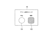
アラーム設定部18は、図2のように、アラームを希望するボタンであるアラーム申込151とアラーム希望を解除またはアラーム動作を解除するアラーム解除152との2個のスイッチを備え、各スイッチは、例えば照光式の押しボタンスイッチである。図2は、本実施形態におけるアラーム設定部18の一例を示す図である。また、アラーム設定部18は、アラーム設定(アラーム申込かアラーム解除か)指示信号をアラーム設定取得部19へ出力する。また、アラーム設定部18は、例えば、座席4に設置されている。
例えば、利用者は着駅を知らせるアラームを希望する場合、アラーム申込ボタン151を押してアラームを申し込む。さらに、アラーム希望を取り消したい場合やアラーム動作中にアラーム動作を解除したい場合、利用者はアラーム設定部18のアラーム解除ボタン152を押してアラーム動作の取り消し、または解除を行う。
As shown in FIG. 2, the
For example, when the user desires an alarm notifying the arrival station, the user applies an alarm by pressing the
アラーム設定取得部19は、アラーム設定部18が出力するアラーム設定指示信号を受け取り、受け取ったアラーム設定信号がアラーム申込かアラーム解除かを判定して、判定結果であるアラーム設定信号を制御部20に出力する。
The alarm
制御部20は、駅判定部17が出力する手前駅通過データまたは着駅通過データと、アラーム設定取得部19が出力するアラーム設定信号とを受け取る。また、制御部20は、アラーム申込のアラーム設定信号を受け取った後、手前駅通過データを受け取った場合、表示部21にアラーム状態ランプ(黄色)を点灯するアラーム表示信号を出力し、アラーム部22にアラーム動作を開始するアラーム動作信号を出力する。さらに、制御部20は、駅判定部17が出力する着駅通過データを受け取り、受け取った着駅通過データに基づき、アラーム状態ランプ(黄色)を消灯するアラーム表示信号を表示部21に出力し、アラーム部22にアラームを停止するアラーム動作信号を出力する。
The
表示部21(アラーム状態表示部)は、着信ランプ(緑色)と空席ランプ(赤色)とアラーム状態ランプ(黄色)とを備える。また、表示部21は、表示切り替え部15が出力する着空席ランプ信号と、制御部20が出力するアラーム表示信号を受け取り、受け取った各信号に基づき、着席ランプと空席ランプとアラーム状態ランプを点灯、または消灯する。
The display unit 21 (alarm status display unit) includes an incoming call lamp (green), an empty seat lamp (red), and an alarm status lamp (yellow). The
アラーム部22は、例えば、座席4に取り付けられているか、あるいは、座席4に埋め込まれている。また、アラーム部22は、制御部20が出力するアラーム動作信号に基づき、アラーム動作の開始と停止とを行う。なお、アラーム動作とは、例えば振動や音等により、着駅が近づいたことを利用者に注意喚起するものである。
The
図3は、本実施形態における座席4とICカード読み取り部11とアラーム設定部18と表示部21とアラーム部22との位置関係の一例を説明する図である。図3のように、アラーム部22は座席4に取り付けられており、アラーム設定部18は、座席4に取り付けられている。また、ICカード読み取り部11と表示部21は、各座席4の上部に設置されている。
図4は、本実施形態におけるICカード読み取り部11と表示部21の一例を示す図である。図4のように、ICカード読み取り・表示部100は、ICカード読み取り部11と表示部21が一体化していて、表示部21は着席ランプ(緑色)111とアラーム状態ランプ(黄色)112と空席ランプ(赤色)113を有している。
FIG. 3 is a diagram for explaining an example of a positional relationship among the
FIG. 4 is a diagram illustrating an example of the IC
次に、アラームとしてバイブレータ(振動子)を用いる例を、図5と図6を用いて説明する。図5は、本実施形態における座席と振動子位置の一例を示す図である。図5(a)に示すように、座席4を横から見た場合、バイブレータ(振動子)は、座席4に座る利用者が子供でも大人でも対応できる位置であることが望ましく、また、座る姿勢が異なっても振動が伝わることが望ましい。実験の結果、背もたれ部201と座面202には、それぞれ1つ以上の振動子を備えることが望ましい。また、図5(b)に示すように、座席4を正面から見た場合、バイブレータ(振動子)の取り付け位置は、中心部201A〜201Cや202A〜202Cのみではなく、201D、201E、202D、202Eのように左右でも良い。なお、図5(b)の左に示した図は、座席4を横から見たときのバイブレータの取り付け位置を示す図であり、図5(b)の右に示した図は、座席4を正面から見た図である。
さらに図5(c)に示すように、座席4の中心部には振動子を取り付けず、バイブレータ(振動子)の取り付け位置は、201F、201G、202F、202Gのように左右のみに取り付けても良い。
Next, an example in which a vibrator (vibrator) is used as an alarm will be described with reference to FIGS. FIG. 5 is a diagram illustrating an example of a seat and a vibrator position in the present embodiment. As shown in FIG. 5A, when the
Further, as shown in FIG. 5 (c), no vibrator is attached to the center of the
図6は、本実施形態における振動子と取り付け材料の検討結果の一例を示す図である。図6において、(1)プラ板〜(6)スポンジゴム(厚)+プラ板は、各素材を用いて小型振動子を取り付けた場合のアンケートによる評価結果である。また(7)は大型バイブレータを用いた場合の評価結果である。図6に示すように、7項目について、各々5段階評価を行った。評価は、1が悪く、5が良いことを表している。評価を行った項目は、バイブレータによる起きやすさ、バイブレータの静音性、バイブレータに対する異物感、バイブレータ実装の簡易性、バイブレータのメンテナンスの容易さ、取り付けコスト、総合評価である。使用した素材は、(1)プラ板、(2)段ボール、(3)薄いスポンジゴム、(4)薄いスポンジゴムにプラ板を合わせたもの、(5)厚いスポンジゴム、(6)厚いスポンジゴムにプラ板を合わせたものである。このような評価結果により、振動子の大きさや振動子を取り付ける素材を検討した結果、大型バイブレータを用いた場合、総合評価が高い結果が得られた。 FIG. 6 is a diagram illustrating an example of the examination result of the vibrator and the attachment material in the present embodiment. In FIG. 6, (1) plastic plate to (6) sponge rubber (thickness) + plastic plate are evaluation results based on a questionnaire when a small vibrator is attached using each material. Moreover, (7) is an evaluation result when a large vibrator is used. As shown in FIG. 6, each of the seven items was evaluated on a five-level scale. The evaluation shows that 1 is bad and 5 is good. Items evaluated were ease of getting up with the vibrator, quietness of the vibrator, foreign object feeling to the vibrator, simplicity of vibrator mounting, ease of maintenance of the vibrator, installation cost, and comprehensive evaluation. The materials used were (1) plastic board, (2) cardboard, (3) thin sponge rubber, (4) thin sponge rubber combined with plastic board, (5) thick sponge rubber, (6) thick sponge rubber. And a plastic plate. Based on such evaluation results, the size of the vibrator and the material for attaching the vibrator were examined. As a result, when a large vibrator was used, a high overall evaluation was obtained.
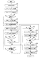
次に、アラーム動作手順を、図7と図8を用いて説明する。図7は、表示部の表示タイミングを説明する図である。図8は、アラーム動作手順のフローチャートである。以下は、特別乗車券としてグリーン券を用いる場合を例に説明する。まず、利用者は駅の自動券売機にICカード乗車券2を挿入し、希望する乗車区間(発駅、着駅)のグリーン券を購入する(ステップS1)。次に、自動券売機は、乗車区間と有効期間(例えば、発券した当日)を、グリーン券データとしてICカード乗車券2に書き込んで記憶させる(ステップS2)。
Next, the alarm operation procedure will be described with reference to FIGS. FIG. 7 is a diagram for explaining the display timing of the display unit. FIG. 8 is a flowchart of the alarm operation procedure. In the following, a case where a green ticket is used as a special ticket will be described as an example. First, the user inserts the
次に、利用者は希望する列車に発駅から乗車(図7;時刻t1)した後、空いている座席4上に設置されているICカード読み取り部11にグリーン券データが記憶されているICカード乗車券2をかざして読み取らせる。また、ICカード読み取り部11は、ICカード乗車券2から乗車区間データと特別乗車券の有効期限データ等を含む乗車券データを読み込む(ステップS3;乗車券データ読み取り工程)。また、座席4が空席の場合、座席4上の表示部21には、空席ランプ113のみが点灯している。他の利用者が使用している場合、座席4上の表示部21には、着席ランプ111が点灯している。
なお、表示部21の初期状態は、着席ランプ111は消灯、アラーム状態ランプ112は消灯、空席ランプ113は点灯である。
Next, after the user gets on the desired train from the departure station (FIG. 7; time t1), the IC in which the green ticket data is stored in the IC
In the initial state of the
次に、ICカード読み取り部11は、読み取った乗車券データを有効判定部12と着駅抽出部13に出力する。次に、有効判定部12は、駅データ取得部16が出力する駅データと、ICカード読み取り部11が出力する乗車券データを受け取る。乗車券データを受け取った後、有効判定部12は、受け取った乗車券データから乗車区間データと有効期限データを抽出する。乗車区間データと有効期限データを抽出した後、有効判定部12は、有効期限が有効か否かを判定し、また、乗車区間データと駅データを比較し乗車区間が有効か否かを判定する(ステップS4)。具体的には、有効判定部12は、利用者がグリーン券を購入した当日に乗車した場合、有効期間を有効と判定し、ICカード読み取り部11が、乗車データを読み出した時の駅データが乗車区間内でかつ進行方向が一致している場合、乗車区間を有効と判定する。また、利用者はICカード乗車券2をICカード読み取り部11に着席ランプ111が点灯するまでタッチし続ける。
Next, the IC
有効期間か乗車区間を有効ではないと判定した場合(ステップS4;No)、有効判定部12は、乗車券データの無効を示す判定結果データを表示切り替え部15に出力する。乗車券データの無効を示す判定結果データを受け取った後、表示切り替え部15は、空席ランプを点灯する着空席ランプ信号を表示部21に出力する。表示部21は、着空席ランプ信号を受け取り、受け取った着空席ランプ信号に応じて空席ランプ(赤色)113を点灯する(ステップS5)。
乗車券データが無効の場合、または、グリーン券を利用者が未購入の場合、車内の検札係は、利用者に対して検札を行う。検札係は、利用者が希望する乗車区間のグリーン券を、特別乗車券発券端末3を用いて発券する。さらに特別乗車券発券端末3は、発券した区間情報と座席情報を含む乗車券データとを乗車券データ受信部14に発信する(ステップS6)。
次に、乗車券データ受信部14は、特別乗車券発券端末3が発信する乗車券データを受信し、受信した乗車券データに基づき、乗車区間データを含む乗車券データを着駅抽出部13に出力し、乗車券有効データを含む乗車券データを表示切り替え部15に出力する。
When it is determined that the valid period or the boarding section is not valid (step S4; No), the
If the ticket data is invalid, or if the user has not purchased a green ticket, the ticket checker in the car checks the user. The ticket checker issues the green ticket of the boarding section desired by the user using the special
Next, the ticket
有効期間か乗車区間を有効であると判定した場合(ステップS4;Yes)、有効判定部12は、乗車券データの有効を示す判定結果データを表示切り替え部15に出力する。
When it is determined that the validity period or the boarding section is valid (step S4; Yes), the
次に、表示切り替え部15は、受け取った判定結果データに乗車券有効データが含まれている場合、着席ランプの点灯を指示する着空席ランプ信号を表示部21に出力する。着空席ランプ信号を受け取った後、表示部21は、受け取った着空席ランプ信号に基づき着席ランプを点灯し、空席ランプを消灯する(ステップS7、図7;時刻t2)。
Next, when the received determination result data includes ticket valid data, the
次に、着駅抽出部13は、ICカード読み取り部11が読み出した乗車券データから着駅名データを抽出し(着駅抽出工程)、抽出した着駅名データを駅判定部17に出力する。また、駅データ取得部16は、各駅に設置されている駅データを発信する装置が発信する駅データを受信し(駅データ取得工程)、受信した駅データを有効判定部12と駅判定部17とに出力する。
次に、利用者がアラームを希望する場合、利用者は座席4に取り付けられているアラーム設定部18のアラーム申込ボタン151を押してアラームを申し込む(図7;時刻t3)。
次に、アラーム設定取得部19は、アラーム設定部18が出力するアラーム設定指示信号を受け取り(ステップS8)、受け取ったアラーム設定指示信号がアラーム申込かアラーム解除かを判定する(ステップS9)。アラーム設定取得部19は、判定結果であるアラーム設定信号を制御部20に出力する。
Next, the arrival
Next, when the user desires an alarm, the user applies an alarm by pressing the
Next, the alarm setting
アラーム設定の申込が行われていない場合(ステップS9;No)、駅判定部17は着駅抽出部13が出力する着駅名データと駅データ取得部16が出力する駅データとを比較し、列車が判定時に走っている地点が着駅を過ぎているか否かを判定する(ステップS10)。着駅を過ぎていないと判定した場合(ステップS10;No)、ステップS8〜ステップS10を繰り返し、着駅を過ぎていると判定した場合(ステップS10;Yes)、ステップS18に進む。
If an application for alarm setting has not been made (step S9; No), the
アラーム設定の申込が行われている場合(ステップS9;Yes)、駅判定部17は着駅抽出部13が出力する着駅名データと駅データ取得部16が出力する駅データとを比較する。駅判定部17は、列車が着駅の1つ手前の駅を所定の距離、例えば50m通過したか否かを判定する(ステップS11;駅判定工程)。着駅の1つ手前の駅を所定の距離を通過していない場合(ステップS11;No)、ステップS8〜ステップS11を繰り返す。
If an application for alarm setting has been made (step S9; Yes), the
着駅の1つ手前の駅から所定距離を通過した場合(ステップS11;Yes)、駅判定部17は、着駅抽出部13が出力する着駅名データと駅データ取得部16が出力する駅データとを比較し、着駅を通過したか否かを判定する(ステップS12;駅判定工程)。
着駅を通過していない場合(ステップS12;No)、駅判定部17は、ステップS11の判定結果に基づき、手前駅通過データを制御部20に出力する。手前駅通過データを受け取った後、制御部20は、受け取った手前駅通過データに基づき、アラーム部22にアラーム動作を開始するアラーム動作信号を出力し、アラーム状態ランプ112(黄色)を点灯するアラーム表示信号を表示部21に出力する。アラーム部22は、制御部20が出力するアラーム動作信号を受け取り、受け取ったアラーム動作信号に応じてアラーム動作を開始する(ステップS13、図7;時刻t5)。さらに、表示部21は、制御部20が出力するアラーム表示信号を受け取り、受け取ったアラーム表示信号に応じて表示部21のアラーム状態ランプ112を点灯する(ステップS14)。
When a predetermined distance is passed from the station immediately before the destination station (step S11; Yes), the
If it has not passed through the arrival station (step S12; No), the
次に、制御部20は、アラーム設定取得部19が出力するアラーム設定信号を受け取り、受け取ったアラーム設定信号を用いてアラーム動作中にアラーム動作解除が行われたか否かを判定する(ステップS15)。アラーム解除が行われていない場合(ステップS15;No)、ステップS8に戻り、ステップS8〜ステップS15を繰り返す。
アラーム解除が行われた場合(ステップS15;Yes)、ステップS16に進む。
Next, the
When the alarm is released (step S15; Yes), the process proceeds to step S16.
着駅を通過した場合(ステップS12;Yes)、駅判定部17は、ステップS12の判定結果に基づき、着駅通過データを制御部20に出力する。また、アラーム動作中にアラーム動作解除が行われた場合(ステップS15;Yes、図7;時刻t6)、アラーム設定取得部19はアラーム設定信号を制御部20に出力する。
次に、制御部20は、受け取った着駅通過データ、またはアラーム設定信号に応じて、アラーム部22にアラーム動作を停止するアラーム動作信号を出力し、アラーム状態ランプ112を点灯するアラーム表示信号を表示部21に出力する。アラーム部22は、制御部20が出力するアラーム動作信号を受け取り、受け取ったアラーム動作信号に応じてアラーム動作を停止する(ステップS16)。さらに、表示部21は、制御部20が出力するアラーム表示信号を受け取り、受け取ったアラーム表示信号に応じて表示部21のアラーム状態ランプ112を消灯する(ステップS17)。
When passing through the arrival station (step S12; Yes), the
Next, the
次に、駅判定部17は、着駅通過データを表示切り替え部15に出力する。表示切り替え部15は、受け取った着駅通過データに基づき、着席ランプ111を消灯し空席ランプ113を点灯する着空席ランプ信号を生成し、生成した着空席ランプ信号を表示部21に出力する。次に、表示部21は、表示切り替え部15が出力する着空席ランプ信号を受け取り、受け取った着空席ランプ信号に基づき、着席ランプ111を消灯し空席ランプ113を点灯する(ステップS18、図7;時刻t7)。
以上でアラーム動作を終了する。
Next, the
This completes the alarm operation.
以上のように、ICカード読み取り部11は、ICカード乗車券2に記憶されている特別乗車券である乗車券データを読み取り、読み取った乗車券データから乗車区間データや有効期間データ等を読み取る。そして、アラームを使用したい場合、利用者は、アラーム設定部18のアラーム申込ボタン151を使ってアラーム動作の設定を行う。このアラーム動作の設定をアラーム設定取得部19が取得する。また、駅データ取得部16は、列車が通過する駅毎に駅データを取得し、さらに駅判定部17は、この駅データと乗車区間データを用いて、利用者が降車する着駅の1つ手前の駅を通過したか否かを検出するようにした。アラーム動作設定が行われていて且つ着駅の1つ手前の駅を所定の距離通過した場合、駅判定部17は、手前駅通過データを制御部20に出力し、制御部20は受け取った手前駅通過データに基づき、アラーム部22の動作を開始し、さらに表示部21のアラーム状態ランプ112にアラーム動作中を表示するようにした。この結果、本実施形態の着駅アラーム装置では、利用者が降車したい駅の1つ手前の駅を通過した時、座席4に設置されたアラーム部22が動作し、さらに表示部21のアラーム状態ランプを点灯することで利用者に降車駅が近づいたことを注意喚起して、乗り過ごしや寝過ごすことを防止することができるようになる。
As described above, the IC
また、本実施形態では、車両内の1つの座席4と1つの着駅アラーム装置1について説明したが、列車内には複数の座席4があり、各座席4に着駅アラーム装置1を有しても良く、または、1つの着駅アラーム装置1が、複数の座席の各アラーム部を動作するようにしても良い。
In this embodiment, one
[第2実施形態]
次に、第2実施形態について図9〜図11を用いて説明する。図9は、第2実施形態における着駅アラーム装置の構成の一例を示す図である。図10は、回転座席と表示部の一例を示す図である。図11は、座席回転による表示入れ替えの一例を説明する図である。第1実施形態と同一の機能部は同じ番号を用いて説明は省略する。着駅アラーム装置1aは、座席回転検出部301と、扉開閉データ取得部302とを、さらに備え、駅判定部303と制御部304の機能、および表示部21aが、第1実施形態の着駅アラーム装置1と異なっている。
[Second Embodiment]
Next, a second embodiment will be described with reference to FIGS. FIG. 9 is a diagram illustrating an example of the configuration of the arrival station alarm device according to the second embodiment. FIG. 10 is a diagram illustrating an example of the rotating seat and the display unit. FIG. 11 is a diagram illustrating an example of display switching by seat rotation. The same functional units as those in the first embodiment are denoted by the same reference numerals and description thereof is omitted. The arrival
座席回転検出部301は、座席4に取り付けられ、座席4の回転を検出し、検出結果に基づき座席回転検出信号を生成し、生成した座席回転検出信号を制御部304に出力する。
The seat
扉開閉データ取得部302は、列車の扉5の開閉状態を検出し、検出結果に基づき、扉開閉データを駅判定部303に出力する。
The door opening / closing
駅判定部303は、着駅抽出部13が出力する着駅名データと、表示切り替え部15が出力する着空席データと、駅データ取得部16が出力する駅データと、扉開閉データ取得部302が出力する扉開閉データとを受け取る。また、駅判定部303は、受け取った着駅名データと着空席データと駅データを用いて、着駅の1つ手前の駅を所定の距離(例えば50m)過ぎた場合、着駅の1つ手前の駅を通過したと判定し、判定した結果に基づき手前駅通過データを制御部304に出力する。さらに、駅データ判定部303は、受け取った駅データと着駅名データを比較し同一の場合、扉開閉データを受け取った後に着駅を通過したか否かを判定する。さらにまた、駅判定部303は、着駅を通過したと判定した場合、着駅通過データを表示切り替え部15と制御部304に出力する。
The
制御部304は、駅判定部303が出力する手前駅通過データと、駅判定部303が出力する着駅通過データと、アラーム設定取得部19が出力するアラーム設定信号と、座席回転検出部301が出力する座席回転検出信号を受け取る。また、制御部304は、アラーム申込のアラーム設定信号を受け取った後、手前駅通過データを受け取った場合、表示部21aにアラーム状態ランプ(黄色)112を点灯するアラーム表示信号を出力し、アラーム部22にアラーム動作を開始するアラーム動作信号を出力する。さらに、制御部304は、駅判定部303が出力する着駅通過データを受け取り、受け取った着駅通過データに基づき、アラーム状態ランプ(黄色)112を消灯するアラーム表示信号を表示部21aに出力し、アラーム部22にアラームを停止するアラーム動作信号を出力する。さらにまた、制御部304は、受け取った座席回転検出信号に応じて、表示位置入れ替え指示を表示部21aに出力する。
The
表示部21aは、窓際の座席4に関する着席や空席状態を表示する表示部と、通路側の座席4に関する着席や空席状態を表示する表示部とを備え、例えば、図10(a)および図10(b)のように、座席4上部に設置されている。図10は、本実施形態に係る回転座席と表示部の一例を示す図である。また、図10(a)および図10(b)は、座席4を車両の上側から見た図である。また、表示部21aは、制御部304が出力する表示位置入れ替え指示に応じて、窓側の座席に対応する表示と通路側の座席に対応する表示とを入れ替える。
The
次に、着駅アラーム装置1aの動作について、図10と図11を用いて説明する。図11は、本実施形態に係る座席回転による表示入れ替えの一例を説明する図である。図11(a)のように、ICカード読み取り部11と表示部21aが一体化しているICカード読み取り・表示部100aおよびICカード読み取り・表示部100bが座席4上に設置されているとして説明する。また、図10において、右側を進行方向とする。
例えば、初期状態における座席4(4A、4B)は、図10(a)に示すように進行方向の向きである。また、図10(a)に示すように、座席回転検出部301は、例えば、窓側の座席4Aの進行方向の座部に設置され、通路側の座席4Bの背もたれの後ろに設置されている。図10において、座席4Aおよび座席4Bの斜線部は背もたれを表し、白の部分は座部を表している。
図10(a)の状態の時に、窓際の座席4Aに利用者が乗車し、ICカード読み取り部11にICカード乗車券2を接触させてデータを読み込ませる。この結果、制御部304は、第1実施形態と同様に、ICカード乗車券2から取得したデータ、駅データ等に基づき、乗車券データが有効な場合、ICカード読み取り・表示部100aの着席ランプを点灯させる。
Next, operation | movement of the arrival
For example, the seat 4 (4A, 4B) in the initial state is in the traveling direction as shown in FIG. Further, as shown in FIG. 10A, the seat
In the state of FIG. 10A, the user gets on the seat 4A near the window, and the IC
図10(a)の状態から図10(b)の状態に、利用者が一体化している座席4Aと座席4Bの向きを進行方向に対して180度回転した場合、従来はICカード読み取り・表示部100aの着席ランプが表示されたままで、ICカード読み取り・表示部100bの着席ランプは消灯のままであった。このような使用方法でも、利用者が空席ランプの点灯しているICカード読み取り・表示部100aかICカード読み取り・表示部100bにICカード乗車券をタッチしてデータを読み取らせて使用しても支障はなかった。しかしながら、ICカード読み取り・表示部100に表示する情報にアラーム状態も関係しているため、座席の方向を切り替えた後、ICカード読み取り・表示部100aと100bの表示を入れ替える必要がある。
When the direction of the seat 4A and the seat 4B in which the user is integrated is rotated 180 degrees with respect to the traveling direction from the state of FIG. 10A to the state of FIG. The seating lamp of the IC card reading /
このため、本実施形態に係る着駅アラーム装置1aでは、図10(a)のように座席4に座席回転検出部301を取り付け、座席4の回転を検出する。座席回転検出部301は、例えば、機械式スイッチである。座席4が回転された後、座席回転検出部301は、座席4の回転を検出し、検出結果に基づき座席回転検出信号を生成し、生成した座席回転検出信号を制御部304に出力する。座席回転検出信号を受け取った後、制御部304は、受け取った座席回転検出信号に応じて、表示位置入れ替え指示を表示部21に出力する。表示位置入れ替え指示を受け取った後、表示部21は、座席4の回転にともないICカード読み取り・表示部100aおよびICカード読み取り・表示部100bの表示状態を入れ替える。
For this reason, in the arrival
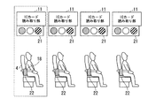
具体的な例を、図11を用いて説明する。図11(a)と図11(c)が座席4を回転させる前の表示状態であり、図11(b)と図(d)が座席4を回転させた後の表示上他を表している。図11(a)と図11(c)に示すように、座席4を回転させる前の表示状態は、左側のICカード読み取り・表示部100aが窓側の座席4Aに対応し、ICカード読み取り・表示部100bが通路側の座席4Bに対応している。
まず、図11(a)と図11(c)に示すように、座席4の回転後の表示関係は、窓際の座席4Aが着席のため、ICカード読み取り・表示部100aの着席ランプ111aが点灯し、通路側の座席4Bが空席のため、ICカード読み取り・表示部100bの空席ランプ113bが点灯している。座席4を回転させた後、図11(a)の表示から図11(b)の表示ように「窓側」と「通路側」の表示位置関係を入れ替える。すなわち、図11(b)に示すように、座席4の回転後の表示関係は、ICカード読み取り・表示部100aが通路側の座席4Aの状態を表示し、ICカード読み取り・表示部100bが窓側の座席4Bの状態を表示する。このため、ICカード読み取り・表示部100aは、着席ランプ111aが点灯し、空席ランプ113aが消灯した状態を維持する。また、また、ICカード読み取り・表示部100bは、着席ランプ111aが消灯し、空席ランプ113aが点灯した状態を維持する。
または、座席4を回転させた後、図11(c)の表示から図11(d)の表示のように、表示部21とICカード読み取り部11と、座席4Aと座席4Bとの対応関係を入れ替える。すなわち、図11(d)に示すように、座席4の回転後の表示関係は、ICカード読み取り・表示部100aが窓側の座席4Bの状態を表示し、ICカード読み取り・表示部100bが通路側の座席4Aの状態を表示する。このため、ICカード読み取り・表示部100aは、着席ランプ111aが消灯し、空席ランプ113aが点灯する。また、ICカード読み取り・表示部100bは、着席ランプ111aが点灯し、空席ランプ113aが消灯する。
A specific example will be described with reference to FIG. FIGS. 11A and 11C show the display state before the
First, as shown in FIGS. 11 (a) and 11 (c), the display relationship after the rotation of the
Alternatively, after the
以上のように、座席4の回転に伴い、ICカード読み取り部11と表示部21との位置関係、または表示を座席に対応させて入れ替えるようにしたので、ICカード読み取り部11にICカード乗車券2を読み取らせた後に座席4を回転させても、適正な着席表示と空席表示およびアラーム状態を表示することができる。この結果、利用者にアラームの動作状態や着駅に近づいたことを適正に注意喚起することができるので、寝過ごしや乗り過ごしを防ぐことができる。
As described above, as the
また、本実施形態では、特別乗車券を駅の自動券売機で購入し、利用者が所持するICカード乗車券2に特別乗車券データを書き込んで記録させる例を説明したが、ICカードを内蔵している携帯電話でも良く、この場合、携帯電話から電話回線を介しネットワーク経由で直接、特別乗車券を購入してICカードに乗車券データを書き込んで記録するようにしても良い。
In the present embodiment, an example in which a special ticket is purchased at an automatic ticket vending machine at a station and the special ticket data is written and recorded in the
また、本実施形態では、着駅の1つ手前の駅を所定の距離通過した場合、駅判定部17または駅判定部303が手前駅通過データを出力する例を説明したが、駅判定部17または駅判定部303は、着駅の1つ手前の駅から駅データ受信後、所定の時間が経過した後に手前駅通過データを出力するようにしても良い。また、駅と駅の乗車時間が短い場合、駅判定部17または駅判定部303は、着駅より1つ前の停車駅を出発した時に手前駅通過データを出力するようにしても良い。
Further, in the present embodiment, the example in which the
また、本実施形態では、駅データ取得部16が、各駅に設置してある駅データ発信装置が発信する駅データを受信する例を説明した。他の例として、駅データ取得部16は、図示しない車両内に設置されている列車運行状態を管理する装置が生成する第2駅データを取得し、取得した第2駅データを駅判定部17に出力するようにしても良い。また、駅データ取得部16は、駅情報発信装置が発信する駅データと第2駅データの両方を用いても良く、例えば、受信した駅データを用いて第2駅データの同期を行うようにしても良い。
Moreover, in this embodiment, the station
また、本実施形態では、アラーム設定部18に押しボタンスイッチを用いる例を説明したが、使用するスイッチは、スライドスイッチ等の他のスイッチでも良く、また、アラーム申込ボタン151とアラーム解除ボタン152は1つのトグルスイッチを用いても良い。
In this embodiment, an example in which a push button switch is used for the
また、本実施形態では、制御部20がアラーム部22に着駅手前から利用者がアラーム解除を行うまでアラーム動作を連続して行う例を説明した。他の例として、例えば、一般的な目覚まし時計のように、アラームを所定時間動作した後にアラーム動作を停止し、アラーム動作の解除が行われていない場合、制御部20は、所定時間経過後に再度アラーム動作を繰り返すように制御しても良い。
Further, in the present embodiment, an example has been described in which the
また、本実施形態では、図4のような着席ランプ(緑色)111とアラーム状態ランプ(黄色)112と空席ランプ(赤色)113の配置例を示したが、表示ランプの配置は、図4の配置順番または配置に限らず、また点灯するランプの色もこれに限られない。さらに、ICカード読み取り部11と表示部21の設置箇所として、座席4の上部に設置する例を説明したが、設置箇所は、例えば座席の膝置き等に設置しても良い。
Further, in this embodiment, the arrangement example of the seating lamp (green) 111, the alarm state lamp (yellow) 112, and the vacant seat lamp (red) 113 as shown in FIG. 4 is shown, but the arrangement of the display lamp is as shown in FIG. It is not limited to the arrangement order or arrangement, and the color of the lamp to be lit is not limited to this. Furthermore, although the example which installs in the upper part of the
また、本実施形態では、アラーム設定が申し込まれている場合、アラーム部22の動作(振動等)と表示部21の表示を行う例を説明したが、アラーム設定が行われていない場合においても、着駅の1つ手前の駅を所定の距離過ぎた後、制御部20は、表示部21のアラーム状態ランプ112を点灯するよう制御しても良い。
Further, in the present embodiment, when the alarm setting is applied, the example of performing the operation (vibration, etc.) of the
なお、実施形態の図1または図9の各部の機能を実現するためのプログラムをコンピュータ読み取り可能な記録媒体に記録して、この記録媒体に記録されたプログラムをコンピュータシステムに読み込ませ、実行することにより各部の処理を行ってもよい。なお、ここでいう「コンピュータシステム」とは、OSや周辺機器等のハードウェアを含むものとする。
また、「コンピュータシステム」は、WWWシステムを利用している場合であれば、ホームページ提供環境(あるいは表示環境)も含むものとする。
また、「コンピュータ読み取り可能な記録媒体」とは、フレキシブルディスク、光磁気ディスク、ROM(Read Only Memory)、CD−ROM等の可搬媒体、USB(Universal Serial Bus) I/F(インタフェース)を介して接続されるUSBメモリー、コンピュータシステムに内蔵されるハードディスク等の記憶装置のことをいう。さらに「コンピュータ読み取り可能な記録媒体」とは、インターネット等のネットワークや電話回線等の通信回線を介してプログラムを送信する場合の通信線のように、短時間の間、動的にプログラムを保持するもの、その場合のサーバやクライアントとなるコンピュータシステム内部の揮発性メモリーのように、一定時間プログラムを保持しているものも含むものとする。また上記プログラムは、前述した機能の一部を実現するためのものであっても良く、さらに前述した機能をコンピュータシステムにすでに記録されているプログラムとの組み合わせで実現できるものであっても良い。
Note that a program for realizing the functions of the respective units in FIG. 1 or FIG. 9 of the embodiment is recorded on a computer-readable recording medium, and the program recorded on the recording medium is read into a computer system and executed. You may process each part by. Here, the “computer system” includes an OS and hardware such as peripheral devices.
Further, the “computer system” includes a homepage providing environment (or display environment) if a WWW system is used.
The “computer-readable recording medium” is a portable medium such as a flexible disk, a magneto-optical disk, a ROM (Read Only Memory), a CD-ROM, or a USB (Universal Serial Bus) I / F (interface). A storage device such as a USB memory or a hard disk built in a computer system. Furthermore, the “computer-readable recording medium” dynamically holds a program for a short time like a communication line when transmitting a program via a network such as the Internet or a communication line such as a telephone line. In this case, it also includes those that hold a program for a certain period of time, such as a volatile memory inside a computer system serving as a server or client in that case. The program may be a program for realizing a part of the functions described above, and may be a program capable of realizing the functions described above in combination with a program already recorded in a computer system.
1・・・着駅アラーム装置
2・・・ICカードを内蔵した乗車券
11・・・ICカード読み取り部
12・・・有効判定部
13・・・着駅抽出部
14・・・乗車券データ受信部
15・・・表示切り替え部
16・・・駅データ取得部
17・・・駅判定部
18・・・アラーム設定部
19・・・アラーム設定取得部
20・・・制御部
21・・・表示部
22・・・アラーム部
DESCRIPTION OF
Claims (4)
前記乗車券データ読み取り部が読み取った乗車区間情報から着駅名データを抽出する着駅抽出部と、
車両が通過または停止した駅データを取得する駅データ取得部と、
前記着駅抽出部が抽出した前記着駅名データと前記駅データ取得部が取得した前記駅データとを用いて、
前記着駅より前の所定の距離または前記着駅に着く前の所定の時刻で手前駅判定信号を生成する駅判定部と、
を備え、
前記手前駅判定信号を受けてアラーム動作することを特徴とする着駅アラーム装置。 A ticket data reading unit for reading a boarding section from a ticket in which the boarding section is recorded;
Arrival station extraction unit that extracts arrival station name data from the boarding section information read by the ticket data reading unit,
A station data acquisition unit for acquiring station data where the vehicle has passed or stopped;
Using the arrival station name data extracted by the arrival station extraction unit and the station data acquired by the station data acquisition unit,
A station determination unit that generates a near station determination signal at a predetermined distance before the arrival station or at a predetermined time before arrival at the arrival station;
With
An arrival station alarm device that receives the near station determination signal and performs an alarm operation.
前記アラーム動作を表示するアラーム状態表示部と
をさらに備え、
前記アラーム設定部の設定がアラーム申込の設定の場合、
前記手前駅判定信号を受けて、前記アラーム状態表示部に前記アラーム状態を表示すことを特徴とする請求項1に記載の着駅アラーム装置。 An alarm setting section for setting an alarm application to notify the arrival station or setting an alarm release;
An alarm state display unit for displaying the alarm action,
When the setting of the alarm setting part is the setting of alarm application,
2. The arrival station alarm device according to claim 1, wherein upon receiving the near station determination signal, the alarm state is displayed on the alarm state display unit.
さらに備え、
前記座席回転検出部が前記座席の回転を検出した場合、
座席の回転に応じて前記アラーム状態表示部の表示位置を切り替えることを特徴とする請求項2に記載の着駅アラーム装置。 A seat rotation detection unit that detects rotation of the seat with respect to a traveling direction;
In addition,
When the seat rotation detection unit detects the rotation of the seat,
The arrival station alarm device according to claim 2, wherein the display position of the alarm state display unit is switched according to the rotation of the seat.
着駅抽出部が、前記乗車券データ読み取り工程が読み取った乗車区間情報から着駅名データを抽出する着駅抽出工程と、
駅データ取得部が、車両が通過または停止した駅データを取得する駅データ取得工程と、
駅判定部が、前記着駅抽出工程が抽出した前記着駅名データと前記駅データ取得工程が取得した前記駅データとを用いて、前記着駅より前の所定の距離または前記着駅に着く前の所定の時刻で手前駅判定信号を生成する駅判定工程と、
を備え、
前記手前駅判定信号を受けてアラーム動作することを特徴とする着駅アラーム方法。 A ticket data reading step for reading a boarding section from a ticket in which the boarding section is recorded;
The arrival station extraction unit extracts the arrival station name data from the boarding section information read by the ticket data reading step, and
The station data acquisition unit acquires station data where the vehicle has passed or stopped,
The station determination unit uses the destination station name data extracted in the arrival station extraction step and the station data acquired in the station data acquisition step, or a predetermined distance before the arrival station or before arriving at the arrival station. A station determination step of generating a near station determination signal at a predetermined time,
With
An arrival station alarm method, wherein an alarm operation is performed in response to the near station determination signal.
Priority Applications (1)
| Application Number | Priority Date | Filing Date | Title |
|---|---|---|---|
| JP2010253353A JP2012103993A (en) | 2010-11-12 | 2010-11-12 | Destined station reminding device and destined station reminding method |
Applications Claiming Priority (1)
| Application Number | Priority Date | Filing Date | Title |
|---|---|---|---|
| JP2010253353A JP2012103993A (en) | 2010-11-12 | 2010-11-12 | Destined station reminding device and destined station reminding method |
Publications (1)
| Publication Number | Publication Date |
|---|---|
| JP2012103993A true JP2012103993A (en) | 2012-05-31 |
Family
ID=46394284
Family Applications (1)
| Application Number | Title | Priority Date | Filing Date |
|---|---|---|---|
| JP2010253353A Pending JP2012103993A (en) | 2010-11-12 | 2010-11-12 | Destined station reminding device and destined station reminding method |
Country Status (1)
| Country | Link |
|---|---|
| JP (1) | JP2012103993A (en) |
Cited By (7)
| Publication number | Priority date | Publication date | Assignee | Title |
|---|---|---|---|---|
| JP2013181820A (en) * | 2012-03-01 | 2013-09-12 | Toyota Motor Corp | Sleep control device |
| CN105620356A (en) * | 2015-12-24 | 2016-06-01 | 宁德市睿迅电子商务有限公司 | System and method for prompting vehicle arrival |
| JP2016536203A (en) * | 2013-08-26 | 2016-11-24 | ▲劉▼健 | Trains and train systems longer than home |
| CN106603816A (en) * | 2016-11-22 | 2017-04-26 | 大唐微电子技术有限公司 | Terminal reminding method and mobile terminal |
| JP2020050245A (en) * | 2018-09-28 | 2020-04-02 | コイト電工株式会社 | Seat device, seat control system and seat control method |
| CN112216140A (en) * | 2020-09-18 | 2021-01-12 | 华为技术有限公司 | Vehicle arrival confirmation method, electronic device, and computer-readable storage medium |
| CN115862068A (en) * | 2022-12-06 | 2023-03-28 | 北京崇迅科技有限公司 | Computer data information processing method and system based on big data |
Citations (7)
| Publication number | Priority date | Publication date | Assignee | Title |
|---|---|---|---|---|
| JPH03217999A (en) * | 1990-01-23 | 1991-09-25 | Shibaura Eng Works Co Ltd | Seat control system |
| JPH06309324A (en) * | 1993-04-27 | 1994-11-04 | East Japan Railway Co | On-train display device |
| JP2002271251A (en) * | 2001-03-09 | 2002-09-20 | Sharp Corp | In-vehicle information communication method of communication equipment in vehicle using its method, and electronic railroad ticket |
| JP2004021885A (en) * | 2002-06-20 | 2004-01-22 | Toshiba Corp | Guiding system and guiding method |
| JP2006069427A (en) * | 2004-09-03 | 2006-03-16 | Sharp Corp | Ion control vehicle |
| JP2007323123A (en) * | 2006-05-30 | 2007-12-13 | Kyocera Corp | Incorrect boarding prevention system and incorrect boarding prevention method |
| JP2009295055A (en) * | 2008-06-06 | 2009-12-17 | Rohm Co Ltd | Mobile equipment |
-
2010
- 2010-11-12 JP JP2010253353A patent/JP2012103993A/en active Pending
Patent Citations (7)
| Publication number | Priority date | Publication date | Assignee | Title |
|---|---|---|---|---|
| JPH03217999A (en) * | 1990-01-23 | 1991-09-25 | Shibaura Eng Works Co Ltd | Seat control system |
| JPH06309324A (en) * | 1993-04-27 | 1994-11-04 | East Japan Railway Co | On-train display device |
| JP2002271251A (en) * | 2001-03-09 | 2002-09-20 | Sharp Corp | In-vehicle information communication method of communication equipment in vehicle using its method, and electronic railroad ticket |
| JP2004021885A (en) * | 2002-06-20 | 2004-01-22 | Toshiba Corp | Guiding system and guiding method |
| JP2006069427A (en) * | 2004-09-03 | 2006-03-16 | Sharp Corp | Ion control vehicle |
| JP2007323123A (en) * | 2006-05-30 | 2007-12-13 | Kyocera Corp | Incorrect boarding prevention system and incorrect boarding prevention method |
| JP2009295055A (en) * | 2008-06-06 | 2009-12-17 | Rohm Co Ltd | Mobile equipment |
Cited By (9)
| Publication number | Priority date | Publication date | Assignee | Title |
|---|---|---|---|---|
| JP2013181820A (en) * | 2012-03-01 | 2013-09-12 | Toyota Motor Corp | Sleep control device |
| JP2016536203A (en) * | 2013-08-26 | 2016-11-24 | ▲劉▼健 | Trains and train systems longer than home |
| CN105620356A (en) * | 2015-12-24 | 2016-06-01 | 宁德市睿迅电子商务有限公司 | System and method for prompting vehicle arrival |
| CN106603816A (en) * | 2016-11-22 | 2017-04-26 | 大唐微电子技术有限公司 | Terminal reminding method and mobile terminal |
| JP2020050245A (en) * | 2018-09-28 | 2020-04-02 | コイト電工株式会社 | Seat device, seat control system and seat control method |
| JP7197320B2 (en) | 2018-09-28 | 2022-12-27 | コイト電工株式会社 | SEAT DEVICE, SEAT CONTROL SYSTEM AND SEAT CONTROL METHOD |
| CN112216140A (en) * | 2020-09-18 | 2021-01-12 | 华为技术有限公司 | Vehicle arrival confirmation method, electronic device, and computer-readable storage medium |
| CN115862068A (en) * | 2022-12-06 | 2023-03-28 | 北京崇迅科技有限公司 | Computer data information processing method and system based on big data |
| CN115862068B (en) * | 2022-12-06 | 2023-10-13 | 中软国际科技服务有限公司 | Big data-based computer data information processing method and system |
Similar Documents
| Publication | Publication Date | Title |
|---|---|---|
| JP2012103993A (en) | Destined station reminding device and destined station reminding method | |
| JP2009002088A (en) | Washroom facility utilization information management system, information processor, washroom facility utilization information management method, and control program | |
| JP4744216B2 (en) | Mobile device, service providing system, information communication terminal | |
| KR101868321B1 (en) | Public transportation smart roarding and alighting management system | |
| JP2013200699A (en) | Information distribution system, server device, information distribution method and program | |
| KR20160093205A (en) | Bus taking alam machine of the low bottom bus for disabled person | |
| CN107430005A (en) | Mobile message provides method, mobile message provides device and mobile message provides program | |
| KR20190064768A (en) | Reserved seat alert system for public transportation | |
| CN204432463U (en) | Bus is got off mutual alarm set | |
| JP2010100125A (en) | Control device and control method | |
| JP2000142408A (en) | Portable information apparatus | |
| CN203397518U (en) | Taxi calling system and calling terminal | |
| JP2016038858A (en) | Portable terminal device, program, and beacon management device | |
| JP2007323123A (en) | Incorrect boarding prevention system and incorrect boarding prevention method | |
| KR20180039300A (en) | System for protecting rights of the physical weak in public transport | |
| JP2548393B2 (en) | Override prevention device | |
| JP2850296B2 (en) | Seat management system | |
| JP2007182168A (en) | Notification system, computer used therefor, notification method and program | |
| GB2450689A (en) | Indicator module for passenger areas in public transport | |
| JP2004136703A (en) | Priority seat user notifying system, method and program | |
| JP3175496U (en) | Route guidance device | |
| JP2002067959A (en) | Public transportation riding past preventing system | |
| JP7412252B2 (en) | Payment terminal and payment processing system | |
| JP2001331605A (en) | Travel guide system using ic card and the same ic card | |
| JP2006107154A (en) | Vehicle use support system |
Legal Events
| Date | Code | Title | Description |
|---|---|---|---|
| A621 | Written request for application examination |
Free format text: JAPANESE INTERMEDIATE CODE: A621 Effective date: 20131112 |
|
| A977 | Report on retrieval |
Free format text: JAPANESE INTERMEDIATE CODE: A971007 Effective date: 20140917 |
|
| A131 | Notification of reasons for refusal |
Free format text: JAPANESE INTERMEDIATE CODE: A131 Effective date: 20140924 |
|
| A02 | Decision of refusal |
Free format text: JAPANESE INTERMEDIATE CODE: A02 Effective date: 20150303 |