JP2012068024A - Differential refractometer - Google Patents
Differential refractometer Download PDFInfo
- Publication number
- JP2012068024A JP2012068024A JP2010210348A JP2010210348A JP2012068024A JP 2012068024 A JP2012068024 A JP 2012068024A JP 2010210348 A JP2010210348 A JP 2010210348A JP 2010210348 A JP2010210348 A JP 2010210348A JP 2012068024 A JP2012068024 A JP 2012068024A
- Authority
- JP
- Japan
- Prior art keywords
- cell
- measurement light
- sample
- flow cell
- optical axis
- Prior art date
- Legal status (The legal status is an assumption and is not a legal conclusion. Google has not performed a legal analysis and makes no representation as to the accuracy of the status listed.)
- Pending
Links
Images

Abstract
Description
本発明は、液体クロマトグラフなどの分析装置において試料成分を検出する検出器として用いられる示差屈折率計に関するものである。 The present invention relates to a differential refractometer used as a detector for detecting a sample component in an analyzer such as a liquid chromatograph.
示差屈折率計は、測定光の光軸に対して傾斜した隔壁で仕切られた2つのセルからなるフローセルを備えている。フローセルの一方のセルは試料溶液を流通させるための試料セルであり、他方のセルは参照溶液を流通させるための参照セルである。さらに、フローセルを通過して屈折した測定光を測定光を受光する受光素子と、スリットを介して測定光をフローセルに照射し、フローセルからの測定光を受光素子へ導き、受光素子上にスリットの像を結像させる光学系が設けられている。 The differential refractometer includes a flow cell composed of two cells separated by a partition inclined with respect to the optical axis of the measurement light. One cell of the flow cell is a sample cell for circulating the sample solution, and the other cell is a reference cell for circulating the reference solution. Furthermore, the measurement light refracted through the flow cell is received by the light receiving element that receives the measurement light, and the measurement light is irradiated to the flow cell through the slit, the measurement light from the flow cell is guided to the light receiving element, An optical system for forming an image is provided.
示差屈折率計では、フローセルの試料セル内を試料成分が通過すると、試料セル内の屈折率が変化し、それによってフローセルを通過する測定光の経路が変化して受光素子上に結像されるスリット像が変位するので、その変位量を検出することにより、試料溶液の屈折率変化を検出して試料セルを通過する試料成分を検出することができる(特許文献1参照。)。 In the differential refractometer, when the sample component passes through the sample cell of the flow cell, the refractive index in the sample cell changes, thereby changing the path of the measurement light passing through the flow cell and forming an image on the light receiving element. Since the slit image is displaced, by detecting the displacement amount, it is possible to detect a change in the refractive index of the sample solution and to detect the sample component passing through the sample cell (see Patent Document 1).
図6は従来の示差屈折率計のフローセルの一例を示す図であり、(A)は入口部分における横断面図、(B)は出口部分における横断面図である。
フローセル30は、測定光の光軸に対して傾斜した隔壁30aによって仕切られた2つのセル32a,32bを備えている。セル32a,32bは同一の三角形断面をもち、各セル32a,32bには入口34a,36aと出口34b,36bが設けられている。セル32aは参照溶液を流通させる参照セルであり、セル32bは試料溶液を流通させる試料セルである。
6A and 6B are diagrams showing an example of a flow cell of a conventional differential refractometer, where FIG. 6A is a cross-sectional view at an entrance portion, and FIG. 6B is a cross-sectional view at an exit portion.
The
試料セル32bの断面形状が三角形であるため、試料セル32bを流れる試料溶液の濃度にある程度のムラが生じる。しかし、これまでの測定条件では、測定への濃度ムラの影響は無視できる程度に小さいものであった。近年、示差屈折率計では、試料セル中で流す試料の流量を低流量にしたいという要求がある。試料セル32b内で流す試料の流量を低流量にすると、試料セル32bの三角形断面によって生じる濃度ムラが大きくなり、その影響で正確な測定を行なうことができなくなることがわかった。具体的には、試料溶液の濃度は、断面中央部で最も高くなり、鋭角部近傍でそれよりも低くなる。測定光の通過領域で濃度ムラがあると測定光が試料溶液中で屈折してしまい、受光素子上に結像される測定光のスリット像の位置が本来の位置からずれる。
Since the cross-sectional shape of the
そこで本発明は、試料セルの形状に起因して発生する試料溶液の濃度ムラが測定に与える影響を小さくすることを目的とするものである。 SUMMARY OF THE INVENTION Accordingly, an object of the present invention is to reduce the influence of sample solution concentration unevenness caused by the shape of a sample cell on measurement.
本発明にかかる示差屈折率計は、測定光を発する光源と、同一の三角形断面をもち測定光の光軸に対して垂直な面をもつ試料セルと参照セルが測定光の光軸に対して傾斜した隔壁によって仕切られているとともに隔壁を軸として対称に配置され、両セルの入口及び出口が隔壁の測定光に対して垂直な面と隔壁との間の鋭角部近傍に光軸に対して垂直に設けられているフローセルと、フローセルを経た測定光を受光するための受光素子と、測定光をフローセルを透過させてから受光素子に導く光学系と、を備えたものである。 The differential refractometer according to the present invention includes a light source that emits measurement light, a sample cell having the same triangular cross-section and a plane perpendicular to the optical axis of the measurement light, and a reference cell with respect to the optical axis of the measurement light. Partitioned by inclined partition walls and symmetrically arranged with the partition walls as axes, the inlet and outlet of both cells are in the vicinity of an acute angle portion between the surface perpendicular to the partition wall measurement light and the partition walls with respect to the optical axis. A flow cell provided vertically, a light receiving element for receiving measurement light that has passed through the flow cell, and an optical system that guides the measurement light to the light receiving element after passing through the flow cell.
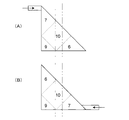
図4はフローセルの横断面における濃度分布を模式的に示す図であり、(A)は従来の示差屈折率計のフローセル、(B)は本発明の示差屈折率計のフローセルである。なお、図4における濃度領域は概略的に示したものであり、また、各領域の値も概算値である。 4A and 4B are diagrams schematically showing the concentration distribution in the cross section of the flow cell. FIG. 4A is a flow cell of a conventional differential refractometer, and FIG. 4B is a flow cell of the differential refractometer of the present invention. In addition, the density | concentration area | region in FIG. 4 is shown schematically, and the value of each area | region is also an approximate value.
図6にも示されているように、従来のフローセルでは、作成が容易であるため、流体の入口及び出口が測定光の光軸に平行な面のその面と隔壁との間の鋭角部の近傍に、測定光の光軸に対して垂直に設けられていた。この場合の濃度分布は、図4(A)に示されているように、最も高濃度の中央部を10とすると、入口及び出口が設けられている鋭角部近傍は7程度、鈍角部(ここでは90度)は9程度、入口及び出口とは反対側の鋭角部近傍は6程度となる。この状態で測定光が通過するセル中央部に濃度が10の領域と6の領域が存在してしまい、両領域の境界で測定光が屈折し、その結果、受光素子に結像される測定光が本来の位置からずれてしまう。 As shown also in FIG. 6, in the conventional flow cell, since it is easy to make, the inlet and outlet of the fluid are at an acute angle portion between the plane parallel to the optical axis of the measurement light and the partition wall. It was provided in the vicinity perpendicular to the optical axis of the measurement light. As shown in FIG. 4 (A), the concentration distribution in this case is about 7 in the vicinity of the acute angle portion where the inlet and the outlet are provided, and the obtuse angle portion (here 90 degrees) is about 9, and the vicinity of the acute angle portion on the side opposite to the inlet and outlet is about 6. In this state, a region having a density of 10 and a region having a concentration of 6 exist in the central portion of the cell through which the measurement light passes, and the measurement light is refracted at the boundary between both regions. As a result, the measurement light is imaged on the light receiving element. Will deviate from its original position.
上記の従来の例に対して、本発明では、セルの断面形状によって生じる試料の濃度ムラが小さくなるように、各セルの入口及び出口の位置を規定した。すなわち、測定光に対して垂直な面と隔壁に面する面との間の鋭角部に測定光に対して垂直に入口及び出口を配置した。図4(B)に具体的に示すと、本発明では、従来入口及び出口が設けられていた鋭角部とは反対側に位置する鋭角部の近傍に入口と出口を設けている。これにより、セル断面における濃度分布は、最も高濃度の中央部を10とすると、入口及び出口が設けられている鋭角部近傍は7程度、鈍角部は9程度、入口及び出口とは反対側の鋭角部近傍は6程度となり、中央部を通過する測定光は濃度が10の領域と7の領域を通過することになる。したがって、従来よりも測定光の通過領域における試料溶液の濃度ムラが小さくなり、測定光が試料溶液中で屈折しにくくなるため、測定精度が向上する。
In contrast to the above-described conventional example, in the present invention, the positions of the inlet and outlet of each cell are defined so that the density unevenness of the sample caused by the cross-sectional shape of the cell is reduced. That is, the entrance and the exit are arranged perpendicular to the measurement light at an acute angle portion between the surface perpendicular to the measurement light and the surface facing the partition wall. Specifically, in FIG. 4B, in the present invention, the inlet and the outlet are provided in the vicinity of the acute angle portion located on the opposite side to the acute angle portion where the conventional inlet and outlet are provided. As a result, the concentration distribution in the cell cross section indicates that the central portion of the highest concentration is 10, the vicinity of the acute angle portion where the inlet and the outlet are provided is about 7, the obtuse angle portion is about 9, and the opposite side of the inlet and the outlet. The vicinity of the acute angle portion is about 6, and the measurement light passing through the central portion passes through the region of
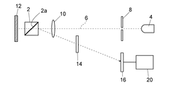
以下に示差屈折率計の一実施例について説明する。図1は一実施例の示差屈折率計を示す概略構成図である。
フローセル2がスリット8を介して入射する光源4からの測定光6の光軸上に配置されている。フローセル2は隔壁2aによって仕切られた2つのセルをもつ。一方のセルは試料溶液を流通させるための試料セルであり、他方のセルは参照溶液を流通させるための参照セルである。
An embodiment of the differential refractometer will be described below. FIG. 1 is a schematic configuration diagram showing a differential refractometer of one embodiment.
The
フローセル2の前方にはレンズ10が配置され、後方にフローセル2を透過した光を反射させるミラー12が配置されている。ミラー12により反射された測定光の光路上に受光素子16が設けられており、ミラー12で反射してフローセル2を透過した測定光が受光素子16上に結像されるようになっている。反射後の測定光の光路上のレンズ10と受光素子16との間に、受光素子16上でのスリット像を平行移動させるためのゼログラス14が配置されている。受光素子16には演算処理装置20が接続されている。演算処理装置20は受光素子16の出力信号に基づいてフローセル2の屈折率変化を求めるものである。スリット8、レンズ10、ミラー12及びゼログラス14は、測定光6を受光素子16に入射させるための光学系を構成している。
A
光源4から発せられた光はスリット8を通って測定光6となり、レンズ10を通ってフローセル2に照射され、フローセル2を透過してミラー12で反射される。ミラー12からの反射光は再びフローセル2を透過してレンズ10によって受光素子16上にスリット像として結像される。受光素子16はその受光面が2分割されており、スリット像は受光素子16の2分割されたそれぞれの領域をまたぐように結像される。
The light emitted from the light source 4 passes through the
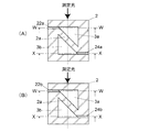
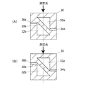
図2及び図3にフローセル2の断面図を示す。図2(A)はフローセルの入口部分、図3(A)及び(B)においてはY−Y位置における横断面図であり、(B)はフローセルの出口口部分、図3(A)及び(B)においてはZ−Z位置における横断面図である。図3(A)はフローセルの参照セル側、図2(A)及び(B)においてはW−W位置における縦断面図であり、(B)はフローセルの試料セル側、図2(A)及び(B)においてはX−X位置における縦断面図である。
2 and 3 are sectional views of the
フローセル2は2つのセル3aと3bを測定光の光軸に対して傾斜した隔壁2aによって仕切っている。この実施例では、隔壁2aは光軸に対して45°傾斜している。セル3aは参照溶液を流通させるための参照セルであり、セル3bは試料溶液を流通させるための試料セルである。両セル3a,3bは同一の直角三角形断面を有し、隔壁2aを軸として対称に配置されている。
The
参照セル3aは測定光に対して垂直な方向から参照溶液を流入させる入口22aと、測定光に対して垂直な方向に参照溶液を流出させる出口22bを備えている。参照セル3aは測定光の光軸に対して垂直な面をもつ。隔壁2aの測定光の光軸に対して垂直な面と隔壁2aとの間の隔壁2aに入口22a及び出口22bが設けられている。
The
試料セル3bは測定光に対して垂直な方向から試料溶液を流入させる入口24aと、測定光に対して垂直な方向に試料溶液を流出させる出口24bを備えている。試料セル3bは測定光の光軸に対して垂直な面をもつ。隔壁2aの測定光の光軸に対して垂直な面と隔壁2aとの間の鋭角部の近傍に入口24a及び出口24bが設けられている。
The
フローセル2の断面は、例えば一辺が5mmの正方形であり、その中央部に例えば一辺が2mmの正方形が2等分された形状の断面をもつ参照セル3aと試料セル3bが配置されている。測定光はスリット8によって参照セル3a及び試料セル3bの中央部を通過するように調整されている。
The cross section of the
参照セル3a及び試料セル3bの入口22a,24a及び出口22b,24bが隔壁2aの測定光に対して垂直な面と隔壁2aとの間の鋭角部の近傍に設けられているので、既述のように、各セルを流れる流体の断面における濃度分布は、図4(B)に示すような状態となる。これにより、図4(A)に示される従来のフローセル濃度分布よりも、測定光が通過する領域における濃度ムラが小さくなり、同一セル内での測定光の屈折量が小さくなる。これにより、受光素子16上に結像されるスリット像の位置のずれが小さくなり、示差屈折率計の検出精度が向上する。
Since the
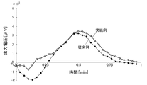
図5は同実施例の示差屈折率計と従来の示差屈折率計とを同じ条件で用いた場合の受光素子からの出力信号の時間変化の計測データの一例を示すグラフである。縦軸は出力信号の強度[μV]であり、横軸は時間[min]である。このグラフでは、同実施例の示差屈折率計の信号波形が実線で示されており、従来の示差屈折率計の信号波形が破線で示されている。 FIG. 5 is a graph showing an example of measurement data of the time change of the output signal from the light receiving element when the differential refractometer of the same embodiment and the conventional differential refractometer are used under the same conditions. The vertical axis represents the output signal intensity [μV], and the horizontal axis represents time [min]. In this graph, the signal waveform of the differential refractometer of the same embodiment is shown by a solid line, and the signal waveform of the conventional differential refractometer is shown by a broken line.
従来の示差屈折率計では、0〜0.25minの時間帯で負のピークが発生している。これは、試料セルの断面形状に起因して発生する試料の濃度ムラによって測定光が屈折され、受光素子16上に結像される測定光の位置が本来の位置からずれたためである。これに対し、実施例の示差屈折率計では、同時間帯の負のピークが小さくなっている。これは、試料セル3b断面における測定光通過領域の濃度ムラが小さくなっていることによって、受光素子16上に結像されるスリット像の位置ずれが小さくなっていることを意味する。
In the conventional differential refractometer, a negative peak occurs in a time zone of 0 to 0.25 min. This is because the measurement light is refracted by the sample density unevenness caused by the cross-sectional shape of the sample cell, and the position of the measurement light imaged on the
2 フローセル
2a 隔壁
3a 参照セル
3b 試料セル
4 光源
6 測定光
8 スリット
10 レンズ
12 ミラー
14 ゼログラス
16 受光素子
20 演算処理装置
22a,24a 流体入口
22b,24b 流体出口
2 flow
Claims (1)
同一の三角形断面をもち測定光の光軸に対して垂直な面をもつ試料セルと参照セルが測定光の光軸に対して傾斜した隔壁によって仕切られているとともに隔壁を軸として対称に配置され、両セルの入口及び出口が前記隔壁の測定光に対して垂直な面と隔壁との間の鋭角部近傍に前記光軸に対して垂直に設けられているフローセルと、
前記フローセルを経た測定光を受光するための受光素子と、
測定光を前記フローセルを透過させてから前記受光素子に導く光学系と、を備えた示差屈折率計。 A light source that emits measurement light;
A sample cell and a reference cell having the same triangular cross section and a plane perpendicular to the optical axis of the measurement light are separated by a partition that is inclined with respect to the optical axis of the measurement light, and are symmetrically arranged with the partition as an axis. A flow cell in which the inlet and outlet of both cells are provided perpendicular to the optical axis in the vicinity of an acute angle portion between the surface perpendicular to the measurement light of the partition and the partition;
A light receiving element for receiving measurement light that has passed through the flow cell;
An optical system that guides measurement light to the light receiving element after passing through the flow cell.
Priority Applications (1)
| Application Number | Priority Date | Filing Date | Title |
|---|---|---|---|
| JP2010210348A JP2012068024A (en) | 2010-09-21 | 2010-09-21 | Differential refractometer |
Applications Claiming Priority (1)
| Application Number | Priority Date | Filing Date | Title |
|---|---|---|---|
| JP2010210348A JP2012068024A (en) | 2010-09-21 | 2010-09-21 | Differential refractometer |
Publications (1)
| Publication Number | Publication Date |
|---|---|
| JP2012068024A true JP2012068024A (en) | 2012-04-05 |
Family
ID=46165487
Family Applications (1)
| Application Number | Title | Priority Date | Filing Date |
|---|---|---|---|
| JP2010210348A Pending JP2012068024A (en) | 2010-09-21 | 2010-09-21 | Differential refractometer |
Country Status (1)
| Country | Link |
|---|---|
| JP (1) | JP2012068024A (en) |
Cited By (1)
| Publication number | Priority date | Publication date | Assignee | Title |
|---|---|---|---|---|
| US10024789B2 (en) | 2014-02-07 | 2018-07-17 | Shimadzu Corporation | Measurement method using differential refractometer, differential refractometer using the measurement method, and liquid chromatograph |
-
2010
- 2010-09-21 JP JP2010210348A patent/JP2012068024A/en active Pending
Cited By (1)
| Publication number | Priority date | Publication date | Assignee | Title |
|---|---|---|---|---|
| US10024789B2 (en) | 2014-02-07 | 2018-07-17 | Shimadzu Corporation | Measurement method using differential refractometer, differential refractometer using the measurement method, and liquid chromatograph |
Similar Documents
| Publication | Publication Date | Title |
|---|---|---|
| TWI651529B (en) | Concentration measuring device | |
| JP4594206B2 (en) | Improved differential refractometer and measurement method for measuring refractive index differential | |
| US9091573B2 (en) | Determining a flow characteristic of an object being movable in an element | |
| JP4786906B2 (en) | High sensitivity differential refractometer flow cell and design method thereof | |
| JP2018025499A (en) | Concentration measuring device | |
| US7724356B2 (en) | Apparatus for measuring differential refractive index | |
| US10025077B2 (en) | Device for measuring solution concentration | |
| JP2012068024A (en) | Differential refractometer | |
| CN105393106B (en) | Device for measuring scattering of a sample | |
| JP2013036807A (en) | Turbidimeter | |
| US11175218B2 (en) | Flow cell and detector equipped with the flow cell | |
| EP2378274B1 (en) | Surface plasmon resonance measuring apparatus | |
| JP4793413B2 (en) | Differential refractive index detector | |
| KR20090129797A (en) | Distance measuring apparatus | |
| JP7226561B2 (en) | Liquid chromatograph detector | |
| WO2017119063A1 (en) | Differential refractive index detector | |
| JP2008051608A (en) | Optical cell for concentration measurement | |
| JP2007155674A (en) | Microcell | |
| JP2010025580A (en) | Optical unit | |
| JP6784105B2 (en) | Absorbance detector with flow cell and its flow cell | |
| CN105527224B (en) | It is a kind of for analyzing the device and method of sample | |
| US20180045642A1 (en) | Gas detection device and method for detecting gas concentration | |
| JP3117245U (en) | Differential refractive index detector | |
| WO2017046913A1 (en) | Differential refractive index detector | |
| JP2007127448A (en) | Analyzing optical device |