JP2012045877A - Inkjet drawing device - Google Patents
Inkjet drawing device Download PDFInfo
- Publication number
- JP2012045877A JP2012045877A JP2010191843A JP2010191843A JP2012045877A JP 2012045877 A JP2012045877 A JP 2012045877A JP 2010191843 A JP2010191843 A JP 2010191843A JP 2010191843 A JP2010191843 A JP 2010191843A JP 2012045877 A JP2012045877 A JP 2012045877A
- Authority
- JP
- Japan
- Prior art keywords
- mirror
- head
- ink
- light source
- source unit
- Prior art date
- Legal status (The legal status is an assumption and is not a legal conclusion. Google has not performed a legal analysis and makes no representation as to the accuracy of the status listed.)
- Withdrawn
Links
Images


Abstract
Description
本発明は、噴射ヘッドに設けられた噴射ノズルから液体を噴射する技術に関する。 The present invention relates to a technique for ejecting liquid from an ejection nozzle provided in an ejection head.
噴射ヘッドを往復動させながら、噴射ヘッドに設けられた噴射ノズルから媒体上に液体を噴射するインクジェット描画装置が知られている。このインクジェット描画装置を利用して、紫外線(紫外光)の照射によって硬化する液体を、噴射ノズルから媒体上に噴射するとともに、噴射した液体に紫外線を照射して液体を硬化させることで、媒体上に液体を定着させる技術が開発されている。
このような技術では、瞬時に液体を硬化させて媒体に定着させることができるので、例えば、プラスチック(ポリエチレンテレフタラート、ポリカーボネート)等、液体を吸収しない素材に対しても液体を良好に定着させることが可能である。そして、このような従来のインクジェット描画装置には、紫外光を発する光源がキャリッジに搭載されているものがある(例えば、特許文献1参照)。
2. Related Art There is known an ink jet drawing apparatus that ejects a liquid onto a medium from an ejection nozzle provided in an ejection head while reciprocating the ejection head. By using this ink jet drawing apparatus, a liquid that is cured by irradiation with ultraviolet rays (ultraviolet light) is ejected from the ejection nozzle onto the medium, and the liquid is cured by irradiating the ejected liquid with ultraviolet rays. A technology for fixing a liquid on the surface has been developed.
In such a technique, the liquid can be instantly cured and fixed on the medium, so that the liquid can be well fixed even on a material that does not absorb liquid, such as plastic (polyethylene terephthalate, polycarbonate). Is possible. Such a conventional ink jet drawing apparatus includes a light source that emits ultraviolet light mounted on a carriage (see, for example, Patent Document 1).
上記特許文献1に記載されたインクジェット描画装置では、1つの光源からの紫外光の経路を、複数の経路のうちの1つの経路に選択的に切り替えることができる。このため、光源の数量を低減しやすくすることができる。この結果、インクジェット描画装置を小型化しやすくすることができる。
しかしながら、上記特許文献1に記載されたインクジェット描画装置では、光源がキャリッジに搭載されているので、キャリッジにかかる負荷が大きくなりやすい。キャリッジにかかる負荷が大きくなると、キャリッジの位置制御にかかる精度、ひいては記録精度を向上させることが困難となる。
つまり、従来のインクジェット描画装置では、描画精度を向上させることが困難であるという課題がある。
In the ink jet drawing apparatus described in Patent Document 1, the path of ultraviolet light from one light source can be selectively switched to one of a plurality of paths. For this reason, it is possible to easily reduce the number of light sources. As a result, the ink jet drawing apparatus can be easily miniaturized.
However, in the ink jet drawing apparatus described in Patent Document 1, since the light source is mounted on the carriage, the load on the carriage tends to increase. When the load applied to the carriage increases, it becomes difficult to improve the accuracy of the carriage position control, and thus the recording accuracy.
That is, the conventional ink jet drawing apparatus has a problem that it is difficult to improve drawing accuracy.
[適用例1]本適用例に記載のインクジェット描画装置は、シート状被記録媒体を支持するプラテンと、前記被記録媒体上に像様に活性光線硬化型インクを液滴として吐出するインクジェットヘッドと、第1のミラーと、第2のミラーと、を有するヘッドキャリッジと、前記ヘッドキャリッジを前記主走査方向に移動させるヘッド移動機構と、活性光線を発する活性光線照射部と、前記活性光線照射部を前記主走査方向に移動させる照射部移動機構と、制御部と、を備え、前記ヘッドキャリッジの主走査方向において、前記インクジェットヘッドが前記第1のミラーと前記第2のミラーとの間に位置するように配置されており、前記第1のミラー又は前記第2のミラーのうち、前記ヘッドキャリッジの移動方向後方に位置するミラーに前記活性光線照射部からの活性光線が照射されて、当該ミラーにより反射された活性光線が前記被記録媒体上の前記活性光線硬化型インクに照射されるように、前記制御部は、前記ヘッド移動機構及び前記照射部移動機構を制御することを特徴とする。 Application Example 1 An ink jet drawing apparatus according to this application example includes a platen that supports a sheet-like recording medium, an ink jet head that ejects actinic ray curable ink as droplets imagewise on the recording medium, and , A head carriage having a first mirror and a second mirror, a head moving mechanism for moving the head carriage in the main scanning direction, an actinic ray irradiating unit for emitting actinic rays, and the actinic ray irradiating unit An irradiating part moving mechanism for moving the ink jet head in the main scanning direction, and a control unit, wherein the ink jet head is positioned between the first mirror and the second mirror in the main scanning direction of the head carriage. Of the first mirror or the second mirror, the active mirror is positioned on a mirror located behind the moving direction of the head carriage. The control unit includes the head moving mechanism and the head moving mechanism so that the active light from the light irradiation unit is irradiated and the active light reflected by the mirror is applied to the active light curable ink on the recording medium. The irradiation unit moving mechanism is controlled.
上記の構成では、ヘッドキャリッジに、第1のミラー及び第2のミラーがインクジェットヘッドともに設けられており、ヘッドキャリッジはヘッド移動機構により移動する。そして、活性光線照射部は、ヘッド移動機構とは異なる照射部移動機構により移動する。そして、制御部のヘッド移動機構及び前記照射部移動機構の制御により、第1のミラー又は第2のミラーのうち、ヘッドキャリッジの移動方向後方に位置するミラーに活性光線照射部からの光が照射されて、このミラーにより反射された光が被記録媒体上の活性光線硬化型インクに照射される。
上記の構成によると、ヘッドキャリッジには活性光線照射部が設けられていないため、ヘッドキャリッジを軽量化することができる。したがって、キャリッジの位置制御にかかる精度、ひいては記録精度を向上させることができる。また、インクジェットヘッドにより被記録媒体上に画像が描画されてから、光源ユニットにより被記録媒体上の画像部に紫外線が照射され、硬化されるまでの時間を短時間にすることができ、被記録媒体上に形成された画像が被記録媒体上でにじんだり、画像がずれたりする事による画像乱れが生じることを防止できる。これにより、高画質な画像を形成することができる。
In the above configuration, the head carriage is provided with the first mirror and the second mirror together with the ink jet head, and the head carriage is moved by the head moving mechanism. Then, the actinic ray irradiation unit moves by an irradiation unit moving mechanism different from the head moving mechanism. Then, by the control of the head moving mechanism of the control unit and the irradiation unit moving mechanism, the light from the actinic ray irradiation unit is irradiated to the mirror located behind the moving direction of the head carriage among the first mirror or the second mirror. Then, the light reflected by the mirror is applied to the actinic ray curable ink on the recording medium.
According to the above configuration, the head carriage is not provided with the actinic ray irradiating unit, so that the head carriage can be reduced in weight. Therefore, it is possible to improve the accuracy of the carriage position control, and thus the recording accuracy. In addition, the time from when an image is drawn on the recording medium by the inkjet head to when the image portion on the recording medium is irradiated with ultraviolet rays by the light source unit and cured can be shortened, and the recording It is possible to prevent image disturbance caused by the image formed on the medium blurring on the recording medium or the image shifting. Thereby, a high-quality image can be formed.
[適用例2]上記適用例に記載のインクジェット描画装置であって、前記第1のミラー又は前記第2のミラーは、前記インクジェットヘッドのノズル面よりも高い位置に配置されてもよい。 Application Example 2 In the ink jet drawing apparatus according to the application example described above, the first mirror or the second mirror may be disposed at a position higher than a nozzle surface of the ink jet head.
このような構成によれば、被記録媒体とインクジェットヘッドとの間に、活性光線照射部からの光が入り込むのを抑制できる。これにより、被記録媒体上に吐出不良による画像乱れが防止された高画質な画像を形成することができる。また、インクジェットヘッドに洗浄/清掃等のメンテナンスを施すことなく、長時間安定してインク液滴を良好に吐出させることができる。 According to such a structure, it can suppress that the light from an actinic ray irradiation part enters between a recording medium and an inkjet head. As a result, it is possible to form a high-quality image in which image disturbance due to ejection failure is prevented on the recording medium. In addition, ink droplets can be ejected satisfactorily for a long time without performing maintenance such as cleaning / cleaning on the inkjet head.
[適用例3]上記適用例に記載のインクジェット描画装置であって、前記活性光線照射部は、前記インクジェットヘッドのノズル面よりも高い位置に配置されてもよい。 Application Example 3 In the ink jet drawing apparatus according to the application example, the actinic ray irradiation unit may be arranged at a position higher than a nozzle surface of the ink jet head.
このような構成によれば、被記録媒体とインクジェットヘッドとの間に、活性光線照射部からの光が入り込むのを抑制できる。これにより、吐出不良による画像乱れが防止された高画質な画像を被記録媒体上に形成することができる。また、インクジェットヘッドに洗浄/清掃等のメンテナンスを施すことなく、長時間安定してインク液滴を良好に吐出させることができる。 According to such a structure, it can suppress that the light from an actinic ray irradiation part enters between a recording medium and an inkjet head. As a result, it is possible to form a high-quality image on the recording medium in which image disturbance due to ejection failure is prevented. In addition, ink droplets can be ejected satisfactorily for a long time without performing maintenance such as cleaning / cleaning on the inkjet head.
以下、本発明に係るインクジェット描画装置の好適な実施形態について、添付図面を参照して詳細に説明する。 DESCRIPTION OF EXEMPLARY EMBODIMENTS Hereinafter, preferred embodiments of an ink jet drawing apparatus according to the invention will be described in detail with reference to the accompanying drawings.
図1は、本発明に係るインクジェット描画装置を適用する一実施形態としての、製版装置の概略構成を示す模式的上面図であり、図2は、図1に示す製版装置の模式的な側面図である。また、図3は、図1に示すインクジェットヘッドの一例の概略構成を示す断面図であり、図4は、図1に示す製版装置の走査型UV照射部を背面から見た模式的な断面図である。 FIG. 1 is a schematic top view showing a schematic configuration of a plate making apparatus as an embodiment to which an ink jet drawing apparatus according to the present invention is applied, and FIG. 2 is a schematic side view of the plate making apparatus shown in FIG. It is. 3 is a cross-sectional view showing a schematic configuration of an example of the ink jet head shown in FIG. 1, and FIG. 4 is a schematic cross-sectional view of the scanning UV irradiation unit of the plate making apparatus shown in FIG. It is.
以下においては、被記録媒体として平版印刷原版、活性光線硬化型インクとして紫外線硬化型インク(以下、UVインクという)Q、紫外線(以下、UV光という)を照射するための点状または略点状の光源として紫外線ランプ(以下、UVランプという)を用いて印刷版を作製する製版装置を代表例として説明する。しかし、本発明はこれに限定されるものではなく、例えば、プリント基板を作製するプリント基板作製装置、紙、樹脂シート等に画像を描画するインクジェットプリンターなどであっても良い。 In the following, a lithographic printing original plate as a recording medium, an ultraviolet ray curable ink (hereinafter referred to as UV ink) Q as an actinic ray curable ink, and a dot shape or a substantially dot shape for irradiating ultraviolet rays (hereinafter referred to as UV light). A plate making apparatus for producing a printing plate using an ultraviolet lamp (hereinafter referred to as a UV lamp) as a light source will be described as a representative example. However, the present invention is not limited to this, and may be, for example, a printed circuit board manufacturing apparatus for manufacturing a printed circuit board, an ink jet printer for drawing an image on paper, a resin sheet, or the like.
図1および図2に示す製版装置10は、被記録媒体としてのシート状の印刷原版Pの記録面にインクジェット記録方法により印刷インキ受容性(親インク性)の画像部を形成するインクジェット描画装置を適用するものである。
製版装置10は、印刷原版Pを支持するプラテン12と、印刷原版Pに像様にUVインクQを吐出するインクジェットヘッド(記録ヘッド)62及び第1のミラー47A並びに第2のミラー47Bを備えるヘッドキャリッジ14と、印刷原版Pに吐出されたUVインクQにUV光を主走査方向(図1中矢印Yで示す方向)に走査して照射する走査型UV照射部16と、ヘッドキャリッジ14を主走査方向であるY方向に移動させるヘッド移動機構18と、プラテン12に支持された印刷原版Pを主走査方向(Y方向)と略直交する副走査方向(図1および図2中矢印Xで示す方向)に搬送する搬送機構20と、ヘッドキャリッジ14、走査型UV照射部16、ヘッド移動機構18および搬送機構20の動作を制御する制御部22と、を有する。
A
The
プラテン12は平板形状を有し、図示しない自動給版装置から供給された印刷原版Pをその表面に支持するものである。ここで、プラテン12の表面には、空気吸引孔を設けてヘッドキャリッジ14による描画中、つまりヘッドキャリッジ14のインクジェットヘッド62による描画中に印刷原版Pを吸着することが好ましい。これにより、印刷原版Pの平面性を適正に維持できる。また、搬送機構20によって印刷原版Pを副走査方向(X方向)に搬送する際には、プラテン12の表面は、印刷原版Pの裏面との摩擦係数が小さいものであるのが好ましい。なお、プラテン12は、図示しない製版装置筐体に取り付けられる。
The
搬送機構20は、ヘッドキャリッジ14に対して印刷原版Pを副走査(X)方向に搬送するものである。搬送機構20は、図示しない駆動源と接続する駆動ローラーである送りローラー30と、従動ローラーである抑えローラー32とを有しており、送りローラー30と抑えローラー32との間に印刷原版Pを挟持して副走査(X)方向に搬送する。送りローラー30と抑えローラー32とは、印刷原版Pの搬送経路上において、印刷原版Pの表裏を上下から挟む様に配置されている。自動給版装置から供給された印刷原版Pは、送りローラー30と抑えローラー32との間に所定のニップ圧で挟持される。送りローラー30を図示しない駆動源によって所定方向(図2において反時計回り)に回転させることで、印刷原版Pは副走査(X)方向に搬送される。
The
また、ヘッドキャリッジ14による描画中に、印刷原版Pをプラテン12の表面に吸着させる場合には、送りローラー30と抑えローラー32とは回転を停止し、ヘッドキャリッジ14による非描画中に、送りローラー30が図示しない駆動源によって回転駆動され、抑えローラー32との間に挟持している印刷原版Pを副走査(X)方向に搬送するように構成するのが好ましい。すなわち、搬送機構20は、印刷原版Pを間欠的に副走査方向へ搬送するのが好ましい。なお、送りローラー30および抑えローラー32は、共に、図示しない製版装置筐体に回転可能に支持される。
なお、本発明に用いられる搬送機構(上記実施形態では、搬送機構20として説明した。)は、印刷原版を副走査方向に搬送できるものであればどのような形式のものでも良く、公知の全ての副走査搬送機構が適用可能である。
Further, when the printing original plate P is attracted to the surface of the
The transport mechanism used in the present invention (described in the above embodiment as the transport mechanism 20) may be of any type as long as it can transport the printing original plate in the sub-scanning direction. The sub-scanning transport mechanism can be applied.
ヘッドキャリッジ14は、インクジェットヘッド62と、第1のミラー47Aと、第2のミラー47Bと、を有する。本実施形態では、ヘッドキャリッジ14は、プラテン12とインクジェットヘッド62が対向して配置され、プラテン12表面に支持された印刷原版Pの記録面の鉛直方向上方にヘッドキャリッジ14が配置される。ヘッドキャリッジ14は、後述するヘッド移動機構18により、プラテン12の表面と平行に、主走査方向(Y方向)に往復移動(走査)可能な状態で支持されている。
The
ヘッドキャリッジ14のインクジェットヘッド62は、プラテン12上に載置された印刷原版Pの記録面上に、像様にUVインクQをインク液滴として吐出する。すなわち、記録されるべき画像の画像データに基づく吐出信号に応じてUVインクQを吐出する。吐出されたUVインクQにより印刷原版P上に画像を記録し、親インキ性の画像部を形成するものである。
ここで、吐出信号とは、記録されるべき画像の画像データに基づいて、画像部となる部分に選択的にインクを塗布するように液滴を吐出させるためのデータ信号である。なお、印刷原版Pの記録面は、撥インキ性(親水性)を呈し、UVインクQの吐出によって形成された画像部のみが親インキ性(疎水性)を呈する。
The
Here, the ejection signal is a data signal for ejecting droplets so as to selectively apply ink to a portion to be an image portion based on image data of an image to be recorded. The recording surface of the printing original plate P exhibits ink repellency (hydrophilicity), and only the image portion formed by the ejection of the UV ink Q exhibits ink affinity (hydrophobicity).
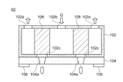
図3は、図1に示す製版装置10に用いられたヘッドキャリッジ14のインクジェットヘッド62の概略構成を示す断面図である。
インクジェットヘッド62は、ケース102と、ノズルプレート104と、ガードプレート106と、圧電素子108を有する。
FIG. 3 is a cross-sectional view showing a schematic configuration of the
The
図3に示したインクジェットヘッド62は、ケース102に形成された吐出口102cとノズルプレート104に形成されたノズル104aとによりUVインクQの流路が形成されている。インク流路の側面に相当する位置のノズルプレート104には複数のノズル104aが連通して形成され、ケース102内のインクQをインク流路の側面のノズル104aからインク液滴として吐出する、いわゆるサイドシューター(side shooter)型のインクジェットヘッドである。
ここで、図3には、インクジェットヘッド62の一部のノズル104aのみを示したが、インクジェットヘッド62は、インク液滴を吐出する図示しない複数のノズル104aを有しており、これらノズル104aは、描画時の副走査方向(X方向)に一列に配置されている。
In the
Here, FIG. 3 shows only some of the
以下、インクジェットヘッド62の各部材について詳細に説明する。
ケース102は、中空の箱型形状であり、1つの面に複数のインク出口102aと、複数のインク入口102bとが形成されている。これらインク出口102a及びインク入口102bが形成された面に対向する面において、インク出口102aとインク入口102bとの間となる位置にそれぞれ吐出口102cが形成されている。また、ケース102内部の圧力室でもあるインク流路には各吐出口102cに対応してピエゾ型(例えばPZT駆動など)の圧電素子108が配置されている。
Hereinafter, each member of the
The
ノズルプレート104は、ケース102の吐出口102c側の面に配置され、吐出口102cに対応する位置にノズル104aが形成されている。ノズル104aは、吐出口102cと連通しており、吐出口102cに送給されたインクQがインク液滴として吐出される。
The
ガードプレート106は、ノズルプレート104の外面に配置され、ノズルプレート104のノズル104aの近くに突出して配置されている。ガードプレート106は、ノズル104aに他の部材が衝突しないようにノズル104aを保護する。
The
インクジェットヘッド62は、圧電素子108を駆動させてインク入口102bから吐出口102cへ送給されたインクQをノズル104aから吐出させる。そして、吐出されないインクQがインク出口102aから送出される。このとき、ケース102の圧力室内においてインクQが循環及び攪拌されることで沈殿することなくインクQがインク液滴として吐出される。インクジェットヘッド62には、ヒーター等でヘッド全体を調温加熱してインクQの粘度を低減させて吐出しやすくする方法を用いてもよい。
The
なお、インクジェットヘッドは、上記実施形態のサイドシューター型のピエゾ方式に限定されず、コンティニュアス型およびオンデマンド型のピエゾ方式、サーマル方式、ソリッド方式、静電吸引方式等の種々の方式のインクジェットヘッド(吐出ヘッド)を用いることができ、特に、オンデマンド型の種々の方式のインクジェットヘッドを用いることが好ましい。また、ノズルは、単列配置に限定されず、複数列としても千鳥格子状の配置としてもよい。 The ink jet head is not limited to the side shooter type piezo method of the above-described embodiment, and various types of ink jets such as a continuous type and an on-demand type piezo method, a thermal method, a solid method, and an electrostatic suction method. A head (discharge head) can be used, and it is particularly preferable to use various types of on-demand ink jet heads. Further, the nozzles are not limited to a single row arrangement, and may be arranged in a plurality of rows or in a staggered pattern.
ヘッドキャリッジ14の第1のミラー47A及び第2のミラー47Bは、図11のように、後述する光源ユニット(紫外線照射部)38からのUV光を反射して、印刷原版Pの記録面上に吐出されたUVインクQに照射する。
The
印刷原版Pの記録面を鉛直方向の上側から見た場合、インクジェットヘッド62は、主走査方向(Y方向)において、第1のミラー47A及び第2のミラー47Bとの間に位置するように配置される。第1のミラー47A及び第2のミラー47Bの照射範囲は、副走査方向(X方向)に配置された複数のノズル104aの列の長さよりも長い照射範囲となるように構成される。
When the recording surface of the printing original plate P is viewed from above in the vertical direction, the
典型的には、第1のミラー47A及び第2のミラー47Bの副走査方向(X方向)の長さは、上記の複数のノズル104aの列の長さより長く構成されている。そして、主走査方向(Y方向)においてインクジェットヘッド62を挟む両側に配置された第1のミラー47A或いは第2のミラー47Bにより、光源ユニット38からのUV光を反射させるため、インクジェットヘッド62が主走査方向(Y方向)に印刷原版Pの上を1回通過する期間においてインクジェットヘッド62から吐出されたUVインクQは、その期間内に光源ユニット38からのUV光が照射されることになる。
Typically, the length of the
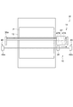
第1のミラー47A及び第2のミラー47Bは、インクジェットヘッド62、特にノズルプレート104よりも鉛直方向において高い位置に配置することが好ましい。図2及び図11のように、第1のミラー47A及び第2のミラー47Bの下端から印刷原版Pの記録面までの高さh1,h2は、ノズルプレート104の鉛直方向における高さh0よりも高くなっている。
The first mirror 47 </ b> A and the second mirror 47 </ b> B are preferably arranged at a position higher in the vertical direction than the
このような構成によれば、印刷原版Pの記録面とインクジェットヘッド62との間に、光源ユニット(紫外線照射部)38からのUV光が入り込むのを抑制できる。これにより、吐出不良による画像乱れが防止された高画質な画像を被記録媒体上に形成することができる。また、インクジェットヘッド62に洗浄/清掃等のメンテナンスを施すことなく、長時間安定してインク液滴を良好に吐出させることができる。
According to such a configuration, it is possible to prevent UV light from the light source unit (ultraviolet irradiation unit) 38 from entering between the recording surface of the printing original plate P and the
図1及び図2に示すように、ヘッド移動機構18は、ヘッドキャリッジ14を主走査方向に往復移動(走査)させるものである。ヘッド移動機構18は、ドライブスクリュー34と、ガイドレール35と、駆動支持部36aと、支持部36bとを有する。ドライブスクリュー34およびガイドレール35は、共に、主走査方向(図1中Y方向)に延伸し、描画可能な最大サイズの印刷原版Pが、主走査方向の一端から他端までを跨ぐように設置されている。
As shown in FIGS. 1 and 2, the
ドライブスクリュー34は、ヘッドキャリッジ14に形成された雌ねじ部(図示せず)と螺合する雄ねじ部を持つボールねじ(図示せず)等からなり、回転することによりヘッドキャリッジ14を主走査方向に移動させる。
ガイドレール35は、ヘッドキャリッジ14に形成された貫通孔に挿通され、ドライブスクリュー34の回転により移動するインクジェットヘッド62の姿勢が変わらないように案内するガイドである。
The
The
また、駆動支持部36aは、ドライブスクリュー34およびガイドレール35の一方の端部に、支持部36bは、それらの他方の端部に設けられ、ドライブスクリュー34を正逆回転可能な状態で支持し、ガイドレール35を移動しないように支持している。駆動支持部36aは、ドライブスクリュー34を駆動するモーター等の駆動源(図示せず)を備える。
The
ヘッドキャリッジ14は、ドライブスクリュー34およびガイドレール35によって移動可能に支持されており、駆動支持部36aによりドライブスクリュー34を正逆回転させることで、ガイドレール35に案内されつつ、Y方向(主走査方向)に往復移動(走査)される。
なお、ヘッド移動機構18は、ヘッドキャリッジ14の姿勢を保つために、複数のガイドレールを備えていても良いし、その他の姿勢保持手段を有していても良い。なお、ヘッドキャリッジ14は、ガイドレール35により、インク液滴を吐出させる部分、つまり、インクジェットヘッド62のインク液滴吐出面がプラテン12と対向した所定の姿勢を維持して移動される。
The
The
ここで、ヘッドキャリッジ14の移動機構としては、上記のヘッド移動機構18に限定されず、種々の公知の移動機構を用いることができる。
例えば、ドライブスクリューをガイドレールなどの棒状部材とし、インクジェットヘッドのY方向の端部の両側にそれぞれガイドワイヤーをつけた構成として、移動方向のガイドワイヤーを巻き取り、ガイドレールに沿って移動させる構成も用いることができる。
またガイドワイヤーの代りにタイミングベルトで移動させても良い。この場合には、ワイヤーリールに代えてタイミングベルト用スプロケットを用いればよい。
また、ラックアンドピニオン機構を用いても良い。また、自走式としても良い。さらに、リニアモーターを用いてもよい。
Here, the moving mechanism of the
For example, the drive screw is a rod-shaped member such as a guide rail, and guide wires are attached to both sides of the Y-direction end of the inkjet head, and the guide wire in the moving direction is wound and moved along the guide rail. Can also be used.
Moreover, you may move with a timing belt instead of a guide wire. In this case, a timing belt sprocket may be used instead of the wire reel.
Further, a rack and pinion mechanism may be used. Moreover, it is good also as a self-propelled type. Further, a linear motor may be used.
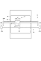
図4は、図1に示す製版装置10の走査型UV照射部16を模式的に示す背面断面図であり、印刷原版Pの送り方向(副走査(X)方向)上流側から下流側を見た図である。
FIG. 4 is a rear cross-sectional view schematically showing the scanning
次に、図4に示すように、走査型UV照射部16は、光源ユニット(紫外線照射部)38および光源ユニット移動機構46を有している。走査型UV照射部16は、ヘッドキャリッジ14に対して印刷原版Pの送り方向(副走査(X)方向)下流側に配置される。
走査型UV照射部16は、光源ユニット38を主走査(Y)方向に走査しながら、ヘッドキャリッジ14に設けられた第1のミラー47Aあるいは第2のミラー47Bのいずれかに向けてUV光を照射する。光源ユニット38から照射されたUV光は、ヘッドキャリッジ14に設けられた第1のミラー47Aあるいは第2のミラー47Bのいずれかにより反射され、印刷原版Pの記録面上のUVインクQに照射される。このUVインクQは、印刷原版Pの記録面上に像様にインクジェットヘッド62から吐出され、画像部を形成したものである。
Next, as shown in FIG. 4, the scanning
The scanning
印刷原版Pの記録面上のUVインクQは、光源ユニット38から照射され反射されたUV光により硬化する。
ここで、走査型UV照射部16は、第1のミラー47Aあるいは第2のミラー47Bのうち、インクジェットヘッド62の主走査方向(Y方向)における移動方向の後方側に位置するミラーに、光源ユニット38からのUV光が照射されるように制御部22により制御される。したがって、インクジェットヘッド62から吐出された直後のUVインクQに対し、光源ユニット38からのUV光が照射されることになる。また、光源ユニット38が、ヘッドキャリッジ14とは独立して移動(走査)することが可能な走査型UV照射部16に設けられるため、ヘッドキャリッジ14に光源ユニット38を取り付ける場合に比して、ヘッドキャリッジ14を軽量化することができる。
The UV ink Q on the recording surface of the printing original plate P is cured by the UV light irradiated and reflected from the
Here, the scanning
図2および図4に示すように、光源ユニット38は、UV光を射出するUVランプ40と、射出されたUV光を、プラテン12上に支持された印刷原版Pの記録面に並行する光とするリフレクター42と、を有する。
光源ユニット38は、筐体51の中に収納されてランプハウスとして構成されている。ここで、筐体51の内面は、鏡面とするのが好ましい。
As shown in FIGS. 2 and 4, the
The
UVランプ40は、UVインクQを硬化させるためのUV光を発する。UVランプ40としては、例えば、超高圧水銀ランプやメタルハライドランプなどの種々のランプ(点状光源)、紫外線蛍光管などのチューブバルブやこれらを用いて略点状にしたランプなどを用いることができる。
これらの光源は、可視光線を含む光を照射してもよい。活性光線硬化型インク(本実施形態では、UVインク)の感光域が可視光域にも感度を持つ場合には、可視光線も含む光を照射することで、より感度を高くすることができ、UVインクの硬化を好適に行うことができる。
なお、本発明においては、本実施形態で用いたUVランプ40の代わりに、UVLEDやUVLEDアレイを用いてもよい。また、UVランプ40としては、ビデオプロジェクターやリアプロジェクション型テレビに用いられている超高圧水銀灯(超高圧水銀ランプ)を用いることが好ましい。UVランプ40として、超高圧水銀灯を用いることで、光源ユニット38を安価にすることができる。
The
These light sources may emit light including visible light. If the photosensitive area of the actinic ray curable ink (in this embodiment, the UV ink) has sensitivity in the visible light range, the sensitivity can be further increased by irradiating light including visible light, The UV ink can be suitably cured.
In the present invention, a UVLED or a UVLED array may be used instead of the
リフレクター42は、UVランプ40を内蔵し、UVランプ40から射出されたUV光を射出する矩形断面形状の射出口42aを備えている。リフレクター42の内面は、鏡面とされており、UVランプ40から射出されたUV光が、内面で吸収されることなく反射される。これにより、UVランプ40から射出されたUV光は、直接またはリフレクター42に反射して、吸収されることなく、射出口42aからUV光として射出される。
The
光源ユニット移動機構46は、図4に示すように、プラテン12、または描画可能な最大サイズの印刷原版Pの搬送経路となる領域の両外側、すなわち主走査方向(Y方向)の両外側に位置する2つのワイヤーリール48aおよびワイヤーリール48bと、これらの2つのワイヤーリール48a,48bに張架されるワイヤー50と、ワイヤーリール48aを回転駆動する駆動源(モーター)52とを有する。ワイヤー50には、光源ユニット38が筐体51の照明窓53を印刷原版Pの送り方向(副走査(X)方向)上流側に向けて固定的に取り付けられている。換言すれば、ワイヤー50には、光源ユニット38が筐体51の照明窓53をヘッドキャリッジ14に向けて固定的に取り付けられている。ワイヤー50の両端部はそれぞれワイヤーリール48a,48bに巻き付けられている。
As shown in FIG. 4, the light source
ワイヤーリール48a,48bは、図示しないフレームに軸支されており、ワイヤーリール48bは、ワイヤー50を巻き取る方向に常に所定の張力で付勢されている。ワイヤーリール48bの付勢方法は、従来公知の技術を利用すればよく、例えば付勢手段として、ぜんまいバネやコイルバネや板状コイルバネを用いることができる。ワイヤーリール48bの付勢力は、ワイヤー50を弛ませることなく光源ユニット38を印刷原版Pから一定の距離に保持できるように設定すればよい。
The
ここで、光源ユニット38、特に、UVランプ40あるいは照明窓53の位置は、インクジェットヘッド62、特にノズルプレート104よりも高い位置に配置することが好ましい。図2のように、照明窓53の下端部から印刷原版Pの記録面までの高さh3は、ノズルプレート104の鉛直方向における高さh0よりも高くなっている。
Here, the position of the
このような構成によれば、印刷原版Pの記録面とインクジェットヘッド62との間に、光源ユニット(紫外線照射部)38からのUV光が入り込むのを抑制できる。これにより、吐出不良による画像乱れが防止された高画質な画像を印刷原版P(被記録媒体)上に形成することができる。
また、インクジェットヘッドに洗浄/清掃等のメンテナンスを施すことなく、長時間安定してインク液滴を良好に吐出させることができる。
According to such a configuration, it is possible to prevent UV light from the light source unit (ultraviolet irradiation unit) 38 from entering between the recording surface of the printing original plate P and the
In addition, ink droplets can be ejected satisfactorily for a long time without performing maintenance such as cleaning / cleaning on the inkjet head.
駆動源52によって、ワイヤー50を巻き出す方向(図4では反時計回り)にワイヤーリール48aを回転駆動すると、ワイヤーリール48bはその付勢力によって回転し、ワイヤー50を巻き取る。ワイヤーリール48aが停止すると、ワイヤー50が所定の張力となったところでワイヤーリール48bも停止する。
逆に、駆動源52がワイヤー50を巻き取る方向(図4では時計回り)にワイヤーリール48aを回転駆動すると、ワイヤーリール48bの付勢力が負けてワイヤー50がワイヤーリール48bから巻き出され、ワイヤーリール48aに巻き取られる。
When the
Conversely, when the
このようにして、走査型UV照射部16は、駆動源52によるワイヤーリール48aの回転駆動によって、ワイヤー50に常にほぼ一定の張力を維持した状態でワイヤー50を主走査方向(図中、矢印Y方向)に往復移動させ、ワイヤー50に取り付けられた光源ユニット38を印刷原版Pの記録面にほぼ平行に、主走査方向に往復移動させる。
In this way, the scanning
なお、図4に示す例では、光源ユニット移動機構46の構成を明瞭に示すために、光源ユニット38がワイヤー50に取り付けられている様子のみを示してあるが、光源ユニット移動機構46は、光源ユニット38の姿勢をプラテン12に対して平行に保つために、光源ユニット38の主走査方向の移動を案内する1以上のガイドレールやその他の姿勢保持手段を備えるのが好ましい。
In the example shown in FIG. 4, only the state in which the
光源ユニット38は、主走査方向に移動することにより、UVランプから射出され、リフレクター42により反射されたUV光を、ヘッドキャリッジ14に照射しながら走査する。制御部22によって、駆動源52によるワイヤーリール48aの回転量を制御し、光源ユニット38の移動を制御することにより、光源ユニット38の往復動に伴って、印刷原版Pの全幅の領域において、左端から右端へ、次いで右端から左端へと、順にUV照射が行われる。
The
ここで、光源ユニット移動機構46は、ヘッド移動機構18よりも機械精度が低くてもよい。これは、光源ユニット38からのUV光が第1のミラー47Aあるいは第2のミラー47Bに到達するように構成すればよいからである。第1のミラー47A及び第2のミラー47Bの主走査方向における長さは、主走査方向における照明窓53の長さより長く構成することが好ましい。
例えば、第1のミラー47A及び第2のミラー47Bの主走査方向における長さが照明窓53の3倍であれば、光源ユニット38のヘッドキャリッジ14に対する移動の遅れが照明窓53の3倍以内に収まるように、光源ユニット移動機構46を制御すればよい。
Here, the mechanical accuracy of the light source
For example, if the length of the
駆動源52は、ワイヤーリール48aを正方向および逆方向に回転させることができるものであればよい。例えば、電動モーターを用いることができる。
The
制御部22は、上述したように、ヘッドキャリッジ14、走査型UV照射部16、ヘッド移動機構18および搬送機構20の動作を制御する。
具体的には、制御部22は、印刷原版Pに画像部を形成するための、ヘッドキャリッジ14のインクジェットヘッドによる画像データに応じたUVインクQの吐出動作、印刷原版Pに画像部を形成しているUVインクQを硬化させるための、走査型UV照射部16によるUV光の走査照射、すなわち光源ユニット移動機構46による光源ユニット38の往復移動(主走査方向)、ヘッド移動機構18によるヘッドキャリッジ14の往復移動(主走査方向)および搬送機構20による印刷原版Pの副走査方向への連続搬送(好ましくは、間欠搬送)を制御する。なお、制御部22は、この他、製版装置10全体、もしくは、図示しない全ての構成要素を制御するものであるのが好ましい。
As described above, the
Specifically, the
ここで、制御部22は、ヘッド移動機構18及び光源ユニット移動機構46により、ヘッドキャリッジ14と光源ユニット38とを主走査方向に、同一周期でかつヘッドキャリッジ14と光源ユニット38との位置関係が所定の範囲内になるように移動させる。
Here, the
次に、図1、2に示す製版装置10の動作を、図5乃至図11を用いて説明する。
図5乃至図10は、図1に示す製版装置10のインクジェットヘッド14と光源ユニット38の位置関係を示す概略上面図である。図11(a)(b)は、インクジェットヘッド14と光源ユニット38の位置関係を示す概略断面図である。
また、文中において左右を用いて説明しているが、左側とは主走査方向(Y方向)において、中央部よりワイヤーリール48a側に向いた方向を指し、右側とは主走査方向(Y方向)において、中央部よりワイヤーリール48b側に向いた方向を指す。
Next, the operation of the
5 to 10 are schematic top views showing the positional relationship between the
In the description, left and right are used, but the left side indicates the direction from the center to the
図1、2に示す製版装置10において、図示しない自動給版装置からプラテン12に印刷原版Pが供給される。プラテン12に供給された印刷原版Pは、搬送機構20により副走査方向(図1中X方向)に所定速度で間欠搬送される。
In the
印刷原版Pは、搬送機構20によりヘッドキャリッジ14と対向する位置まで搬送される。ヘッドキャリッジ14は、ヘッド移動機構18により主走査方向に移動されつつ、画像信号に応じてインクジェットヘッド62からUVインクQを印刷原版Pの表面に吐出させる。これにより、印刷原版Pの表面には、UVインクQにより画像部が形成される。
The printing original plate P is transported to a position facing the
図5に示すように、主走査方向(Y方向)において右側に向かってヘッドキャリッジ14を走査しながらUVインクQを吐出する際には、光源ユニット38からのUV光が第2のミラー47Bに向かう位置関係を保ちながら、ヘッド移動機構18及び光源ユニット移動機構46により、ヘッドキャリッジ14と光源ユニット38とを主走査方向において移動させる。
As shown in FIG. 5, when the UV ink Q is ejected while scanning the
ここで、図11(b)に示すように、光源ユニット38からのUV光が第2のミラー47Bに向かうように、ヘッドキャリッジ14と光源ユニット38との相対的な位置関係が設定される。ここで、記録面に対して並行して出射された光源ユニット38からのUV光は、第2のミラー47Bに照射される。そして、第2のミラー47Bに照射されたUV光は、第2のミラー47Bにより反射されることで、印刷原版Pの記録面に向けて導かれる。印刷原版Pの記録面には、インクジェットヘッド62から吐出されたUVインクQが配置されているため、光源ユニット38からのUV光は、このUVインクQに照射されて、UVインクQは硬化することになる。
Here, as shown in FIG. 11B, the relative positional relationship between the
そして、図6に示すように、ヘッドキャリッジ14、特にインクジェットヘッド62が印刷原版Pと対向する位置を通過して、プラテン12の右側に位置すると、ヘッドキャリッジ14は停止する。一方、光源ユニット38は、停止せず、主走査方向を右側に移動する。また、この主走査方向の移動が終了した後、プラテン12に供給された印刷原版Pは、搬送機構20により副走査方向(図1中X方向)に所定量搬送される。
As shown in FIG. 6, when the
そして、図7に示すように、光源ユニット38からのUV光が第2のミラー47Bに向かう状態から第1のミラー47Aに向かう状態になるまで主走査方向を右側に移動して、光源ユニット38は停止する。
Then, as shown in FIG. 7, the main scanning direction is moved to the right until the UV light from the
次に、図8に示すように、主走査方向(Y方向)において左側に向かってヘッドキャリッジ14を走査しながらUVインクQを吐出する際には、光源ユニット38からのUV光が第1のミラー47Aに向かう位置関係を保ちながら、ヘッド移動機構18及び光源ユニット移動機構46により、ヘッドキャリッジ14と光源ユニット38とを主走査方向を左側に移動させる。
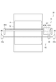
ここで、図11(a)に示すように、光源ユニット38からのUV光が第1のミラー47Aに向かうように、ヘッドキャリッジ14と光源ユニット38との相対的な位置関係が設定されている。ここで、記録面に対して並行して出射された光源ユニット38からのUV光は、第1のミラー47Aに照射される。そして、第1のミラー47Aに照射されたUV光は、第1のミラー47Aにより反射されることにより、印刷原版Pの記録面に向けて導かれる。印刷原版Pの記録面には、インクジェットヘッド62から吐出されたUVインクQが配置されているため、光源ユニット38からのUV光は、このUVインクQに照射されて、UVインクQは硬化することになる。
Next, as shown in FIG. 8, when the UV ink Q is ejected while scanning the
Here, as shown in FIG. 11A, the relative positional relationship between the
そして、図9に示すように、ヘッドキャリッジ14、特にインクジェットヘッド62が印刷原版Pと対向する位置を通過して、プラテン12の左側に位置すると、ヘッドキャリッジ14は停止する。一方、光源ユニット38は、停止せず、主走査方向を左側に移動する。また、この主走査方向の移動が終了した後、プラテン12に供給された印刷原版Pは、搬送機構20により副走査方向(図1中X方向)に所定量搬送される。
そして、図10に示すように、光源ユニット38からのUV光が第1のミラー47Aに向かう状態から第2のミラー47Bに向かう状態になるまで移動して、光源ユニット38は停止する。次に、画像の形成が終わっていなければ図5に戻りインクジェットヘッド62による描画と光源ユニット38によるUV光照射が行われることになる。
As shown in FIG. 9, when the
Then, as shown in FIG. 10, the UV light from the
このように、光源ユニット38の移動期間は、ヘッドキャリッジ14の移動期間より若干長い。また、光源ユニット38の移動距離は、ヘッドキャリッジ14の移動距離より若干長い。なお、この移動期間の差を利用して、搬送機構20による印刷原版Pの副走査方向の搬送やインクジェットヘッドの定期フラッシングを行ってもよい。
Thus, the movement period of the
そして、搬送機構20による印刷原版Pの副走査方向の搬送と、ヘッド移動機構18によるヘッドキャリッジ14の主走査方向(図1中Y方向)の往復移動により、ヘッドキャリッジ14のインクジェットヘッド62は、印刷原版Pの全面を走査し、印刷原版Pの全面における所要の位置にUVインクQによる画像部を形成する。
より具体的には、図1に示すように、インクジェットヘッドキャリッジ14が主走査方向の印刷原版P(被記録媒体)の全域を走査する毎に、搬送機構20が印刷原版Pを副走査方向にdx移動させることで、印刷原版P全域を走査させ、画像を形成させる。
Then, the
More specifically, as shown in FIG. 1, every time the
このように、ヘッドキャリッジ14の移動は、光源ユニット38に対して平面視で互いに重ならない位置で行われる。よって、ヘッドキャリッジ14と光源ユニット38との相対的な位置関係の調整は、互いに干渉することなく行われるため、制御が容易となる。また、光源ユニット38及び第1のミラー47A、第2のミラー47Bを印刷原版Pに対して近接して配置できるため、特許文献1のように、光源をインクジェットヘッド62の上に配置する構成に比して、光源ユニット38から印刷原版Pの印刷面までの光路を短くすることができる。よって、光源ユニット38からのUV光をロスなく、印刷原版P上のUVインクQに照射することができる。
In this way, the
また、第1のミラー47A又は第2のミラー47Bのうち、インクジェットヘッド62に対してヘッドキャリッジ14の進行方向後ろ側のミラーに対し、光源ユニット38からのUV光が照射される。そして、ヘッドキャリッジ14のインクジェットヘッド62に対向した位置を通過した印刷原版P(その部分)は、その後、第1のミラー47A又は第2のミラー47Bのうち、インクジェットヘッド62に対してヘッドキャリッジ14の進行方向後ろ側のミラーに対向した位置に搬送される。したがって、インクジェットヘッド62から吐出されたUVインクQには、このUVインクQを吐出した主走査方向の移動期間中に、光源ユニット38からのUV光が照射されることになる。よって、インクジェットヘッド62により印刷原版P上に画像が描画されてから、光源ユニットにより印刷原版P上の画像部にUV光が照射され、硬化されるまでの時間を短時間にすることができ、印刷原版P上に形成された画像が印刷原版P上ににじんだり、画像がずれたりする事による画像乱れが生じることを防止できる。これにより、高画質な画像を形成することができる。
Further, of the
走査型UV照射部16は、上述したように、光源ユニット移動機構46によって光源ユニット38を主走査方向に往復走査させて、UVランプ40から射出されたUV光を第1のミラー47A又は第2のミラー47Bを介して印刷原版Pの記録面上に形成された画像部のUVインクQ上に照射している。すなわち、UVランプ40から射出されたUV光の印刷原版Pに対するシリアル走査を行うことで、上述のインクジェットヘッドキャリッジ14と同様に印刷原版の全面にUV光を照射させることができる。
As described above, the scanning
印刷原版Pの表面(記録面)に画像部として形成されたUVインクQは、UVランプ40から射出されたUV光が照射されることで、硬化される。走査型UV照射部16から射出されたUV光で画像部が硬化された印刷原版Pは、さらに副走査方向(図1中X方向)に搬送され、次工程に搬送される、または、完成した印刷版として製版装置10から排出される。
The UV ink Q formed as an image portion on the surface (recording surface) of the printing original plate P is cured by being irradiated with UV light emitted from the
ここで、制御部22は、ヘッド移動機構18及び光源ユニット移動機構46により、ヘッドキャリッジ14と光源ユニット38とを主走査方向に、同一周期でかつヘッドキャリッジ14と光源ユニット38との位置関係が所定の範囲内になるように移動させる。
ここで、UVインクQとしては、ラジカル重合型インクを用いることが好ましい。
UVインクQとして、ラジカル重合型インクを用いることで、より安価に画像を形成することができる。
Here, the
Here, as the UV ink Q, a radical polymerization type ink is preferably used.
By using radical polymerization type ink as the UV ink Q, an image can be formed at a lower cost.
なお、UVインクQとしては上述したように、ラジカル重合型インクを用いることが好ましいが、本発明は、これに限定されず、カチオン重合型インク等の種々の紫外線硬化型インクを用いることができる。 The UV ink Q is preferably a radical polymerization type ink as described above, but the present invention is not limited to this, and various ultraviolet curable inks such as a cationic polymerization type ink can be used. .
また、上記実施形態では、光源ユニット移動機構46として、ワイヤーリール48a,48bおよびワイヤー50を用い、ワイヤー50の両端がそれぞれワイヤーリール48a,48bに巻き付けられている構成とした。このような構成とすることにより、駆動源が1つで済み、構成も簡単であるため、装置コストを抑えることができ、かつ動作制御やメンテナンスが簡単であるといった利点がある。
In the above embodiment, the
しかしながら、本発明はこれには限定されず、光源ユニット38をプラテン12に対して平行に往復動可能な構成であれば、各種の構成を採用することができる。例えば、エンドレスのワイヤー50をワイヤーリール48a,48bに掛け回して、ワイヤーリール48a、48bを印刷原版Pの搬送経路の外側へ向けて付勢してワイヤー50に張力を掛けつつ回転させることにより、光源ユニット38を主走査方向へ往復動させる構成としてもよい。また、ワイヤー50に代えてベルトやチェーンによる伝動方式を採用することもできる。あるいは、ラックアンドピニオンを用いた機構や、自走式の機構としても良く、さらに、リニアモーターを用いてもよい。
However, the present invention is not limited to this, and various configurations can be adopted as long as the
ここで、本実施形態では、UVインクとして紫外線硬化型インクを用いたが、本発明はこれに限定されず、可視光線、赤外線を硬化光として使用することができる種々の活性光線硬化型インクを用いることができる。
また、光源も同様に、可視光等の活性光を射出する種々の活性光光源を用いること、つまり活性光線照射部を用いることができる。
Here, in this embodiment, ultraviolet curable ink is used as the UV ink, but the present invention is not limited to this, and various active light curable inks that can use visible light and infrared light as curable light are used. Can be used.
Similarly, various active light sources that emit active light such as visible light can be used as the light source, that is, an active light irradiation unit can be used.
ここで、本発明において「活性光線」とは、その照射によりインク中において開始種を発生させうるエネルギーを付与することができるものであれば、特に制限はなく、広く、α線、γ線、X線、紫外線、可視光線、電子線などを包含するものである。中でも、硬化感度及び装置の入手容易性の観点からは、紫外線及び電子線が好ましく、特に紫外線が好ましい。従って、活性光線硬化型インクとしては、本実施形態のように、紫外線を照射することにより硬化可能な紫外線硬化型インクを用いることが好ましい。 Here, in the present invention, the “actinic ray” is not particularly limited as long as it can impart energy capable of generating a starting species in the ink by the irradiation, and is broadly divided into α rays, γ rays, X-rays, ultraviolet rays, visible rays, electron beams and the like are included. Among these, from the viewpoints of curing sensitivity and device availability, ultraviolet rays and electron beams are preferable, and ultraviolet rays are particularly preferable. Therefore, as the actinic ray curable ink, it is preferable to use an ultraviolet curable ink that can be cured by irradiating ultraviolet rays as in the present embodiment.
以上、本発明のインクジェット描画装置およびインクジェット描画方法の一実施形態について詳細に説明したが、本発明は、上記実施形態に限定されず、本発明の主旨に逸脱しない範囲において、各種改良や変更を行ってもよいのはもちろんである。 As mentioned above, although one embodiment of the ink jet drawing apparatus and the ink jet drawing method of the present invention has been described in detail, the present invention is not limited to the above embodiment, and various improvements and modifications can be made without departing from the gist of the present invention. Of course you can go.
上述した各実施形態では、走査型UV照射部16を、ヘッドキャリッジ14に対して印刷原版Pの送り方向(副走査(X)方向)下流側に配置したが、本発明はこれに限定されず、印刷原版Pの送り方向(副走査(X)方向)上流側に配置してもよい。
例えば、ヘッドキャリッジ14に対して印刷原版Pの送り方向下流側に、走査型UV照射部16とは異なるUV光源を設ける場合には、走査型UV照射部16を印刷原版Pの送り方向上流側に配置することが好ましい。
In each of the above-described embodiments, the scanning
For example, when a UV light source different from the scanning
また、インクジェットヘッド62によるUVインクQの吐出に先立ち、前処理を行う場合には、走査型UV照射部16をヘッドキャリッジ14に対して印刷原版Pの送り方向下流側に配置することが好ましい。前処理としては、印刷原版Pの表面特性、例えば濡れ性を制御するための表面コートやプラズマ処理を挙げることができる。
In addition, when pre-processing is performed prior to the ejection of the UV ink Q by the
また、上述した実施形態では、本発明を、被記録媒体として印刷原版Pを用いる製版装置10に適用した例を挙げ、詳細に説明しているが、本発明はこれに限定されず、種々の描画装置や被記録媒体に適用しても良いのは上述した通りである。
In the above-described embodiment, the present invention is described in detail by giving an example in which the present invention is applied to the
10 製版装置、12 プラテン、14 インクジェットヘッドキャリッジ、16 走査型UV(紫外線)照射部、18 ヘッド移動機構、20 搬送機構、22 制御部、24 照射部移動機構、30 送りローラー、32 抑えローラー、34 ドライブスクリュー、35 ガイドレール、36a 駆動支持部、36b 支持部、38 光源ユニット、40 UV(紫外線)ランプ、42 リフレクター、42a 射出口、46 光源ユニット移動機構、47A,47Bミラー、48a,48bワイヤーリール、50 ワイヤー、52 駆動源(モーター)、54 照明窓、51 筐体、62 インクジェットヘッド、P 被記録媒体。
DESCRIPTION OF
Claims (3)
前記被記録媒体上に像様に活性光線硬化型インクを液滴として吐出するインクジェットヘッドと、第1のミラーと、第2のミラーと、を有するヘッドキャリッジと、
前記ヘッドキャリッジを主走査方向に移動させるヘッド移動機構と、
活性光線を発する活性光線照射部と、
前記活性光線照射部を前記主走査方向に移動させる照射部移動機構と、
制御部と、
を備え、
前記ヘッドキャリッジの前記主走査方向において、前記インクジェットヘッドが前記第1のミラーと前記第2のミラーとの間に位置するように配置されており、
前記制御部は、前記第1のミラー又は前記第2のミラーのうち、前記ヘッドキャリッジの移動方向後方に位置するミラーに前記活性光線照射部からの活性光線が照射されて、当該ミラーにより反射された活性光線が前記被記録媒体上の前記活性光線硬化型インクに照射されるように、前記ヘッド移動機構及び前記照射部移動機構を制御することを特徴とするインクジェット描画装置。 A platen for supporting a sheet-like recording medium;
A head carriage having an inkjet head that ejects actinic ray curable ink as droplets imagewise on the recording medium, a first mirror, and a second mirror;
A head moving mechanism for moving the head carriage in the main scanning direction;
An actinic ray irradiation unit that emits actinic rays;
An irradiation unit moving mechanism for moving the actinic ray irradiation unit in the main scanning direction;
A control unit;
With
The ink jet head is disposed between the first mirror and the second mirror in the main scanning direction of the head carriage;
The control unit is configured to irradiate an active ray from the actinic ray irradiating unit on a mirror located behind the head carriage in the moving direction of the first mirror or the second mirror and reflect the active ray from the mirror. An inkjet drawing apparatus, wherein the head moving mechanism and the irradiation unit moving mechanism are controlled so that the active light curable ink on the recording medium is irradiated with the active light.
Priority Applications (1)
| Application Number | Priority Date | Filing Date | Title |
|---|---|---|---|
| JP2010191843A JP2012045877A (en) | 2010-08-30 | 2010-08-30 | Inkjet drawing device |
Applications Claiming Priority (1)
| Application Number | Priority Date | Filing Date | Title |
|---|---|---|---|
| JP2010191843A JP2012045877A (en) | 2010-08-30 | 2010-08-30 | Inkjet drawing device |
Publications (1)
| Publication Number | Publication Date |
|---|---|
| JP2012045877A true JP2012045877A (en) | 2012-03-08 |
Family
ID=45901310
Family Applications (1)
| Application Number | Title | Priority Date | Filing Date |
|---|---|---|---|
| JP2010191843A Withdrawn JP2012045877A (en) | 2010-08-30 | 2010-08-30 | Inkjet drawing device |
Country Status (1)
| Country | Link |
|---|---|
| JP (1) | JP2012045877A (en) |
Cited By (3)
| Publication number | Priority date | Publication date | Assignee | Title |
|---|---|---|---|---|
| CN103935123A (en) * | 2012-12-05 | 2014-07-23 | 株式会社理光 | Image Forming Apparatus And Image Forming System |
| CN106154601A (en) * | 2016-07-04 | 2016-11-23 | 武汉华星光电技术有限公司 | Apparatus for baking and method for exhausting thereof |
| US10286688B2 (en) | 2017-01-25 | 2019-05-14 | Ricoh Company, Ltd. | Liquid discharge apparatus, liquid curing method, and computer program product |
-
2010
- 2010-08-30 JP JP2010191843A patent/JP2012045877A/en not_active Withdrawn
Cited By (3)
| Publication number | Priority date | Publication date | Assignee | Title |
|---|---|---|---|---|
| CN103935123A (en) * | 2012-12-05 | 2014-07-23 | 株式会社理光 | Image Forming Apparatus And Image Forming System |
| CN106154601A (en) * | 2016-07-04 | 2016-11-23 | 武汉华星光电技术有限公司 | Apparatus for baking and method for exhausting thereof |
| US10286688B2 (en) | 2017-01-25 | 2019-05-14 | Ricoh Company, Ltd. | Liquid discharge apparatus, liquid curing method, and computer program product |
Similar Documents
| Publication | Publication Date | Title |
|---|---|---|
| EP1627746B1 (en) | Printing device with radiation source | |
| US20090207223A1 (en) | Printing or coating apparatus and method | |
| US10589529B2 (en) | Printing apparatus and printing method | |
| US20070052786A1 (en) | Active energy ray curable inkjet apparatus | |
| JP2009292091A (en) | Printer and ultraviolet irradiator | |
| JP2004284141A (en) | Ultraviolet curing inkjet recording device | |
| JP2009226692A (en) | Inkjet printer | |
| JP2009119862A (en) | Recording apparatus and liquid ejecting apparatus | |
| US20190275810A1 (en) | Liquid discharge apparatus and method for discharging liquid | |
| JP2012045877A (en) | Inkjet drawing device | |
| JP4483265B2 (en) | Inkjet recording device | |
| JP6596822B2 (en) | Light irradiator and printing apparatus | |
| JP2012091436A (en) | Drawing device | |
| CN108621607B (en) | Roll medium conveyance device, printing device, and roll medium setting method | |
| JP2008087229A (en) | Inkjet drawing apparatus and inkjet drawing method | |
| JP5597331B2 (en) | Pattern forming device | |
| JP3976736B2 (en) | UV curable resin coating equipment | |
| JP2011255529A (en) | Printer and printing method | |
| JP2011083910A (en) | Ultraviolet irradiation device and inkjet printer | |
| JP2012020461A (en) | Droplet ejection apparatus | |
| JP4457622B2 (en) | Inkjet printer | |
| JP2009248418A (en) | Inkjet printer | |
| JP2003200560A (en) | Ink jet printer | |
| JP2009090609A (en) | Recording device and liquid jetting device | |
| JP2011073328A (en) | Printer and printing method |
Legal Events
| Date | Code | Title | Description |
|---|---|---|---|
| A300 | Withdrawal of application because of no request for examination |
Free format text: JAPANESE INTERMEDIATE CODE: A300 Effective date: 20131105 |